

 Реклама
Похожие презентации:










PDP TV Calla Training Manual
1.
PDP TV CallaTRAINING MANUAL
2.
Agenda1. Specification
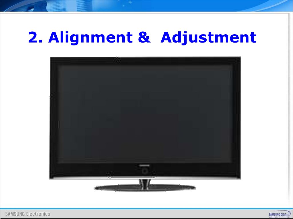
2. Alignment & Adjustment
3. Block Diagram
4. Wiring Diagram
5. Operation Instruction
& Installation
6. Trouble Shooting
3.
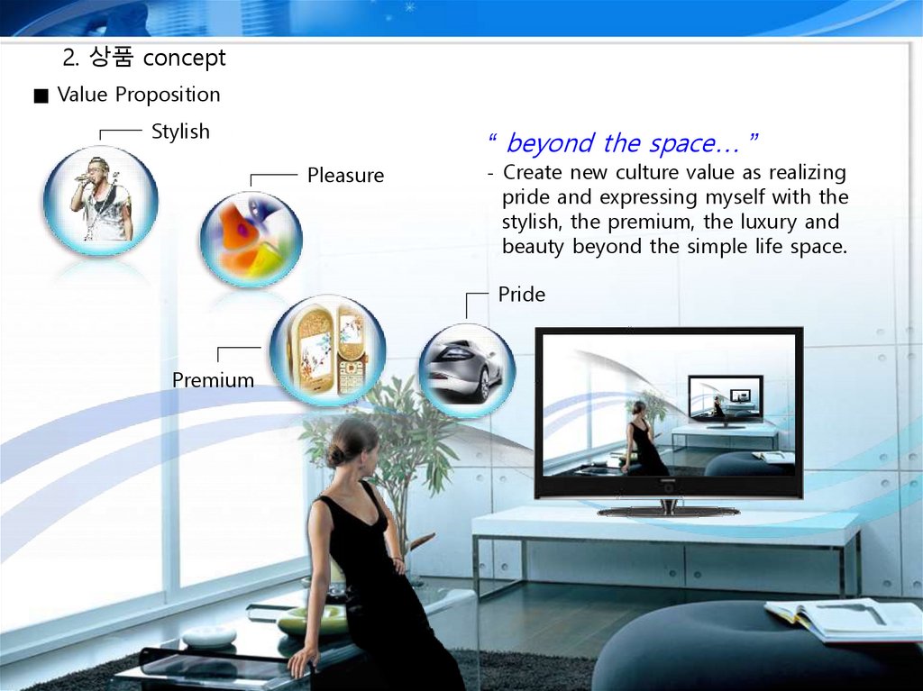
2. 상품 concept■ Value Proposition
Stylish
“ beyond the space… ”
Pleasure
- Create new culture value as realizing
pride and expressing myself with the
stylish, the premium, the luxury and
beauty beyond the simple life space.
Pride
Premium
4.
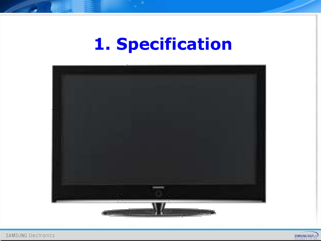
1. Specification5.
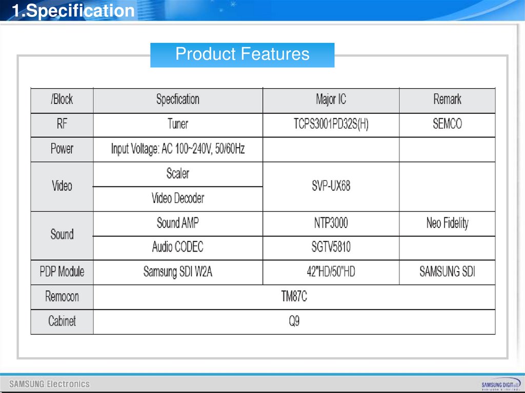
1.SpecificationProduct Features
6.
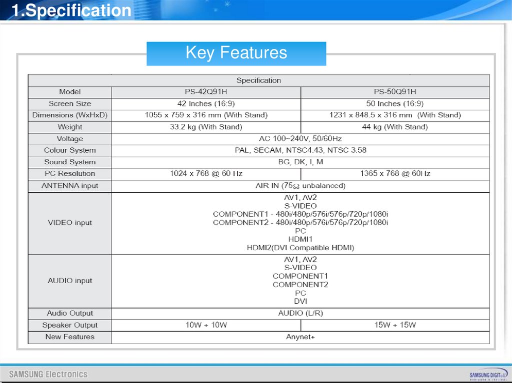
1.SpecificationKey Features
7.
2. Alignment & Adjustment8.
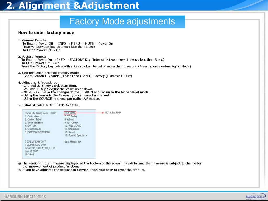
2. Alignment &AdjustmentFactory Mode adjustments
How to enter factory mode
1. General Remote
To Enter : Power Off → INFO → MENU → MUTE → Power On
(Interval between key strokes : less than 3 sec)
To Exit : Power Off → On
2. Factory Remote
To Enter : Power On → INFO → FACTORY Key (Interval between key strokes : less than 3 sec)
To Exit : Power Off → On
Press the Factory key twice with a key stroke interval of more than 1 second (Pressing once enters Aging Mode)
3. Settings when entering Factory mode
- Sharp Screen (Dynamic), Color Tone (Cool1), Factory (Dynamic CE Off)
4. Adjustment Procedures
- Channel ▲ ▼ Key : Select an item.
- Volume ◀▶ Key : Adjust the value up or down.
- MENU Key : Save the changes to the EEPROM and return to the higher-level mode.
- Using the Numeric (0~9) keys, you can select a channel.
- Using the SOURCE key, you can switch AV modes.
5. Initial SERVICE MODE DISPLAY State
※ The version of the firmware displayed at the bottom of the screen may differ and the firmware is subject to change for
the improvement of product functions.
※ If you have adjusted the settings in Service Mode, you have to reset the product.
9.
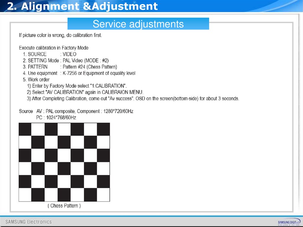
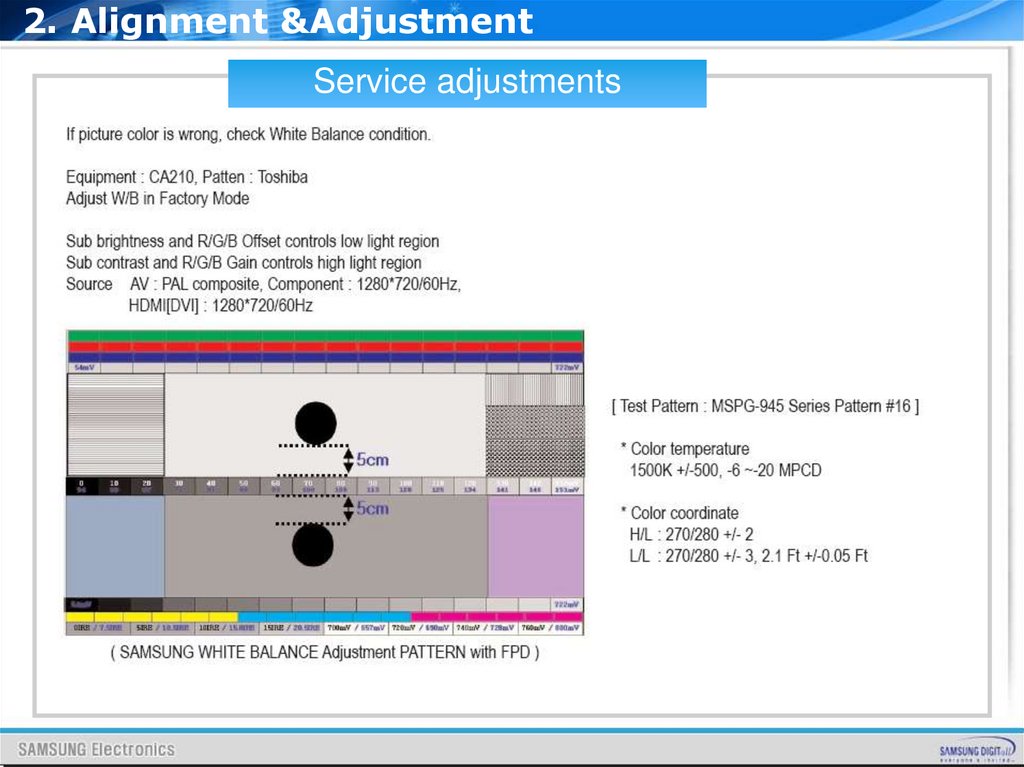
2. Alignment &AdjustmentService adjustments
10.
2. Alignment &AdjustmentService adjustments
11.
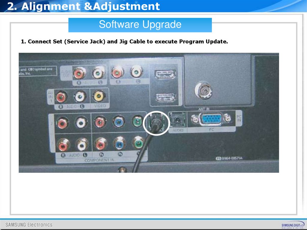
2. Alignment &AdjustmentSoftware Upgrade
1. Connect Set (Service Jack) and Jig Cable to execute Program Update.
12.
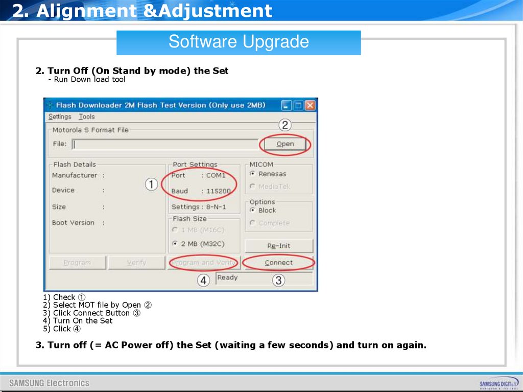
2. Alignment &AdjustmentSoftware Upgrade
2. Turn Off (On Stand by mode) the Set
- Run Down load tool
1) Check ①
2) Select MOT file by Open ②
3) Click Connect Button ③
4) Turn On the Set
5) Click ④
3. Turn off (= AC Power off) the Set (waiting a few seconds) and turn on again.
13.
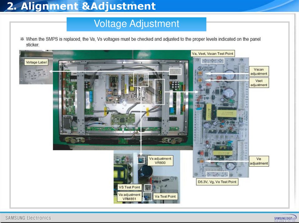
2. Alignment &AdjustmentVoltage Adjustment
14.
3. Block Diagram15.
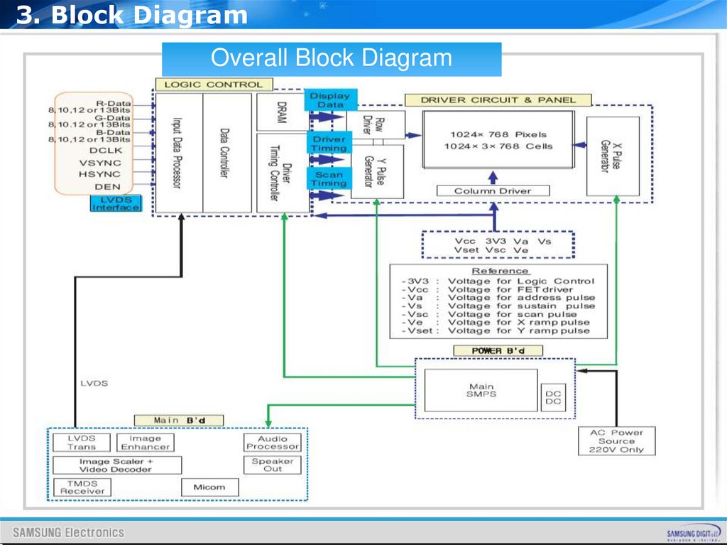
3. Block DiagramOverall Block Diagram
16.
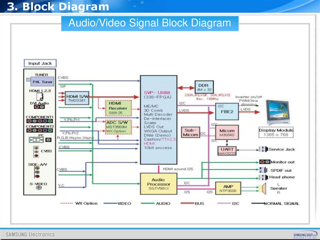
3. Block DiagramAudio/Video Signal Block Diagram
17.
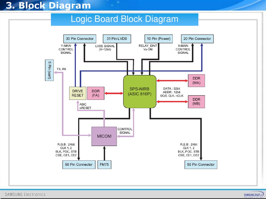
3. Block DiagramLogic Board Block Diagram
18.
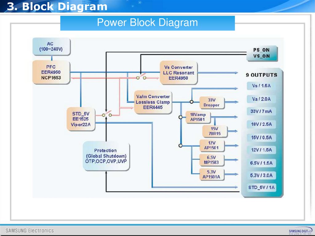
3. Block DiagramPower Block Diagram
19.
4. Wiring Diagram20.
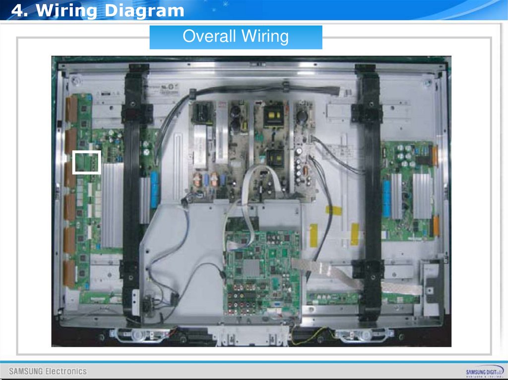
4. Wiring DiagramOverall Wiring
21.
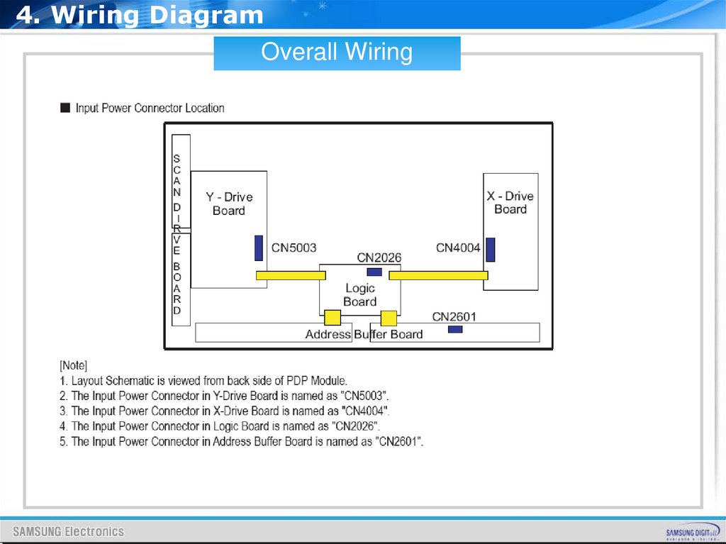
4. Wiring DiagramOverall Wiring
22.
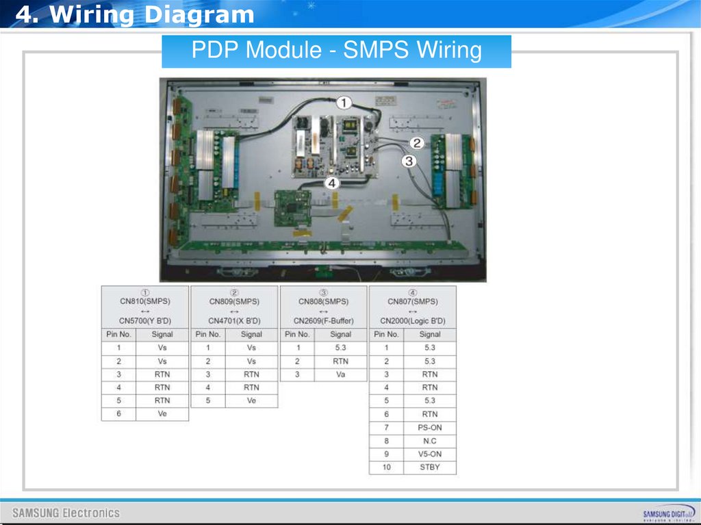
4. Wiring DiagramPDP Module - SMPS Wiring
23.
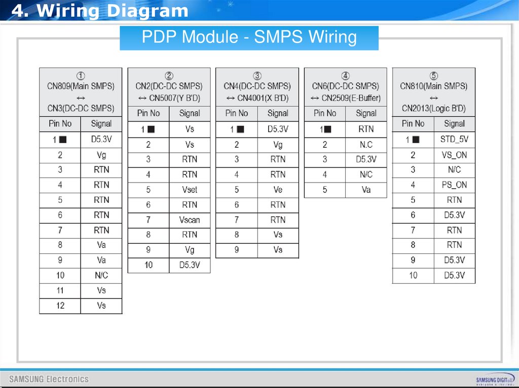
4. Wiring DiagramPDP Module - SMPS Wiring
24.
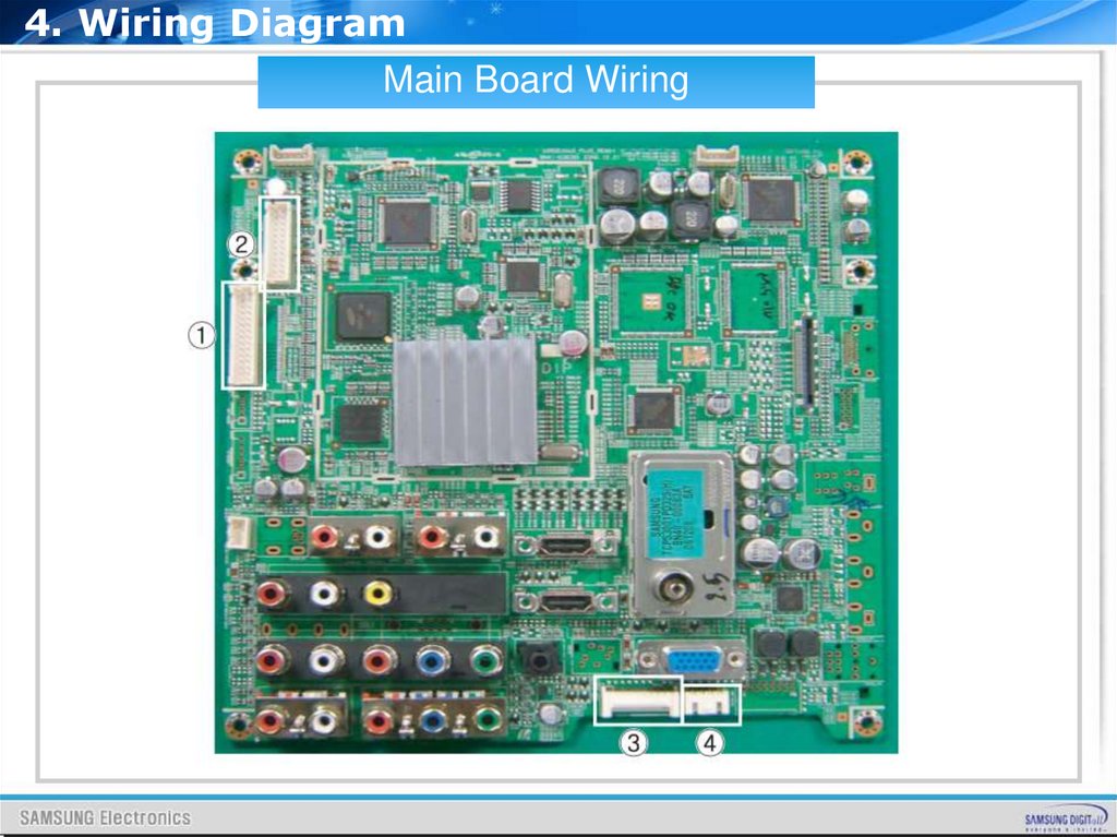
4. Wiring DiagramMain Board Wiring
25.
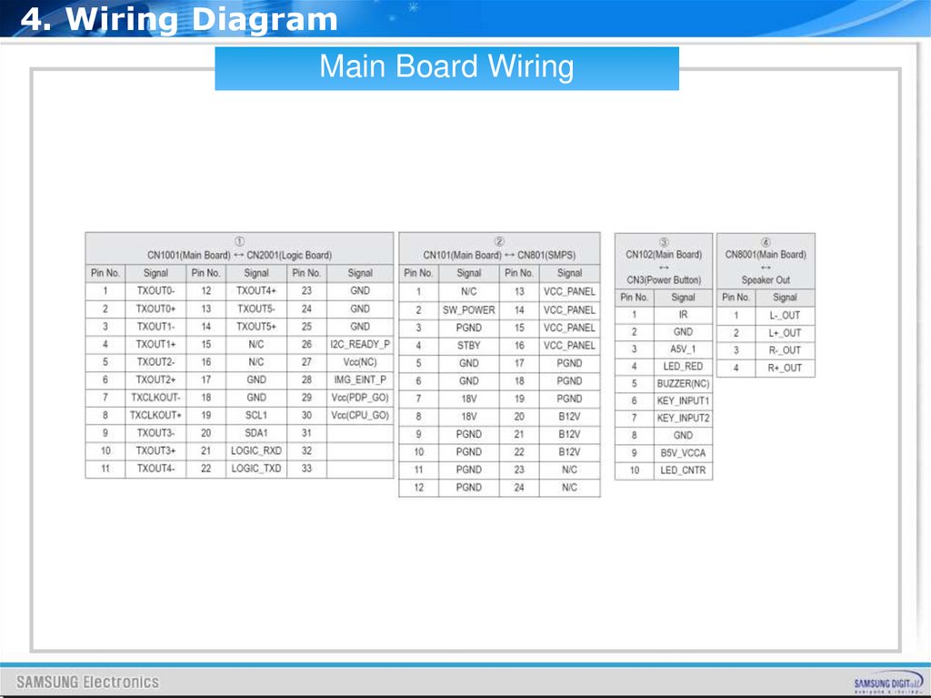
4. Wiring DiagramMain Board Wiring
26.
5. Operation Instruction& Installation
27.
5. Operation Instruction & InstallationRear Panel
28.
5. Operation Instruction & InstallationRear Panel
29.
6. Trouble shooting30.
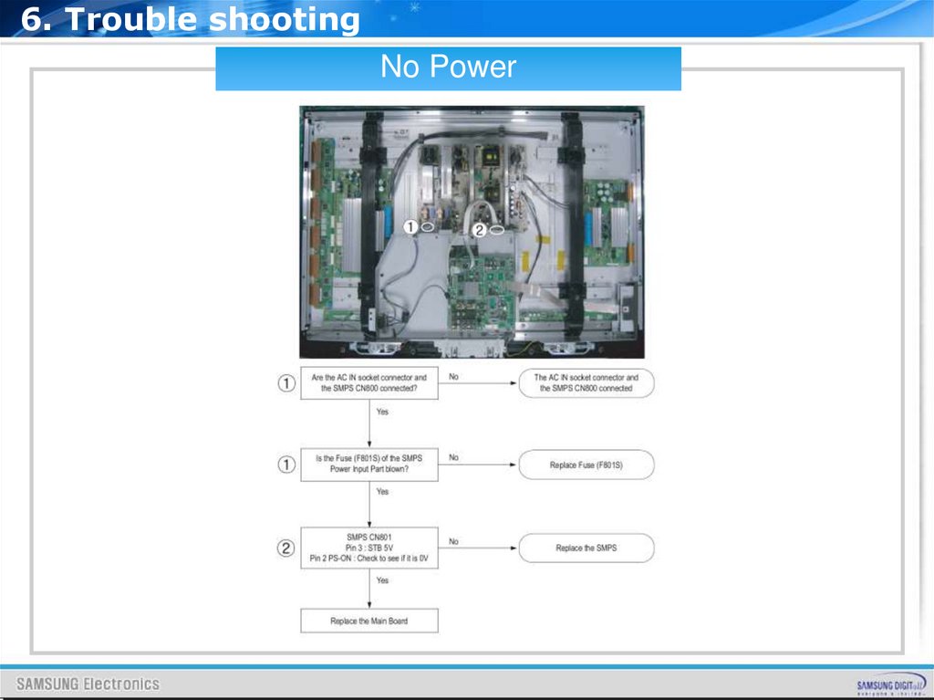
6. Trouble shootingNo Power
31.
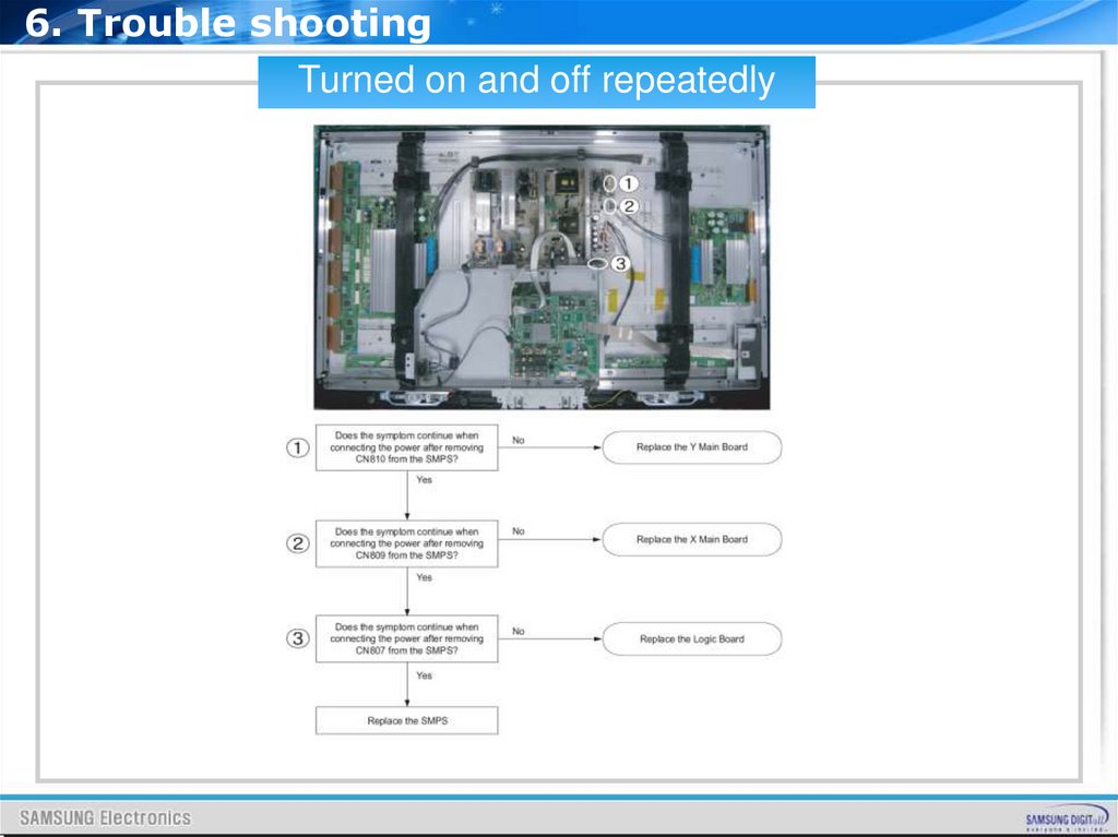
6. Trouble shootingTurned on and off repeatedly
32.
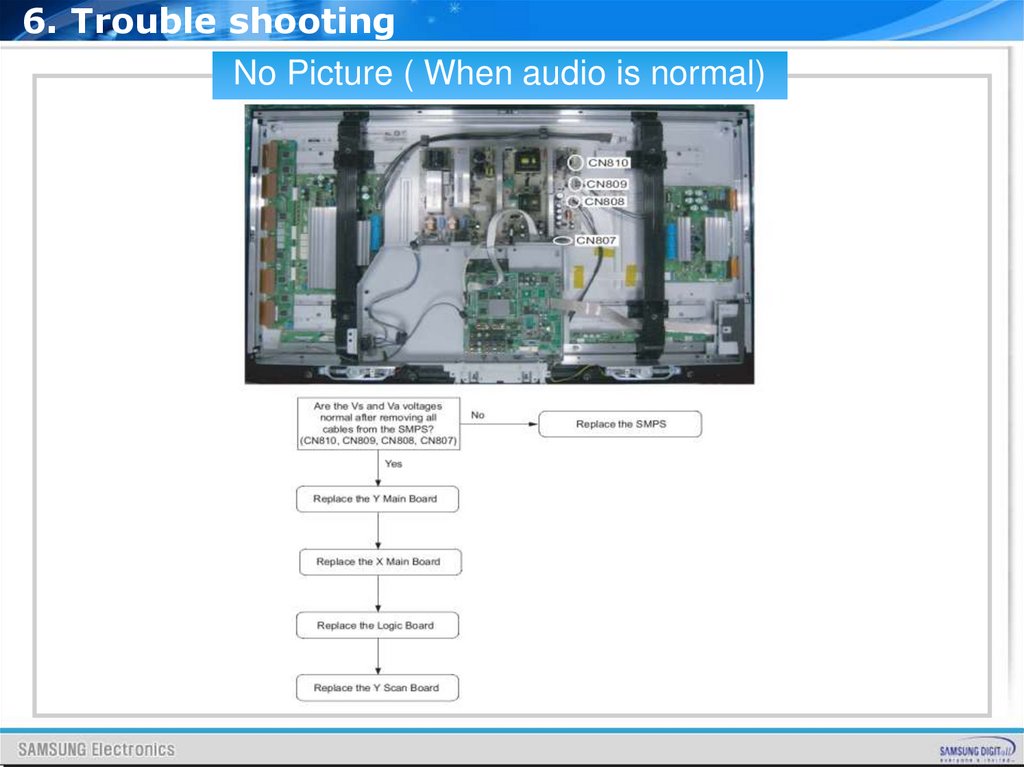
6. Trouble shootingNo Picture ( When audio is normal)
33.
6. Trouble shootingNo Sound
34.
ATTACHMENT35.
CONTENTSI.
What is PDP ?
II.
PDP Filter
III.
What is a HDMI?
IV.
What is a TrusurroundXT
V.
SVC Code List
36.
What isPDP ?
37.
Agenda1. Introduction to PDP
2. Panel Structure & Manufacturing
3. PDP Drive
4. Characteristic of Board
38.
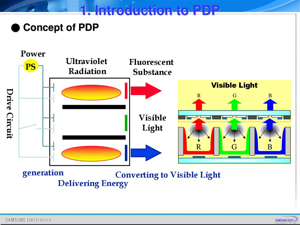
1. Introduction to PDP● Concept of PDP
Power
PS
Ultraviolet
Radiation
Fluorescent
Substance
Drive Circuit
Visible Light
R
G
B
R
G
B
Visible
Light
generation
Converting to Visible Light
Delivering Energy
39.
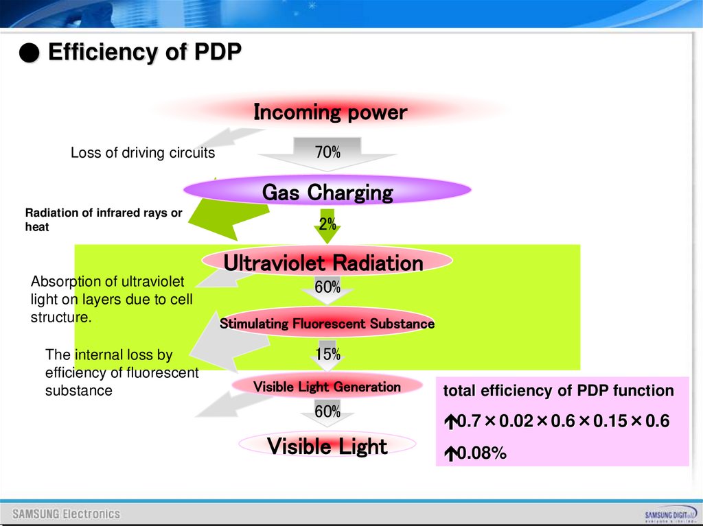
● Efficiency of PDPIncoming power
Loss of driving circuits
70%
Gas Charging
Radiation of infrared rays or
heat
2%
Ultraviolet Radiation
Absorption of ultraviolet
light on layers due to cell
structure.
The internal loss by
efficiency of fluorescent
substance
60%
Stimulating Fluorescent Substance
15%
Visible Light Generation
60%
Visible Light
total efficiency of PDP function
0.7×0.02×0.6×0.15×0.6
0.08%
40.
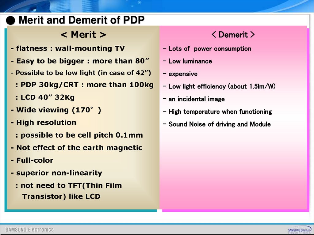
● Merit and Demerit of PDP< Merit >
< Demerit >
- flatness : wall-mounting TV
- Lots of power consumption
- Easy to be bigger : more than 80”
- Low luminance
- Possible to be low light (in case of 42”)
- expensive
: PDP 30kg/CRT : more than 100kg
- Low light efficiency (about 1.5lm/W)
: LCD 40” 32Kg
- an incidental image
- Wide viewing (170°)
- High temperature when functioning
- High resolution
- Sound Noise of driving and Module
: possible to be cell pitch 0.1mm
- Not effect of the earth magnetic
- Full-color
- superior non-linearity
: not need to TFT(Thin Film
Transistor) like LCD
41.
Panel Structure &Manufacturing
42.
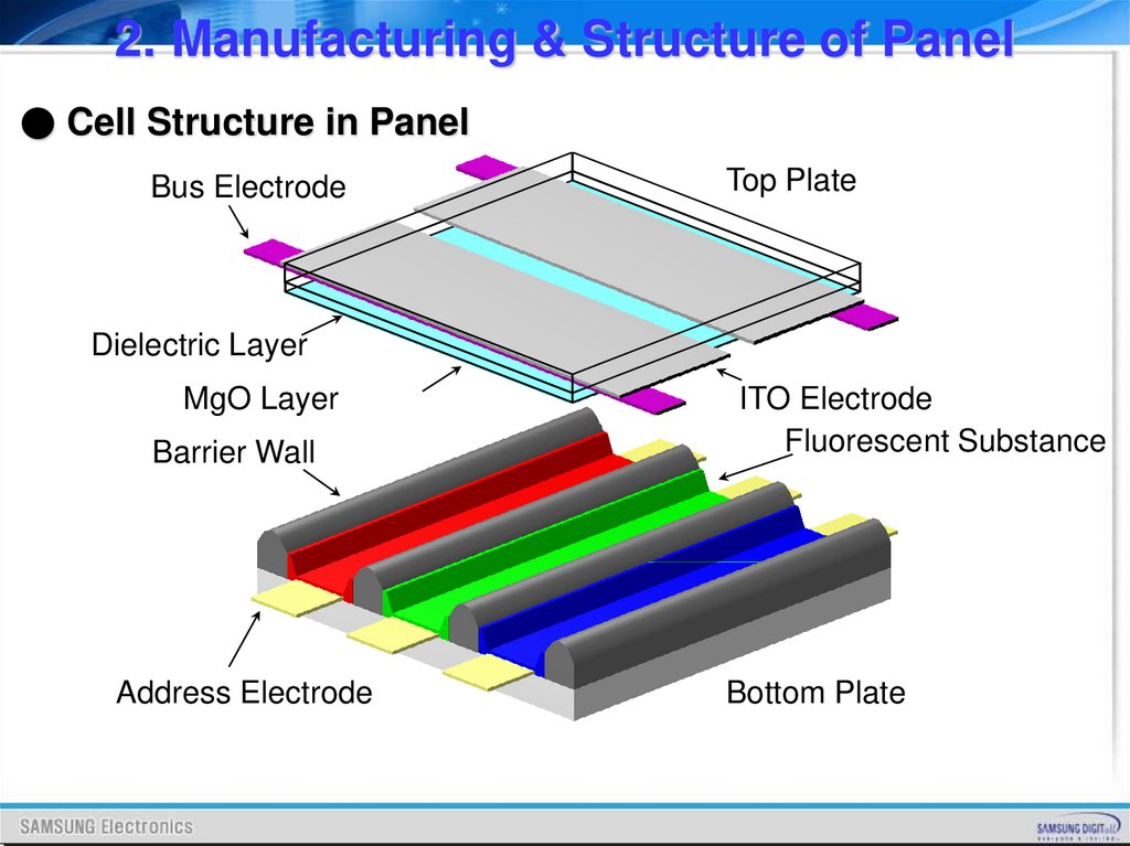
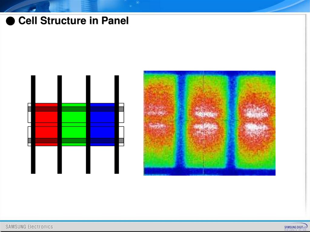
2. Manufacturing & Structure of Panel● Cell Structure in Panel
Bus Electrode
Top Plate
Dielectric Layer
MgO Layer
Barrier Wall
Address Electrode
ITO Electrode
Fluorescent Substance
Bottom Plate
43.
● Cell Structure in Panel44.
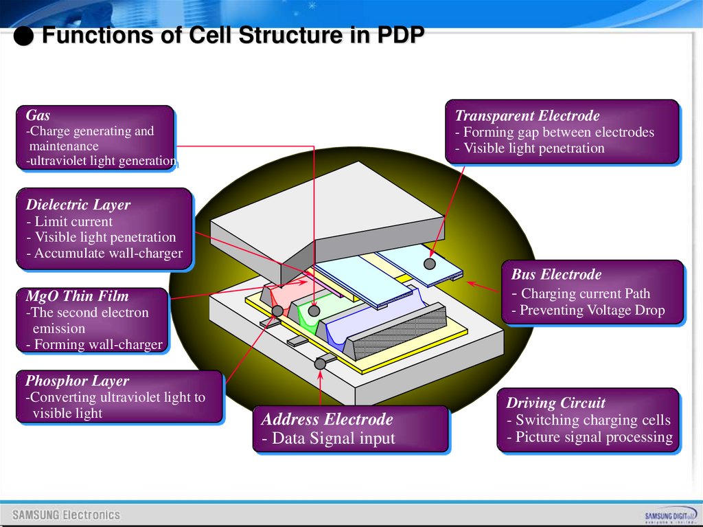
● Functions of Cell Structure in PDPGas
Transparent Electrode
-Charge generating and
maintenance
-ultraviolet light generation
- Forming gap between electrodes
- Visible light penetration
Dielectric Layer
- Limit current
- Visible light penetration
- Accumulate wall-charger
Bus Electrode
MgO Thin Film
- Charging current Path
-The second electron
emission
- Forming wall-charger
- Preventing Voltage Drop
Phosphor Layer
-Converting ultraviolet light to
visible light
Address Electrode
- Data Signal input
Driving Circuit
- Switching charging cells
- Picture signal processing
45.
PDP Drive46.
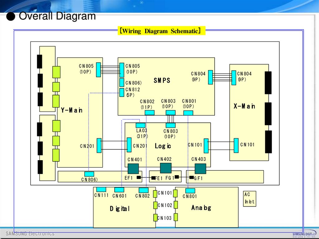
● Overall Diagram[Wiring Diagram Schematic]
C N 805
(10 P )
C N 805
(10 P )
SM PS
C N 806)
C N 812
(5P )
C N 802 C N 803
(10 P )
(11 P )
Y - M ain
LA 03
(31 P )
C N 201
C N 201
C N 806)
C N 804
(9P )
C N 801
(10 P )
Log ic
C N 101
C N 402
C N 403
E F1
FE 1 FG 1
G F1
D igital
C N 802
X - M ain
C N 803
(10 P )
C N 401
C N 111 C N 601
C N 804
(9P )
C N 101
C N 102
C N 103
C N 801
C N 101
AC
Inlet
A nalog
47.
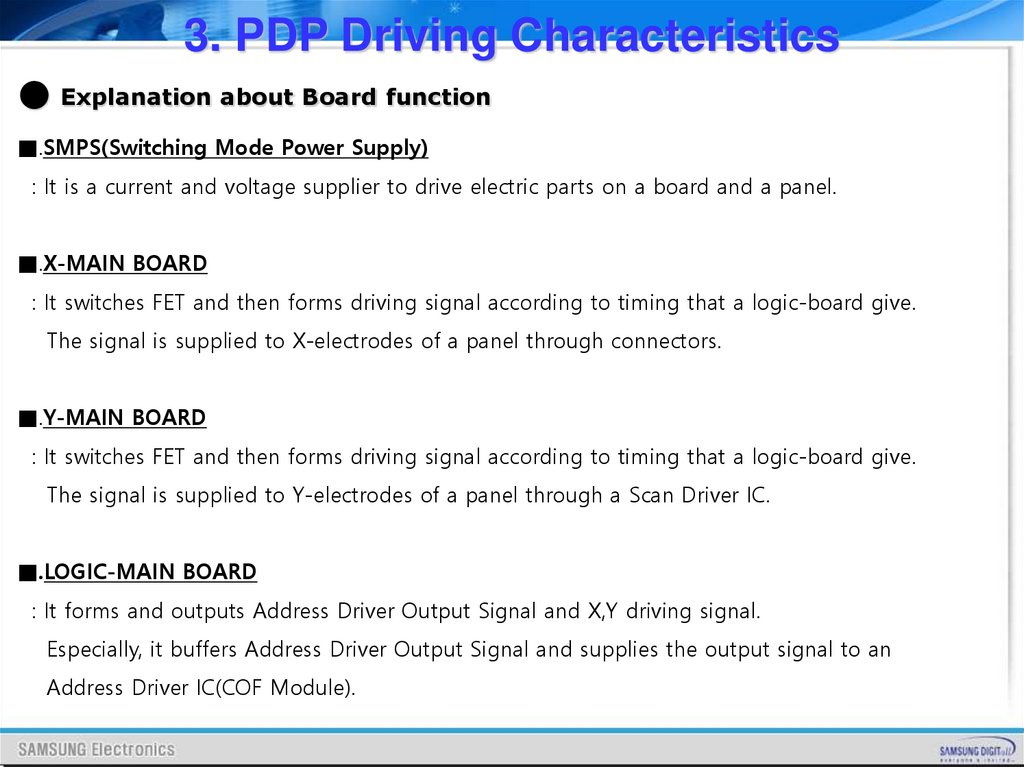
3. PDP Driving Characteristics● Explanation about Board function
■.SMPS(Switching Mode Power Supply)
: It is a current and voltage supplier to drive electric parts on a board and a panel.
■.X-MAIN BOARD
: It switches FET and then forms driving signal according to timing that a logic-board give.
The signal is supplied to X-electrodes of a panel through connectors.
■.Y-MAIN BOARD
: It switches FET and then forms driving signal according to timing that a logic-board give.
The signal is supplied to Y-electrodes of a panel through a Scan Driver IC.
■.LOGIC-MAIN BOARD
: It forms and outputs Address Driver Output Signal and X,Y driving signal.
Especially, it buffers Address Driver Output Signal and supplies the output signal to an
Address Driver IC(COF Module).
48.
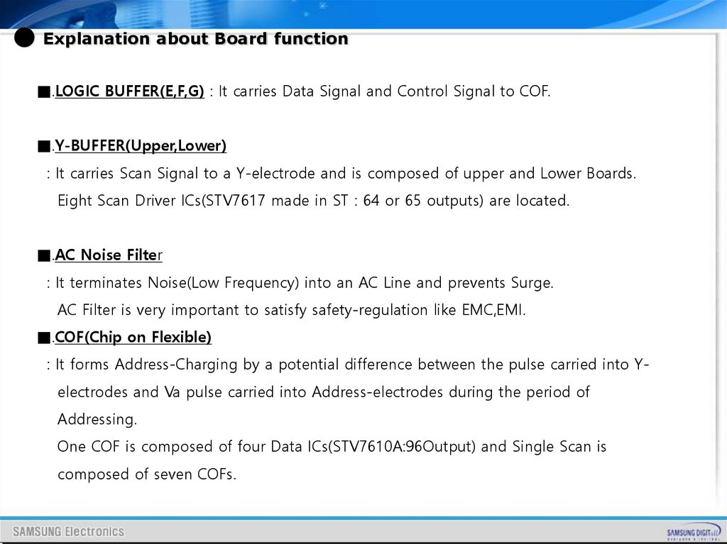
● Explanation about Board function■.LOGIC BUFFER(E,F,G) : It carries Data Signal and Control Signal to COF.
■.Y-BUFFER(Upper,Lower)
: It carries Scan Signal to a Y-electrode and is composed of upper and Lower Boards.
Eight Scan Driver ICs(STV7617 made in ST : 64 or 65 outputs) are located.
■.AC Noise Filter
: It terminates Noise(Low Frequency) into an AC Line and prevents Surge.
AC Filter is very important to satisfy safety-regulation like EMC,EMI.
■.COF(Chip on Flexible)
: It forms Address-Charging by a potential difference between the pulse carried into Yelectrodes and Va pulse carried into Address-electrodes during the period of
Addressing.
One COF is composed of four Data ICs(STV7610A:96Output) and Single Scan is
composed of seven COFs.
49.
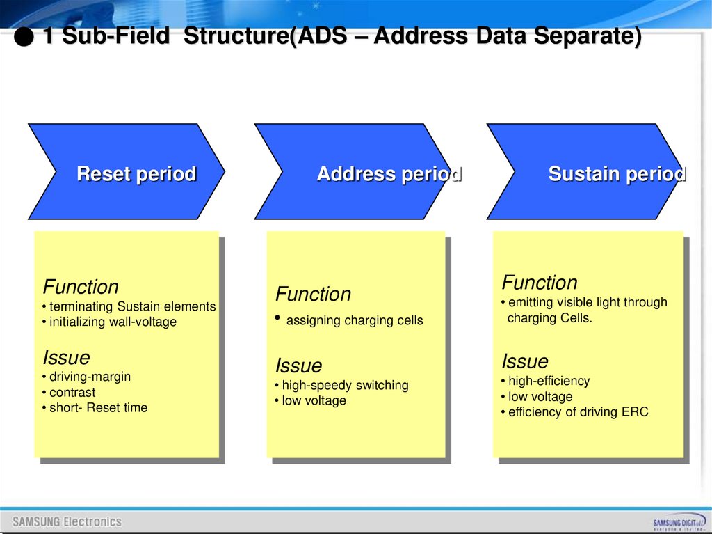
● 1 Sub-Field Structure(ADS – Address Data Separate)Reset period
Function
• terminating Sustain elements
• initializing wall-voltage
Issue
• driving-margin
• contrast
• short- Reset time
Address period
Function
• assigning charging cells
Issue
• high-speedy switching
• low voltage
Sustain period
Function
• emitting visible light through
charging Cells.
Issue
• high-efficiency
• low voltage
• efficiency of driving ERC
50.
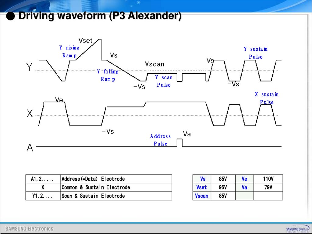
● Driving waveform (P3 Alexander)Y rising
Y sustain
R am p
P ulse
Y falling
R am p
Y scan
P ulse
X sustain
P ulse
A ddress
P ulse
A1,2.....
Address(=Data) Electrode
Vs
85V
Ve
110V
X
Common & Sustain Electrode
Vset
95V
Va
79V
Y1,2....
Scan & Sustain Electrode
Vscan
85V
51.
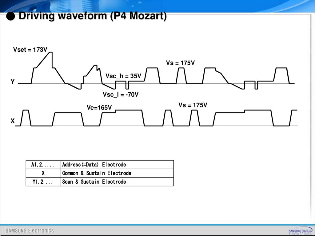
● Driving waveform (P4 Mozart)Vset = 173V
Vs = 175V
Vsc_h = 35V
Y
Vsc_l = -70V
Ve=165V
X
A1,2.....
Address(=Data) Electrode
X
Common & Sustain Electrode
Y1,2....
Scan & Sustain Electrode
Vs = 175V
52.
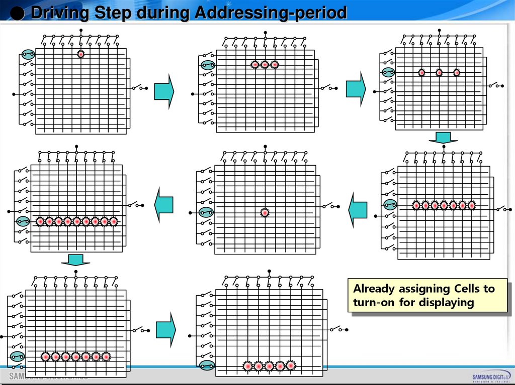
● Driving Step during Addressing-periodAlready assigning Cells to
turn-on for displaying
53.
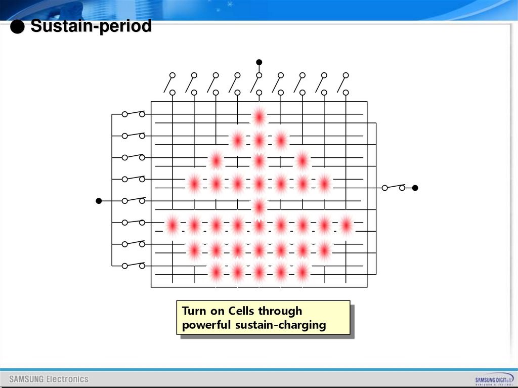
● Sustain-periodTurn on Cells through
powerful sustain-charging
54.
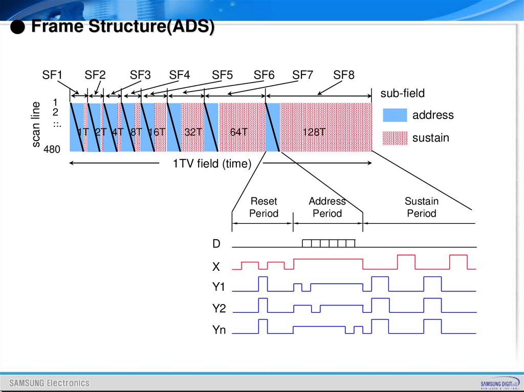
● Frame Structure(ADS)scan line
SF1
1
2
..
...
SF2
SF3
SF4
SF5
SF6
SF7
SF8
sub-field
address
1T 2T 4T 8T 16T
32T
64T
128T
sustain
480
1TV field (time)
Reset
Period
D
X
Y1
Y2
Yn
Address
Period
Sustain
Period
55.
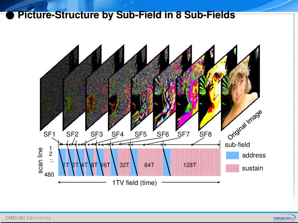
● Picture-Structure by Sub-Field in 8 Sub-Fieldsscan line
SF1
1
2
..
...
SF2
SF3
SF4
SF5
SF6
SF7
SF8
sub-field
address
1T 2T 4T 8T 16T
32T
64T
480
1TV field (time)
128T
sustain
56.
Characteristic of Board57.
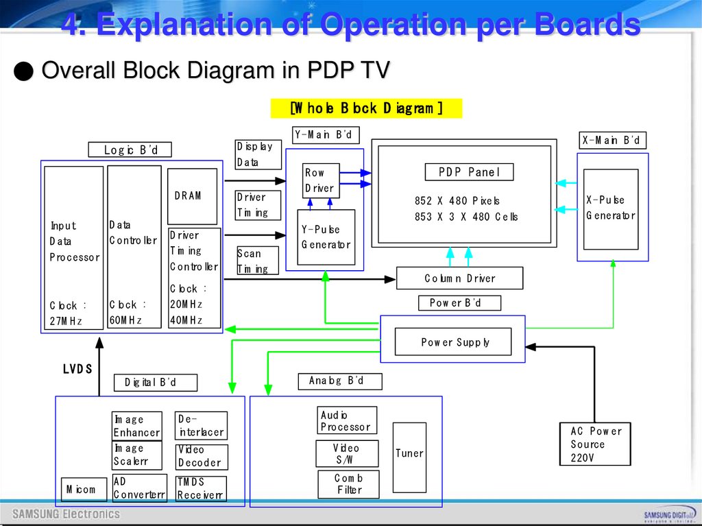
4. Explanation of Operation per Boards● Overall Block Diagram in PDP TV
[W hole B lock D iagram ]
Y - M ain B 'd
Lo g ic B 'd
D ata
D RAM
Inp ut
D ata
D ata
C o ntro ller
P ro cesso r
X - M ain B 'd
D isp lay
D river
Tim ing
D river
Tim ing
C o ntro ller
C lo ck :
C lo ck :
C lo ck :
20M H z
27M H z
60M H z
40M H z
S can
Tim ing
P D P P anel
Row
D river
852 X 4 80 P ixels
853 X 3 X 480 C ells
X - P ulse
G enerato r
Y - P ulse
G enerato r
C o lum n D river
P o w er B 'd
P o w er S up p ly
LV D S
A nalo g B 'd
D ig ital B 'd
M ico m
Im ag e
E nhancer
D einterlacer
A ud io
P ro cesso r
Im ag e
S calerr
Vid eo
D eco d er
Vid eo
S /W
AD
C o nverterr
TM D S
R eceiverr
C om b
Filter
Tuner
A C P o w er
S o urce
220V
58.
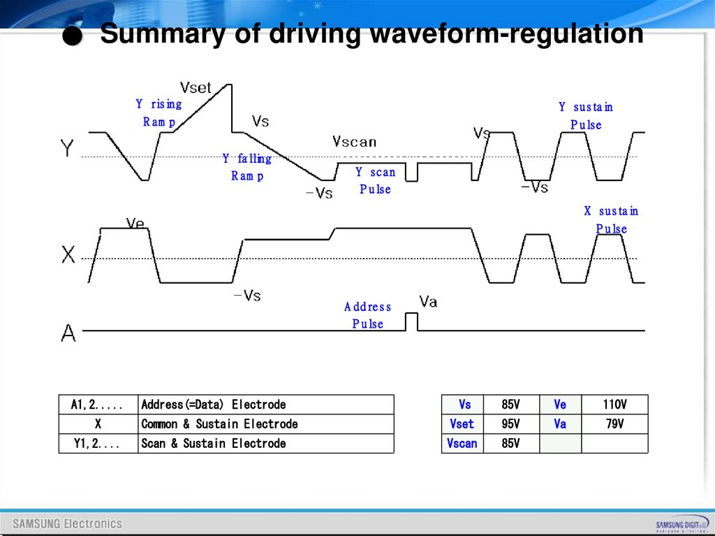
● Summary of driving waveform-regulationY rising
Y sustain
R am p
P ulse
Y falling
R am p
Y scan
P ulse
X sustain
P ulse
A ddress
P ulse
A1,2.....
Address(=Data) Electrode
Vs
85V
Ve
110V
X
Common & Sustain Electrode
Vset
95V
Va
79V
Y1,2....
Scan & Sustain Electrode
Vscan
85V
59.
What isPDP Filter ?
60.
ContentPDP Filter Function
PDP Filter Structure
PDP Filter Performance
PDP Filter Manufacturing Process
61.
PDP Filter Function62.
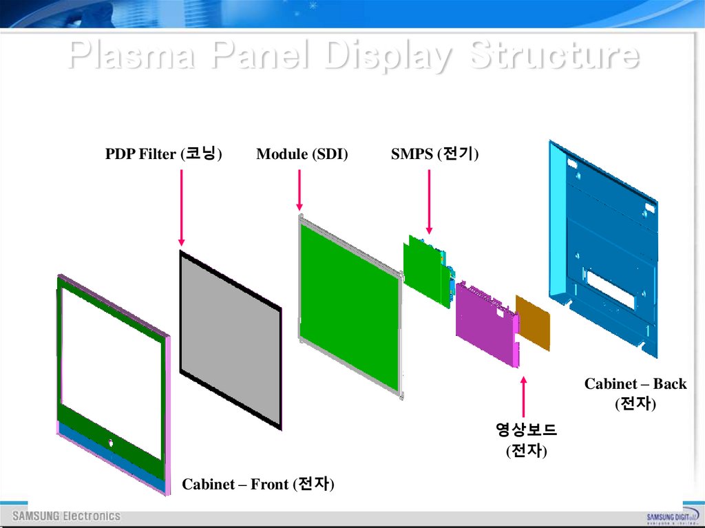
Plasma Panel Display StructurePDP Filter (코닝)
Module (SDI)
SMPS (전기)
Cabinet – Back
(전자)
영상보드
(전자)
Cabinet – Front (전자)
63.
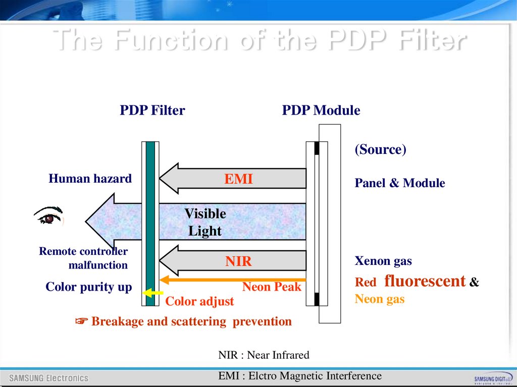
The Function of the PDP FilterPDP Filter
PDP Module
(Source)
Human hazard
EMI
Panel & Module
Visible
Light
Remote controller
malfunction
NIR
Color purity up
Neon Peak
Color adjust
Xenon gas
Red fluorescent &
Neon gas
☞ Breakage and scattering prevention
NIR : Near Infrared
EMI : Elctro Magnetic Interference
64.
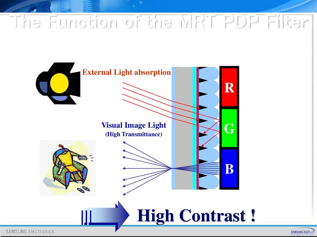
The Function of the MRT PDP FilterExternal Light absorption
R
Visual Image Light
(High Transmittance)
G
B
High Contrast !
65.
PDP Filter Structure66.
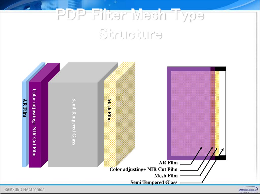
PDP Filter Mesh TypeStructure
Mesh Film
Semi Tempered Glass
Color adjusting+ NIR Cut Film
AR Film
AR Film
Color adjusting+ NIR Cut Film
Mesh Film
Semi Tempered Glass
67.
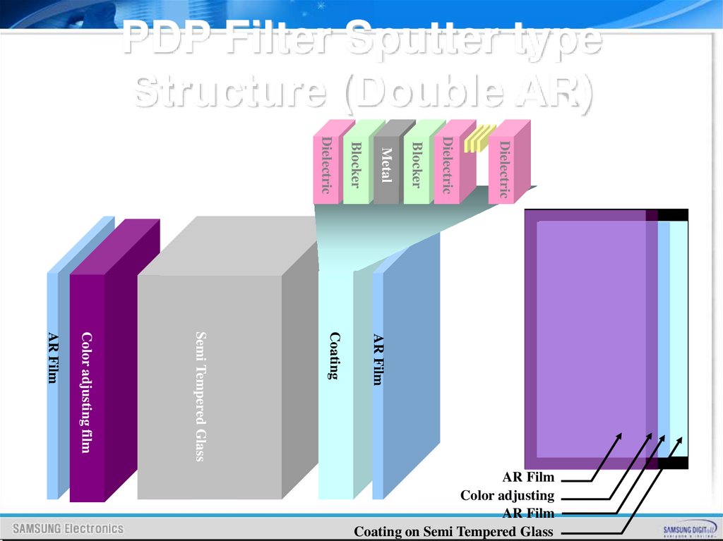
PDP Filter Sputter typeStructure (Double AR)
Dielectric
Dielectric
Blocker
Metal
Blocker
Dielectric
AR Film
Coating
Semi Tempered Glass
Color adjusting film
AR Film
AR Film
Color adjusting
AR Film
Coating on Semi Tempered Glass
68.
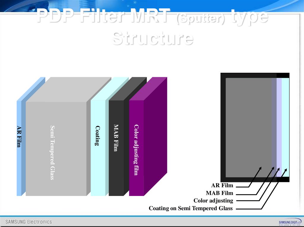
PDP Filter MRT (Sputter) typeStructure
Color adjusting film
MAB Film
Coating
Semi Tempered Glass
AR Film
AR Film
MAB Film
Color adjusting
Coating on Semi Tempered Glass
69.
PDP Filter Performance70.
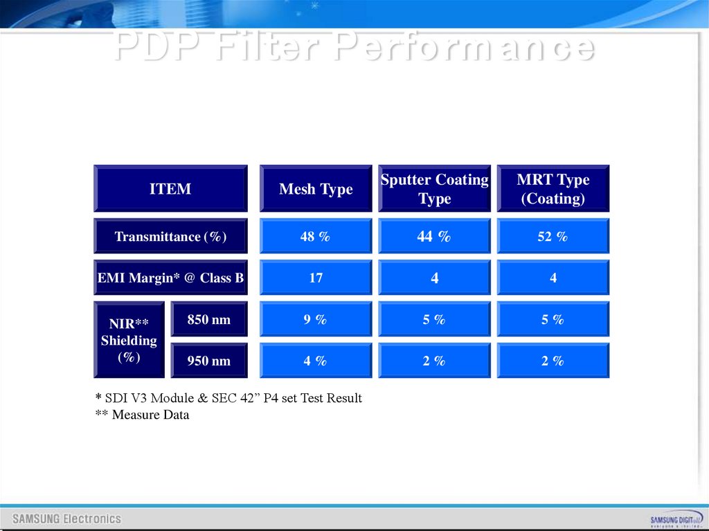
PDP Filter Perfo rm an ceITEM
Mesh Type
Sputter Coating
Type
MRT Type
(Coating)
Transmittance (%)
48 %
44 %
52 %
EMI Margin* @ Class B
17
4
4
850 nm
9%
5%
5%
950 nm
4%
2%
2%
NIR**
Shielding
(%)
* SDI V3 Module & SEC 42” P4 set Test Result
** Measure Data
71.
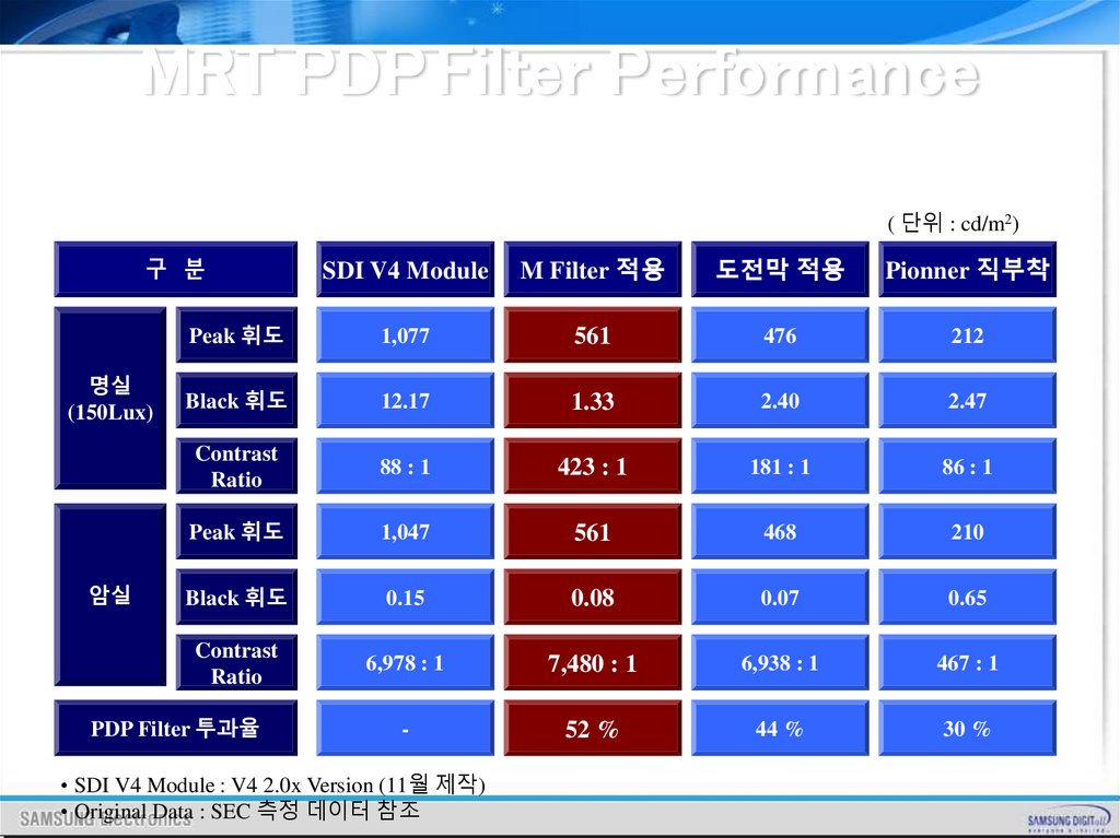
MRT PDP Filter Performance( 단위 : cd/m2)
SDI V4 Module
M Filter 적용
도전막 적용
Pionner 직부착
Peak 휘도
1,077
561
476
212
Black 휘도
12.17
1.33
2.40
2.47
Contrast
Ratio
88 : 1
423 : 1
181 : 1
86 : 1
Peak 휘도
1,047
561
468
210
Black 휘도
0.15
0.08
0.07
0.65
Contrast
Ratio
6,978 : 1
7,480 : 1
6,938 : 1
467 : 1
-
52 %
44 %
30 %
구 분
명실
(150Lux)
암실
PDP Filter 투과율
• SDI V4 Module : V4 2.0x Version (11월 제작)
• Original Data : SEC 측정 데이터 참조
72.
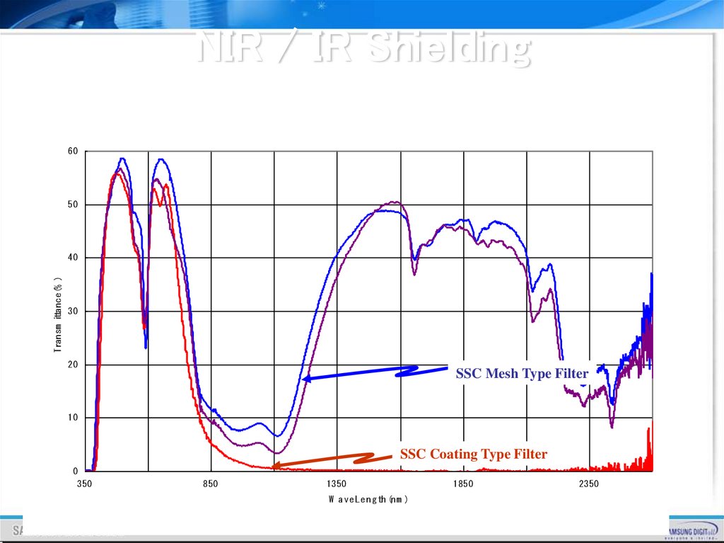
NIR / IR Shielding60
50
Transm ittance(% )
40
30
20
SSC Mesh Type Filter
10
SSC Coating Type Filter
0
350
850
1350
W a ve Le n g th (n m )
1850
2350
73.
PDP Filter Manufacturing Process74.
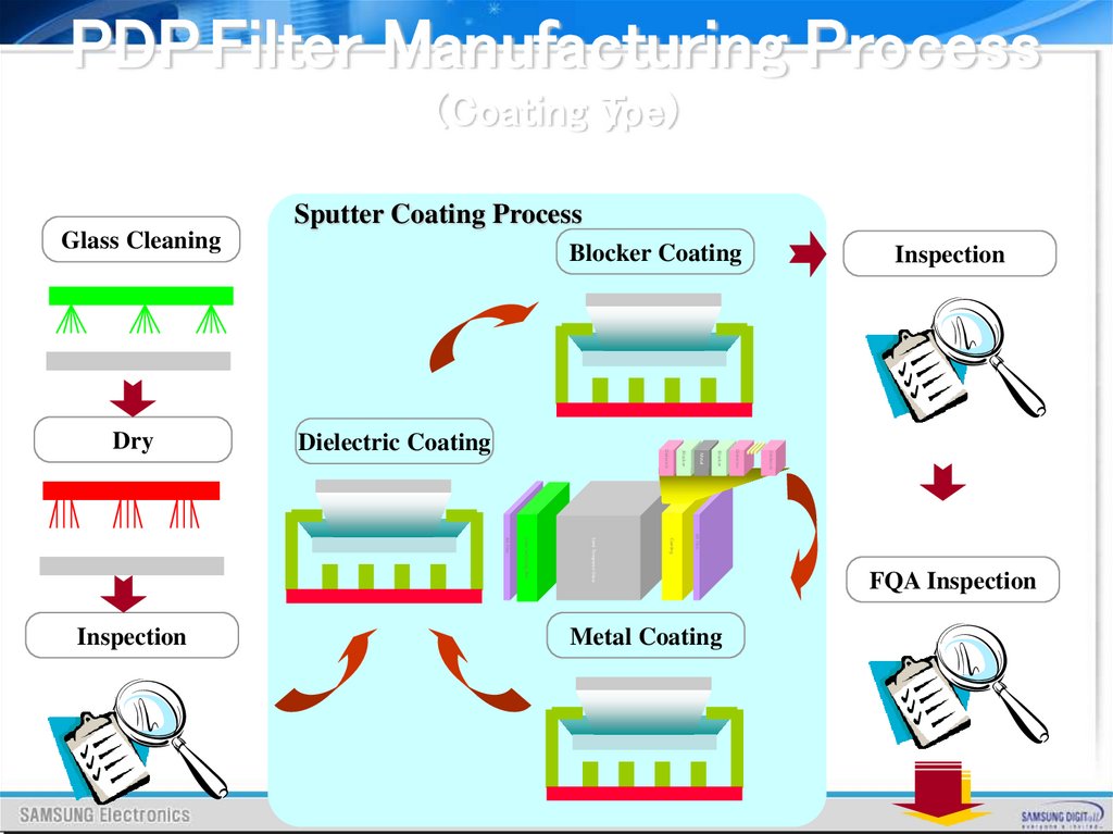
PDP Filter Manufacturing Process(Coating yTpe)
Sputter Coating Process
Glass Cleaning
Inspection
Dielectric
Blocker
Dielectric
Metal
AR Film
Coating
Semi Tempered Glass
Color adjusting film
AR Film
Inspection
Blocker
Dielectric Coating
Dielectric
Dry
Blocker Coating
Metal Coating
FQA Inspection
75.
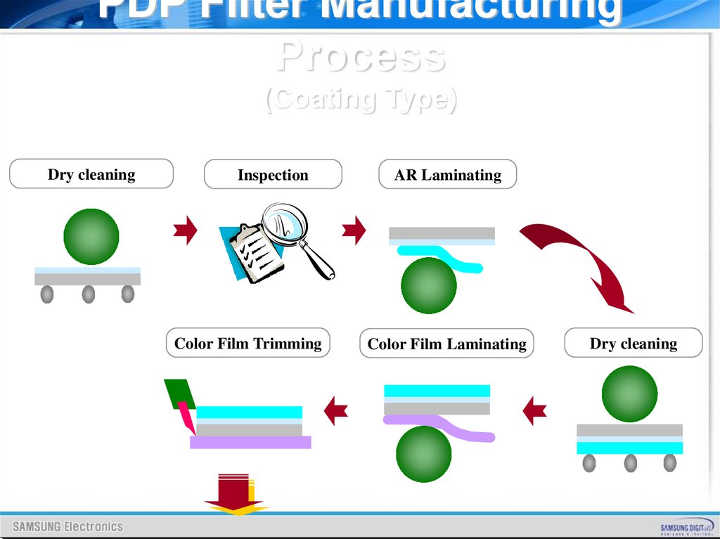
PDP Filter ManufacturingProcess
(Coating Type)
Dry cleaning
Inspection
Color Film Trimming
AR Laminating
Color Film Laminating
Dry cleaning
76.
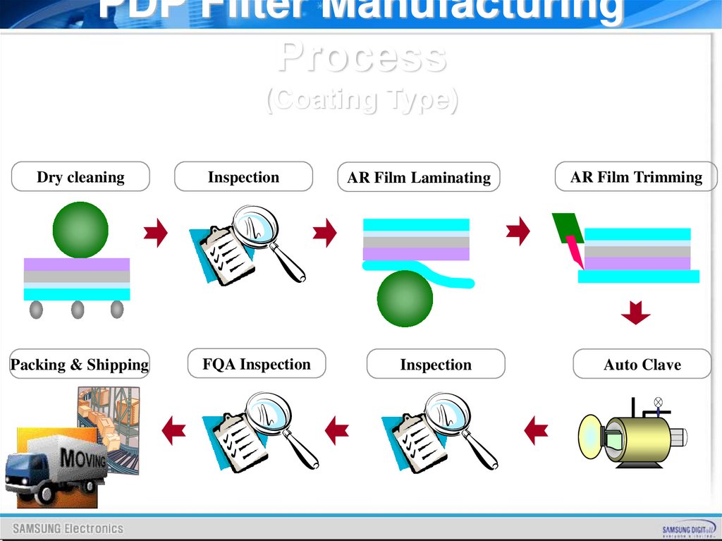
PDP Filter ManufacturingProcess
(Coating Type)
Dry cleaning
Packing & Shipping
Inspection
FQA Inspection
AR Film Laminating
Inspection
AR Film Trimming
Auto Clave
77.
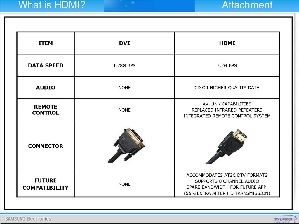
What is HDMI?Attachment
ITEM
DVI
HDMI
DATA SPEED
1.78G BPS
2.2G BPS
AUDIO
NONE
CD OR HIGHER QUALITY DATA
NONE
AV-LINK CAPABILITIES
REPLACES INFRARED REPEATERS
INTEGRATED REMOTE CONTROL SYSTEM
NONE
ACCOMMODATES ATSC DTV FORMATS
SUPPORTS 8 CHANNEL AUDIO
SPARE BANDWIDTH FOR FUTURE APP.
(55% EXTRA AFTER HD TRANSMISSION)
REMOTE
CONTROL
CONNECTOR
FUTURE
COMPATIBILITY
78.
What is HDMI?Attachment
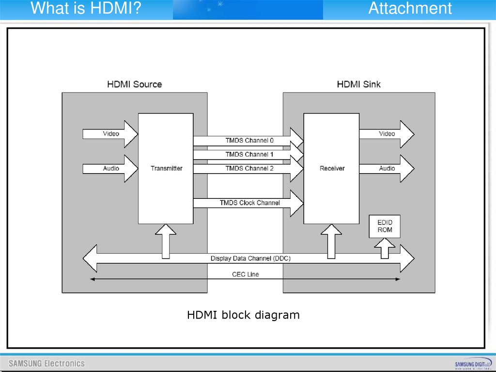
HDMI block diagram
79.
What is HDMI?Attachment
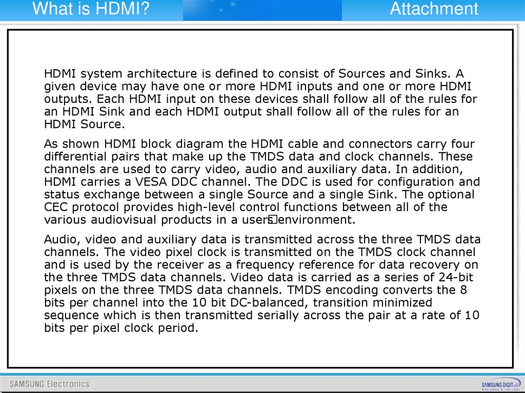
HDMI system architecture is defined to consist of Sources and Sinks. A
given device may have one or more HDMI inputs and one or more HDMI
outputs. Each HDMI input on these devices shall follow all of the rules for
an HDMI Sink and each HDMI output shall follow all of the rules for an
HDMI Source.
As shown HDMI block diagram the HDMI cable and connectors carry four
differential pairs that make up the TMDS data and clock channels. These
channels are used to carry video, audio and auxiliary data. In addition,
HDMI carries a VESA DDC channel. The DDC is used for configuration and
status exchange between a single Source and a single Sink. The optional
CEC protocol provides high-level control functions between all of the
various audiovisual products in a user
s environment.
Audio, video and auxiliary data is transmitted across the three TMDS data
channels. The video pixel clock is transmitted on the TMDS clock channel
and is used by the receiver as a frequency reference for data recovery on
the three TMDS data channels. Video data is carried as a series of 24-bit
pixels on the three TMDS data channels. TMDS encoding converts the 8
bits per channel into the 10 bit DC-balanced, transition minimized
sequence which is then transmitted serially across the pair at a rate of 10
bits per pixel clock period.
80.
What is HDMI?Attachment
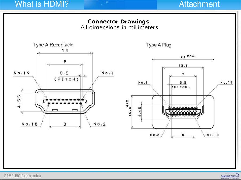
Connector Drawings
All dimensions in millimeters
81.
What is HDMI?Attachment
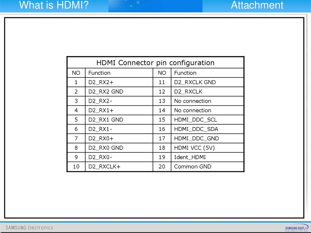
HDMI Connector pin configuration
NO
Function
NO
Function
1
D2_RX2+
11
D2_RXCLK GND
2
D2_RX2 GND
12
D2_RXCLK
3
D2_RX2-
13
No connection
4
D2_RX1+
14
No connection
5
D2_RX1 GND
15
HDMI_DDC_SCL
6
D2_RX1-
16
HDMI_DDC_SDA
7
D2_RX0+
17
HDMI_DDC_GND
8
D2_RX0 GND
18
HDMI VCC (5V)
9
D2_RX0-
19
Ident_HDMI
10
D2_RXCLK+
20
Common GND
82.
What is HDMI?Attachment
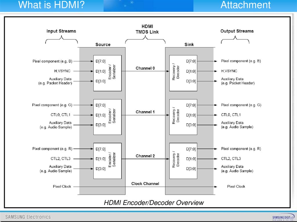
HDMI Encoder/Decoder Overview
83.
What is HDMI?Attachment
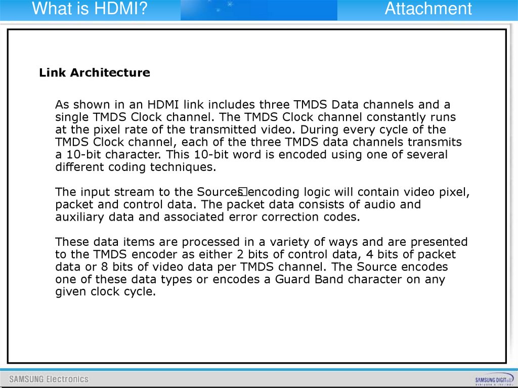
Link Architecture
As shown in an HDMI link includes three TMDS Data channels and a
single TMDS Clock channel. The TMDS Clock channel constantly runs
at the pixel rate of the transmitted video. During every cycle of the
TMDS Clock channel, each of the three TMDS data channels transmits
a 10-bit character. This 10-bit word is encoded using one of several
different coding techniques.
The input stream to the Source
s encoding logic will contain video pixel,
packet and control data. The packet data consists of audio and
auxiliary data and associated error correction codes.
These data items are processed in a variety of ways and are presented
to the TMDS encoder as either 2 bits of control data, 4 bits of packet
data or 8 bits of video data per TMDS channel. The Source encodes
one of these data types or encodes a Guard Band character on any
given clock cycle.
84.
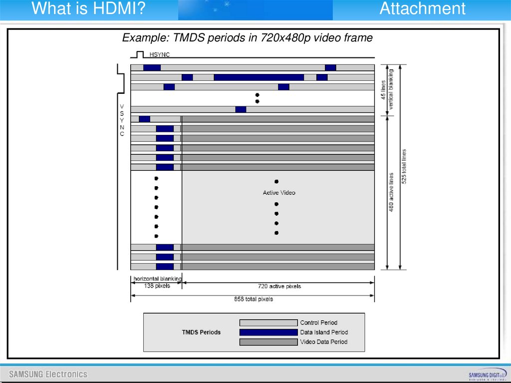
What is HDMI?Example: TMDS periods in 720x480p video frame
Attachment
85.
What is HDMI?Attachment
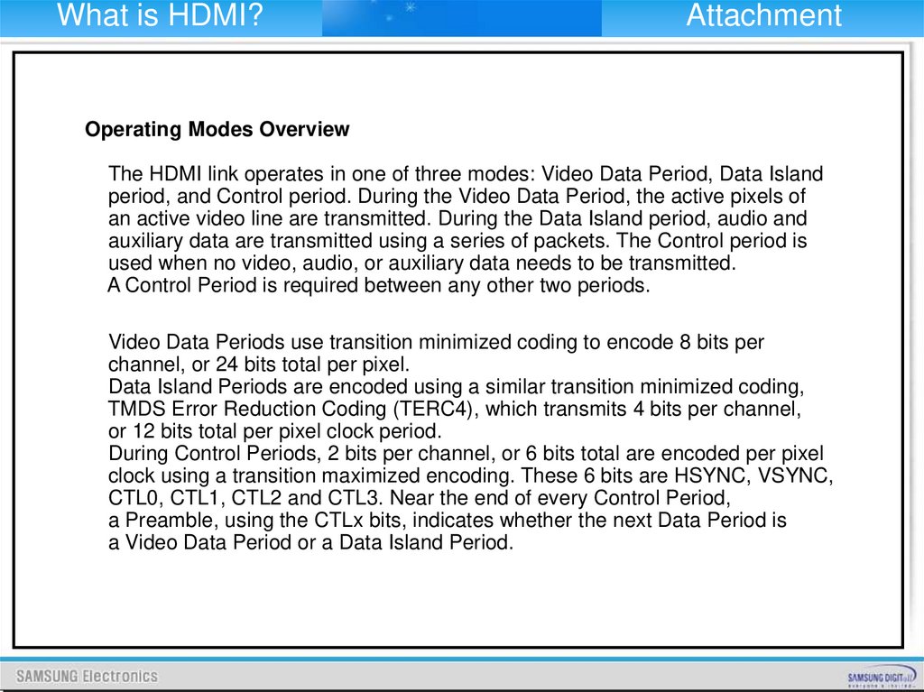
Operating Modes Overview
The HDMI link operates in one of three modes: Video Data Period, Data Island
period, and Control period. During the Video Data Period, the active pixels of
an active video line are transmitted. During the Data Island period, audio and
auxiliary data are transmitted using a series of packets. The Control period is
used when no video, audio, or auxiliary data needs to be transmitted.
A Control Period is required between any other two periods.
Video Data Periods use transition minimized coding to encode 8 bits per
channel, or 24 bits total per pixel.
Data Island Periods are encoded using a similar transition minimized coding,
TMDS Error Reduction Coding (TERC4), which transmits 4 bits per channel,
or 12 bits total per pixel clock period.
During Control Periods, 2 bits per channel, or 6 bits total are encoded per pixel
clock using a transition maximized encoding. These 6 bits are HSYNC, VSYNC,
CTL0, CTL1, CTL2 and CTL3. Near the end of every Control Period,
a Preamble, using the CTLx bits, indicates whether the next Data Period is
a Video Data Period or a Data Island Period.
86.
What is HDMI?Attachment
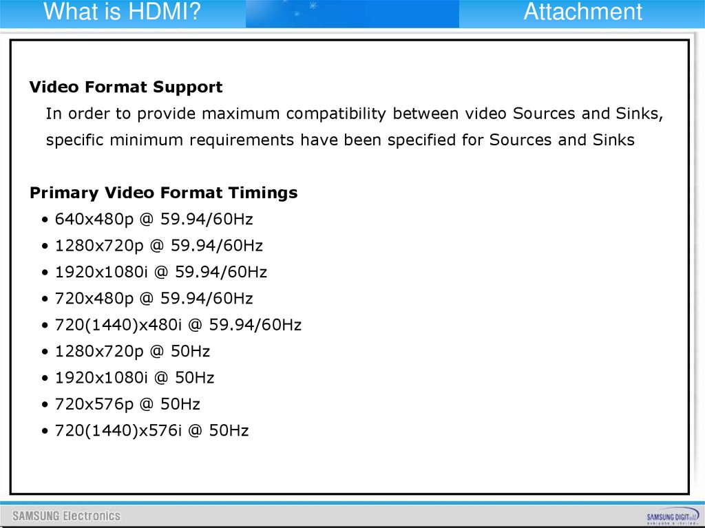
Video Format Support
In order to provide maximum compatibility between video Sources and Sinks,
specific minimum requirements have been specified for Sources and Sinks
Primary Video Format Timings
• 640x480p @ 59.94/60Hz
• 1280x720p @ 59.94/60Hz
• 1920x1080i @ 59.94/60Hz
• 720x480p @ 59.94/60Hz
• 720(1440)x480i @ 59.94/60Hz
• 1280x720p @ 50Hz
• 1920x1080i @ 50Hz
• 720x576p @ 50Hz
• 720(1440)x576i @ 50Hz
87.
What is HDMI?Attachment
Audio Sample Rates and Support Requirements
If an HDMI Source supports audio transmission across any output, then it
shall support HDMI audio transmission. If an HDMI Source supports any
HDMI audio transmission, then it shall support 2 channel L-PCM using an
IEC 60958 Subpacket structure, with either 32kHz, 44.1kHz or 48kHz
sampling rate and a sample size of 16 bits or more.
An HDMI Source is permitted to transmit L-PCM or encoded audio data at
sample rates of 32kHz, 44.1kHz, 48kHz, 88.2kHz, 96kHz, 176.4kHz and
192kHz using either IEC 60958 format or IEC 61937 format. If an HDMI
Sink supports audio reception across any input, then it shall support
audio reception from all HDMI inputs.
Basic Audio. is defined as two channel L-PCM audio at sample rates of
32kHz, 44.1kHz, or 48kHz, with a sample size of at least 16 bits. For
EIA/CEA-861B references to DTV devices, .Basic Audio. is defined as two
channel L-PCM audio at sample rates of 32kHz, 44.1kHz, and 48kHz.
There is no sample size usage restriction for DTV devices. An HDMI Sink
may optionally accept audio at sample rates of 88.2kHz, 96kHz, 176.4kHz
and/or 192kHz using either IEC 60958 format or IEC 61937 format, and
should indicate these capabilities in the E-EDID data structure.
88.
What is HDMI?Attachment
Compatibility With DVI
All HDMI Sources shall be compatible with DVI 1.0 compliant sink devices (i.e.
“monitors” or “displays”) through the use of a passive cable converter. Likewise,
all HDMI Sinks shall be compatible with DVI 1.0 compliant sources (i.e. “systems”
or “hosts”) through the use of a similar cable converter.
When communicating with a DVI device, an HDMI device shall operate according
to the DVI 1.0 specification, with the following exception - these devices are not
required to comply with DVI 1.0 rules regarding:
• Monitor scaling requirements
• Physical Interconnect specifications
• System Low Pixel Format Support Requirements
Furthermore, for HDMI devices which do not have a “BIOS” or “operating system”,
there are the following additional exceptions:
• “BIOS” requirements
• “Operating system” requirements
• “System level event” requirements
• Power management requirements
89.
What is TXT?Attachment
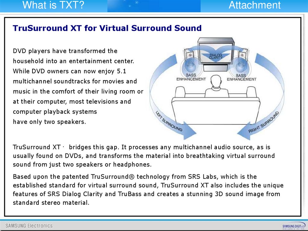
TruSurround XT for Virtual Surround Sound
DVD players have transformed the
household into an entertainment center.
While DVD owners can now enjoy 5.1
multichannel soundtracks for movies and
music in the comfort of their living room or
at their computer, most televisions and
computer playback systems
have only two speakers.
TruSurround XT bridges this gap. It processes any multichannel audio source, as is
usually found on DVDs, and transforms the material into breathtaking virtual surround
sound from just two speakers or headphones.
Based upon the patented TruSurround® technology from SRS Labs, which is the
established standard for virtual surround sound, TruSurround XT also includes the unique
features of SRS Dialog Clarity and TruBass and creates a stunning 3D sound image from
standard stereo material.
90.
What is TXT?Attachment
TruSurround XT features
TruSurround: TruSurround is a patented SRS technology that solves the problem of
playing 5.1 multichannel content over two speakers. TruSurround delivers a compelling,
virtual surround sound experience through any two-speaker playback system, including
internal television speakers and headphones. It is fully compatible with all multichannel
formats up to 6.1 channels.
SRS Dialog Clarity Enhancement: Playback of dialog often suffers due to competing
signals from other speakers. In addition, feature film soundtracks are mixed specifically for
cinema playback and are loaded with the latest advancements in special audio effects.
When translated over home theatre or computers systems, dialog may become
unintelligible. This patented SRS algorithm enhances signal clarity to address these
problems, thus improving dialog intelligibility from all such source material.
91.
What is TXT?Attachment
TruSurround XT features
TruBass: TruBass is a patented SRS technology that enhances bass performance utilizing
proprietary psychoacoustic techniques. These techniques restore the perception of
fundamental low frequency tones by dynamically augmenting harmonics, which are more
easily reproduced by contemporary loudspeakers.
Using TruBass, TruSurround XT takes the bass information contained within the original
audio track and helps the speakers or headphones re-create it – even if it is below the
speaker’s low frequency limitations.
WOW: WOW™ is an award winning stereo enhancement technology that significantly
improves the performance of stereo (non-surround sound encoded material) signals
through any two-speaker system, including headphones. It extends the sound image in
both the horizontal and vertical planes well beyond the speakers themselves. In addition,
WOW incorporates TruBass and SRS Dialog Clarity Enhancement.
When TruSurround XT accepts a stereo signal, WOW is enabled for a better listening
experience. Wow is also used by Microsoft in their new Media Player for Windows XP and
Windows Media Player 7.