


)")
)")


 Электроника
Похожие презентации:


SVC Mode Menus. How to use the Adjustment Remote Controller
1. SVC Mode Menus
How to use theAdjustment Remote Controller
SVC Mode Menus
1 / 41
2. EZ ADJUSTMENT MENUS
1.1. YouYouneed
needan
anLG
LGADJUST
ADJUSTRemote
RemoteP/N
P/N105-201M
105-201M(new
(newService
Service
remote
MKJ39170828)
remote MKJ39170828)
2.2. Press:
Press:“ADJ”
“ADJ”
3.3. Default
Defaultpassword
passwordtotoenter
enterthe
theSVC
SVCmenu:
menu:“0413”
“0413”(or
(orelse
elsetry:
try:“0000”)
“0000”)
LG ADJUST REMOCON 105-201M
2 / 41
3. EZ ADJUST
TheTheEZ-ADJUST
EZ-ADJUSTmenu
menudisplays
displaysup
uptoto18
18sub-menus
sub-menusfor
forthe
the
engineer
engineertotocheck
checkand
andadjust
adjustfinal
finalTV
TVsettings.
settings.Please
Pleasenote
note
that
thatwe
weshow
showonly
onlythe
theLCD
LCDrelated
relateditems
itemsand
andthat
thatthe
theADJ
ADJ
menus
menusmay
maybe
bedifferent
differentper
pereach
eachmodel.
model.
EZ ADJUST
0.Tool Option1
1.Tool Option2
2.Tool Option3
3.Tool Option4
4.Tool Option5
5.Country Group
6.Area Option
7.ADC Calibration
8.White Balance
9. 10 Point WB
10.Test Pattern
11.EDID D/L
12. Sub B/C
13. V-Com
14. P-Gamma
15. ACAP PING Test
16. Module Control
17. Temperature Threshold
18. Touch Sensitivity Setting
Analog
Analogonly*
only*
Korea
Korea only*
only*
PDP
PDPmodels
modelsonly*
only*
* We will not show these items any more after this slide.
3 / 41
4. Tool Option1
TheTheSVC
SVCTool
ToolOption
Option11menu
menudisplays
displaysaanumber
numberofof
items
that
generally
describe
the
TV
items that generally describe the TVmodel:
model:
• •A number of five digits
A number of five digits
•Tool
•ToolOption
Option11has
hasfour
foursub-items
sub-items
EZ ADJUST
0.Tool Option1
1.Tool Option2
2.Tool Option3
3.Tool Option4
4.Tool Option5
5.Country Group
6.Area Option
7.ADC Calibration
8.White Balance
9. 10 Point WB
10.Test Pattern
11.EDID D/L
12. Sub B/C
13. V-Com
14. P-Gamma
15. Touch Sensitivity Setting
Tool Option1
Tool Option1
Inch
Tool
Maker
Module Rev.
Inch
Inch(4bit):
(4bit):
Tool
Tool(7bit):
(7bit):
24742
24742
42
42
LG70
LG70
LGD
LGD
0
0
19,
19,22,
22,26,
26,32,
32,37,
37,42,
42,47,
47,52,
52,....
LA20,
LA20,LA30,
LA30,LA40,
LA40,….
….
Maker
Module
Maker(3bit)
(3bit): :
ModuleMaker
Maker(LGD,
(LGD,AUO,
AUO,…)
…)
Module
ModuleRev
Rev(2bit):
(2bit):Info
Infoon
onModule
ModuleVersion
Version
You can return to the EZ ADJUST main menu by pressing the ADJ button
4 / 41
5. Tool Option2
• •A number of five digitsA number of five digits
•Tool
•ToolOption
Option22has
hasaanumber
numberofofsub-items
sub-items
The
TheSVC
SVCTool
ToolOption
Option22menu
menudisplays
displaysthe
the
input
inputand
andoutput
outputjacks
jacksand
andtheir
theirlocation.
location.
EZ ADJUST
0.Tool Option1
1.Tool Option2
EZ ADJUST
2.Tool Option3
3.Tool Option4
4.Tool Option5
5.Country Group
6.Area Option
7.ADC Calibration
8.White Balance
9. 10 Point WB
10.Test Pattern
11.EDID D/L
12. Sub B/C
13. V-Com
14. P-Gamma
15. Touch Sensitivity Setting
Tool Option2
Tool Option2
HDMI Count
HDMI Switch IC
HDMI Position
Component Count
CompPosition
CompAV Common
Comp Swap
Scart Count
RCA AV Count
RCA AV Position
RGB Count
USB count
54695
54695
3
3
NONE
NONE
Rear
Rear
1
1
Rear
Rear
OFF
OFF
OFF
OFF
Full
Full
1
1
Rear
Rear
1
1
0
0
5 / 41
Tool Option
bi
ts
HDMI Count
2
0/1/2/3
HDMI input number. Minimum 1 unit
1:1 EA 2:2EA 3:3EA 4:4EA
HDMI Switch
IC
1
0/1/2/3/4
Type of HDMI Switch IC.
0:None 1:GPIO 2:PS 3:TDA 4:
SI
HDMI Position
1
Rear/
Side
HDMI Position (Rear/Side)
HDMI 1 : rear or side
HDMI 2 : rear or side
HDMI 3 : rear or side
HDMI 4: always on side
Component
Count
2
0/1/2/3
Number of Component inputs
Comp Position
1
0/1
Jack position (Rear/Side) in case of 1
Component input
Comp AV
Common
1
OFF/ON
Component/AV jack or not
(Component 2 only )
Comp Swap
1
OFF/ON
Component 1, 2 : Swap classification
SCART Count
1
None/
Full/
SCART input No.. AV1,2,3 input name
are assigned the SCART prior to
RCA AV.
(None : Full )
RCA AV
Count
2
0/1/2/3
Number of RCA input jacks except for
SCART
RCA AV
Position
1
Rear/
Side
AV Jack position (Rear/Side)
RGB Count
1
0/1
Number of RGB inputs
USB Count
1
1/2
Number of USB ports
Range
Remark (UI display)
6. Tool Option3
• •A number of three digitsA number of three digits
•Tool
•ToolOption
Option33has
hasaanumber
numberofofsub-items
sub-items
The
TheSVC
SVCTool
ToolOption
Option33menu
menudisplays
displaysaa
number
numberofofcapabilities
capabilitiesofofthe
theTV.
TV.
EZ ADJUST
ADJUST
0.ToolEZ
Option1
1.Tool Option2
2.Tool Option3
3.Tool Option4
4.Tool Option5
5.Country Group
6.Area Option
7.ADC Calibration
8.White Balance
9. 10 Point WB
10.Test Pattern
11.EDID D/L
12. Sub B/C
13. V-Com
14. P-Gamma
15. Touch Sensitivity Setting
Tool Option3
Tool Option3
EMF(JPEG,MP3)
Divx
Bluetooth
Digital Eye
Headphone
E-Manual
Audio Amp
Backlight Type
Wireless Ready
Boot Logo
DVR Ready
Instant Boot
493
493
1
1
0
0
1
1
0
0
0
0
1
1
NTP7000
NTP7000
CCFL
CCFL
0
0
0
0
0
0
0
0
6 / 41
Rang
e
Tool Option
bits
EMF
(JPEG,MP3)
1
0/1
EMF(JPEG,MP3) function support
0: no 1: yes
Divx
1
0/1
Divx function support
Bluetooth
1
0/1
Bluetooth function support
Digital Eye
1
0/1
Digital Eye function support
Headphone
1
0/1
Headphone function support
E-Manual
1
0/1
E-manual function support
0/1/2
Type of Audio Amp IC
0:NTP7000 1:TAS5713
2:NTP3AMP, 3 :TAS3AMP, 4:
NTP2AMP
0/1/2
Backlight type
0:CCFL 1:NOR_LED
2:EDG_LED,
3: IOP_LED
Audio Amp
3
Remark(UI display)
Backlight
Type
3
Wireless
Ready
1
0/1
Wireless Ready function support
Boot Logo
1
0/1
Boot logo function support
DVR Ready
1
0/1
DVR Ready function support
Instant Boot
1
0/1
Instant Boot function support
7. Tool Option4
TheTheSVC
SVCTool
ToolOption
Option44menu
menudisplays
displaysmore
more
capabilities
of
the
TV.
capabilities of the TV.
EZADJUST
ADJUST
EZ
ADJUST
0.Tool EZ
Option1
1.Tool Option2
2.Tool Option3
3.Tool Option4
4.Tool Option5
5.Country Group
6.Area Option
7.ADC Calibration
8.White Balance
9. 10 Point WB
10.Test Pattern
11.EDID D/L
12. Sub B/C
13. V-Com
14. P-Gamma
15. Touch Sensitivity Setting
Tool Option4
Tool Option4
Local Dimming
CIFS
DLNA
THX
Digital Demod
Analog Demod
THX Media Director
Picture Wizard
ISF
Energy Star
8448
8448
0
0
0
0
0
0
0
0
DVB_S7
DVB_S7
XC5000
XC5000
0
0
0
0
0
0
OFF
OFF
7 / 41
• •A number of four digits
A number of four digits
•Tool
•ToolOption
Option44has
hasaanumber
numberofofsub-items
sub-items
Tool Option
b
it
s
Ran
ge
Local Dimming
1
0/1
Local Dimming function support
no, 1: yes
CIFS
1
0/1
CIFS function support
DLNA
1
0/1
DLNA function support
THX
1
0/1
THX function support
Remark(UI display)
0:
Digital Demod
5
0/1/2
/3/4/.
.
Type of Digital Demodulator
0:Default,1:AT_S7, 2:AT_BCM,
3:AT_LGDT3305, 4:BR_MN884433,
5: BR_TC90517, 6:CN_LGDT3900,
7: CN_LGDT3911, 8:CN_LGS8G85, 9:
DVB_DRXK,10: DVB_SONY_T2,
11: DVB_SONY_TC,12: DVB_BCM,
13: DVB_S7,14: NO_DEMOD
Analog demod
3
0/1/2
/3/4
Type of Analog Demodulator
0:Default, 1: LGT10, 2:XC5000,
3: SANYO, 4:CHB
THX Media
Director
1
0/1
THX Media Director function support
Picture Wizard
1
0/1
Picture Wizard function support
ISF
1
0/1
ISF mode function support
Energy Star
1
0ff /
On
Energy Star function support
8. Tool Option 5
• •A number of four digitsA number of four digits
•Tool
•ToolOption
Option55has
hasaanumber
numberofofsub-items
sub-items
The
TheSVC
SVCTool
ToolOption
Option55menu
menudisplays
displaysmore
more
capabilities
of
the
TV.
capabilities of the TV.
EZADJUST
ADJUST
EZ
EZ ADJUST
0.Tool Option1
1.Tool Option2
2.Tool Option3
3.Tool Option4
4.Tool Option5
5.Country Group
6.Area Option
7.ADC Calibration
8.White Balance
9. 10 Point WB
10.Test Pattern
11.EDID D/L
12. Sub B/C
13. V-Com
14. P-Gamma
15.Touch Sensitivity Setting
Range
HDMI
Swap/Order
1
4 digits
order
1-2-3-4
1-3-2-4
2-1-4-3
1-2-4-3
Order of HDMI input port
switching to Main Chip
WiFi
1
0/1
1:Wifi function support
0:No support
Skype
1
0/1
1:Skype function support
0:No support
Motion Remote
control
1
0/1
1: Motion R/C support
0: No support
Channel
Browser
1
0/1
1: channel browser function
0: no support
Set ID
1
0/1
1: Set ID function support
0: no support
USB Hub Count
1
0/1
1: USB hub support
0: no support
Mirror Mode
1
0/1
1: Mirror mode support
0: no support
Orange Service
1
0/1
1:Orange contents support
0: no support
Netcast Service
1
0/1
1:Netcast support
0: no support
PSU Power
1
0/1
1:PSU support
0: no support
Tool Option4
8448
8448
0
0
0
0
0
0
0
0
0
0
1
1
0
0
0
0
0
0
0
0
0
0
Tool Option 5
HDMI Swap/Order
WiFi
Skype
Motion Remocon
Channel Browser
Set ID
USB Hub Count
Mirror Mode
Orange Service
Netcast Service
PSU Power
Orange
Orange(in
(inFrance)
France)
PSU = Power Supply Unit
b
it
s
Tool Option
Power
Powerboard:
board:22types
typespossible
possible
including
includingPSU
PSUpower
power
8 / 41
Remark(UI display)
9. Country Group
TheTheSVC
SVCTool
ToolOption
Option55menu
menudisplays
displaysthe
the
assigned
country
group.
assigned country group.
EZ ADJUST
EZ ADJUST
0.Tool Option1
EZ ADJUST
1.Tool Option2
2.Tool Option3
3.Tool Option4
4.Tool Option5
5.Country Group
6.Area Option
7.ADC Calibration
8.White Balance
9. 10 Point WB
10.Test Pattern
11.EDID D/L
12. Sub B/C
13. V-Com
14. P-Gamma
15. Touch Sensitivity Setting
InInEurope
Europewe
weuse
useCountry
CountryGroup
GroupCode
Code44that
thatcorresponds
correspondstoto“EU”
“EU”
(Note:
(Note:this
thisvalue
valuewill
willonly
onlychange
changeififthe
theCountry
CountryGroup
Groupisischanged)
changed)
Country Group
Country Group Code
Country Group
Country
Press (
04
04
EU
EU
---
) to save
The
TheEU
EUincludes
includes36
36different
differentcountries
countries(UK,
(UK,FR,
FR,DE,
DE,IT,
IT,SE,….
SE,…. etc)
etc)
9 / 41
10. ADC Calibration
•Mstar model: uses internal pattern for ADCcalibration via this menu
ADC Calibration
EZADJUST
ADJUST
EZ
ADJUST
0.Tool EZ
Option1
1.Tool Option2
2.Tool Option3
3.Tool Option4
4.Tool Option5
5.Country Group
6.Area Option
7.ADC Calibration
8.White Balance
9. 10 Point WB
10.Test Pattern
11.EDID D/L
12. Sub B/C
13. V-Com
14. P-Gamma
15. Touch Sensitivity Setting
ADC = Analog-to-Digital Converter
RGB = Red-Green-Blue color coding
Comp = composite
ADC Calibration
ADC Comp 480I
NG
ADC Comp 1080p
NG
ADC RGB
NG
Start
Start
•BCM model: needs external pattern for
ADC Calibration so this menu is not
activated. Use “External ADC” menu and
connect a color pattern signal to the
Component 1 input.
Reset
Reset
Before
Beforepressing
pressingthe
the‘Start’
‘Start’button,
button,
check
if
all
input
jacks
are
unplugged
check if all input jacks are unplugged
ADC Comp Success!!!
ADC RGB Success!!!
ADC
ADCCalibration
Calibration
ADC
ADCRF
Comp 480I
ADC
ADCAV
CompP 1080p
OK
OK
OK
OK
ADC
ADCCOMP
RGB 480I
ADC COMP 1080p
OK
OK
OK
ADC RGB
Start
Start
OK
Reset
Reset
10 / 41
When
Whencalibration
calibrationhas
hasfinished,
finished,this
this
message
box
will
be
displayed
message box will be displayed
11. White Balance
ThisThismenu
menuallows
allowsyou
youtotoadjust
adjustthe
theRGB
RGBvalues
valuesthat
thatbelong
belongtotoeach
eachofofthe
the
three
color
temperatures.
It
strongly
advised
not
to
change
WB
data
three color temperatures. It strongly advised not to change WB data
because
becauseyou
youwould
wouldneed
needspecial
specialmeasurement
measurementequipment
equipment
White Balance
EZ ADJUST
0.Tool Option1
1.Tool Option2
2.Tool Option3
3.Tool Option4
4.Tool Option5
5.Country Group
6.Area Option
7.ADC Calibration
8.White Balance
9. 10 Point WB
10.Test Pattern
11.EDID D/L
12. Sub B/C
13. V-Com
14. P-Gamma
15. Touch Sensitivity Setting
Color Temp.
R-Gain
G-Gain
B-Gain
R-Cut
G-Cut
B-Cut
Test-Pattern.
Backlight
Reset
Cool
Cool
192
192
192
192
192
192
65
65
56
56
71
71
ON
ON
100
100
To Set
To
Tochange
changethe
theColor
ColorTemp,
Temp,press
press
Left/Right
Key
Left/Right Key
[Cool
/
[Cool /Medium
Medium/ /Warm
Warm] ]
Pattern display ON / OFF
Set
SetBacklight
Backlightvalue
value0…100
0…100
Set
Settotodefault
defaultvalue
value
TV Mode (or Input mode) is changed to analog channel mode automatically
when you enter WB function. You do not need to analog channel.
11 / 41
12. 10 Point WB
ThisThismenu
menuallows
allowsadjustment
adjustmentofofthe
theinitial
initialvalues
valuesfor
forthe
theWhite
WhiteBalance
Balanceby
by
the
R&D
dept.
Please
do
not
change
them.
the R&D dept. Please do not change them.
EZ ADJUST
0.Tool Option1
1.Tool Option2
2.Tool Option3
3.Tool Option4
4.Tool Option5
5.Country Group
6.Area Option
7.ADC Calibration
8.White Balance
9. 10 Point WB
10.Test Pattern
11.EDID D/L
12. Sub B/C
13. V-Com
14. P-Gamma
15.Touch Sensitivity Setting
10 Point WB
On/Off
Pattern
IRE
Luminance
Red(130.0 nit)
Green(130.0 nit)
Blue(130.0 nit)
ON
ON
Inner
Inner
100
100
130
130
0
0
0
0
0
0
Value
Valuerepresents
representsthe
thescaling
scalingofofthe
the
composite
compositevideo
videosignal
signalluminance
luminancelevel.
level.
Range
0
~
100,
determines
the
nits
Range 0 ~ 100, determines the nitsscale
scale
for
forR,G,B
R,G,B
use
use10
10Point
PointWB
WBorornot
not(Items
(Itemsare
are
greyed
out
when
“OFF”)
greyed out when “OFF”)
Pattern
Patternon
onscreen:
screen:Inner/Outer
Inner/Outer
Luminance:
Luminance:IRE
IREisisenabled
enabledonly
onlywhen
when
IRE
IREvalue
valueisis100.
100.Range
Range50
50~~500
500
Red,
Red,Green,
Green,Blue
Blue: :R,R,G,
G,BBoffset
offsetrange
range
isis -50
-50~~+50
+50
100%
•There
two 2 types of WB (2-point and 10-point WB). The 2-point
•Thereare
are two 2 types of WB (2-point and 10-point WB). The 2-point
WB
has
already
WB has alreadybeen
beenadjusted
adjustedon
onthe
themass
massproduction
productionline.
line.
•10
•10Point
PointWB
WBAdjust
AdjustMenu
Menuvalues
valuesare
arestored
storedininthe
thePSM
PSM(Program
(Program
Status
StatusMemory)
Memory)for
forthe
theExpert
Expertmode
modeororTHX
THXmode
mode
•The stored value is composed of:
•The stored value is composed of:
- -Value from adjust menu and
Value from adjust menu and
- -Value of 10 point WB in Picture menu
Value of 10 point WB in Picture menu
12 / 41
WB = White Balance
PSM = Program Status Memory
IRE = Institute of Radio Engineers
THX = Theater mode
Nit = Luminance value = 1Cd/m2 (old)
13.
AdditionalAdditionalinformation
informationabout
aboutWB
WB
1. WB (White Balance) means equality of white in the low and high brightness areas on the screen
2. Equipment: for WB measurement you need a pattern generator (for white pattern), color analyzer etc
3. Measurement
Condition: white pattern and APL 100% status
Measurement : you should determine in the center of the screen the color coordinates [X,Y]
Condition : adjust APL to 15 [Nits]
Measurement : determine the color coordinates [X,Y]
Calculate color temperature in the CIE (Commission International De L’Eclairage)
4. Color temperature
See also: http://en.wikipedia.org/wiki/Color_temperature
- This temperature is the nearest the source light and black body temperature
- Unit is [˚K] (Kelvin Degree)
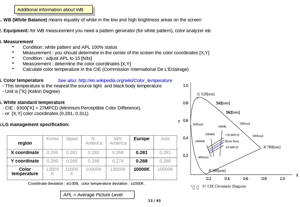
5. White standard temperature
- CIE : 9300[˚K] + 27MPCD (Minimum Perceptible Color Difference).
- or [X,Y] color coordinates (0.281, 0.311)
region
Japan
G 520[nm]
0.8
Y 0.6
N.
America
M/S
America
540[nm]
560[nm]
6.LG management specification:
Korea
1.0
Europe
Asia
0.4
500[nm]
5000K
10000K
20000K
580[nm]
+50 MPCD
600[nm]
Black Body
R 780[nm]
-10 MPCD
X coordinate
0.266
0.281
0.282
0.268
0.281
0.281
Y coordinate
0.280
0.288
0.288
0.274
0.288
0.288
Color
temperature
13000
K
10000
K
10000K
13000K
10000K
10000K
0.2
480[nm]
B 380[nm]
0.2
Coordinate deviation : ±0.008, color temperature deviation : ±1000K.
0.4
0.6
<그 그 5> CIE Chromatic Diagram
APL = Average Picture Level
13 / 41
0.8
1.0
X
14. Test Pattern
ThisThismenu
menuallows
allowsyou
youtotodisplay
displayaatest
testpattern
patternininthe
thecolor
colorofofyour
yourchoice
choice
EZ ADJUST
EZ ADJUST
0.Tool Option1
1.Tool Option2
2.Tool Option3
3.Tool Option4
4.Tool Option5
5.Country Group
6.Area Option
7.ADC Calibration
8.White Balance
9. 10 Point WB
10.Test Pattern
11.EDID D/L
12. Sub B/C
13. V-Com
14. P-Gamma
15. Touch Sensitivity Setting
Test Pattern
Pattern Control
Press Enter to hide OSD
Off
Off
•To
•Tochange
changethe
theColor
ColorTemp,
Temp,press
pressLeft/Right
Left/RightKey
Key
[ [Off
White
Red
Green
Blue
Black
Off White Red Green Blue Black] ]
•Aspect
•Aspectratio
ratioisischanged
changedtoto16:9
16:9during
duringdisplay
displayofofthe
theTest
Test
Pattern
(fills
whole
screen)
Pattern (fills whole screen)
OSD = On-Screen Display
14 / 41
15. EDID D/L
ThisThismenu
menuallows
allowsyou
youtotodownload
downloadEDID
EDIDdata
datafor
foreach
eachofofthe
theports
ports
EZ ADJUST
EZ
ADJUST
0.Tool Option1
1.Tool Option2
2.Tool Option3
3.Tool Option4
4.Tool Option5
5.Country Group
6.Area Option
7.ADC Calibration
8.White Balance
9. 10 Point WB
10.Test Pattern
11.EDID D/L
12. Sub B/C
13. V-Com
14. P-Gamma
15. Touch Sensitivity Setting
Number
NumberofofHDMI
HDMIports
portsdepends
dependson
onthe
themodel
model
EDID D/L
EDID D/L
HDMI1
NG
HDMI1
Writing…
HDMI2
NG
HDMI2
Writing…
HDMI3
NG
HDMI3
Writing…
HDMI4
NG
HDMI4
Writing…
RGB
NG
RGB
Writing…
Start
Start
Reset
Reset
Reset
Reset
EDID D/L
With
Withthe
thelatest
latestTV
TVmodels,
models,the
theEDID
EDIDdata
dataisis
included
in
the
Main
SW
load
and
must
included in the Main SW load and mustbe
be
downloaded
to
the
EDID
Memory
via
this
downloaded to the EDID Memory via this
menu.
menu.
With
Witholder
oldermodels,
models,EDID
EDIDdata
datawas
wasdownloaded
downloaded
from
fromGSFS
GSFSand
andinserted
insertedvia
viaan
anUSB
USBstick
stickororaa
special jig.
special jig.
HDMI1
OK
HDMI2
OK
HDMI3
OK
HDMI4
OK
RGB
OK
Start
Start
EDID = Extended Display Identification Data
D/L = Download
Start
Start
15 / 41
Reset
Reset
16. Sub B/C
ThisThismenu
menuallows
allowsyou
youtotoadjust
adjustthe
thebrightness
brightness
and
contrast
control
range
and contrast control range
EZ ADJUST
EZ ADJUST
0.Tool Option1
1.Tool Option2
2.Tool Option3
3.Tool Option4
4.Tool Option5
5.Country Group
6.Area Option
7.ADC Calibration
8.White Balance
9. 10 Point WB
10.Test Pattern
11.EDID D/L
12. Sub B/C
13. V-Com
14. P-Gamma
15. Touch Sensitivity Setting
Sub
SubBrightness/Contrast
Brightness/Contrastadjustment
adjustment
Global
range:
0~255
Global range: 0~255
Initial
Initialvalue:
value:128
128
Sub B/C
Sub Bright
Sub Contrast
128
10
128
10
128
128
Brightness
Brightness/contrast
/contrastvalue
valueininthe
themain
mainmenu
menuis:is:
user
adjustment
value
+
sub
data
user adjustment value + sub data
For
Forexample
example(contrast):
(contrast):
Condition
Condition: :1)1) 10
10(contrast
(contrastininmain
mainmenu)
menu)
2)2) Sub
contrast
change
128
Sub contrast change 128->->138
138
Result:
Result:10
10(contrast
(contrastininmain
mainmenu)
menu) Contrast
Contrast
data
is
10.2
in
the
internal
contrast
data is 10.2 in the internal contrastdata
data
B/C = Brightness / Contrast
16 / 41
17. V-Com – only for models that have their T-CON function on the Main Bd
ThisThismenu
menuallows
allowsyou
youtotoadjust
adjustthe
theV-Com
V-Comvalue
value
EZ ADJUST
EZ ADJUST
0.Tool Option1
1.Tool Option2
2.Tool Option3
3.Tool Option4
4.Tool Option5
5.Country Group
6.Area Option
7.ADC Calibration
8.White Balance
9. 10 Point WB
10.Test Pattern
11.EDID D/L
12. Sub B/C
13. V-Com
14. P-Gamma
15. Touch Sensitivity Setting
• •Input mode will change to analog input when you enter the V-Com menu
Input mode will change to analog input when you enter the V-Com menu
• •Screen shows a green pattern.
Screen shows a green pattern.
• •Adjust V-Com for a minimum of flicker
Adjust V-Com for a minimum of flicker
- -Range:
Range:0~1023
0~1023
- -Initial
value
Initial valueisisset
setininEEPROM
EEPROMofofMain
Mainboard
board
• •New value is stored in EEPROM when pressing the “Enter” key
New value is stored in EEPROM when pressing the “Enter” key
V-Com
440
440
V-COM
Press (
) to save
Note: contrast and color saturation will decrease for small
and large values of V-COM, for example at 110 and 680
17 / 41
18. P-Gamma control (only for >120Hz models and if FRC Chip is not PWIZ (MStar))
P-Gamma control (only for >120Hz models and if FRC Chip is not PWIZ (MStar))This
Thismenu
menuallows
allowsadjustment
adjustmentofofthe
theGamma
Gammacurve
curveand
and
store
the
new
curve
in
EEPROM.
Don’t
change
it.
store the new curve in EEPROM. Don’t change it.
EZ ADJUST
EZ Option1
ADJUST
0.Tool
1.Tool Option2
2.Tool Option3
3.Tool Option4
4.Tool Option5
5.Country Group
6.Area Option
7.ADC Calibration
8.White Balance
9. 10 Point WB
10.Test Pattern
11.EDID D/L
12. Sub B/C
13. V-Com
14. P-Gamma
15. Touch Sensitivity Setting
PG1
P-Gamma adjustment
- range: 0~1023
- initial value is set in EEPROM
P-Gamma
EZ ADJUST
0
0
0
0
0
0
0
0
PG2
PG3
PG4
PG5
PG6
PG7
PG8
0
0
0
0
0
0
0
0
PG9
PG10
PG11
PG12
Store
Store
Pattern
Patternisisdefault.
default.Please
Pleasedo
donot
notchange
changethis.
this.Pattern
Patternwill
willbe
be
changed
changedautomatically
automaticallywhen
whenyou
youmove
movethe
thecursor.
cursor.
Pattern
Patternchange
changeisisused
usedfor
forprecise
preciseGamma
Gammaadjustment
adjustment
Gamma : see http://en.wikipedia.org/wiki/Gamma_correction
18 / 41
P-Gamma values are stored EEPROM when
pushing the “Enter” key
< Pattern >
PG1 , PG12 : 255 Gray
PG2, PG11 : 223 Gray
PG3, PG10 : 191 Gray
PG4, PG9 : 64 Gray
PG5, PG8 : 31 Gray
PG6, PG7 : 0 Gray
< P-Gamma ID Address >
PG2 : 0x2
PG3 : 0x3
PG4 : 0x4
PG5 : 0x5
PG8 : 0x6
PG9 : 0x7
PG10 : 0xB
PG11 : 0xC
PG1, 6, 7, 12 have been reserved (beyond
control)
19. P-Gamma control (for >240Hz models in case FRC Chip is PWIZ (MStar))
P-Gamma control (for >240Hz models in case FRC Chip is PWIZ (MStar))This
Thismenu
menuallows
allowsadjustment
adjustmentofofthe
theGamma
Gammacurve
curveand
and
store
the
new
curve
in
EEPROM.
Don’t
change
it.
store the new curve in EEPROM. Don’t change it.
EZ ADJUST
EZ Option1
ADJUST
0.Tool
1.Tool Option2
2.Tool Option3
3.Tool Option4
4.Tool Option5
5.Country Group
6.Area Option
7.ADC Calibration
8.White Balance
9. 10 Point WB
10.Test Pattern
11.EDID D/L
12. Sub B/C
13. V-Com
14. P-Gamma
15. Touch Sensitivity Setting
PG1
P-Gamma
EZ ADJUST
PG2
PG3
PG4
PG5
PG6
PG7
PG8
PG9
PG10
PG11
PG12
PG13
PG14
PG15
PG16
Pattern
Patternisisdefault.
default.Please
Pleasedo
donot
notchange
changethis.
this.Pattern
Patternwill
willbe
be
changed
changedautomatically
automaticallywhen
whenyou
youmove
movethe
thecursor.
cursor.
Pattern
Patternchange
changeisisused
usedfor
forprecise
preciseGamma
Gammaadjustment
adjustment
19 / 41
• P-Gamma adjustment
- range: 0~1023
- initial value is set in EEPROM of V-Com Bd.
0
0
0
0
0
0
0
0
0
0
0
0
0
0
0
0
0
0
0
0
0
0
0
0
0
0
0
0
0
0
0
0
Store
Store
•P-Gamma values are stored EEPROM when
pushing the “Enter” key
< Pattern >
PG1 , PG16 : 255 Gray
PG2, PG15 : 254 Gray
PG3, PG14 : 223 Gray
PG4, PG13 : 191 Gray
PG5, PG12 : 127 Gray
PG6, PG11 : 63 Gray
PG7, PG10 : 31 Gray
PG8, PG9 : 0 Gray
< P-Gamma ID Address >
PG1 : 0x0 PG9 : 0x8
PG2 : 0x1 PB10 : 0x9
PG3 : 0x2 PB11 : 0xa
PG4 : 0x3 PB12 : 0xb
PG5 : 0x4 PB13 : 0xc
PG6 : 0x5 PB14 : 0xd
PG7 : 0x6 PB15 : 0xe
PG8 : 0x7 PB16 : 0xf
20. Touch Sensitivity Setting – Only for models that have touch control
ThisThismenu
menuallows
allowsyou
youtotoadjust
adjustthe
thesensitivity
sensitivityofofthe
the
touch
keys.
Only
for
test
by
engineer.
touch keys. Only for test by engineer.
EZ ADJUST
EZ ADJUST
0.Tool Option1
1.Tool Option2
2.Tool Option3
3.Tool Option4
4.Tool Option5
5.Country Group
6.Area Option
7.ADC Calibration
8.White Balance
9. 10 Point WB
10.Test Pattern
11.EDID D/L
12. Sub B/C
13. V-Com
14. P-Gamma
15. Touch Sensitivity Setting
For LCD
Data
Datarange
rangeisis00~~255
255(1byte)
(1byte)
Touch Sensitivity Setting
KEY
Touch
POWER
0
INPUT
0
MENU
0
OK
0
VOL+
0
VOL-
0
CH+
0
CH-
0
Count Time
Global THR
THR
0
0
0
0
0
0
0
0
0
0
0
0
0
0
0
0
0
0
0
0
When
Whenyou
youtouch
touchaabutton
buttonon
onthe
thefront
frontpanel,
panel,the
the“Touch”
“Touch”
value
is
displayed
in
the
SVC
menu
value is displayed in the SVC menu
THR : Threshold
20 / 41
For
Forexample:
example:you
youtouch
touchan
aninput
inputkey,
key,input
inputvalue
valueofofthe
the
”Touch” will be displayed, e.g. 20.
”Touch” will be displayed, e.g. 20.
..
• • Value 0 of the “THR” is the most sensitive and value
Value 0 of the “THR” is the most sensitive and value
20
20isisthe
themost
mostinsensitive
insensitive
•
IfIfyou
adjust
the
you adjust the“THR”
“THR”value
valueover
over20,
20,the
thetouch
touch
sensor
sensorwon’t
won’twork
work
21. IN-START MENUS
TheTheIN-START
IN-STARTmenu
menudisplays
displayssystem
systeminformation
informationand
andsub-menus
sub-menusfor
forthe
the
engineer.
engineer.Please
Pleasenote
notethat
thatthe
themenus
menusmay
maybe
bedifferent
differentfor
foreach
eachmodel.
model.
Please
Pleasenote
notethat
thatwe
weshow
showonly
onlythe
theLCD
LCDrelated
relateditems
itemsand
andthat
thatthe
themenus
menus
may
maybe
bedifferent
differentper
pereach
eachmodel.
model.
LG ADJUST REMOCON 105-201M
21 / 41
22. IN START MENU
ThisThismenu
menuallows
allowsyou
youtotocheck
checkand
andchange
changevarious
varioussettings
settings
IN
INSTART
START
Debug Status
Debug Status
Total
TotalPanel
PanelUse
UseTime
Time(hr)
(hr)
PQL
PQLDB
DB
URSA = MStar Frame Rate
Controller chip
1. Adjust Check
IN START
2. ADC Data
3. Power Off Status
4. System1
5. System2
6. Model Number D/L
7. Test Option
8. External ADC
9. Bluetooth Test
10. Bluetooth AV CODEC Cfg.
11. Spread Spectrum
12. Sync Level
13. Wireless Ready
Chip
type
ChipCount
type
14. Stable
15. ODC Test
16. Local Dimming
EDID = Extended Display
Information Data
Model
Name
42LH20-UA
Model
Name ::42LH7000-ZA
BT = BlueTooth
Serial
Number : :V01.10.00
SKJY0104
S/W Version
S/W
Version
:
1.10.00.00
MICOM Version : V01.10
MAC = Media Access Control
MICOM
: 0.10.4
UTT : 0Version
SPI = Serial Peripheral Interface
SPI
Version: V00.01
: V00.01
UI BOOT
Res. Version
URSA
: 0.00Home
PQL DB = Picture Quality Level
AutoVersion
Store Mode : Auto
LED
Version
:
1
Data Base
Maker :00
EDID Version (RGB) : 1.01
UTT = Usage total Time
EDID Version (HDMI) : 1.01
ESN = Electronic Serial Number
BT S/W version
: 1.22
BT H/W version
: 3164
PCB mode = Printed Circuit
Chip Type
: SATURN 7
Board (for production process)
Wireless Host Ver.
: 1.02.1
Wireless B/B Ver.
: 0.01.1
Wi-Fi Version
: 1.0
Wi-Fi Channel
:0
Wi-Fi:
Wi-Fi:Version,
Version,Channel
Channel&&MAC
MACAddress*
Address*
Wi-Fi MAC : 00:ED:91:C6:C7:92
MAC
MAC Address : FE:22:56:43:00:55
MACAddress*
Address*
ESN Num.:ESN-LH50000300100ECEB2
Netflix
NetflixESN
ESNNumber**
Number**
Debug Status
: EVENT
Local Dimming Ver. : 0x0702
Local
LocalDimming
DimmingVersion
Version
UTT : 0
Application Revision Number
APP History Ver. : 8445
Application Revision Number
PQL DB : LGD_CF_LGT10_xxxxxx
Substrate
“Substrate
“SubstrateMode”
Mode” isisdisplayed
displayedininPCB
PCBmode
mode
Mode
** Only for models that support Netflix. The LG Device uses the ESN number to
communicate with the Netflix server. This number is automatically validated during
the handshake between the LG Device and Netflix service
22 / 41
*Only for models that support networking
23. IN START MENU
ThisThissub
submenu
menuallows
allowsyou
youtotocheck
checkand
andchange
changevarious
varioussettings
settings
IN
INSTART
START
Model
Name
42LH20-UA
Model
Name ::42LH7000-ZA
Serial
Number : :V01.10.00
SKJY0104
S/W Version
S/W
Version
: 1.10.00.00
MICOM Version : V01.10
MICOM
: 0.10.4
UTT : 0Version
SPI
Version: V00.01
: V00.01
UI BOOT
Res. Version
URSA
Version
:
0.00Home
Auto Store Mode : Auto
LED
Version
:1
Maker
:00
EDID Version (RGB) : 1.01
EDID Version (HDMI) : 1.01
BT S/W version
: 1.22
BT H/W version
: 3164
Chip Type
: SATURN 7
Wireless Host Ver.
: 1.02.1
Wireless B/B Ver.
: 0.01.1
Wi-Fi Version
: 1.0
Wi-Fi Channel
:0
Wi-Fi MAC : 00:ED:91:C6:C7:92
MAC Address : FE:22:56:43:00:55
ESN Num.:ESN-LH50000300100ECEB2
Debug Status
: EVENT
Local Dimming Ver. : 0x0702
1. Adjust Check
IN START
2. ADC Data
3. Power Off Status
4. System1
5. System2
6. Model Number D/L
7. Test Option
8. External ADC
9. Bluetooth Test
10. Bluetooth AV CODEC Cfg.
11. Spread Spectrum
12. Sync Level
13. Wireless Ready
14. Stable Count
15. ODC Test
16. Local Dimming
UTT : 0
APP Histroy Ver. : 8445
PQL DB : LGD_CF_LGT10_xxxxxx
Substrate
Mode
Bluetooth
Bluetoothmodels
modelsonly
only
Wireless
WirelessReady
Readymodels
modelsonly
only
ADC = Analog to Digital Converter
D/L = Down Load
ODC = Over Driving Control
23 / 41
24. Adjust Check
ThisThismenu
menuallows
allowsyou
youtotocheck
checkand
andadjust
adjustvarious
varioussettings.
settings.The
The
orange
colored
values
were
inserted
during
manufacturing
orange colored values were inserted during manufacturing
IN START
1. Adjust Check
2. ADC Data
Model Name
: 42LH20-UA
3. Power Off Adjust
Status Check
Serial Number : SKJY0104
4.
System1
S/W Version
: 1.10.00.00
5. System2
MICOM Version
: 0.10.4
6. Model Number D/L
SPI BOOT Version : V00.01
7. Test Option
URSA Version
: 0.00
8. External ADC
LED Version
:1
9. Bluetooth Test
EDID Version (RGB) : 1.01
10. Bluetooth AV CODEC Cfg.
EDID Version (HDMI) : 1.01
11. Spread Spectrum
BT S/W version
: 1.22
12. Sync Level
BT H/W version
: 3164
13. Wireless Ready
Maker :00
1.
“Country
Group”
selection;
you
can
make
Wireless
Host Version
: 1.02.1 you 14.
1. “Country
Group” selection;
canStable
makeCount
changes
from
are
15.
ODC Test
Wireless
B/B Version
: too
0.01.1
changes
fromhere
here
tooand
andthey
they
are
stored
real-time
16.
Local Dimming
stored real-time
UTT : 0
2.
values;
APP
Histroy
Ver.
: 8445you
2. Tool
ToolOption
Option
values;
youcan
canmake
make
from
here
PQLchanges
DB
:
LGD_CF_LGT10_xxxxxx
changes from here
3.3. Result
ResultofofWhite
WhiteBalance
Balanceadjustment
adjustment
4.4. Adjustment
Adjustmentresult
resultofofauto
autoADC
ADC
adjustment for each input mode
adjustment for each input mode
5.5. EDID
EDIDdata
dataloaded
loadedor
ornot
not
6.6. CI+
CI+key:
key:EU
EUOnly
Only
24 / 41
Adjust Check
1. Country Group ( Press OK to Save )
02
Country Group Code
02
US
Country Group
US
Country
US
US
2. Tool Option
0
0
Tool Option1
24640
Tool Option2
24640
30914
Tool Option3
30914
48256
Tool Option4
48256
8448 OK
3. Adjust White Balance :
8448
4. Adjust ADC :
OK
480i Component
OK
1080p Component
OK
RGB
OK
OK
5. EDID :
OK OK
OK
RGB
HDMI1
NG(0x71)
NG(0x71)
HDMI2
NG(0x1D,0xCE)
NG(0x1D,0xCE)
HDMI3
NG(0x1C,0xCD
NG(0x1C,0xCD
HDMI4
NG(0x1A,0xCF
NG(0x1A,0xCF
6. CI+ Key :
NG(0x1B,0xCE
NG(0x1B,0xCE
OK(DD204111B596A453)
25. ADC Data
ThisThismenu
menuallows
allowsyou
youtotocheck
checkand
andadjust
adjustthe
thesettings
settingsfor
for
the
Analog-to-Digital
converter
that
converts
the
analog
the Analog-to-Digital converter that converts the analog
input
inputsignals
signalsinto
intodigital
digitalvalues.
values.
IN START
Model Name : 42LH20-UA
Serial Number : SKJY0104
S/W Version
: 1.10.00.00
MICOM Version
: 0.10.4
SPI BOOT Version : V00.01
URSA Version
: 0.00
LED Version
:1
EDID Version (RGB) : 1.01
EDID Version (HDMI) : 1.01
BT S/W version
: 1.22
BT H/W version
: 3164
Maker :00
Wireless Host Version : 1.02.1
Wireless B/B Version : 0.01.1
UTT : 0
APP Histroy Ver. : 8445
PQL DB : LGD_CF_LGT10_xxxxxx
1. Adjust Check
2. ADC Data
3. Power Off Status
4. System 1
5. System 2
6. Model Number D/L
7. Test Option
8. External ADC
9. Bluetooth Test
10. Bluetooth AV CODEC Config
11. Spread Spectrum
12. Sync Level
13. Wireless Ready
14. Stable Count
15. ODC Test
16. Local Dimming
ADC Data
0.Source
1.Save to Nvram
Comp 480i
Comp 480i
2.Red Offset
3.Green Offset
4.Blue Offset
5.Red Gain
6.Green Gain
7.Blue Gain
8.Reset
ADC
ADCmanual
manualadjust
adjustmenu
menu
Comp
480i/Comp
Comp 480i/Comp
1080p/RGB
1080p/RGB
25 / 41
Off
Off
192
192
192
192
65
65
56
56
71
71
7F
7F
Off
Off
26. Power Off Status
ThisThismenu
menushows
showsyou
youthe
thelist
listofofoccasions
occasionswhen
whenthe
theTV
TVhas
hasbeen
beenswitched
switchedoff.
off.
The
history
is
very
helpful
for
trouble
shooting
in
case
the
TV
switched
itself
off
The history is very helpful for trouble shooting in case the TV switched itself off
due
duetotoan
aninternal
internalfailure.
failure.Next
Nextslide
slideshows
showsmore
moredetails
detailsfor
foreach
eachcause.
cause.
IN START
Model Name
: 42LH20-UA
Serial Number : SKJY0104
S/W Version
: 1.10.00.00
MICOM Version
: 0.10.4
SPI BOOT Version : V00.01
URSA Version
: 0.00
LED Version
:1
EDID Version (RGB) : 1.01
EDID Version (HDMI) : 1.01
BT S/W version
: 1.22
BT H/W version
: 3164
Maker :00
Wireless Host Version : 1.02.1
Wireless B/B Version : 0.01.1
1. Adjust Check
2. ADC Data
3. Power Off Status
4. System 1
5. System 2
6. Model Number D/L
7. Test Option
8. External ADC
9. Bluetooth Test
10. Bluetooth AV CODEC Config
11. Spread Spectrum
12. Sync Level
13. Wireless Ready
14. Stable Count
15. ODC Test
16. Local Dimming
UTT : 0
APP Histroy Ver. : 8445
PQL DB : LGD_CF_LGT10_xxxxxx
26 / 41
Power Off Status
0. POWER_OFF_BY_INSTOP
1. POWER_OFF_BY_SW_DN
2. POWER_OFF_BY_ACDET
3. POWER_OFF_BY_REMOTE_KEY
4. POWER_OFF_BY_5VMNT
5. POWER_OFF_BY_KEYTIMEOUT
6. POWER_OFF_BY_RESET
7. POWER_OFF_BY_KEYTIMEOUT
8. POWER_OFF_BY_KEYTIMEOUT
9. POWER_OFF_BY_KEYTIMEOUT
10. POWER_OFF_BY_REMOTE_KEY
11. POWER_OFF_BY_REMOTE_KEY
12. POWER_OFF_BY_KEYTIMEOUT
13. POWER_OFF_BY_KEYTIMEOUT
14. POWER_OFF_BY_KEYTIMEOUT
15. POWER_OFF_BY_RESET
16. POWER_OFF_BY_KEYTIMEOUT
17. POWER_OFF_BY_KEYTIMEOUT
18. POWER_OFF_BY_RESET
19. POWER_OFF_BY_KEYTIMEOUT
20. POWER_OFF_BY_ACDET
21. POWER_OFF_BY_REMOTE_KEY
Power
Powerof
of
history
history
27. Power Off Status
FactorMicom
CPU
MODE
This
Thislist
listshows
showspossible
possiblecauses
causesfor
forswitching
switchingthe
theTV
TV
off.
off.
Contents
POWER_OFF_BY_CPUCMD
Power off by CPU Command
POWER_OFF_BY_ABN
Power off by abnormal status
POWER_OFF_BY_KEYTIMEOUT
Power off when TV is not turned off during a certain time
POWER_OFF_BY_ACDET
Power off by not detecting AC (abnormal case)
POWER_OFF_BY_RESET
Power off by Micom Reset
POWER_OFF_BY_5VMNT
Power off by not detecting 5V monitoring
POWER_OFF_BY_NO_POLLING
Power off when receiving no ack
POWER_OFF_BY_REMOTE_KEY
Power off by remote key
POWER_OFF_BY_OFF_TIMER
Power off by Off timer
POWER_OFF_BY_SLEEP_TIMER
Power off by sleep timer
POWER_OFF_BY_ABNORMAL1
(POWER_OFF_BY_TS_END) – DVR Ready
Power off by abnormal status
Power off by time shift end
POWER_OFF_BY_FAN_CONTROL
Power off by fan control
POWER_OFF_BY_INSTOP_KEY
Power off by Instop Key
POWER_OFF_BY_AUTO_OFF
Power off by auto off function
POWER_OFF_BY_ON_TIMER
Power off by On timer
POWER_OFF_BY_RS232C
Power off by RS232C command
POWER_OFF_BY_RESREC
Power off by reserved recording
POWER_OFF_BY_RECEND
Power off when recording stops
POWER_OFF_BY_SWDOWN
Power off by software download
POWER_OFF_BY_LOCAL_KEY
Power off by local key
POWER_OFF_BY_CPU_ABNORMAL
Power off by CPU Abnormal status
POWER_OFF_BY_INV_ERROR
Power off by LCD module inverter error
POWER_OFF_BY_HOMING_COMPLETE
Power off by Cable Card Update (USA only)
POWER_OFF_BY_OTA
Power off by OTA update
POWER_OFF_BY_UNKNOWN
Power off by the other causes
27 / 41
28. System 1
ThisThismenu
menuallows
allowsyou
youtotocheck
checkand
andadjust
adjustvarious
varioussettings.
settings.
More
details
about
System
1
settings
are
shown
on
More details about System 1 settings are shown onthe
thenext
nextslide.
slide.
IN START
Model Name
: 42LH20-UA
Serial Number : SKJY0104
S/W Version
: 1.10.00.00
MICOM Version
: 0.10.4
SPI BOOT Version : V00.01
URSA Version
: 0.00
LED Version
:1
EDID Version (RGB) : 1.01
EDID Version (HDMI) : 1.01
BT S/W version
: 1.22
BT H/W version
: 3164
Maker :00
Wireless Host Version : 1.02.1
Wireless B/B Version : 0.01.1
1. Adjust Check
2. ADC Data
3. Power Off Status
4. System 1
5. System 2
6. Model Number D/L
7. Test Option
8. External ADC
9. Bluetooth Test
10. Bluetooth AV CODEC Config
11. Spread Spectrum
12. Sync Level
13. Wireless Ready
14. Stable Count
15. ODC Test
16. Local Dimming
UTT : 0
APP Histroy Ver. : 8445
PQL DB : LGD_CF_LGT10_xxxxxx
System 1
0. Baudrate
1. 2Hour Off(On Timer)
2. 2 Hours Off(Screen Mute)
3. 15Min Force Off
4. Audio EQ
5. Audio Bass EQ
6. A2 Threshold
7. HDMI Sound (Port1)
8. Lip Sync Adjust (DTV)
9. Dimming
10. Tuner Option
11. Atten RF Signal
12. UTT Reset
13. Channel Mute
14. Debug Status
15. NVRAM Type
16. HDEV
17. Booster On (VHF)
18. Booster Off (VHF)
19. Booster On (UHF)
20. Booster Off (UHF)
115200
115200
On
On
On
On
On
On
On
On
On
On
11
11
HDMI Port 1
HDMI Port 1
0
Variable
Variable-10…+20
-10…+20
0
On
On
Default
Default
Off
Off
Reset
Doing,
Doing,Reset
Reset
Reset
Off
Off
Event
Event
EEPROM
EEPROM
On
On
0
0
0
0
0
0
0
0
UTT = Usage Total Time
Specific Chinese items are not shown.
28 / 41
Only
Onlyfor
formodels
modelsthat
thathave
have
aabooster
booster
29. System 1
System 10. Baudrate
1. 2Hour Off(On Timer)
2. 2 Hours Off(Screen Mute)
3. 15Min Force Off
4. Audio EQ
5. Audio Bass EQ
6. A2 Threshold
7. HDMI Sound (Port1)
8. Lip Sync Adjust (DTV)
9. Dimming
10. Tuner Option
11. Atten RF Signal
12. UTT Reset
13. Channel Mute
14. Debug Status
15. NVRAM Type
16. HDEV
17. Booster On (VHF)
18. Booster Off (VHF)
19. Booster On (UHF)
20. Booster Off (UHF)
115200
115200
On
On
On
On
On
On
On
On
On
On
11
11
HDMI Port 1
HDMI Port 1
0
0
On
On
Default
Default
Off
Off
Reset
Reset
Off
Off
Event
Event
EEPROM
EEPROM
On
On
0
0
0
0
0
0
0
0
0. Baudrate :
Data Download speed
[ 2400 / 4800 / 9600 / 14400 / 19200 /
38400 / 57600 / 115200 / 460800 ]
(Default : 9600 – after Instop)
9. Dimming :
Dimming On/Off Control Function
1. 2 Hours Off(On Timer) :
TV Turns off with no any key input
during the 2hours after power on by
On timer (Default On)
11. Atten RF Signal :
Signal down for strong signal of Analog TV
2. 2 Hours Off(Screen Mute) :
TV Turns off with no any key input
during the 2 hours after Screen Mute
(Default Off)
3. 15 Min Force Off :
15 forced Power Off . (Default On)
4. Audio EQ:
5. Audio Bass EQ:
Audio (Bass) equalizer setting (Default On)
6. A2 Threshold :
A2 Threshold(0~39, Default 11)
korea only (enable)
7. HDMI Sound(Port1):
HDMI Sound Path Switching 용
(HDMI Port1/ RGB Phone Jack)
8. Lip Sync Adjust(DTV):
Audio Lip Sync adjust item
(range : -10 ~ 20)
29 / 41
10. Tuner Option :
DTV Phase/Ghost noise support
12. UTT Reset :
TV Used Time Reset function
13. Channel Mute :
Video mute or not when changing analog
Channel
( On : Mute Enable, Off : Mute Disable )
14. Debug Status :
Changing debug option status of source
15. NVRAM Type:
NVRAM Type ( EEPROM, NAND Flash)
Default : EEPROM
16. HDEV:
High Deviation On/Off control
Default : Off
Country Group : disable (in case of AASIA).
17. Booster On (VHF):
18. Booster Off (VHF) :
19. Booster On (UHF) :
20. Booster Off (UHF) :
Booster AGC Gain value setting menu
(Booster supported models only)
30. System 2
ThisThismenu
menuallows
allowsyou
youtotocheck
checkand
andadjust
adjustvarious
varioussettings
settingsfor
forSystem
System22
We use Sanyo tuner or LG Tuner
We use Sanyo
tuner orCheck
LG Tuner
1. Adjust
Items
analog
channel
Items66~12
~12for
for
analog
channeltuning.
tuning.
2.changed
ADC Data
Model Name
: 42LH20-UA
Data
value
is
accordingly
each
Data value is
changed
accordingly
eachtuner
tuner
3.
Power
Off
Status
Serial Number : SKJY0104
4. System 1
S/W Version
: 1.10.00.00
5. System 2
MICOM Version
: 0.10.4
6. Model Number D/L
SPI BOOT Version : V00.01
7. Test Option
URSA Version
: 0.00
8. External ADC
NSU mode
LED Version
:1
NSU mode
9.
Bluetooth
Test
- -User
NSU
status
EDID Version (RGB) : 1.01
Usermode
mode: 10.
:real
real
NSU
status
AV CODEC
Config
- -Engineer
:Bluetooth
NSU
EDID Version (HDMI) : 1.01
Engineermode
mode
:mode
modefor
for
NSUtest
test
11.
Spread
Spectrum
BT S/W version
: 1.22
12. Sync Level
BT H/W version
: 3164
13. Wireless Ready
Maker :00
14. Stable Count
Wireless Host Version : 1.02.1
15. ODC Test
Wireless B/B Version : 0.01.1
16. Local Dimming
IN START
System 2
0. Screen Saver Cube
1. RS-232C Control
2. SSID Control
3. Tuner Video Offset
4. VCR Format
5. Tuner CR Threshold
6. VBI Line (PAL-N)
7. NSU Mode (TV will reboot)
8. Color Killer Fix
9. H-Shaking Fix
10. H-Unstable Count
11. H-Unstable Thres. Step
12. LGT10 Color Mode
UTT : 0
APP Histroy Ver. : 8445
PQL DB : LGD_CF_LGT10_xxxxxx
99~~1:1:for
forH-sync
H-synclevel
leveladjustment
adjustment
May not exist
May not exist
SSID = Service Set IDentifier = Public name of a wireless network (not in use anymore)
VCR = Video Cassette Recorder
CR = CarRier (register value for carrier level control)
VBI = Video Blanking Interval (see http://en.wikipedia.org/wiki/Vertical_blanking_interval)
NSU = Network Software Update
LGT10 = LG tuner name
30 / 41
On
On
Off
Off
On
On
0
0
PAL60
PAL60
0
0
22 Line
Only
Onlyfor
forS-America
S-America
22 Line
User Mode
User Mode
On Dynamic or static
On
On Dynamic or static
On
4
4
50
50
Normal
Normal
31. Model Number D/L
ThisThismenu
menudisplays
displaysthe
themodel
modelname
nameand
andserial
serialnumber
numberand
andallows
allowstotomake
makechanges
changes
IN START
Model Name
: 42LH20-UA
Serial Number : SKJY0104
S/W Version
: 1.10.00.00
MICOM Version
: 0.10.4
SPI BOOT Version : V00.01
URSA Version
: 0.00
LED Version
:1
EDID Version (RGB) : 1.01
EDID Version (HDMI) : 1.01
BT S/W version
: 1.22
BT H/W version
: 3164
Maker :00
Wireless Host Version : 1.02.1
Wireless B/B Version : 0.01.1
UTT : 0
APP Histroy Ver. : 8445
PQL DB : LGD_CF_LGT10_xxxxxx
Model Number D/L
1. Adjust Check
2. ADC Data
1. Model name
GLOBAL-PLAT2
GLOBAL-PLAT2
3. Power Off Status
2. Serial Number
911KCYQ53914
4. System 1
911KCYQ53914
5. System 2
6. Model Number D/L
7. Test Option
Press OK to Save
8. External ADC
9. Bluetooth Test
10. Bluetooth AV CODEC Config
11. Spread Spectrum
12. Sync Level
•You
•Youcan
canchange
changethe
theModel
Modelname
nameand
andSerial
SerialNumber
Number
13. Wireless Ready
• •Characters following a space bar are ignored
Characters following a space bar are ignored
14. Stable Count
• •Input characters : +, -, A ~Z, 0~9, Space
Input characters : +, -, A ~Z, 0~9, Space
15. ODC Test
16. Local Dimming
31 / 41
32. Test Option
TheseTheseTest
TestOptions
Optionsare
areonly
onlyfor
fortest
testengineers
engineersand
andthe
theQE
QEtest
test
department.
Don’t
use
this
menu.
department. Don’t use this menu.
IN START
Model Name
: 42LH20-UA
Serial Number : SKJY0104
S/W Version
: 1.10.00.00
MICOM Version
: 0.10.4
SPI BOOT Version : V00.01
URSA Version
: 0.00
LED Version
:1
EDID Version (RGB) : 1.01
EDID Version (HDMI) : 1.01
BT S/W version
: 1.22
BT H/W version
: 3164
Maker :00
Wireless Host Version : 1.02.1
Wireless B/B Version : 0.01.1
UTT : 0
APP Histroy Ver. : 8445
PQL DB : LGD_CF_LGT10_xxxxxx
(For
(ForQE
QEdepartment
departmenttest)
test)
For
remote
control
key
For remote control keyvalue
valuereturn
returnininthe
the
BSI
BSIsystem
system(BSI
(BSIisisfor
forQE
QEtest
testsystem)
system)oror
UART/Drive
UART/Driveprint
Test Option
1. Adjust Check
2. ADC Data
Off
1.Auto Test
Off
3. Power Off Status
On
2.UI Time Out
4. System 1
On
Off
3.Store Mode Test
5. System 2
Off
6. Model Number D/L
7. Test Option
(For
(Forengineer
engineerand
andQE
QEdepartment)
department)
8. External ADC
UI time out control. For OSD
UI time out control. For OSD
9. Bluetooth Test
language
languagetest.
test.When
When“off”,
“off”,no
noOSD
OSD
10. Bluetooth AV CODEC Config
time
out
time out
11. Spread Spectrum
12. Sync Level
13. Wireless Ready
14. Stable Count
15. ODC Test
(For
(Forengineer
engineertest)
test)
16. Local Dimming
For
e-streamer
For e-streamertest.
test.Selects
Selectsstore
storemode
modechecking
checking
time
timefor
fortester.
tester.[On
[On: :50sec,
50sec,Off
Off: :3600sec]
3600sec]
UI= User Interface
ODC = Over Driving Control
UART= Universal Asynchronous
Receiver/Transmitter
OSD = On-Screen Display
AV = Audio Video
32 / 41
33. External ADC
ThisThismenu
menuallows
allowscalibration
calibrationof
ofthe
theADC
ADCininthe
the
BCM
chipset.
Only
for
engineers
or
the
BCM chipset. Only for engineers or the
production
productionprocess.
process.Do
Donot
notuse
usethis
thismenu.
menu.
IN START
Model Name
: 42LH20-UA
Serial Number : SKJY0104
S/W Version
: 1.10.00.00
MICOM Version
: 0.10.4
SPI BOOT Version : V00.01
URSA Version
: 0.00
LED Version
:1
EDID Version (RGB) : 1.01
EDID Version (HDMI) : 1.01
BT S/W version
: 1.22
BT H/W version
: 3164
Maker :00
Wireless Host Version : 1.02.1
Wireless B/B Version : 0.01.1
UTT : 0
APP Histroy Ver. : 8445
PQL DB : LGD_CF_LGT10_xxxxxx
1. Adjust Check
2. ADC Data
3. Power Off Status
4. System 1
5. System 2
6. Model Number D/L
7. Test Option
8. External ADC
9. Bluetooth Test
10. Bluetooth AV CODEC Config
11. Spread Spectrum
12. Sync Level
13. Wireless Ready
14. Stable Count
15. ODC Test
16. Local Dimming
33 / 41
External ADC
1. Comp 480i
2. Comp 1080p
3. RGB
External
Externalanalog
analog
sources
for
sources forADC
ADC
Pattern
Patternmust
mustbe
beprovided
providedby
byexternal
externalequipment.
equipment.
ADC
ADCcalibration
calibrationisisadjusted
adjustedautomatically
automaticallywhen
whenthe
the
input
signal
is
connected.
input signal is connected.
34. Bluetooth Test – only for models that support BT
ThisThismenu
menuallows
allowsyou
youto
tocheck
checkthe
thesettings
settingsfor
forthe
theBluetooth
Bluetoothcontrol
control
system.
It
is
recommended
not
to
change
any
of
these
items.
system. It is recommended not to change any of these items.
IN START
Model Name
: 42LH20-UA
Serial Number : SKJY0104
S/W Version
: 1.10.00.00
MICOM Version
: 0.10.4
SPI BOOT Version : V00.01
URSA Version
: 0.00
LED Version
:1
EDID Version (RGB) : 1.01
EDID Version (HDMI) : 1.01
BT S/W version
: 1.22
BT H/W version
: 3164
Maker :00
Wireless Host Version : 1.02.1
Wireless B/B Version : 0.01.1
UTT : 0
APP Histroy Ver. : 8445
PQL DB : LGD_CF_LGT10_xxxxxx
Bluetooth Test
1. Adjust Check
ON:
ON:BT
BTtest
testmode
modefor
for
BT USB Drv is connected!
2. ADC Data
binary
code
downloaded
binary code downloaded
3. Power Off Status
BT USB Drv is Open
from
fromdongle
dongle
4. System 1
5. System 2
6. Model Number D/L
Off
1. DUT
Reset
Off
Resetofofdongle
dongle
7. Test Option
Yes
2. BT Force Reset
8. External ADC
Yes
Initialisation
Yes
3. BT NVRAM Init
Initialisationofof
9. Bluetooth Test
Yes
BT
BTeqt
eqtininmenu
menu
10. Bluetooth AV CODEC Config4. BT Streaming
Start
Start
11. Spread Spectrum
Instant
5. FTP Format
JPEG
Instantaudio
audio
12. Sync Level
JPEG stream
decoding
stream decoding
13. Wireless Ready
14. Stable Count
15. ODC Test
FTP
FTPtransfer
transferformat
formatofofimage
imagefiles.
files.
16. Local Dimming
JPEG
is
the
fixed
format
for
TV
JPEG is the fixed format for TV
DUT = Device Under Test
BT = BlueTooth
NVRAM = Non-Volatile Random Access Memory
FTP = File Transfer Protocol
Drv = Driver
34 / 41
35. Bluetooth AV CODEC Config – only for models that support BT
ThisThismenu
menuallows
allowsyou
youto
tocheck
checkand
andchange
change
the
settings
for
the
audio-video
CODEC
the settings for the audio-video CODECthat
that
isisused
with
Bluetooth
(for
headset).
used with Bluetooth (for headset).
IN START
Model Name
: 42LH20-UA
Serial Number : SKJY0104
S/W Version
: 1.10.00.00
MICOM Version
: 0.10.4
SPI BOOT Version : V00.01
URSA Version
: 0.00
LED Version
:1
EDID Version (RGB) : 1.01
EDID Version (HDMI) : 1.01
BT S/W version
: 1.22
BT H/W version
: 3164
Maker :00
Wireless Host Version : 1.02.1
Wireless B/B Version : 0.01.1
UTT : 0
APP Histroy Ver. : 8445
PQL DB : LGD_CF_LGT10_xxxxxx
Bluetooth AV CODEC Cfg.
1. Adjust Check
2. ADC Data
48000
1. Sampling Frequency
48000
3. Power Off Status
STEREO
2. Channel Mode
4. System 1
STEREO
16
3. Block Length
5. System 2
16
6. Model Number D/L
4. Subbands
8
7. Test Option
8
5. Allocation Method
Loudness
8. External ADC
Loudness
9. Bluetooth Test
6. SBC Bitrate
127
127
10. Bluetooth AV CODEC Cfg.
1)1)Sampling
11. Spread Spectrum
Samplingfrequency
frequency
- -Sampling
rates
12. Sync Level
Sampling ratesare
are44.1
44.1kkoror48
48kkfor
forauthentication
authentication
- -Output
13. Wireless Ready
Outputsampling
samplingrate
rateatatthe
theTV
TVisisfixed
fixedtoto48
48kk
2)2)Channel
14. Stable Count
ChannelMode
Mode
- -Output
sound
15. ODC Test
Output soundstereo
stereoorormono
mono
- -Stereo
16. Local Dimming
Stereoisisdefault
defaultand
andsupported
supported
3)3)Block
Blocklength
length
-Block
-Blocklength
lengthisisfixed
fixedtoto16
16byte
bytefor
fordata
datatransfer
transfertotoheadset
headset
4)4)Subbands
(2~8)
Subbands (2~8)
- -The
Thenumber
numberofofaudio
audiosub
subchannel
channelbands
bandsand
andisisfixed
fixedtoto88
5)5)Allocation
AllocationMethod
Method
- -Loudness
or
Loudness orSNR
SNR
- -Fixed
Fixedtotoloudness
loudness
6)6)SBC
SBCbitrate
bitrate
- -Output
Outputbitrate
bitrateisisfixed
fixedtoto127
127kbps
kbps
SBC
SBC==Sub
SubBand
BandCoding
Coding
35 / 41
36. Spread Spectrum
This menu relates to EMI problem improvement. Either the MStarmenu
or the BCM menu will be displayed. These values are
IN START
optimized so don’t change
these items
Model Name : 42LH20-UA
1. Adjust Check
Serial Number : SKJY0104
S/W Version
: 1.10.00.00
MICOM Version
: 0.10.4
SPI BOOT Version : V00.01
URSA Version
: 0.00
LED Version
:1
EDID Version (RGB) : 1.01
EDID Version (HDMI) : 1.01
BT S/W version
: 1.22
BT H/W version
: 3164
Maker :00
Wireless Host Version : 1.02.1
Wireless B/B Version : 0.01.1
UTT : 0
APP Histroy Ver. : 8445
PQL DB : LGD_CF_LGT10_xxxxxx
2. ADC Data
3. Power Off Status
4. System 1
5. System 2
6. Model Number D/L
7. Test Option
8. External ADC
9. Bluetooth Test
10. Bluetooth AV CODEC Config
11. Spread Spectrum
12. Sync Level
13. Wireless Ready
14. Stable Count
15. ODC Test
16. Local Dimming
Spread Spectrum
1. LVDS SS Control
2. LVDS Percent (%)(1~4)
3. LVDS Period (KHz)(25~40)
1. FRC LVDS SS Control
2. Percent (%) (1~4)
3. Period (KHz) (20~40)
4. BCM LVDS SS Control
5. Percent (%)(1~4)
6. Period (KHz)(20~40)
Enable
Enable
1
1
25
25
Enable
Enable
1
1
20
20
Disable
Disable
1
1
20
20
SS
SSControl
Controlisisspread
spreadspectrum
spectrumoutput
outputorornot
not
Percent
Percentand
andPeriod
Periodare
areitems
itemsfor
forclock
clockadjustment
adjustment
EMI
EMI: :Electro
ElectroMagnetic
MagneticInterference
Interference
FRC
FRC==Frame
FrameRate
RateController
Controller
LVDS
LVDS==Low
LowVoltage
VoltageDifferential
DifferentialSystem
System
SS
=
Spread
Spectrum
SS = Spread Spectrum
BCM
BCMand
andMStar
MStarare
aretwo
twodifferent
differentchipsets
chipsets
36 / 41
MStar
model
BCM
mod
el
37. Sync Level
ThisThismenu
menuallows
allowsyou
youto
toset
setthe
thesynchronization
synchronization
level
for
the
Component
input
and
level for the Component input andthe
theHDMI
HDMIinput.
input.
IN START
Model Name
: 42LH20-UA
Serial Number : SKJY0104
S/W Version
: 1.10.00.00
MICOM Version
: 0.10.4
SPI BOOT Version : V00.01
URSA Version
: 0.00
LED Version
:1
EDID Version (RGB) : 1.01
EDID Version (HDMI) : 1.01
BT S/W version
: 1.22
BT H/W version
: 3164
Maker :00
Wireless Host Version : 1.02.1
Wireless B/B Version : 0.01.1
UTT : 0
APP Histroy Ver. : 8445
PQL DB : LGD_CF_LGT10_xxxxxx
00…31.
…31.Default
DefaultComponent
Componentsync
synclevel
levelisis13.
13.
Value
0
is
most
sensitive.
Value 0 is most sensitive.
Sync Level
1. Adjust Check
2. ADC Data
1. Component
3. Power Off Status
2. HDMI
4. System 1
5. System 2
6. Model Number D/L
7. Test Option
8. External ADC
9. Bluetooth Test
10. Bluetooth AV CODEC Config
11. Spread Spectrum
12. Sync Level
13. Wireless Ready
14. Stable Count
15. ODC Test
16. Local Dimming
HDMI
HDMI==High
HighDefinition
DefinitionMultimedia
MultimediaInterface
Interface
37 / 41
6
6
6
6
00…31.
…31.Default
DefaultHDMI
HDMIsync
synclevel
levelisis0.0.
Value
Value00isismost
mostsensitive.
sensitive.
38. Wireless Ready – only for models that support WiFi
ThisThismenu
menuallows
allowsyou
youtotocheck
checkand
andchange
changethe
theWiFi
WiFisettings.
settings.
••You
change
Youcan
can
changethe
theRF
RFFrequency
Frequencyand
andPower
PowerGain
Gain
IN
START
values
values
RF Group
RF Group
selection
selection
Wireless Ready
1. Adjust Check
Model Name
: 42LH20-UA
A. RF Group Config.
A Group
••Push
2. ADC Datavalues
A Group
OK
to
Serial
Number
: SKJY0104
Push
OKbutton
button
tostore
storethe
thechanged
changed values
B.
Media-Box
Type
ATSC
3.
Power
Off
Status
S/W Version
: 1.10.00.00
ATSC
4. System 1
MICOM Version
: 0.10.4
5. System 2
1. RF Frequency
SPI BOOT Version : V00.01
Auto
Auto
6.
Model
Number
D/L
URSA Version
: 0.00
2. RF Frequency Value
1)5190Hz/38
7. Test Option
LED Version
:1
1)5190Hz/38
3. U/L RFPower Gain
8. External ADC
EDID Version (RGB) : 1.01
Manual
Manual
9. Bluetooth Test
EDID Version (HDMI) : 1.01
4. U/L RFPower Gain Val.
20
10. Bluetooth AV CODEC Config
BT S/W version
: 1.22
20
5.
D/L
RFPower
Gain
Manual
11. Spread Spectrum
BT H/W version
: 3164
Manual
12. Sync Level
6. D/L RFPower Gain Val.
Maker :00
20
20
13. Wireless Ready
Wireless Host Version : 1.02.1
7. Link Mode
Unicast
Wireless B/B Version : 0.01.1
14. Stable Count
Unicast
You
and Media
box to see the
8. Rx MAC Address
Youshould
shouldconnect
connectwireless
wirelessdongle
dongle
Media
15.and
ODC
Testbox to see the
00:03:00:04:86:56
box connected
00:03:00:04:86:56
UTT : 0 Tx/Rx
Tx/RxMAC
MACaddresses.
addresses.IfIfno
nowireless
wireless
connectedthen
then
16. Localbox
Dimming
9. Tx MAC Address
00:03:00:04:86:56
MAC
address
will
be
displayed
as
ff:ff:ff:ff:….
APP Histroy
Ver.
: 8445
00:03:00:04:86:56
MAC
address
will be displayed as ff:ff:ff:ff:….
Press OK to save.
PQL DB : LGD_CF_LGT10_xxxxxx
• • Rx MAC address: Dongle MAC address
### Wireless Diagonostics ###
Rx MAC address: Dongle MAC address
Tx
MAC
address:
Media
box
MAC
address
Tx MAC address: Media box MAC address
- Wireless status : [Connected]
U/L
- Average SNR (dB) : [23.22]
U/L==UpLnk
UpLnk
D/L
D/L==DownLink
DownLink
RF
RF==Radio
RadioFrequency
Frequency
[24.22] [22.54] [23.65] [23.65] [22.65]
MAC = Media Access Control
MAC = Media Access Control
http://en.wikipedia.org/wiki/MAC_address
http://en.wikipedia.org/wiki/MAC_address
[67.34] [56.34] [76.43] [66.34] [70.32]
SNR
SNR==Signal
SignaltotoNoise
NoiseRatio
Ratio
BER
=
Bit
Error
Rate
BER = Bit Error Rate
RSSI
RSSI==Radio
RadioSignal
SignalStrength
StrengthIndicator
Indicator
- Average RSSI (dBm) : [65.33]
- Video BER (%) : [0.0]
38 / 41
Bit error rate (%)
Bit error rate (%)
Mediabox type
Mediabox type
selection
selection
RF Frequency
RF Frequency
selection
selection
Auto or Manual
Auto or Manual
Uplink/Downlink RF
Uplink/Downlink RF
Power Gain adjust Power Gain adjust Auto or Manual
Auto or Manual
Unicast/Broadcast
Unicast/Broadcast
Wireless
Wireless
connection
connection
status
status
Average SNR
Average SNR
(dB) per each
(dB) per each
channel
channel
Average RSSI
Average RSSI
(dBm) per each
(dBm) per each
channel
channel
39. Stable Count
ThisThismenu
menudetermines
determineshow
howlong
longthe
thesignal
signalmust
mustbe
bestable
stable(after
(afterchanging
changingthe
theinput
input
mode)
before
the
screen
muting
stops.
One
unit
is
equal
to
40
ms.
mode) before the screen muting stops. One unit is equal to 40 ms.
IN START
Model Name
: 42LH20-UA
Serial Number : SKJY0104
S/W Version
: 1.10.00.00
MICOM Version
: 0.10.4
SPI BOOT Version : V00.01
URSA Version
: 0.00
LED Version
:1
EDID Version (RGB) : 1.01
EDID Version (HDMI) : 1.01
BT S/W version
: 1.22
BT H/W version
: 3164
Maker :00
Wireless Host Version : 1.02.1
Wireless B/B Version : 0.01.1
UTT : 0
APP Histroy Ver. : 8445
PQL DB : LGD_CF_LGT10_xxxxxx
Stable Count
1. Adjust Check
2. ADC Data
3. Power Off Status
4. System 1
5. System 2
6. Model Number D/L
7. Test Option
8. External ADC
9. Bluetooth Test
10. Bluetooth AV CODEC Config
11. Spread Spectrum
12. Sync Level
13. Wireless Ready
14. Stable Count
15. ODC Test
16. Local Dimming
1.
DTV
2.
ATV
3.
SCART
4.
AV
5.
Auto AV
6.
Component
7.
RGB
8.
HDMI
9.
HDD
10. USB
11. Bluetooth
12. Media Share
13. Picture Wizard
14. Support
BB
BB==Broad
BroadBand
Band
15. BB
16. Flash
39 / 41
1
1
10
10
0
0
0
0
0
0
0
0
0
0
0
0
1
1
0
0
1
1
1
1
1
1
1
1
1
1
1
1
40. ODC Test
ThisThismenu
menuallows
allowsyou
youto
tocontrol
controlthe
thepanel
panelresponse
response
time.
time.
IN START
Model Name
: 42LH20-UA
Serial Number : SKJY0104
S/W Version
: 1.10.00.00
MICOM Version
: 0.10.4
SPI BOOT Version : V00.01
URSA Version
: 0.00
LED Version
:1
EDID Version (RGB) : 1.01
EDID Version (HDMI) : 1.01
BT S/W version
: 1.22
BT H/W version
: 3164
Maker :00
Wireless Host Version : 1.02.1
Wireless B/B Version : 0.01.1
UTT : 0
APP Histroy Ver. : 8445
PQL DB : LGD_CF_LGT10_xxxxxx
ODC Test
1. Adjust Check
Off
2. ADC Data
1. Test Enable
Off
3. Power Off Status
00…15
0
2. Table Index
…15
0
4. System 1
3. Mini LVDS Signal Level
11K
6.8K
5. System 2
6.8Koror11K
11K
11K
6. Model Number D/L
7. Test Option
8. External ADC
9. Bluetooth Test
10. Bluetooth AV CODEC Config
11. Spread Spectrum
12. Sync Level
13. Wireless Ready
ODC
ODC==Over
OverDriving
DrivingControl
Control
14. Stable Count
15. ODC Test
16. Local Dimming
40 / 41
41. Local Dimming – only for models that support Local Dimming
ThisThismenu
menuallows
allowsyou
youto
toload
loadthe
thelocal
localdimming
dimming
frmware
frmware
IN START
Model Name
: 42LH20-UA
Serial Number : SKJY0104
S/W Version
: 1.10.00.00
MICOM Version
: 0.10.4
SPI BOOT Version : V00.01
URSA Version
: 0.00
LED Version
:1
EDID Version (RGB) : 1.01
EDID Version (HDMI) : 1.01
BT S/W version
: 1.22
BT H/W version
: 3164
Maker :00
Wireless Host Version : 1.02.1
Wireless B/B Version : 0.01.1
UTT : 0
APP Histroy Ver. : 8445
PQL DB : LGD_CF_LGT10_xxxxxx
Local Dimming
1. Adjust Check
Start
2. ADC Data
1. Local Dimming Download
Start
3. Power Off Status
4. System 1
Version : 0x0000
5. System 2
Inch : 42 Inch
6. Model Number D/L
7. Test Option
Backlight Type : EDG_LED
8. External ADC
9. Bluetooth Test
10. Bluetooth AV CODEC Config
11. Spread Spectrum
12. Sync Level
13. Wireless Ready
14. Stable Count
15. ODC Test
16. Local Dimming
•
The
TheLocal
Localdimming
dimmingDownload
Downloadoption
optionisisdisplayed
displayedafter
afterthe
theVersion,
Version,the
the
diagonal
Inches
and
the
BLU
type
are
read
from
the
tool
option.
diagonal Inches and the BLU type are read from the tool option.
IfIfyou
youpress
pressthe
theOK
OKbutton,
button,the
thesoftware
software(binary
(binarycode)
code)that
thatfits
fitstotothis
thisoption
option
will be uploaded (not “downloaded”!) from a PC to the Local dimming Chip for
will be uploaded (not “downloaded”!) from a PC to the Local dimming Chip for
operating
operatingthe
thelocal
localdimming.
dimming.The
Thebinary
binarycode
codeisisembedded
embeddedininthe
theinternal
internal
software
software
BLU
BLU==BackLight
BackLightUnit
Unit
41 / 41
42.
The End42 / 41