 1")


 Менеджмент
 Бизнес
Похожие презентации:


Designing & Deploying Network Solutions for Small and Medium Busines
1. Lecture (Chapter) 1
Designing & Deploying Network Solutionsfor Small and Medium Business
Lecture (Chapter) 1
Network
Fundamentals
1
2.
Objectives1. Describe the OSI seven-layer model.
2. Compare and contrast the OSI and TCP/IP
models.
3. Explain the purpose and use of various
addressing methods.
4. Identify common Ethernet technologies.
5. Identify common wireless technologies.
6. Explain basic security concepts.
2
3.
OSI ModelThe Open Systems Interconnection model (OSI) is a
conceptual model that characterizes and standardizes the
internal functions of a communication system by
partitioning it into abstraction layers.
The International Standards Organization (ISO)
introduced the OSI model as a way of resolving the
standards dilemma caused by the multiple incompatible
standards in use in the past.
One of the strengths of the OSI model is that it provides a
common context for discussing networking and networking
devices. When a device operates at a certain layer, it means
that the device implements the functionality of that layer and
also implements the functionality of the layers below it.
3
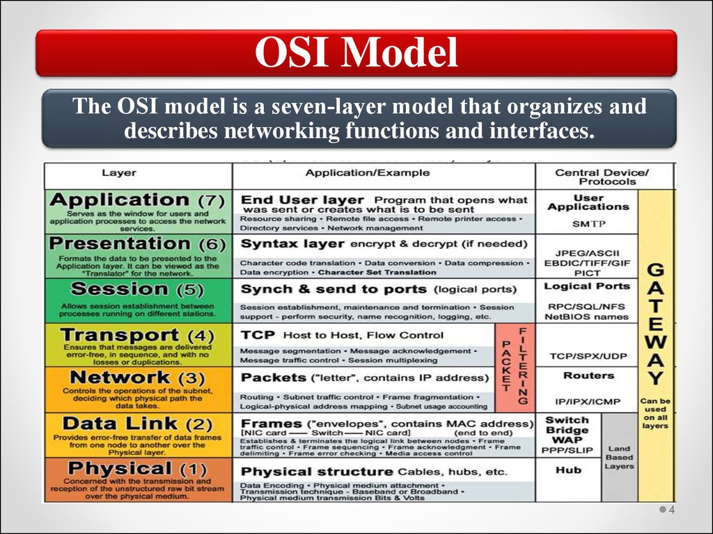
4.
OSI ModelThe OSI model is a seven‐layer model that organizes and
describes networking functions and interfaces.
4
5.
Communication between LayersMoving from the top,
down - messages get
larger and larger. A
message is passed
down, and the lower
layer adds a header
to it. This is called
encapsulation,
because it is like
placing an object
into a capsule. The
header is sometimes
called a wrapper.
Each successive
lower layer
encapsulates what it
receives from the
layer above it.
5
6.
Communication between LayersMoving from the
bottom, up messages get smaller
and smaller. A
message is first
stripped of it's
header, and then the
inner contents (the
"data" portion) is
passed up. This is
"decapsulation“.
Each successive
upper layer receives
the data message
from the layer below,
and then strips off
it's own header and
passes the data up.
6
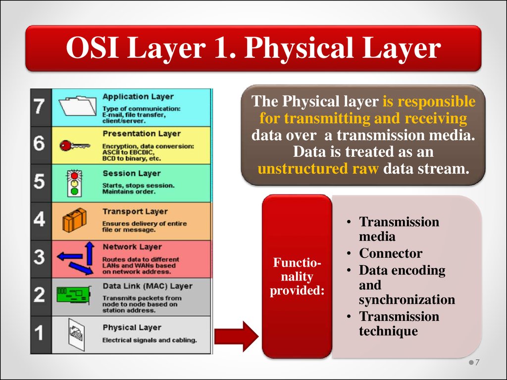
7.
OSI Layer 1. Physical LayerThe Physical layer is responsible
for transmitting and receiving
data over a transmission media.
Data is treated as an
unstructured raw data stream.
Functionality
provided:
• Transmission
media
• Connector
• Data encoding
and
synchronization
• Transmission
technique
7
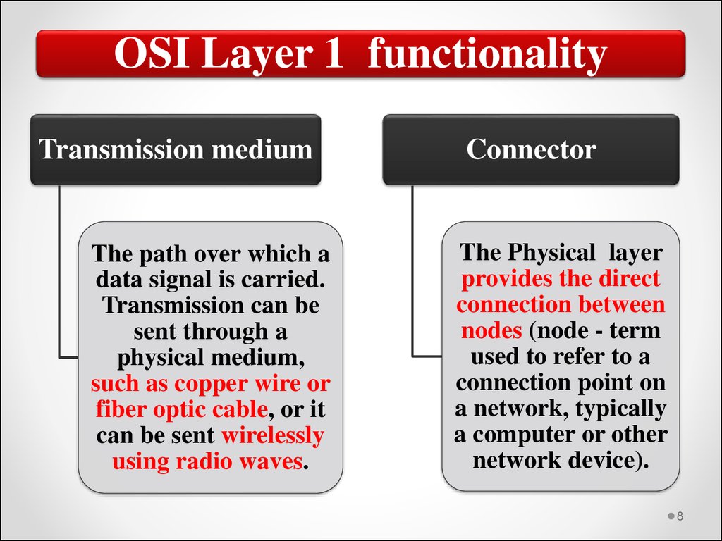
8.
OSI Layer 1 functionalityTransmission medium
The path over which a
data signal is carried.
Transmission can be
sent through a
physical medium,
such as copper wire or
fiber optic cable, or it
can be sent wirelessly
using radio waves.
Connector
The Physical layer
provides the direct
connection between
nodes (node - term
used to refer to a
connection point on
a network, typically
a computer or other
network device).
8
9.
OSI Layer 1 functionalityData encoding
Data conversion of a data
stream to a different
format. In the context of
the Physical layer, it refers
to converting data into a
transmission format. Data
encoding includes
specifying how a 1 or 0 bit
is identified, how to tell the
start and end of a frame,
and how data is
synchronized.
Transmission
technique
Physical layer
specifications also
determine the
transmission
technique. Data can
be sent using either a
digital or analog
transmission. Fiber
optic transmissions,
for example, are
digital transmissions.
9
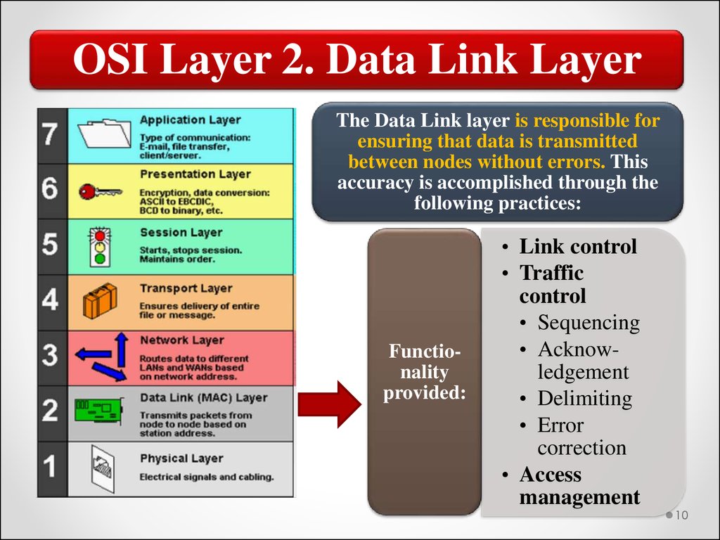
10.
OSI Layer 2. Data Link LayerThe Data Link layer is responsible for
ensuring that data is transmitted
between nodes without errors. This
accuracy is accomplished through the
following practices:
Functionality
provided:
• Link control
• Traffic
control
• Sequencing
• Acknowledgement
• Delimiting
• Error
correction
• Access
management
10
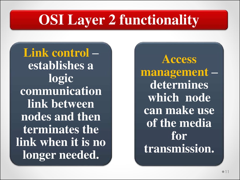
11.
OSI Layer 2 functionalityLink control –
establishes a
logic
communication
link between
nodes and then
terminates the
link when it is no
longer needed.
Access
management –
determines
which node
can make use
of the media
for
transmission.
11
12.
OSI Layer 2 functionalityTraffic control
– manages
frame
transmission
and disables
node
transmission
when no data
is available to
send.
• Sequencing – ensures that frames
are sent (and received)
sequentially.
• Acknowledgement –
acknowledges received frames as
a way of detecting lost or
corrupted frames.
• Delimiting – formats frame start
and end and recognizes these
boundaries on received frames.
• Error correction – verifies
frame integrity.
12
13.
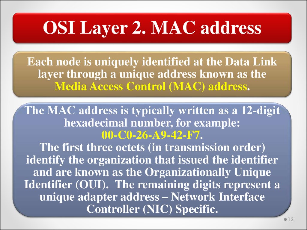
OSI Layer 2. MAC addressEach node is uniquely identified at the Data Link
layer through a unique address known as the
Media Access Control (MAC) address.
The MAC address is typically written as a 12‐digit
hexadecimal number, for example:
00-C0-26-A9-42-F7.
The first three octets (in transmission order)
identify the organization that issued the identifier
and are known as the Organizationally Unique
Identifier (OUI). The remaining digits represent a
unique adapter address – Network Interface
Controller (NIC) Specific.
13
14.
OSI Layer 2. MAC Address14
15.
MAC AddressYou can retrieve the MAC address for an Ethernet network
adapter in a Windows computer by running the IPCONFIG
command. The MAC address is listed with the Ethernet adapter
configuration. It is listed as the adapter’s physical address. In this
case, the address is: 00‐1F‐16‐F8‐2E‐19
15
16.
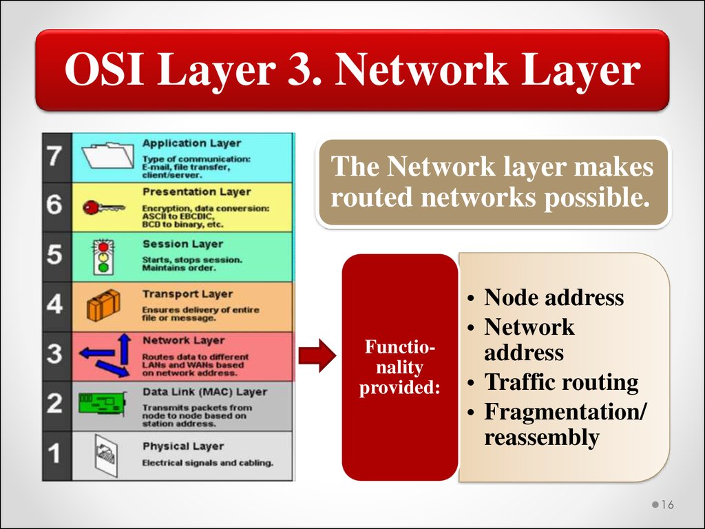
OSI Layer 3. Network LayerThe Network layer makes
routed networks possible.
Functionality
provided:
• Node address
• Network
address
• Traffic routing
• Fragmentation/
reassembly
16
17.
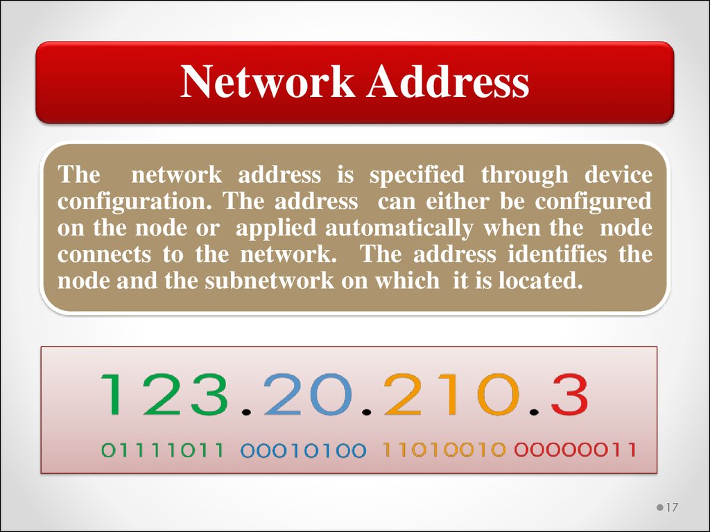
Network AddressThe network address is specified through device
configuration. The address can either be configured
on the node or applied automatically when the node
connects to the network. The address identifies the
node and the subnetwork on which it is located.
17
18.
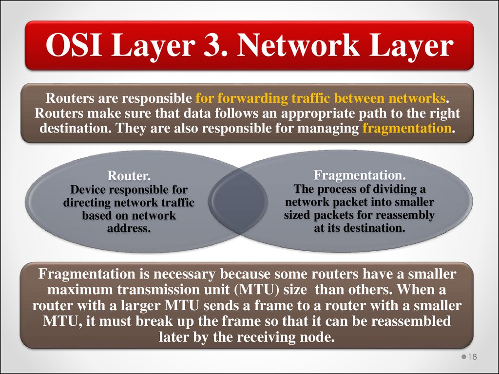
OSI Layer 3. Network LayerRouters are responsible for forwarding traffic between networks.
Routers make sure that data follows an appropriate path to the right
destination. They are also responsible for managing fragmentation.
Router.
Fragmentation.
Device responsible for
directing network traffic
based on network
address.
The process of dividing a
network packet into smaller
sized packets for reassembly
at its destination.
Fragmentation is necessary because some routers have a smaller
maximum transmission unit (MTU) size than others. When a
router with a larger MTU sends a frame to a router with a smaller
MTU, it must break up the frame so that it can be reassembled
later by the receiving node.
18
19.
OSI Layer 4. Transport LayerThe Transport layer is responsible
for error‐free delivery message.
Retransmission of data to recover
errors or lost data will occur in
software managing this layer. The
basic functions are similar to
those provided for frames by the
Data Link layer, but at a higher
level.
Functionality
provided:
Segmentation
Acknowledgement
Traffic control
Multiplexing
19
20.
Transport LayerSegmentation
• Splits the message (if necessary) for
reassembly by the receiving Transport layer.
Acknowledgement
• Uses acknowledgements to provide reliable
delivery.
Traffic control
• Enables transmission only when a message
is available.
Multiplexing
• Manages transmission of multiple messages.
The Transport layer adds header information that enables
the receiving host to reassemble the message. This includes
sequence numbering, if it is not provided in the lower layers.
20
21.
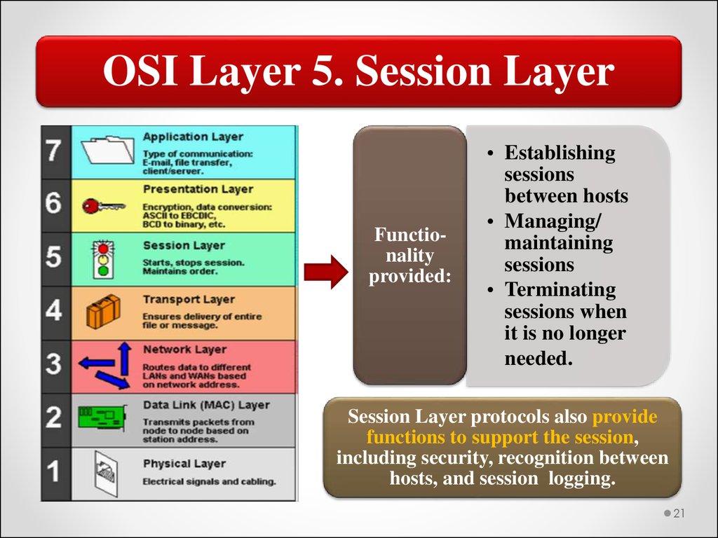
OSI Layer 5. Session LayerFunctionality
provided:
• Establishing
sessions
between hosts
• Managing/
maintaining
sessions
• Terminating
sessions when
it is no longer
needed.
Session Layer protocols also provide
functions to support the session,
including security, recognition between
hosts, and session logging.
21
22.
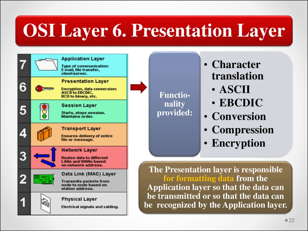
OSI Layer 6. Presentation LayerFunctionality
provided:
• Character
translation
• ASCII
• EBCDIC
• Conversion
• Compression
• Encryption
The Presentation layer is responsible
for formatting data from the
Application layer so that the data can
be transmitted or so that the data can
be recognized by the Application layer.
22
23.
Presentation LayerCharacter
translation
typically
ASCII or
EBCDIC.
Conversion
as necessary,
including bit
order,
formatting end
of line, and so
forth.
Compression
applying data
compression
algorithms to
reduce the size of
data being
transmitted.
Encryption
encrypting/
decrypting
data to
provide
data
security.
American Standard Code
for Information
Interchange (ASCII)
• Character encoding method that is used to represent
128 characters as 7-bit values. Most commonly used
by the UNIX operating system and some legacy
applications such as DOS-based applications.
Extended Binary Coded
Decimal Interchange Code
(EBCDIC)
• Binary code for encoding characters developed by
IBM and primarily used in mainframe computers.
23
24.
OSI Layer 7. Application LayerFunctionality
provided:
• Remote file and
printer access
• Resource sharing
• Communications
between processes
• Electronic messaging
and e-mail
• Directory services
• Virtual devices and
virtual
communications
• Web browsing
Users and applications are provided
access to network services through the
Application layer.
24
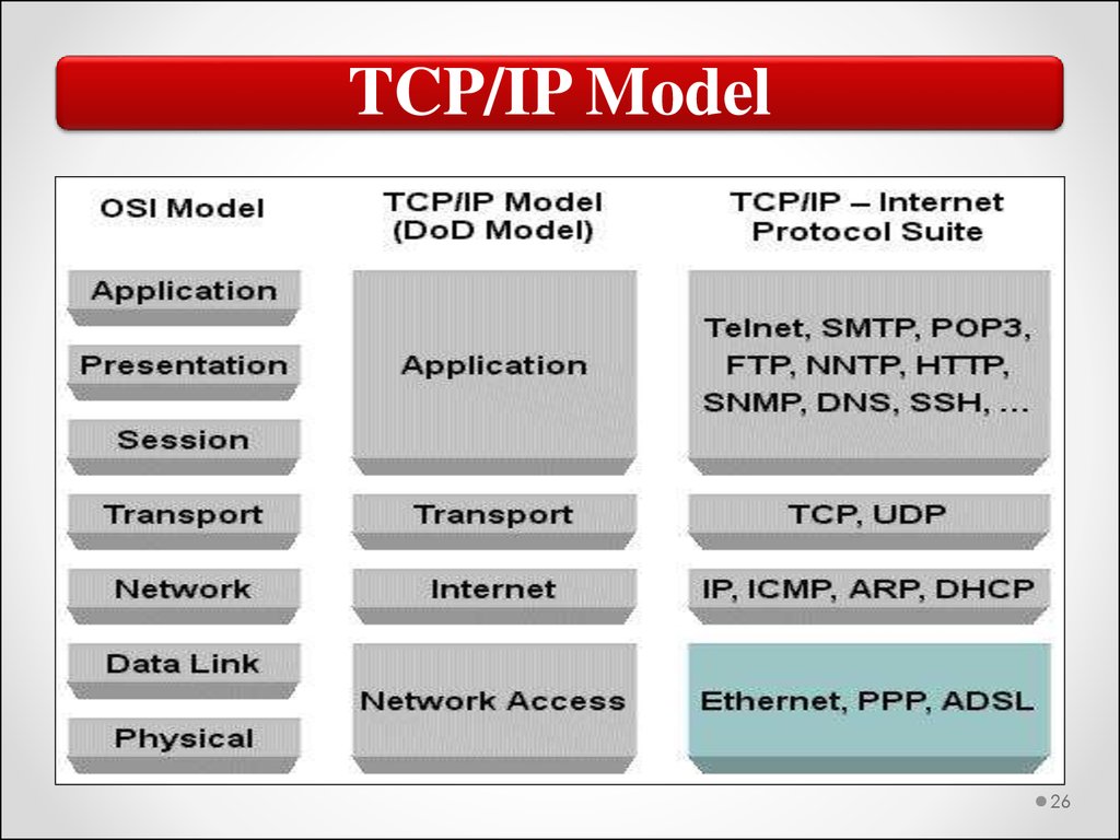
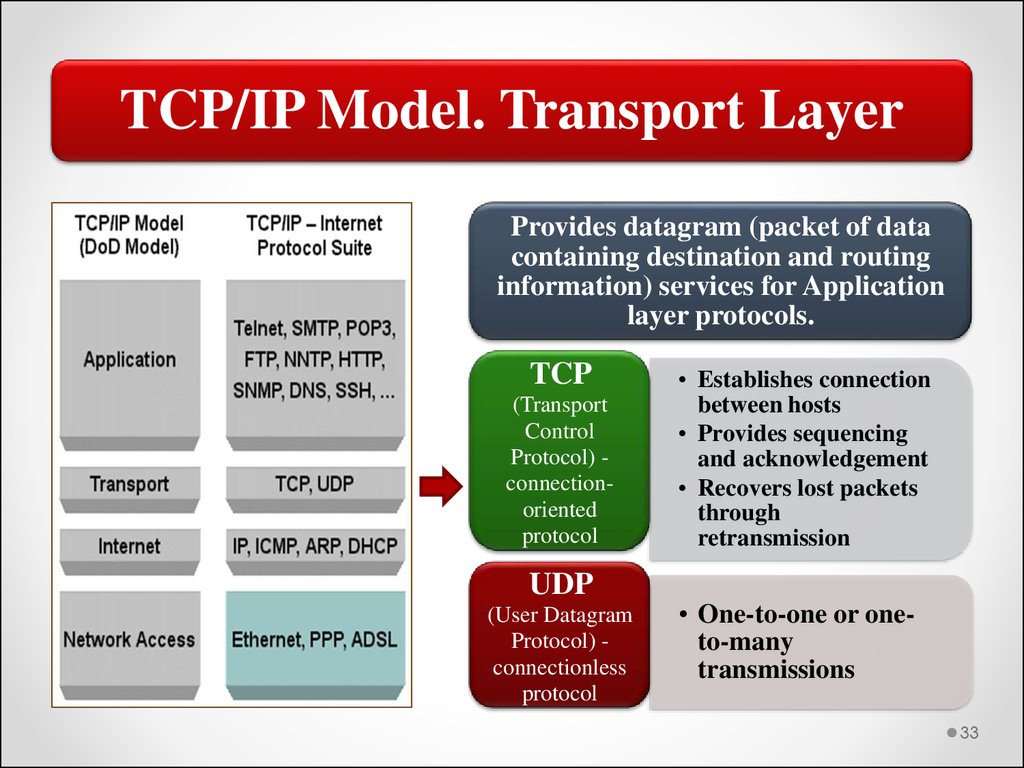
25.
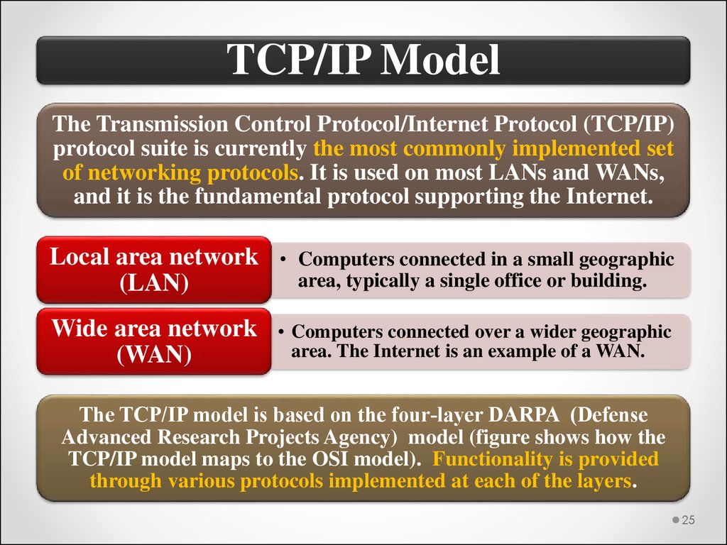
TCP/IP ModelThe Transmission Control Protocol/Internet Protocol (TCP/IP)
protocol suite is currently the most commonly implemented set
of networking protocols. It is used on most LANs and WANs,
and it is the fundamental protocol supporting the Internet.
Local area network • Computers connected in a small geographic
area, typically a single office or building.
(LAN)
Wide area network
(WAN)
• Computers connected over a wider geographic
area. The Internet is an example of a WAN.
The TCP/IP model is based on the four‐layer DARPA (Defense
Advanced Research Projects Agency) model (figure shows how the
TCP/IP model maps to the OSI model). Functionality is provided
through various protocols implemented at each of the layers.
25
26.
TCP/IP Model26
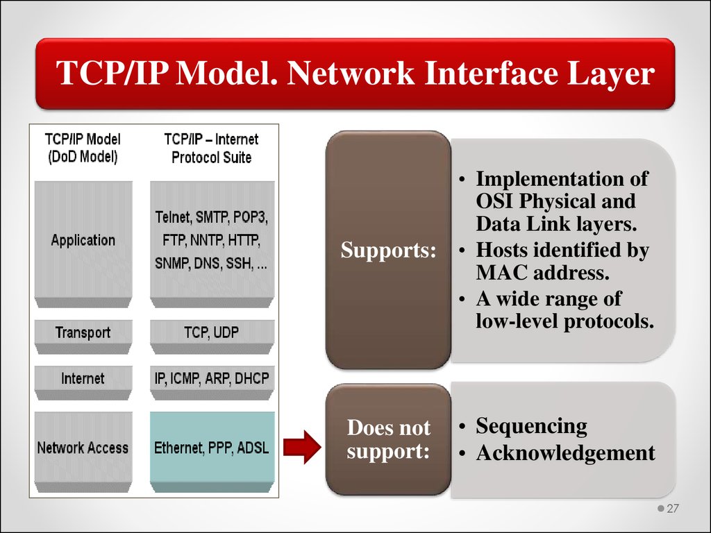
27.
TCP/IP Model. Network Interface Layer• Implementation of
OSI Physical and
Data Link layers.
Supports: • Hosts identified by
MAC address.
• A wide range of
low-level protocols.
Does not
support:
• Sequencing
• Acknowledgement
27
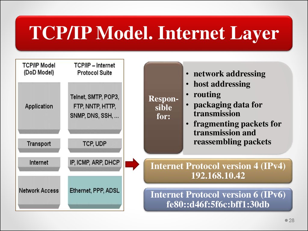
28.
TCP/IP Model. Internet LayerRespon
sible
for:
network addressing
host addressing
routing
packaging data for
transmission
fragmenting packets for
transmission and
reassembling packets
Internet Protocol version 4 (IPv4)
192.168.10.42
Internet Protocol version 6 (IPv6)
fe80::d46f:5f6c:bff1:30db
28
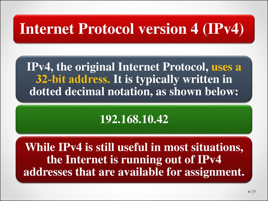
29.
Internet Protocol version 4 (IPv4)IPv4, the original Internet Protocol, uses a
32‐bit address. It is typically written in
dotted decimal notation, as shown below:
192.168.10.42
While IPv4 is still useful in most situations,
the Internet is running out of IPv4
addresses that are available for assignment.
29
30.
Internet Protocol version 6 (IPv6)IPv6 was developed to extend the address space by
providing a 128‐bit address, represented as a series
of hexadecimal numbers:
fe80::d46f:5f6c:bff1:30db
The goal for TCP/IP implementations, including the
Internet, is to gradually switch from IPv4 to IPv6. Most
network devices now support both IPv4 and IPv6
addresses. Computer operating systems configure hosts
with both IPv4 and IPv6 addresses. However, IPv6
addresses are largely ignored because they are not
currently required in most network environments.
30
31.
Address Resolution Protocol (ARP)One protocol implemented in the Internet layer that deserves
special mention is ARP. There are versions of ARP in both IPv4
and IPv6. In each case, its basic function is to map IP addresses to
MAC addresses.
Address Resolution • TCP/IP protocol designed to provide
IP address/MAC address resolution.
Protocol (ARP)
MAC address information is collected through the use of broadcast
transmissions. To reduce the number of broadcasts, each host
maintains its own ARP cache. You can enter address information
into the cache as static entries, but most of the information is
maintained dynamically as the result of ARP broadcasts.
Broadcast
• One-to-many connectionless
communication.
31
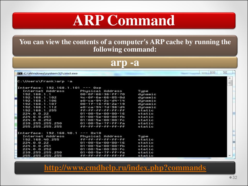
32.
ARP CommandYou can view the contents of a computerʹs ARP cache by running the
following command:
arp -a
http://www.cmdhelp.ru/index.php?commands
32
33.
TCP/IP Model. Transport LayerProvides datagram (packet of data
containing destination and routing
information) services for Application
layer protocols.
TCP
(Transport
Control
Protocol) connectionoriented
protocol
UDP
(User Datagram
Protocol) connectionless
protocol
• Establishes connection
between hosts
• Provides sequencing
and acknowledgement
• Recovers lost packets
through
retransmission
• One-to-one or oneto-many
transmissions
33
34.
TCP and UDP protocolsTCP is a connection‐oriented protocol. In other words, it provides
a reliable, one‐to‐one connection between two network hosts. TCP
is used whenever it is necessary to ensure delivery of data.
TCP is
responsible for:
• Establishing the connection between hosts
• Sequencing and acknowledging packets sent
between hosts
• Recovering lost packets (through retransmission)
UDP is a connectionless protocol. It can be used for one‐to‐one or
one‐to many (broadcast) transmissions. Because UDP is
connectionless, it does not ensure reliable delivery, although reliable
communication can be implemented through higher‐level protocols
that use UDP for delivery. Typically, UDP is used when very little
data (no more than one packet) is being sent.
34
35.
TCP/IP Model. Application LayerInformation exchange protocols. It is
the interface between a computer’s
users and applications and the network
services provided by TCP/IP.
Management
protocols
• Managing and
resolving host
names with IP
addresses
• Maintaining and
sharing route
information
between routers
• Automatically
providing network
configuration
information for host
computers
35
36.
EthernetEthernet is a low‐level communication protocol
that is implemented at the Physical and Data
Link layers of the OSI model or the Network
Interface layer of the TCP/IP model.
Standard
defines:
• Transmission media and connector types
• Cable segment lengths
• Transmission signals (strength and
format)
• Frame format
• Network access method
36
37.
EthernetEthernet is currently the most commonly used communication
standard for LAN technologies. One reason for this is that
Ethernet, in its current form, is a standardized technology based
on the IEEE 802.3 standard.
Ethernet was originally introduced as a proprietary
communication system. It was first developed by Xerox. By 1980,
Ethernet was the clear winner, and today, other low‐level
protocols are rarely seen except in very specialized applications,
such as some manufacturing process control systems.
Ethernet has become so common that most manufacturers build
an Ethernet network adapter (or NIC) directly into a computer’s
motherboard for both desktop and laptop (and some tablet)
computers.
37
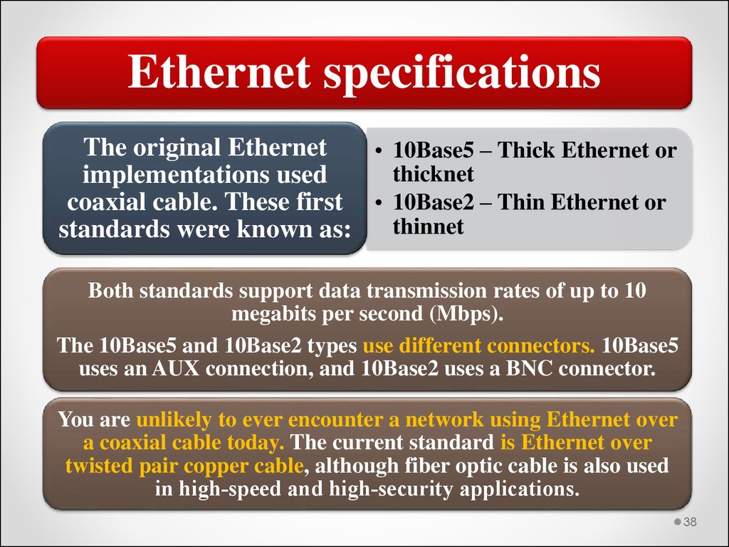
38.
Ethernet specificationsThe original Ethernet
• 10Base5 – Thick Ethernet or
thicknet
implementations used
coaxial cable. These first • 10Base2 – Thin Ethernet or
thinnet
standards were known as:
Both standards support data transmission rates of up to 10
megabits per second (Mbps).
The 10Base5 and 10Base2 types use different connectors. 10Base5
uses an AUX connection, and 10Base2 uses a BNC connector.
You are unlikely to ever encounter a network using Ethernet over
a coaxial cable today. The current standard is Ethernet over
twisted pair copper cable, although fiber optic cable is also used
in high‐speed and high‐security applications.
38
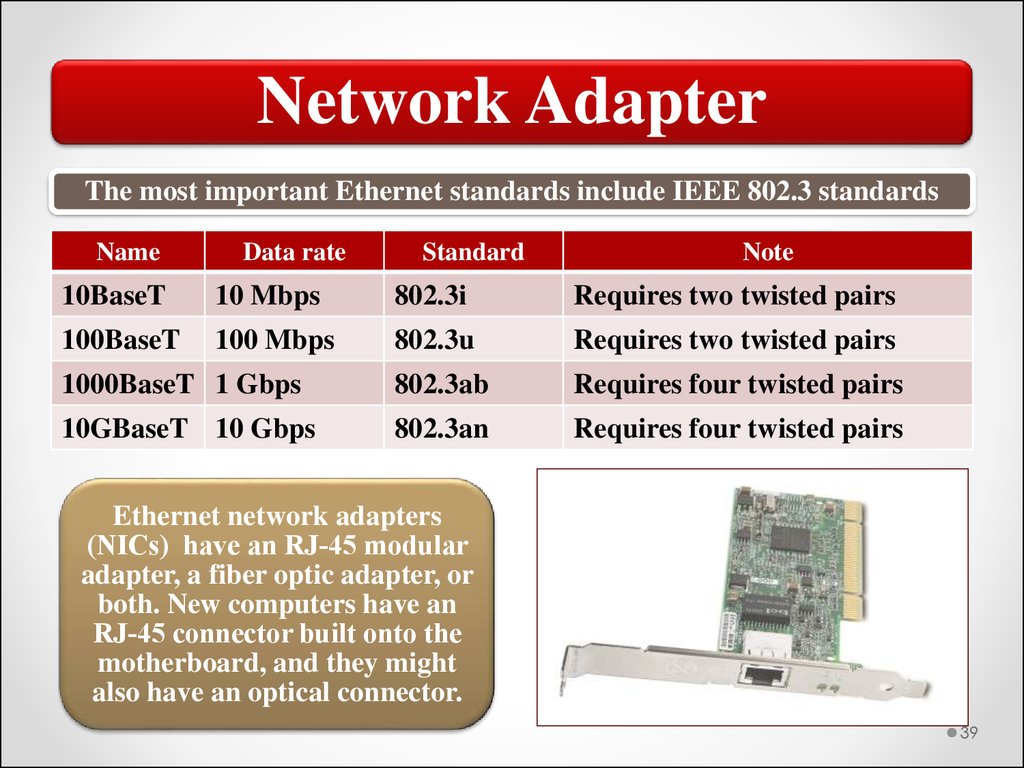
39.
Network AdapterThe most important Ethernet standards include IEEE 802.3 standards
Name
Data rate
Standard
Note
10BaseT
10 Mbps
802.3i
Requires two twisted pairs
100BaseT
100 Mbps
802.3u
Requires two twisted pairs
1000BaseT 1 Gbps
802.3ab
Requires four twisted pairs
10GBaseT 10 Gbps
802.3an
Requires four twisted pairs
Ethernet network adapters
(NICs) have an RJ‐45 modular
adapter, a fiber optic adapter, or
both. New computers have an
RJ‐45 connector built onto the
motherboard, and they might
also have an optical connector.
39
40.
Ethernet Traffic TypesUnicast - a transmission sent to one specific host
identified by a specific address.
Broadcast - a transmission sent to all hosts on a
network or network segment without regard for a
host address.
Multicast - a transmission sent to an identified
group of hosts addressed as a multicast group,
which is effectively a distribution group.
Anycast - a transmission sent to the first host within
a distribution group rather than all members of the
group.
40
41.
Unicast and Broadcast trafficsTypically, most of the traffic on a network will be
unicast traffic, one‐to-one communication
between hosts. In a switched network, traffic is
filtered and forwarded at the switch.
Broadcast traffic is usually related to network
management activities. All hosts can potentially
receive and will, in turn, process the traffic. ARP,
for example, uses broadcasts to resolve MAC
addresses.
41
42.
Multicast and Anycast trafficsMulticast traffic is similar to broadcast traffic in that it
is one‐to‐many communications. The difference between
the two is that in multicast traffic, the data is targeted at
specific hosts. The advantage multicast traffic has over
unicast traffic is that it can reach multiple destinations
with a single transmission.
Anycast traffic is also sent to a distribution group, which
is a set of hosts that have the same anycast destination
address. However, the traffic is processed by the first host
receiving the transmission. Anycast is most often used in
managing route information and router availability.
42
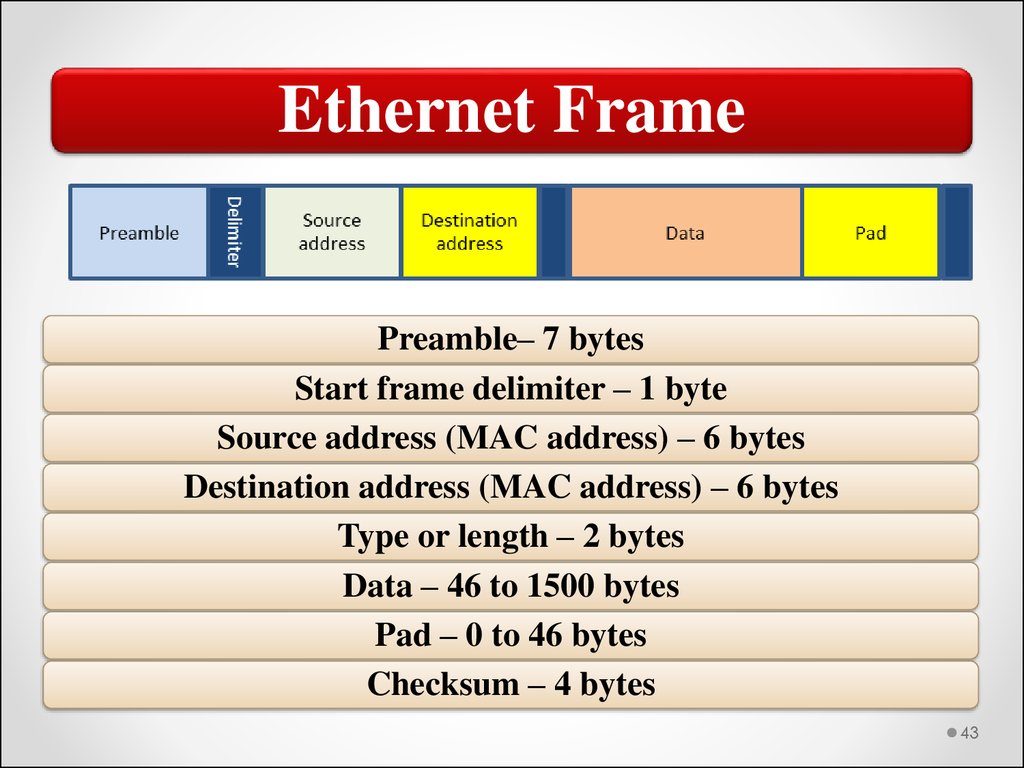
43.
Ethernet FramePreamble– 7 bytes
Start frame delimiter – 1 byte
Source address (MAC address) – 6 bytes
Destination address (MAC address) – 6 bytes
Type or length – 2 bytes
Data – 46 to 1500 bytes
Pad – 0 to 46 bytes
Checksum – 4 bytes
43
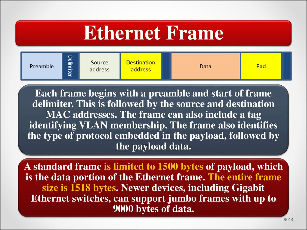
44.
Ethernet FrameEach frame begins with a preamble and start of frame
delimiter. This is followed by the source and destination
MAC addresses. The frame can also include a tag
identifying VLAN membership. The frame also identifies
the type of protocol embedded in the payload, followed by
the payload data.
A standard frame is limited to 1500 bytes of payload, which
is the data portion of the Ethernet frame. The entire frame
size is 1518 bytes. Newer devices, including Gigabit
Ethernet switches, can support jumbo frames with up to
9000 bytes of data.
44
45.
CSMA/CDShared media Ethernet uses a network access method known as
CSMA/CD. With CSMA/CD, a host will first check to see if it can
detect another host transmitting. If it cannot, it will transmit its
frame. This was an issue in older Ethernet networks that shared a
coaxial cable connection or connected through a hub.
Carrier Sense Multiple • Network access method used by the Ethernet
protocol, supporting shared access to the
Access with Collision
transmission media.
Detection (CSMA/CD)
The problem CSMA/CD is that you might have more than one host
trying to transmit at the same time. This is known as a collision and
results in the corruption of all frames transmitted at that time.
45
46.
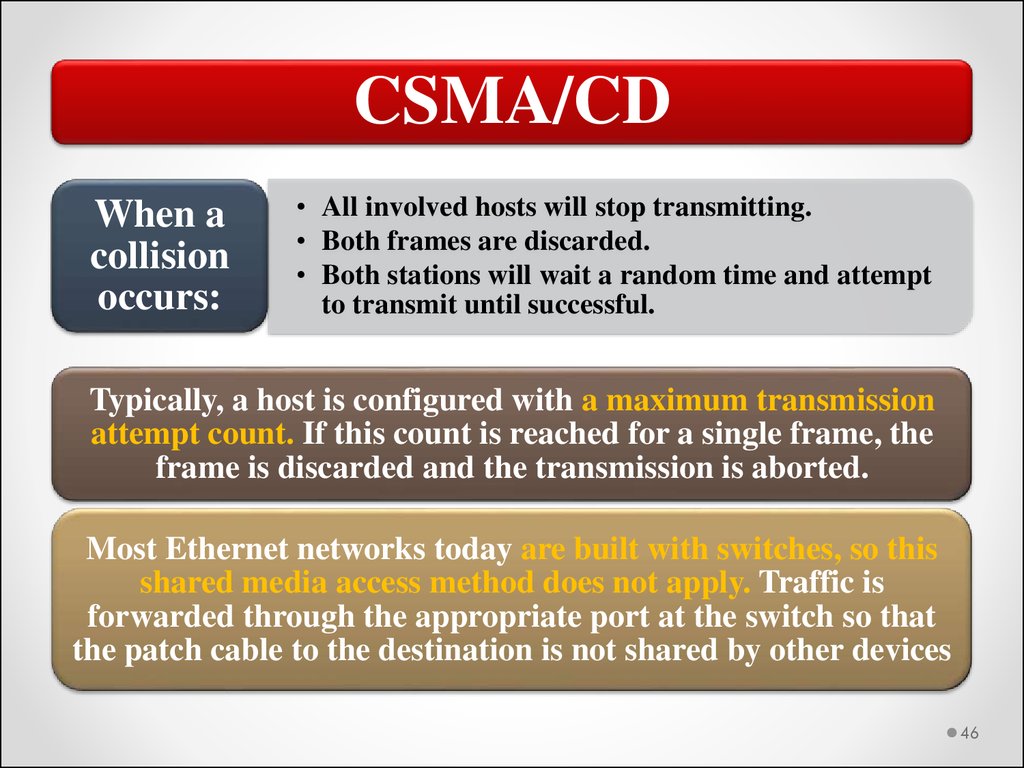
CSMA/CDWhen a
collision
occurs:
• All involved hosts will stop transmitting.
• Both frames are discarded.
• Both stations will wait a random time and attempt
to transmit until successful.
Typically, a host is configured with a maximum transmission
attempt count. If this count is reached for a single frame, the
frame is discarded and the transmission is aborted.
Most Ethernet networks today are built with switches, so this
shared media access method does not apply. Traffic is
forwarded through the appropriate port at the switch so that
the patch cable to the destination is not shared by other devices
46
47.
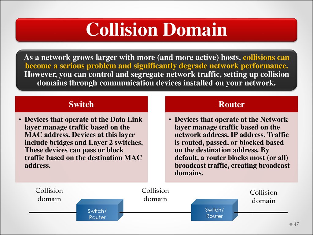
Collision DomainAs a network grows larger with more (and more active) hosts, collisions can
become a serious problem and significantly degrade network performance.
However, you can control and segregate network traffic, setting up collision
domains through communication devices installed on your network.
Switch
Router
• Devices that operate at the Data Link
layer manage traffic based on the
MAC address. Devices at this layer
include bridges and Layer 2 switches.
These devices can pass or block
traffic based on the destination MAC
address.
Collision
domain
• Devices that operate at the Network
layer manage traffic based on the
network address. IP address. Traffic
is routed, passed, or blocked based
on the destination address. By
default, a router blocks most (or all)
broadcast traffic, creating broadcast
domains.
Collision
domain
Switch/
Router
Collision
domain
Switch/
Router
47
48.
VLANIn the early days of networking, network hosts
could be organized by physical location only.
Older network designs used bridges and
routers to establish boundaries between hosts.
Modern switches provide segmentation
through VLANs. A VLAN looks like a routed
subnet, also referred to as a Layer 3
subnetwork, to the rest of the network. Each
VLAN has its own network IP address for
routing purposes.
48
49.
VLANThe simplest type of VLAN is a static VLAN. In this configuration, switch
ports are assigned to VLANs, creating the equivalent of Layer 3
subnetworks. When a device is connected to a port, it becomes part of the
VLAN to which the port is assigned.
A VLAN can also be created and managed dynamically. You can assign
ports to a VLAN based on factors such as a connected computer’s MAC
address or the username used when logging onto the computer.
Static VLAN - are also
known as Port-based
VLANs are created by
allocating ports to a VLAN
manually.
Dynamic VLAN – are
made by allocating the
host to a VLAN when
host is plugged in a
switch by the use of
hardware addresses
from database.
49
50.
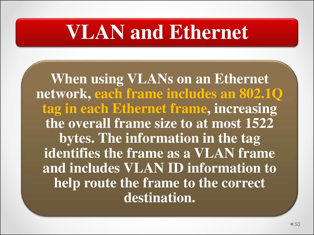
VLAN and EthernetWhen using VLANs on an Ethernet
network, each frame includes an 802.1Q
tag in each Ethernet frame, increasing
the overall frame size to at most 1522
bytes. The information in the tag
identifies the frame as a VLAN frame
and includes VLAN ID information to
help route the frame to the correct
destination.
50
51.
Wireless NetworkingDefined by 802.11 standards. Standards in the 802.11 family
define a through-the-air interface between a wireless client
and a base station access point (AP) or between two or more
wireless clients.
Wireless adapters (NIC) include radio frequency
transmitter and receiver operating in a specific frequency
range, depending on the standard or standards that the
wireless NIC supports.
Access points (APs) provide a common connection point for
devices. Most 802.11 wireless network configurations are
based around one or more access points (APs). The AP acts
as a central point of access for wireless hosts.
51
52.
Current Wireless StandardsStandard
802.11a
802.11b
Frequency
5 GHz
2.4 GHz
Maximum data rate
54 Mbps
11 Mbps
802.11g
802.11n
2.4 GHz
2.4/5 GHz
54 Mbps
Up to 600Mbps
802.11g is downward compatible with 802.11b
802.11n is downward compatible with 802.11a, 802.11b,
and 802.11g
52
53.
CSMA/CAThe network access method used by 802.11 wireless is
CSMA/CA (Carrier Sense Multiple Access with
Collision Avoidance) similar to CSMA/CD. Sending
host cannot receive and cannot detect collisions.
With CSMA/CA, a host listens for a predetermined
amount of time to ensure the availability of the channel
it is going to use for transmission.
A request to send (RTS) signal is sent, informing the
other hosts of its intent to transmit.
The sending host waits for a clear-to‐send (CTS) signal
before starting transmission.
53
54.
Security BasicsAuthentication and resource
access
Data and communication
security
54
55.
Authentication FormsIf you have ever logged onto a computer, when connecting to
a network, running management utilities, or attempting to
access resources, such as files, you have taken part in an
authentication process. For users, authentication is usually
based on one or more of the following:
What you know •Password or PIN
What you have •Smart card, ID badge, etc.
Who you are
•Biometric information
55
56.
Data SecurityPrevent data from being exposed
Prevent data from being corrupted
The use of data encryption plays a central role in security in
most network systems. Data is stored in an encrypted form on
the disk. Even if an unauthorized user (or program) gains
access to a file’s storage location, the file is still protected
through its encryption.
Encryption - the process of using an algorithm to render
the data unreadable without the technology and knowledge
necessary to reverse the process.
56
57.
SummaryThe OSI
model
describes
network
functions
as seven
distinct
layers.
• Layer 1, the Physical layer, is responsible for data
transmission at the transmission media level.
• Layer 2, the Data Link layer, is responsible for lowlevel link control and traffic control.
• Layer 3, the Network layer, is responsible for network
addressing and routing traffic through a network.
• Layer 4, the Transport layer, is responsible for
ensuring error-free message delivery.
• Layer 5, the Session layer, establishes and manages
communication sessions between hosts.
• Layer 6, the Presentation layer, is responsible for data
translation and formatting.
• Layer 7, the Application layer, provides users and
applications with access to networking functionality
and network services.
57
58.
Summary (cont’d)The MAC address is implemented at Layer 2 and uniquely identifies a
network host.
The TCP/IP Network Interface layer implements functionality from the
OSI model Physical and Data Link layers.
The TCP/IP Internet layer implements functionality from the OSI model
Network layer (IPv4 and IPv6 are implemented at the Internet layer).
The TCP/IP Transport layer implements functionality from the OSI
model Transport and Session layers.
The TCP/IP Application layer implements functionality from the OSI
model Session, Presentation, and Application layers.
802.3 Ethernet and 802.11 Wi-Fi are implemented at the OSI model
Physical and Data Link layers.
58
59.
Summary (cont’d)Network traffic can be a mix of unicast, broadcast, multicast, and
anycast traffic.
802.3 uses CSMA/CD for network access.
802.11 uses CSMA/CA for network access.
Authentication factors include what you know, what you have, and
who you are.
Data security helps to prevent data from being improperly
disclosed or corrupted.
VLANs provide a way to segment network devices based on port
connection or other characteristics rather than physical location.
59
60.
Thank you foryour attention!
60