


 Промышленность
Похожие презентации:


MAN Diesel PrimeServ Academy Hydraulic Power Supply, HPS
1. MAN Diesel PrimeServ Academy Hydraulic Power Supply, HPS
MEMEEngine
Enginecontrol
controlsystem
system--Hydraulic
HydraulicPower
PowerSupply
Supply(July
(July2009)
2009)
© MAN Diesel
2009/07/01
<1>
2.
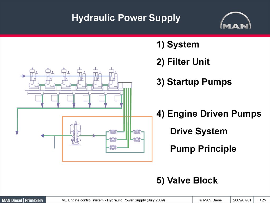
Hydraulic Power Supply1) System
2) Filter Unit
3) Startup Pumps
4) Engine Driven Pumps
Drive System
Pump Principle
5) Valve Block
ME Engine control system - Hydraulic Power Supply (July 2009)
© MAN Diesel
2009/07/01
<2>
3. Lubricating and Cooling Oil System
50 μ filterConnection to
hydraulic system
ME Engine control system - Hydraulic Power Supply (July 2009)
© MAN Diesel
2009/07/01
<3>
4. Hydraulic Power Supply - HPS
Contamination ofhydraulic oil must
not exceed:
ISO 4406: 16/13
or
Bearings and piston cooling
NAS Code: 7
In 100 ml oil sample the
number of particles with
the size should be within
the range.
16: 32,000 ≤ 6μm ≤ 64,000
13: 4,000 ≤ 14 μm ≤ 8,000
25 μ
6μ
Supply line from cooler and 50 μ filter
ME Engine control system - Hydraulic Power Supply (July 2009)
© MAN Diesel
2009/07/01
<4>
5. Separate Hydraulic System
ME Engine control system - Hydraulic Power Supply (July 2009)© MAN Diesel
2009/07/01
<5>
6. Separate Hydraulic System
ME Engine control system - Hydraulic Power Supply (July 2009)© MAN Diesel
2009/07/01
<6>
7. Filter Unit, Schematic
Old plants = 10 µmNew plants = 6 µm
25 µ
ME Engine control system - Hydraulic Power Supply (July 2009)
© MAN Diesel
2009/07/01
<7>
8. HPS Components Filter and pumps
Auto FilterBackup Filter
Mechanically driven
Hydraulic pumps
Electrically driven
Hydraulic start-up
pumps
8
ME Engine control system - Hydraulic Power Supply (July 2009)
© MAN Diesel
2009/07/01
9. HPS Components Filter and pumps
Filter unitStart-up pumps
High pressure
pumps
Drain pipe
System oil
High pressure pipes
9
ME Engine control system - Hydraulic Power Supply (July 2009)
© MAN Diesel
2009/07/01
10. Filter
Single filter cartridgeME Engine control system - Hydraulic Power Supply (July 2009)
© MAN Diesel
2009/07/01
< 10 >
11. Filter Cartridges
10 µm filter cartridge:6 µm filter cartridge:
08/06 = production month/year
09/06 = production month/year
1340006 = filter cartridge ID
1341446 = filter cartridge ID
25 = manufacturer's filter mesh code
Sintered filter material
ME Engine control system - Hydraulic Power Supply (July 2009)
© MAN Diesel
2009/07/01
< 11 >
12. Automatic Filter
Filtering processME Engine control system - Hydraulic Power Supply (July 2009)
Back flushing process
© MAN Diesel
2009/07/01
< 12 >
13. Automatic Filter, Type 6.64
ME Engine control system - Hydraulic Power Supply (July 2009)© MAN Diesel
2009/07/01
< 13 >
14. Backflushing Line to Lube Oil Tank
ME Engine control system - Hydraulic Power Supply (July 2009)© MAN Diesel
2009/07/01
< 14 >
15. Start up Pumps, fixed
Safety valve settingAutomatic mode:
175 bar
Stopped at Finish With Engine.
Master pump running at engine standby.
(both pumps are running during pressure
build up).
Stopped via a timer at a specified engine
RPM (default 15 % MCR)
Manual mode:
Controlled by the operator via the Main
Operating Panel
ME Engine control system - Hydraulic Power Supply (July 2009)
© MAN Diesel
2009/07/01
< 15 >
16.
HPS Components,Start-up Pumps
Drain
Drain
Electric
motor
Outlet
Outlet
Inlet
Drain
Pump
Pump drain
Pressure relief valve,
setpoint 175 bar
ME Engine control system - Hydraulic Power Supply (July 2009)
© MAN Diesel
2009/07/01
16
17.
HPS Components,Start-up Pumps
Inlet
Electric motor
Pressure relief
valve set point
175 / 225 bar
Pump
Outlet
Valve
Pump drain
ME Engine control system - Hydraulic Power Supply (July 2009)
© MAN Diesel
2009/07/01
17
18. Electrically Driven Start-up Pumps
ME Engine control system - Hydraulic Power Supply (July 2009)© MAN Diesel
2009/07/01
< 18 >
19. Engine Driven Pumps
ME Engine control system - Hydraulic Power Supply (July 2009)© MAN Diesel
2009/07/01
< 19 >
20. Axial Piston Pump – Bosch Rexroth
Axial Piston Pump – A4VSO xxx HS3xxx…. (Bosch-Rexroth)ME Engine control system - Hydraulic Power Supply (July 2009)
© MAN Diesel
2009/07/01
< 20 >
21. Axial Piston Pump – Rotating Parts
PistonsPressure side
Suction side
ME Engine control system - Hydraulic Power Supply (July 2009)
© MAN Diesel
2009/07/01
< 21 >
22. Swash Plate Principle
AheadME Engine control system - Hydraulic Power Supply (July 2009)
Astern
© MAN Diesel
2009/07/01
< 22 >
23. Axial Piston Pump
Pump sizes:• 125 ccm/rev - 3 pumps
• 180 ccm/rev - 3 pumps
• 250 ccm/rev - 3 pumps
• 355 ccm/rev - 3 pumps
• 500 ccm/rev - 3 to 5 pumps
ME Engine control system - Hydraulic Power Supply (July 2009)
© MAN Diesel
2009/07/01
< 23 >
24.
Design features forK+S80ME-C9, K98ME-C7
210 Bar 300 Bar
Working pressure increased from 210 bar to 300 bar resulting in:
HPS:
Necessary pump size reduced from 355 cc to 250 cc.
Only 3 pumps needed.
Same pipe and hose dimensions.
This is because of the relation between Q’ (flow) and pressure (p) shown by the
equation:
P=Q’x p, where P is the power generated by the pump, the power consumption is
the same; therefore a higher pressure will result in a lower flow
ME Engine control system - Hydraulic Power Supply (July 2009)
© MAN Diesel
2009/07/01
25. 7S50ME-C Hydraulic Power Supply
AccumulatorSafety and
accumulator block
Three engine driven
axial piston pumps
with flow controlled
by ECS
Generates hydraulic
oil pressure up to
250 bar
Redundancy:
The engine can
operate on two
pumps
Gear Box
ME Engine control system - Hydraulic Power Supply (July 2009)
© MAN Diesel
2009/07/01
26. 7S50ME-C Gear Box for HPS
Output wheel ………………Intermediate wheel……………….
Connections wheel……………
Gearwheel on crankshaft…
Two rows of gears, one is spare.
Spacer………..
Gear ratio - 12:1
ME Engine control system - Hydraulic Power Supply (July 2009)
© MAN Diesel
2009/07/01
< 26 >
27. Pump Drive and Moment Compensator
ME Engine control system - Hydraulic Power Supply (July 2009)© MAN Diesel
2009/07/01
< 27 >
28. Pump Drive
Hydraulic PumpStep Up Gear
Chain wheel for
4” Duplex chain
ME Engine control system - Hydraulic Power Supply (July 2009)
© MAN Diesel
2009/07/01
< 28 >
29. Pump Shaft Principle
Gear endHigh friction disc
Pump end
ME Engine control system - Hydraulic Power Supply (July 2009)
© MAN Diesel
2009/07/01
< 29 >
30. Hydraulic Power Supply 7S60ME-C
ME Engine control system - Hydraulic Power Supply (July 2009)© MAN Diesel
2009/07/01
< 30 >
31.
Access to Hydraulic Power SupplyME Engine control system - Hydraulic Power Supply (July 2009)
© MAN Diesel
2009/07/01
32. Access to Hydraulic Power Supply
Design of Hydraulic Power Supply• Mounting of HPS
• Structure of HPS and Framebox
• Design of components
ME Engine control system - Hydraulic Power Supply (July 2009)
© MAN Diesel
2009/07/01
< 33 >
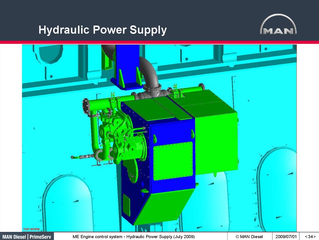
33.
Hydraulic Power SupplyME Engine control system - Hydraulic Power Supply (July 2009)
© MAN Diesel
2009/07/01
< 34 >
34. Hydraulic Power Supply
12K98MEEngine driven Hydraulic Power Supply
ME Engine control system - Hydraulic Power Supply (July 2009)
© MAN Diesel
2009/07/01
35. 12K98ME Engine driven Hydraulic Power Supply
10-12K98ME/ME-C5 x 500 ccm pumps
Fore side
Aft side
ME Engine control system - Hydraulic Power Supply (July 2009)
© MAN Diesel
2009/07/01
< 36 >
36. 10-12K98ME/ME-C
Engine Driven PumpsP2
P1
1204
Sensors for suction pressure.
Low pressure = shut down
ME Engine control system - Hydraulic Power Supply (July 2009)
© MAN Diesel
2009/07/01
< 37 >
37. Engine Driven Pumps
Automatic mode:The pressure set point is depending on the engine load.
The pumps have two running modes, 1 in pressure control mode [Ctrl]
(selected via the MOP screen), 2 in follow mode [Folw].
The [Ctrl] pump is running 50% and compensates immediately for deviations
between actual pressure and set point. Over time the [Folw] pumps will take
over the compensation while the [Ctrl] pump goes back to 50 %.
In case the pressure controlling pump faces a failure, one of the other pumps
will take over pressure control.
Manual mode:
The pressure set point is set by the operator
ME Engine control system - Hydraulic Power Supply (July 2009)
© MAN Diesel
2009/07/01
< 38 >
38. Engine Driven Pumps
- SummaryIn case of control failure of a pump, the swash plate will be forced to
maximum capacity in AHEAD direction.
Pump No. 1 is controlled by ACU 1, pump 2 by ACU 2, and pump 3 by ACU 3.
Pump Nos. 1, 2, and 3 have their own sensor for system pressure,
connected to their controlling ACU
Pump Nos. 4 and 5 are controlled by a binary signal, either max
capacity AHEAD or ASTERN. No. 4 is controlled from ECU A, and No.
5 from ECU B.
All pumps have sensors for suction pressure. If the pressure is to low,
or all sensors are failing, a SHUT DOWN will be activated.
ME Engine control system - Hydraulic Power Supply (July 2009)
© MAN Diesel
2009/07/01
< 39 >
39. Engine Driven Pumps - Summary
Leak DetectionShut down level
Alarm level
ME Engine control system - Hydraulic Power Supply (July 2009)
© MAN Diesel
2009/07/01
< 40 >
40. Leak Detection
Box for hydraulic pumpsDrainpipe
Sensor LS 1235 & LS 1236, ”vibrating fork” type.
LS 1235 = Alarm
ME Engine control system - Hydraulic Power Supply (July 2009)
LS 1236 = Cancelable Shut Down
© MAN Diesel
2009/07/01
< 41 >
41. Leak Detection
Leak ConnectionsME Engine control system - Hydraulic Power Supply (July 2009)
© MAN Diesel
2009/07/01
< 42 >
42. Leak Connections
Pump Drive with Accumulator BlockLocated on aft end
of the engine
(7S50ME-C).
7S50ME-C
ME Engine control system - Hydraulic Power Supply (July 2009)
© MAN Diesel
2009/07/01
43. Pump Drive with Accumulator Block
Sensors for Suction PressureME Engine control system - Hydraulic Power Supply (July 2009)
© MAN Diesel
2009/07/01
< 44 >
44. Sensors for Suction Pressure
Engine Driven Pumps,Nordic Brasilia – 6S70ME-C
Feed back, swash plate
Feed back, pilot valve
Pilot valve for swash plate
control
ME Engine control system - Hydraulic Power Supply (July 2009)
© MAN Diesel
2009/07/01
< 45 >
45. Engine Driven Pumps, Nordic Brasilia – 6S70ME-C
12K98ME, Different Mark VersionsME-Mark 1
ME-Mark 2
ME-Mark 3
ME Engine control system - Hydraulic Power Supply (July 2009)
ME-Mark 4
© MAN Diesel
2009/07/01
46
46. 12K98ME, Different Mark Versions
12K98ME, ME-Mark 42
3
Safety blocks mounted on base plates
1
Accumulator blocks mounted on HPS
4
5
ME Engine control system - Hydraulic Power Supply (July 2009)
6
© MAN Diesel
2009/07/01
47
47. 12K98ME, ME-Mark 4
12K98ME Mark 4,Complete HPS with Accumulator Blocks
Gearbox unchanged
Hoses from pumps to accumulator blocks
Pumps turned for easy piping and
mounting of low pressure pipe
Improved access of valves
Common drain pipe on both sides of HPS
Drain valve on low pressure pipes
ME Engine control system - Hydraulic Power Supply (July 2009)
© MAN Diesel
2009/07/01
48
48. 12K98ME Mark 4, Complete HPS with Accumulator Blocks
Galleries and ShieldingME Engine control system - Hydraulic Power Supply (July 2009)
© MAN Diesel
2009/07/01
49
49. Galleries and Shielding
12K98ME ME-Mark 4Inclined floor plates inside HPS with rubber matting
ME Engine control system - Hydraulic Power Supply (July 2009)
© MAN Diesel
2009/07/01
50
50. 12K98ME ME-Mark 4
HPS Unit completeHPS unit ready
for installation
on the engine.
ME Engine control system - Hydraulic Power Supply (July 2009)
© MAN Diesel
2009/07/01
51
51. HPS Unit complete
12K98ME, ME-Mark 4New H.P connection between acc.block and safety block based on service experience
ME Engine control system - Hydraulic Power Supply (July 2009)
© MAN Diesel
2009/07/01
52
52. 12K98ME, ME-Mark 4
Pumps and Valve Block,K98ME/-C – Mark 3
Modulated valve block
Divided into fore and aft section
Pump mounted N2_Accumulator
(Pump depent)
ME Engine control system - Hydraulic Power Supply (July 2009)
© MAN Diesel
2009/07/01
< 53 >
53. Pumps and Valve Block, K98ME/-C – Mark 3
Valve Block1201-1,2,3
1233
Oil Sample Point, 340
P2 pressure
To hydraulic cylinder
unit (HCU)
from pumps
230 bar
311 Safety valve.
(10 – 12 cyl. 90 – 98 bore
have 2 valves, one on
each valve block)
250 bar
Safety system for leaking
high pressure inner pipe
LPS From filter unit
315
311
ME Engine control system - Hydraulic Power Supply (July 2009)
310
© MAN Diesel
2009/07/01
< 54 >
54. Valve Block
K98ME/-C, Mark 3Modulated valve block
Top mounted Fore section
Top mounted Aft section
ME Engine control system - Hydraulic Power Supply (July 2009)
© MAN Diesel
2009/07/01
< 55 >
55. Valve Block K98ME/-C, Mark 3
Valve Block, Fore Section, Mark 3Adaption flange
(Engine depent)
Primary block,
(Basic for all engines 60-98ME/-C)
Inlet block
(Pump-depent: 2 or 3 ports)
ME Engine control system - Hydraulic Power Supply (July 2009)
© MAN Diesel
2009/07/01
< 56 >
56. Valve Block, Fore Section, Mark 3
Valve Block, Aft Section, Mark 3Adaption flange
(Engine depent)
Slave block, (Basic for all
engines with middle chain
drive 80-98ME/-C)
Inlet block
(Pump-depent: 2 or 3 ports)
ME Engine control system - Hydraulic Power Supply (July 2009)
© MAN Diesel
2009/07/01
< 57 >