


 FPP")
 CPP")


")


 Промышленность
Похожие презентации:


MAN Diesel PrimeServ Academy ME Concept
1. MAN Diesel PrimeServ Academy ME Concept
MEMEEngine
Enginecontrol
controlsystem
system- -ME
MEConcept
Concept(July
(July2009)
2009)
© MAN Diesel
2009/07/01
<1>
2.
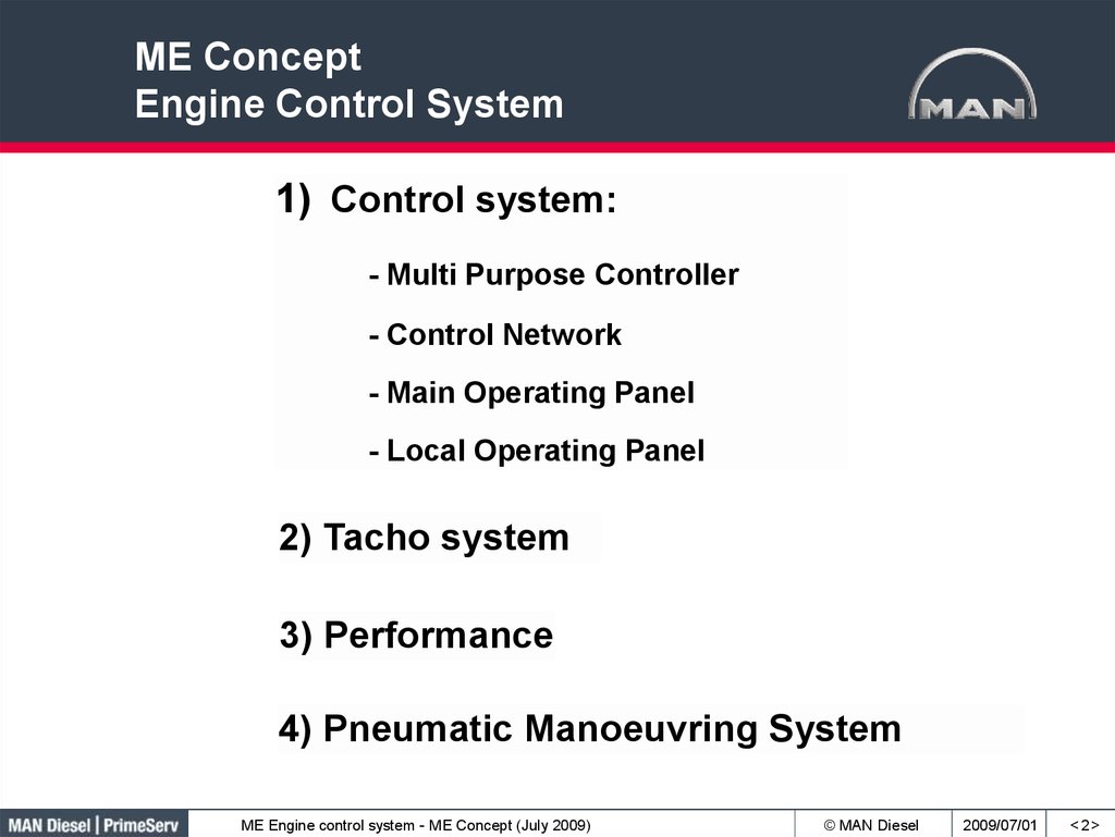
ME ConceptEngine Control System
1) Control system:
- Multi Purpose Controller
- Control Network
- Main Operating Panel
- Local Operating Panel
2) Tacho system
3) Performance
4) Pneumatic Manoeuvring System
ME Engine control system - ME Concept (July 2009)
© MAN Diesel
2009/07/01
<2>
3. Control Systems
Bridge CtrSystem
Engine Ctr
System
ME Engine control system - ME Concept (July 2009)
© MAN Diesel
2009/07/01
<3>
4. Engine Control System MPC & Control Network
Engine Control SystemMPC & Control Network
• The Multi Purpose Controllers are
identical hardware wise.
• They have different software
configurations.
• 2 redundant control networks are
connecting all Multi Purpose
Controllers and both Main Operating
Panels.
• A backup of the application- and
setup- software is stored on both
Main Operation Panels.
• At replacement, the new controller
is automatically configured with
correct software via the control
networks.
ME Engine control system - ME Concept (July 2009)
© MAN Diesel
2009/07/01
<4>
5. Multi Purpose Controller, MPC
24 VDC, isolated system, A is UPS2 separate 16 A breakers (A & B) for
every MPC
ME Engine control system - ME Concept (July 2009)
(Accessible by
authorized service
personnel only)
© MAN Diesel
2009/07/01
<5>
6. Multi Purpose Controller, MPC
Reset push buttonDIP Switches &
Battery for internal clock
LED indicator
DIP Switches
Power Plug
Fuses
ME Engine control system - ME Concept (July 2009)
© MAN Diesel
2009/07/01
<6>
7. Multi Purpose Controller, MPC
Multi Purpose ControllerAmplifier for FIVA (CCU’s) and
Hydraulic pumps (ACU’s)
’IP 66’ cabinet
ME Engine control system - ME Concept (July 2009)
© MAN Diesel
2009/07/01
<7>
8. Multi Purpose Controller LED Information Code
The LED gives information, either as a constant light or by flashing.A flashing LED is a coded message from the controller. The code consists of 2
digits:
1. Digit is given by red flashes on yellow/orange background
2. Digit is given by green flashes on yellow/orange background
The 2 digits are separated by a 1 sec. yellow/orange pulse.
ME Engine control system - ME Concept (July 2009)
© MAN Diesel
2009/07/01
<8>
9. Multi Purpose Controller LED Information Code
ME Engine control system - ME Concept (July 2009)© MAN Diesel
2009/07/01
<9>
10. Control Network
120 Ω120 Ω
B
B
A
A
MOP A
EICU A
EICU B
MOP B
A
A
B
B
Control room
Engine
J65 (A)
J66 (B)
A
ECU A
A
B
B
ECU B
C
A
B
2
Shield
1
120 Ω
120 Ω
A
A
A
A
A
CCU 1
CCU n
ACU 3
ACU 2
ACU 1
B
B
B
B
B
ME Engine control system - ME Concept (July 2009)
© MAN Diesel
2009/07/01
< 10 >
11. MPC’s Nordic Brasilia – 6S70ME-C
ME Engine control system - ME Concept (July 2009)© MAN Diesel
2009/07/01
< 11 >
12. Engine Interface Control Unit, EICU Interface to External Systems
Power managenentsystem
EICU B
EICU A
Man-handle
4 – 20 mA + stop signal
(RS 422)
Remote Control
System
(RS 422)
Alarm System
Safety System
Shutdown signals
to ECU + CCU
ME Engine control system - ME Concept (July 2009)
© MAN Diesel
2009/07/01
< 12 >
13. Engine Interface Control Unit, EICU Speed Setpoint
Pre defined RPM for starting.Stop
Gives the minimum speed set point
Gives the maximum speed set point
ONLY for CPP plants - Fixed speed set point when ’Bridge command take’ is active
Shut Down Stop
Speed set point reduced to Slow Down Speed
Speed set point set inside RPM range for shaft generator
Speed ramp up / down, 3 RPM / Sec. Not cancellable
80 – 100 % RPM in 90 min. on largebore engines. Cancelled by ’Increase Limits’
Modifies setpoint to be outside the barred speed range
Fine adjustment of speedset active
ME Engine control system - ME Concept (July 2009)
© MAN Diesel
2009/07/01
< 13 >
14. Engine Control Unit, ECU Start Block
Check list of conditions which must be inorder before engine start
One list for ’Standby’ and another list for
’FWE’ (Finished With Engine),
ME Engine control system - ME Concept (July 2009)
© MAN Diesel
2009/07/01
< 14 >
15. Engine Control Unit, ECU
In case of start failure,there will be 2
repeated starts with
increased fuel
(heavy start)
3 governor modes:
RPM – Torque - Index
2 Running modes:
Economy - Emission
In combination with manoeuvering handle: (nothing happens
while the handle is in ’Stop’ position)
Prepare Start:
Prelube and aux blower start
by pressing MOP or
moving man-handle.
Auto:
Slow turn valve - main starting air valve - fuel
Slow Turn: Only slow turning valve, no fuel
Air Run:
Air starting sequence, no fuel
ME Engine control system - ME Concept (July 2009)
© MAN Diesel
2009/07/01
< 15 >
16. Engine Control Unit, ECU Injection Profiles
ME Engine control system - ME Concept (July 2009)© MAN Diesel
2009/07/01
< 16 >
17. Engine Control Unit, ECU Governor
ECU A/B are the governors –calculating the needed fuel
index
Pre defined index for starting.
Max fuel set by C/E, for individual or all cylinders.
A certain Pscav allows a certain index
A certain RPM allows a certain index
A certain hydraulic pressure allows a certain index
ME Engine control system - ME Concept (July 2009)
© MAN Diesel
2009/07/01
< 17 >
18. Cylinder Control Unit, CCU
FIVA: Fuel Injection Valve ActuationProportional valve for fuel injct.
ON/OFF for exhaust operation.
FIVA feedback from
LVDT sensor, 4-20 mA
Fuel plunger position
4-20 mA feedback
Exh. valve spindle position
4-20 mA feedback used in
valve control
Starting air valve,
starting sequence
identical to MC engine
Cylinder lubricator ON/OFF
valve, feedrate controlled
by injection frequency
One CCU for every
cylinder
ME Engine control system - ME Concept (July 2009)
© MAN Diesel
2009/07/01
< 18 >
19. Starting Air Systems
MC-C designME-C design
Pilot air inlet
Blow-off
NC-valves
Connection
for
ECS
Starting air
distributor
Starting valves
ME Engine control system - ME Concept (July 2009)
Starting valves
© MAN Diesel
2009/07/01
< 19 >
20. Starting- and Pilot Air Valve
Starting air valvePilot air valve
ME Engine control system - ME Concept (July 2009)
© MAN Diesel
2009/07/01
< 20 >
21. Auxiliary Control Unit, ACU Blower Control
The blowers are starting one by one, to preventoverload of electrical system
In AUTO mode:
The blowers are started at ’Prepare Start’
At engine running they are controlled by the scavenge air
pressure, stop at 0.7 bar (time delay), start at 0.4 bar.
At engine stop they will continue running for default 15 min.
In Manual mode:
Controlled by the operator
ME Engine control system - ME Concept (July 2009)
© MAN Diesel
2009/07/01
< 21 >
22. Auxiliary Control Unit, ACU Pump Control
ECU AECU B
Electrically driven pumps 1 & 2 are controlled by ACU 1 & 2
Engine driven pumps 1, 2 & 3 are controlled by ACU 1, 2 & 3,
The control is modulated, based on the pressure setpoint
and the actual hydraulic pressure.
Engine driven pumps 4 & 5 are the same type as 1, 2 & 3
but are controlled digitally by ECU A & B, either maximum
AHEAD or maximum ASTERN.
If the engine is equipped with 4 or 5 engine driven pumps,
ECU A & B are not 100 % redundant
ME Engine control system - ME Concept (July 2009)
© MAN Diesel
2009/07/01
< 22 >
23. Multi Purpose Controller, MPC Summary
The MPC’s are software wise configured to4 different controller functions:
1) Engine Interface Conrol Unit – EICU
• 2 completely redundant units
• Handles the interface to external systems
2) Engine Control Unit – ECU
• 2 completely redundant units (except with more than 3 engine driven pumps)
• Handles the engine specific control functions (the govenor)
3) Cylinder Control Unit – CCU
• 1 for each cylinder unit, redundancy by multiplicity
• Handles the cylinder specific functions (fuel injection, exh. valve, cylinder lubrication and
starting air valves)
4) Auxilliary Control Unit – ACU
• 3 units, redundancy by multiplicity
• Handles the auxilliary systems (hydraulic power supply, aux blowers)
ME Engine control system - ME Concept (July 2009)
© MAN Diesel
2009/07/01
< 23 >
24. Engine Control System Control Panels
Bridge Control system isconnected to EICU
Engine Control Room Panel is
connected to EICU
Local Operating Panel LOP is
connected to ECU
ME Engine control system - ME Concept (July 2009)
© MAN Diesel
2009/07/01
< 24 >
25. Main Operating Panel, MOP
ME Engine control system - ME Concept (July 2009)© MAN Diesel
2009/07/01
< 25 >
26. Local Operating Panel (LOP) FPP
ME Engine control system - ME Concept (July 2009)© MAN Diesel
2009/07/01
< 26 >
27. Local Operating Panel (LOP) CPP
ME Engine control system - ME Concept (July 2009)© MAN Diesel
2009/07/01
< 27 >
28. Engine Control System Tacho System
There are 2 redundant tacho systems.System A
System B
Standard is:
angle encoders with one
reference sensor on the turning
wheel (A-system)
Option is sensors at the turning wheel
ME Engine control system - ME Concept (July 2009)
© MAN Diesel
2009/07/01
< 28 >
29. Tacho System
ME Engine control system - ME Concept (July 2009)© MAN Diesel
2009/07/01
< 29 >
30. Tacho System Angle Encoders
ECU’s4001-A
4002-A
TSA-A
+
4003-A
CCU’s
4004-A
4001-B
4002-B
4003-B
TSA-B
4004-B
Cable to TSA-A box
Cable to TSA-B box
Q2A
MSA
Turning wheel
reference
Q2B
MMA
Q1A
Q1B
MMB
0 deg
(TDC 1)
90 deg
ATDC
45 deg
ATDC
MSA
(not used)
MSB
Tacho Encoder
Angle
encoderAA
ME Engine control system - ME Concept (July 2009)
Tacho
Encoder
B B
Angle
encoder
© MAN Diesel
2009/07/01
< 30 >
31. Tacho system Angle encoder A + B
System A (powered from ECU A)MMA = Marker Master A
TDC 1
Q2A
Q1B
Q1A
MSA = Marker Slave A
MMA 0 deg
Q1A = Quadratur 1A
Q2A = Quadratur 2A
MMB 45 deg
System B (powered from ECU B)
Q2B
MMB = Marker Master B
MSB = Marker Slave B
MSA 90 deg
Q1B = Quadratur 1B
(Turning wheel
Reference)
Q2B = Quadratur 2B
MSB 135 deg
Pos
MMA
MMB
MSA
MSB
0-44
True
False
False
False
ME Engine control system - ME Concept (July 2009)
45-89
True
True
False
False
90-134 135-179 180-224 225-269 270-314 315-359
True
True
False
False
False
False
True
True
True
False
False
False
True
True
True
True
False
False
False
True
True
True
True
False
© MAN Diesel
2009/07/01
< 31 >
32. Tacho System, Angle Encoders
ME Engine control system - ME Concept (July 2009)© MAN Diesel
2009/07/01
< 32 >
33. Tacho System Amplifier Boxes, TSA
ME Engine control system - ME Concept (July 2009)© MAN Diesel
2009/07/01
< 33 >
34. Tacho System, Semicircular Ring
ME Engine control system - ME Concept (July 2009)© MAN Diesel
2009/07/01
< 34 >
35. Tacho System, Master Slave A, MSA, on AFT end of Engine
ME Engine control system - ME Concept (July 2009)© MAN Diesel
2009/07/01
< 35 >
36. Tacho System Trigger Rings + Sensors (option)
• 2 redundant set of sensors.• Each set measure engine speed
and crankshaft position for
synchronization of the control
events.
• Each set consist of four sensors. Two
quadrature sensors measure on a
trigger ring with 360 teeth and two
marker sensors measures on a
semicircular ring.
Triggersegment with a sine-curved toothprofile The total trigger ring is built by 8 equal
segments.
ME Engine control system - ME Concept (July 2009)
© MAN Diesel
2009/07/01
< 36 >
37. Performance
By changing the exh. valve closing timing, the Pcompcan be adjusted, and then the Pmax can be kept
constant in a bigger range.
The maximum pressure rise (Pmax –Pcomp) has the the
same limits as for MC engine because the combustion
chambers are identical. (i.e. 35 bar)
ME Engine control system - ME Concept (July 2009)
© MAN Diesel
2009/07/01
< 37 >
38. Pscav, Pcomp & Pmax
41 Bar32 Bar
Pscav, Pcomp & Pmax
Late closing of
Exh. V/V
Early closing of
Exh. V/V
Late closing will here cause too
high ΔP (Pmax – Pcomp)
ME Engine control system - ME Concept (July 2009)
© MAN Diesel
2009/07/01
39. Pneumatic Manoeuvring System
2 Valves for Redundancy,93 Controlled from
ECU A, 94 from ECU B
ME Engine control system - ME Concept (July 2009)
© MAN Diesel
2009/07/01
< 39 >