


 Информатика
Похожие презентации:


")
")


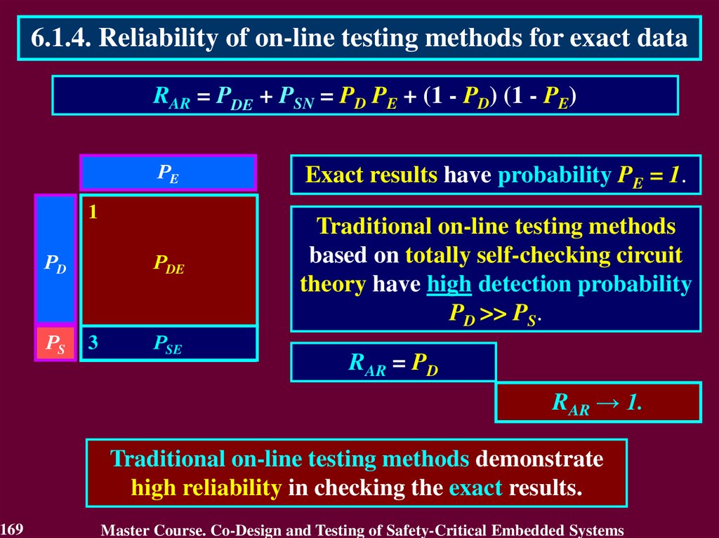
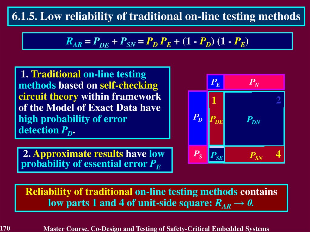
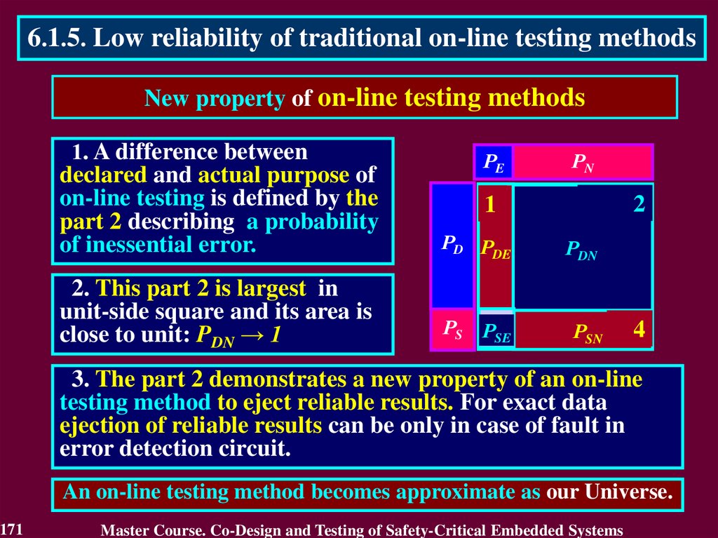
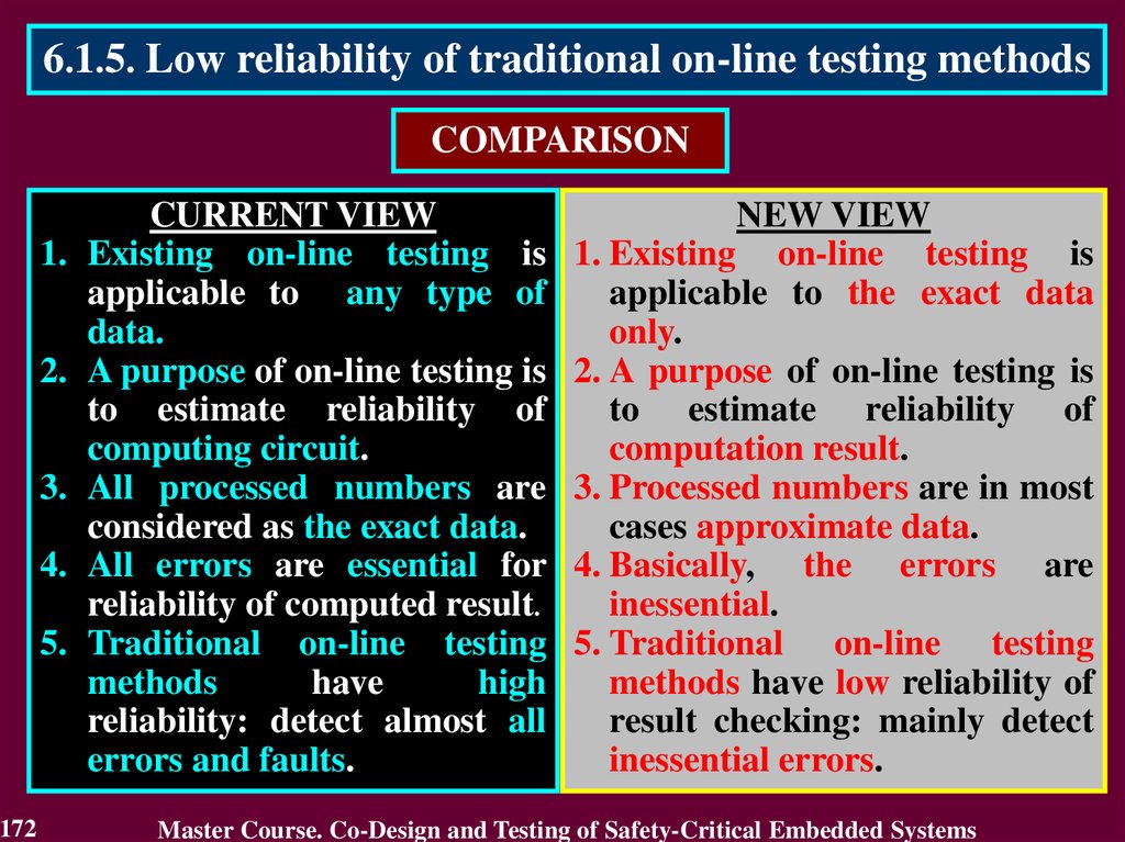
Co-design and testing of safety-critical embedded systems
1.
Odessa National Polytechnic UniversityMaster Course
CO-DESIGN AND TESTING
OF SAFETY-CRITICAL
EMBEDDED SYSTEMS
Alexander Drozd
drozd@ukr.net
1
Master Course. Co-Design and Testing of Safety-Critical Embedded Systems
2.
General course information1. Object of Study:
Concepts of Safety-Critical Embedded Systems (S-CES):
Co-design and Testing.
2. Prerequisites:
Computer Systems and System Analysis; Foundations of Logic
Engineering; Probability Theory; Theory of Self-Checking Circuits;
Modeling Foundation knowledge.
3. Subject of Study:
Principles, methods and techniques in co-design and testing of S-CES.
4. Aims:
Acquisition of knowledge about methods and techniques in co-design
and testing of S-CES and their components.
2
Master Course. Co-Design and Testing of Safety-Critical Embedded Systems
3.
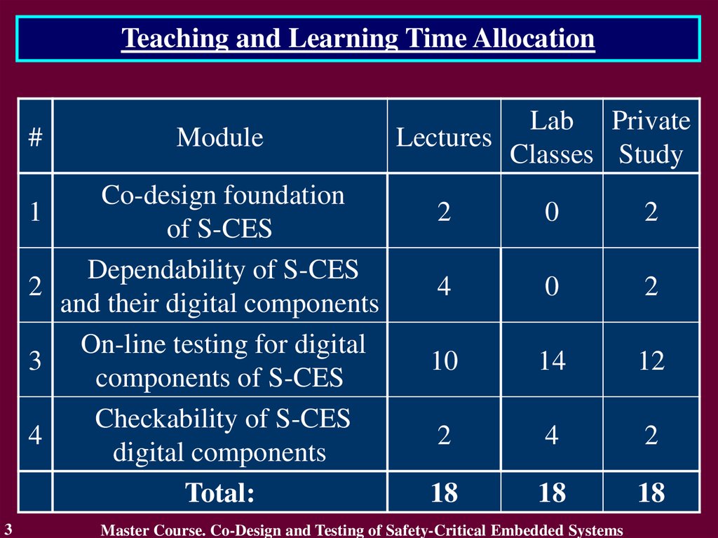
Teaching and Learning Time Allocation#
1
2
3
4
3
Module
Co-design foundation
of S-CES
Dependability of S-CES
and their digital components
On-line testing for digital
components of S-CES
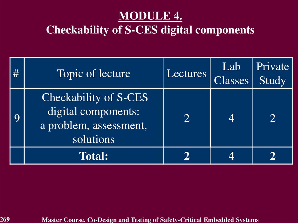
Checkability of S-CES
digital components
Total:
Lab Private
Lectures
Classes Study
2
0
2
4
0
2
10
14
12
2
4
2
18
18
18
Master Course. Co-Design and Testing of Safety-Critical Embedded Systems
4.
MODULE 1.Co-design foundation of S-CES
#
Topic of lecture
Traditional ideas of S-CES
1
co-design
Total:
4
Lab Private
Lectures
Classes Study
2
0
2
2
0
2
Master Course. Co-Design and Testing of Safety-Critical Embedded Systems
5.
MODULE 1. Co-Design Foundation of S-CESLecture 1. Traditional ideas of S-CES co-design
1.1. Component approach
1.2. Standards regulating legislative of S-CES
1.3. Life-cycle of S-CES
5
Master Course. Co-Design and Testing of Safety-Critical Embedded Systems
6.
1.1. Component ApproachComponent-based technology is information technology based on
component representation of systems and on use of well-tested
software and hardware products.
COTS-approach (Commercial-Off-The-Shelf) – reuse of
commercial components.
CrOTS-approach (Critical-Off-The-Shelf) – reuse of components
in critical applications.
Component approach constitutes the use of library components
developed formerly and commonly employed in commercial and
critical applications, including the components of one’s own design.
6
Master Course. Co-Design and Testing of Safety-Critical Embedded Systems
7.
1.2. Standards regulating legislative of S-CESIEC 61508 (general for
electronics & digital)
and
EN 50126 (Railway)
DO 178-B (Avionics)
and
ISO 26262 (Automotive)
IEC 61513
(Nuclear power plants)
and
IEC 62061 (Machines)
ISO
26262
Auto
DO-178B
Avionic
SW
IEC
61513
NPP
IEC – International Electrotechnical Commission
7
IEC
61508
(general)
EN
50126
Rail
IEC
62061
Machines
This slide from presentation of
M. Fusani ISTI - CNR, Pisa, Italy
Master Course. Co-Design and Testing of Safety-Critical Embedded Systems
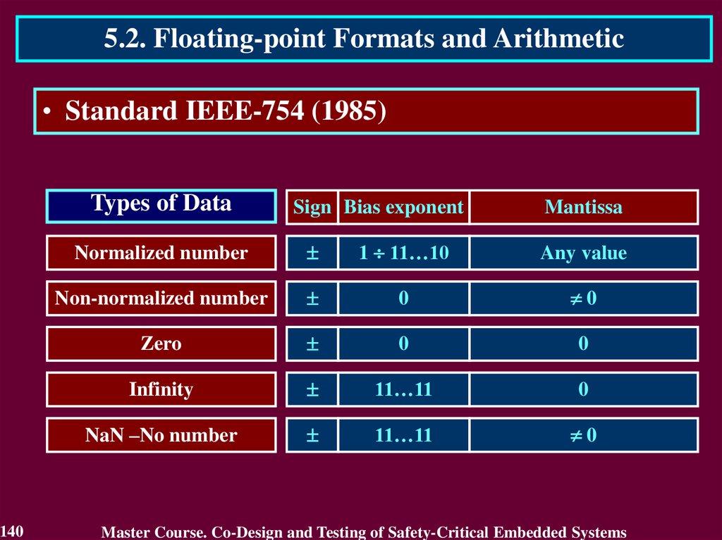
8.
1.2. Standards regulating legislative of S-CESIEC 61508 – Safety of electrical, electronic and
programmable systems important to safety
IEC 61508-1:1998 ‘General requirements’
IEC 61508-2:2000 ‘Requirements to electrical, electronic and
programmable systems’
IEC 61508-3:1998 ‘Requirements to software’
IEC 61508-4:1998 ‘Definitions to Abbreviations’
IEC 61508-5:1998 ‘Examples of methods for determining safety integrity
levels’
IEC 61508-6:2000 ‘Guide for use of IEC 61508-2 and IEC 61508-3’
IEC 61508-7:2000 ‘Overview of techniques and measures’
8
Master Course. Co-Design and Testing of Safety-Critical Embedded Systems
9.
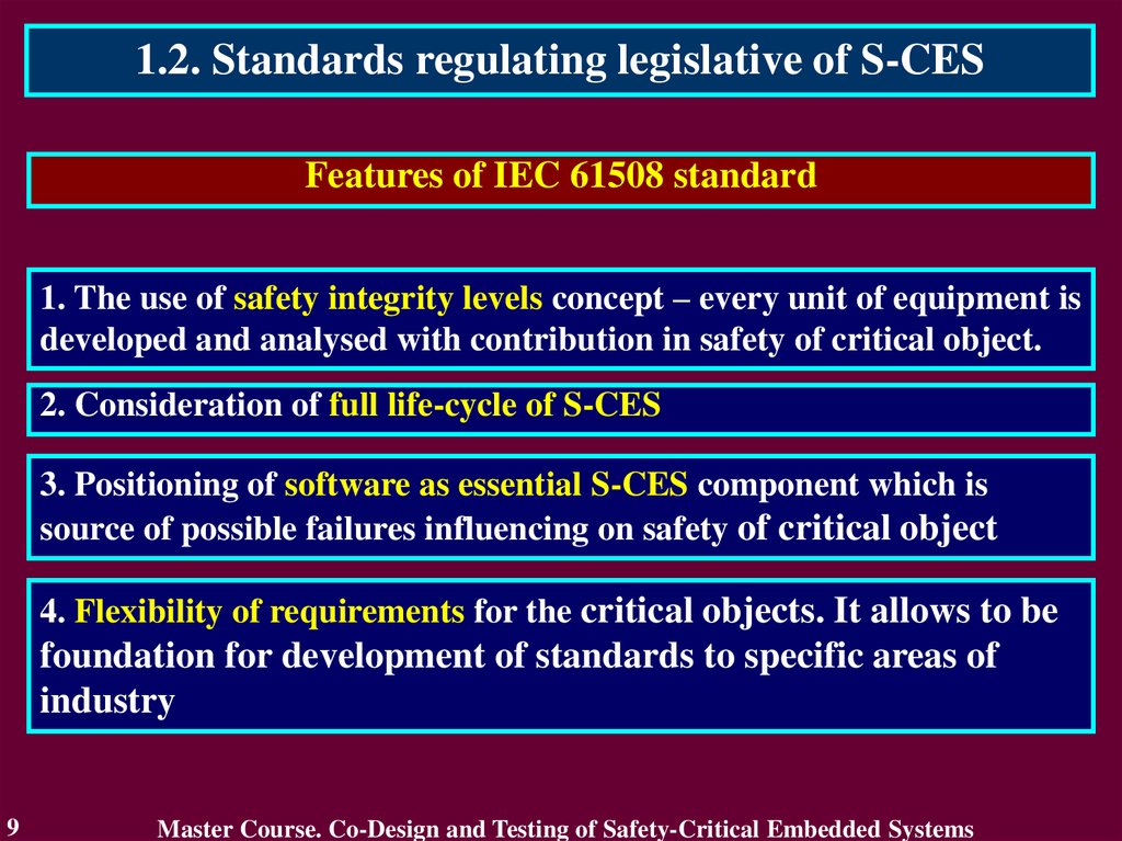
1.2. Standards regulating legislative of S-CESFeatures of IEC 61508 standard
1. The use of safety integrity levels concept – every unit of equipment is
developed and analysed with contribution in safety of critical object.
2. Consideration of full life-cycle of S-CES
3. Positioning of software as essential S-CES component which is
source of possible failures influencing on safety of critical object
4. Flexibility of requirements for the critical objects. It allows to be
foundation for development of standards to specific areas of
industry
9
Master Course. Co-Design and Testing of Safety-Critical Embedded Systems
10.
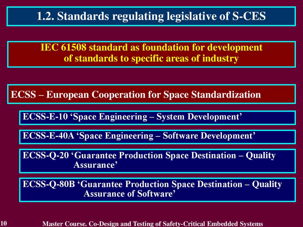
1.2. Standards regulating legislative of S-CESIEC 61508 standard as foundation for development
of standards to specific areas of industry
ECSS – European Cooperation for Space Standardization
ECSS-E-10 ‘Space Engineering – System Development’
ECSS-E-40A ‘Space Engineering – Software Development’
ECSS-Q-20 ‘Guarantee Production Space Destination – Quality
Assurance’
ECSS-Q-80B ‘Guarantee Production Space Destination – Quality
Assurance of Software’
10
Master Course. Co-Design and Testing of Safety-Critical Embedded Systems
11.
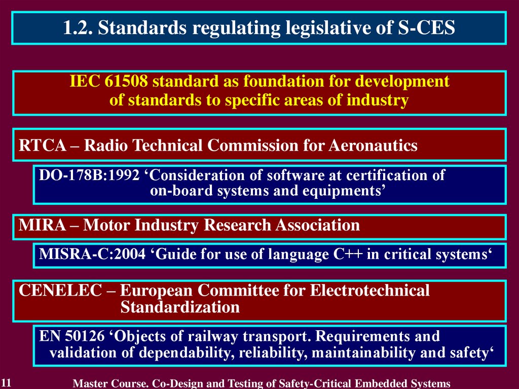
1.2. Standards regulating legislative of S-CESIEC 61508 standard as foundation for development
of standards to specific areas of industry
RTCA – Radio Technical Commission for Aeronautics
DO-178B:1992 ‘Consideration of software at certification of
on-board systems and equipments’
MIRA – Motor Industry Research Association
MISRA-C:2004 ‘Guide for use of language C++ in critical systems‘
CENELEC – European Committee for Electrotechnical
Standardization
EN 50126 ‘Objects of railway transport. Requirements and
validation of dependability, reliability, maintainability and safety‘
11
Master Course. Co-Design and Testing of Safety-Critical Embedded Systems
12.
1.2. Standards regulating legislative of S-CESIEC 61508 standard as foundation for development
of standards to specific areas of industry
IAEA – International Atomic Energy Agency
IAEA NS-G-1.1 ‘Software and computer-based systems important
to safety in nuclear power plants’
IAEA NS-G-1.2 ‘Safety assessment and verification for nuclear
power plants’
IAEA NS-G-1.3 ‘Instrumentation and control systems important
to safety in nuclear power plants’
12
Master Course. Co-Design and Testing of Safety-Critical Embedded Systems
13.
1.2. Standards regulating legislative of S-CESIEC 61508 standard as foundation for development
of standards to specific areas of industry
IEC – International Technical Commission
IEC 60780:1998 ‘Nuclear power plants – Electrical equipment of the
safety system - Qualification’
IEC 60880:2006 ‘Nuclear power plants – Instrumentation and control
systems important to safety – Software aspects for
computer-based systems performing category A functions’
IEC 60980:1989 ‘Recommended practices for seismic qualification of
electrical equipment of the safety system for nuclear
generating stations’
IEC 60987:2007 ‘Nuclear power plants – Instrumentation and control
systems important to safety – Hardware design
requirements for computer-based systems’
13
Master Course. Co-Design and Testing of Safety-Critical Embedded Systems
14.
1.2. Standards regulating legislative of S-CESIEC 61508 standard as foundation for development
of standards to specific areas of industry
IEC – International Technical Commission
IEC 61226:2005 ‘Nuclear power plants – Instrumentation and control
systems important to safety – Classification of instrumentation
and control functions’
IEC 61513:2001 ‘Nuclear power plants – Instrumentation and control
systems important to safety – General requirements for systems’
IEC 62138:2004 ‘Nuclear power plants – Instrumentation and control
systems important to safety – Software aspects for
computer-based systems performing category B or C functions’
IEC 62340:2007 ‘Nuclear power plants – Instrumentation and control
systems important to safety – Requirements for coping with
common cause failure’
14
Master Course. Co-Design and Testing of Safety-Critical Embedded Systems
15.
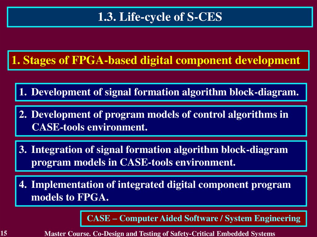
1.3. Life-cycle of S-CES1. Stages of FPGA-based digital component development
1. Development of signal formation algorithm block-diagram.
2. Development of program models of control algorithms in
CASE-tools environment.
3. Integration of signal formation algorithm block-diagram
program models in CASE-tools environment.
4. Implementation of integrated digital component program
models to FPGA.
CASE – Computer Aided Software / System Engineering
15
Master Course. Co-Design and Testing of Safety-Critical Embedded Systems
16.
1.3. Life-cycle of S-CES2. Results of FPGA-based digital component development
1. Block-diagrams according to control algorithms.
2. Program models of control algorithms in CASE-tools
environment.
3. Integrated program model of control algorithms in CASEtools environment.
4. FPGA with implemented integrated program model.
16
Master Course. Co-Design and Testing of Safety-Critical Embedded Systems
17.
1.3. Life-cycle of S-CES3. Verification stages of FPGA-based digital component
development
1. Verification of block-diagrams according to control
algorithms.
2. Verification of program models of control algorithms in
CASE-tools environment.
3. Verification of integrated program model in CASE-tools
environment.
4. Verification of FPGA with implemented integrated program
model.
17
Master Course. Co-Design and Testing of Safety-Critical Embedded Systems
18.
1.3. Life-cycle of S-CES2. A life-cycle of FPGA-based S-CES
Stages
of
development
Results
of
development
Verification
stages
18
System
requirements
specification
Development of
block-diagrams
according to
control
algorithms
Development of
program models
of control
algorithms in
CASE-tools
environment
Block-diagrams
according to
control
algorithms
Verification of
block-diagrams
according to
control
algorithms
Integration of
program models
of control
algorithms in
CASE-tools
environment
Program models
of control
algorithms in
CASE-tools
environment
Verification of
program models
of control
algorithms in
CASE-tools
environment
Implementation
of integrated
program model
to FPGA
Integrated
program model
of control
algorithms in
CASE-tools
environment
Verification of
integrated
program model
in CASE-tools
environment
System
integration
FPGA with
implemented
integrated
program model
Verification of
FPGA with
implemented
integrated
program model
Master Course. Co-Design and Testing of Safety-Critical Embedded Systems
Analysis of
verifycation
results
19.
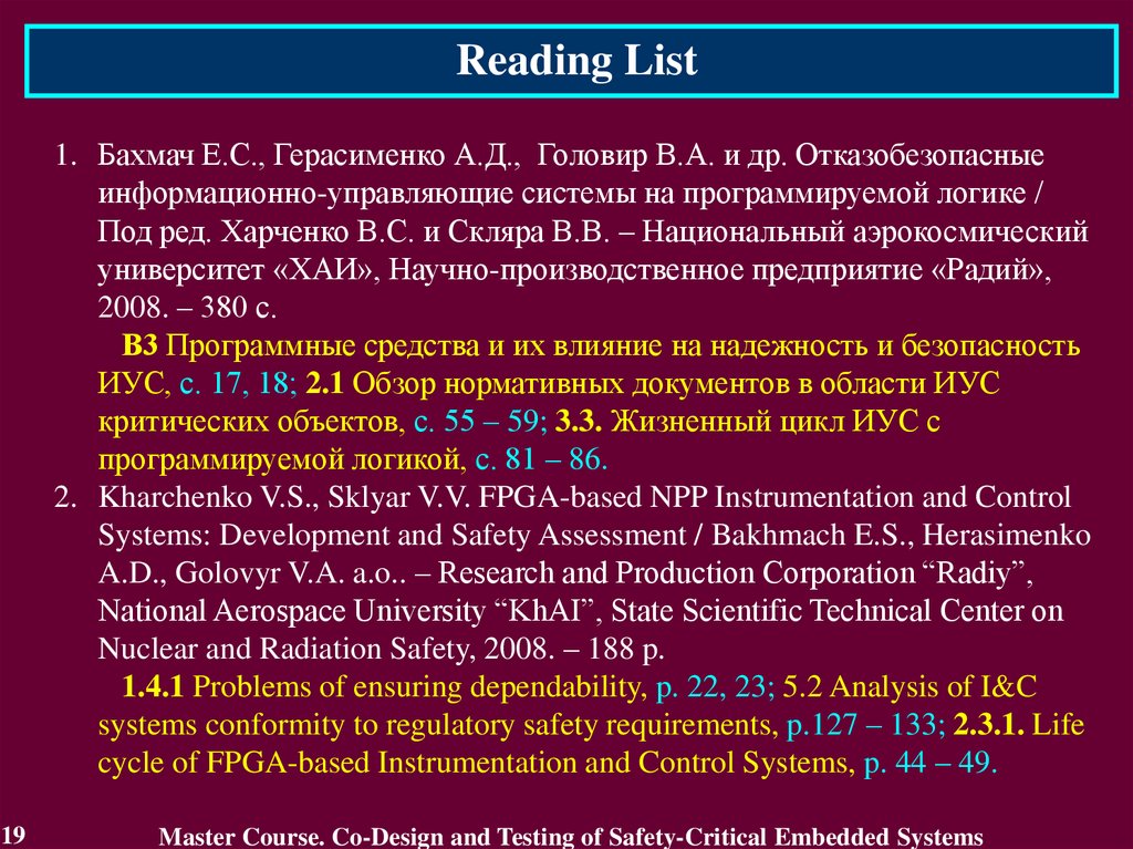
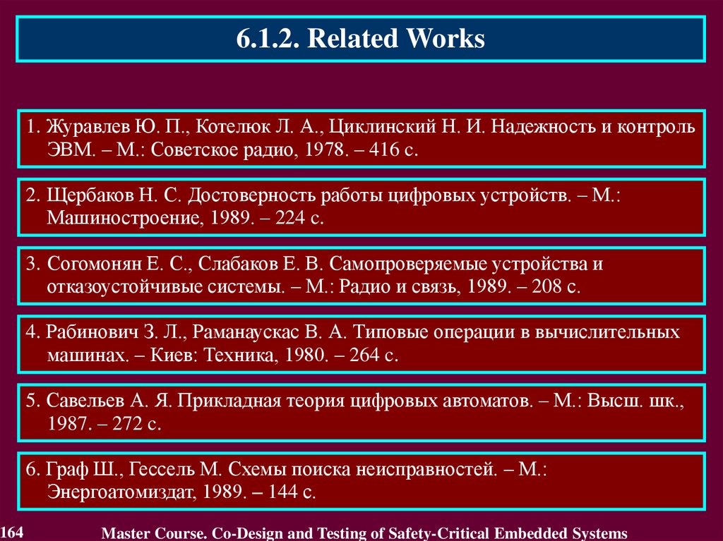
Reading List1. Бахмач Е.С., Герасименко А.Д., Головир В.А. и др. Отказобезопасные
информационно-управляющие системы на программируемой логике /
Под ред. Харченко В.С. и Скляра В.В. – Национальный аэрокосмический
университет «ХАИ», Научно-производственное предприятие «Радий»,
2008. – 380 с.
В3 Программные средства и их влияние на надежность и безопасность
ИУС, с. 17, 18; 2.1 Обзор нормативных документов в области ИУС
критических объектов, с. 55 – 59; 3.3. Жизненный цикл ИУС с
программируемой логикой, с. 81 – 86.
2. Kharchenko V.S., Sklyar V.V. FPGA-based NPP Instrumentation and Control
Systems: Development and Safety Assessment / Bakhmach E.S., Herasimenko
A.D., Golovyr V.A. a.o.. – Research and Production Corporation “Radiy”,
National Aerospace University “KhAI”, State Scientific Technical Center on
Nuclear and Radiation Safety, 2008. – 188 p.
1.4.1 Problems of ensuring dependability, p. 22, 23; 5.2 Analysis of I&C
systems conformity to regulatory safety requirements, p.127 – 133; 2.3.1. Life
cycle of FPGA-based Instrumentation and Control Systems, p. 44 – 49.
19
Master Course. Co-Design and Testing of Safety-Critical Embedded Systems
20.
Conclusion1. Co-design of S-CES is based on traditional ideas such as
Component approach, Standards regulating legislative and
Life-cycle of S-CES
2. Component approach constitutes the use of library components
developed formerly and commonly employed in commercial and
critical applications, including the components of one’s own
design.
3. The main standard is IEC 61508 – Safety of electrical, electronic
and programmable systems important to safety.
4. Life-cycle of FPGA-based S-CES digital component contains 4
stages of development with verification of results obtained on
every stage.
20
Master Course. Co-Design and Testing of Safety-Critical Embedded Systems
21.
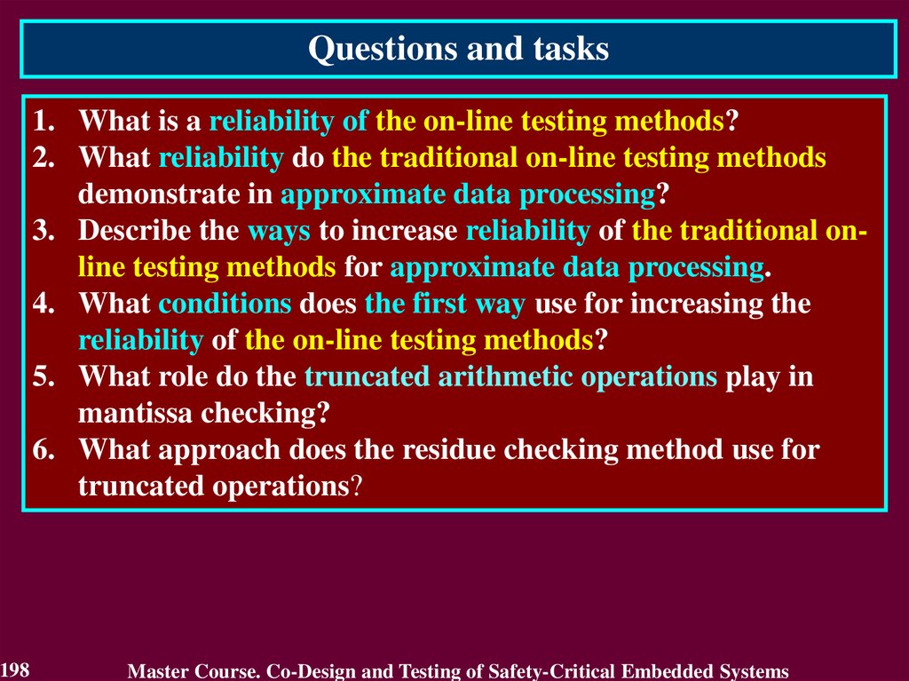
Questions and tasks1.
2.
3.
4.
5.
21
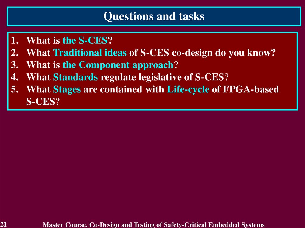
What is the S-CES?
What Traditional ideas of S-CES co-design do you know?
What is the Component approach?
What Standards regulate legislative of S-CES?
What Stages are contained with Life-cycle of FPGA-based
S-CES?
Master Course. Co-Design and Testing of Safety-Critical Embedded Systems
22.
MODULE 2.Dependability of S-CES
and their digital components
#
Topic of lecture
Foundation of
2
Dependability
Fault Tolerance of S-CES
3
and their digital components
Total:
22
Lab Private
Lectures
Classes Study
2
0
1
2
0
1
4
0
2
Master Course. Co-Design and Testing of Safety-Critical Embedded Systems
23.
MODULE 2. Dependability of S-CESand their digital components
Lecture 2. Foundation of Dependability
2.1. Introduction into dependability
2.2. Dependability Threats
2.3. Dependability Attributes
2.4. Dependability Measures
2.5. Safety and Reliability
2.6. Forms of Dependability Requirements
2.7. The Means to attain Dependability Techniques
23
Master Course. Co-Design and Testing of Safety-Critical Embedded Systems
24.
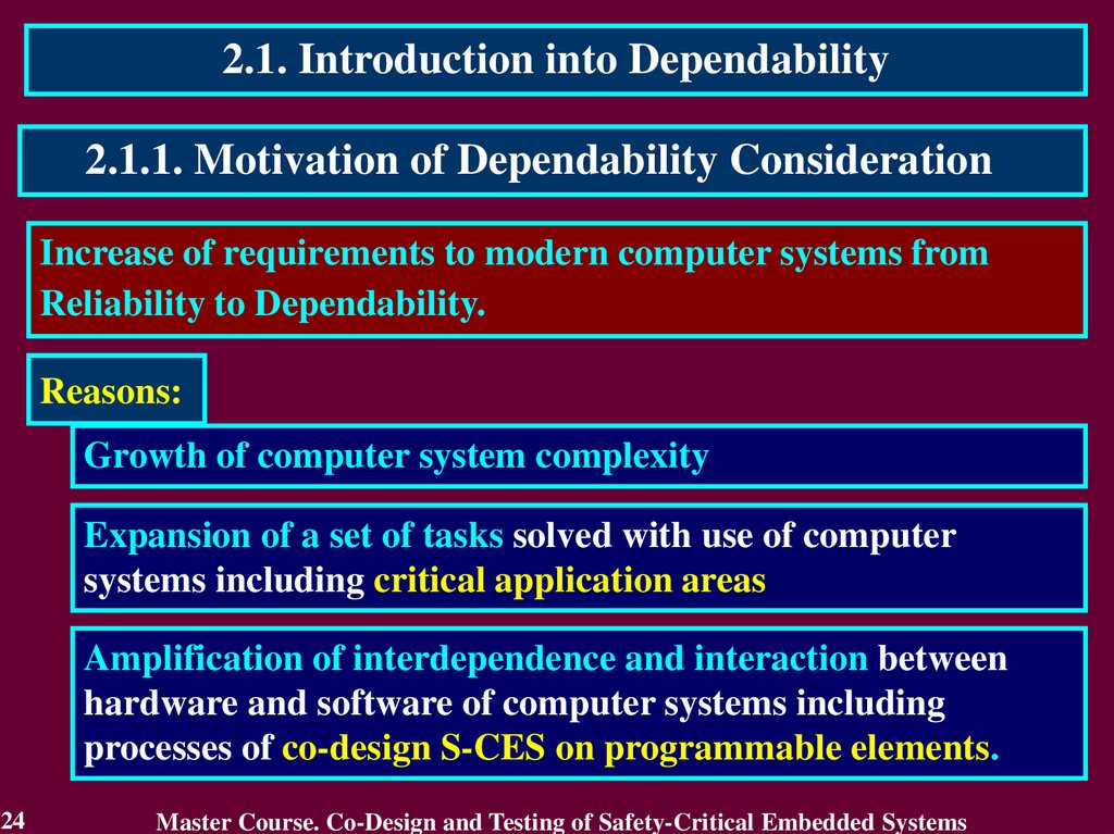
2.1. Introduction into Dependability2.1.1. Motivation of Dependability Consideration
Increase of requirements to modern computer systems from
Reliability to Dependability.
Reasons:
Growth of computer system complexity
Expansion of a set of tasks solved with use of computer
systems including critical application areas
Amplification of interdependence and interaction between
hardware and software of computer systems including
processes of co-design S-CES on programmable elements.
24
Master Course. Co-Design and Testing of Safety-Critical Embedded Systems
25.
2.1.2. Related WorksDifferent aspects of Dependability, principles of construction and realization
of dependable computer systems have been studied for the last two decades.
1. Avizienis A., Laprie J.-C. Dependable Computing: From Concepts to
Application // IEEE Transactions on Computers, 1986. Vol. 74, No. 5. P. 629-638.
Authors formulated the principle of “Dependable Computing” as
computation resistant to hardware and software failures (caused by their
defects brought in design and not revealed in the course of detected).
2. Dobson I., Randell B. Building Reliable Secure Computing Systems out of
Unreliable Insecure components // Proc. of IEEE Conference on Security and
Privacy, Oakland, USA. 1986. P. 186-193.
Authors defined “Secure-Fault Tolerance” and proposed a principle of
its realization for various types of computer systems.
3. Avizienis A., Laprie J.-C, Randell B., Landwehr C. Basic Concepts and
Taxonomy of Dependable and Secure Computing // IEEE Transactions on
Dependable and Secure Computing, 2004. Vol. 1. No. 1. P. 11-33.
25
Master Course. Co-Design and Testing of Safety-Critical Embedded Systems
26.
2.1.3. Definition of DependabilityDependability is ability to avoid service failures that are more
frequent or more severe than is acceptable. When service failures are
more frequent or more severe than acceptable: dependability failure.
Attributes - properties expected from the system and according to
which assessment of service quality resulting from threats and means
opposing to them is conducted.
Means - methods and techniques enabling
1) to provide service on which reliance can be placed
2) to have confidence in its ability.
Threats - undesired (not unexpected) circumstances causing or
resulting from undependability (reliance cannot or will not any
longer be placed on the service.
26
Master Course. Co-Design and Testing of Safety-Critical Embedded Systems
27.
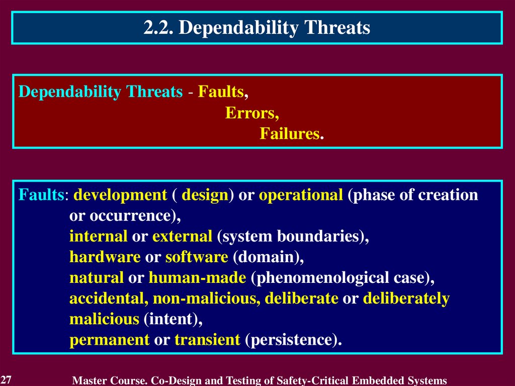
2.2. Dependability ThreatsDependability Threats - Faults,
Errors,
Failures.
Faults: development ( design) or operational (phase of creation
or occurrence),
internal or external (system boundaries),
hardware or software (domain),
natural or human-made (phenomenological case),
accidental, non-malicious, deliberate or deliberately
malicious (intent),
permanent or transient (persistence).
27
Master Course. Co-Design and Testing of Safety-Critical Embedded Systems
28.
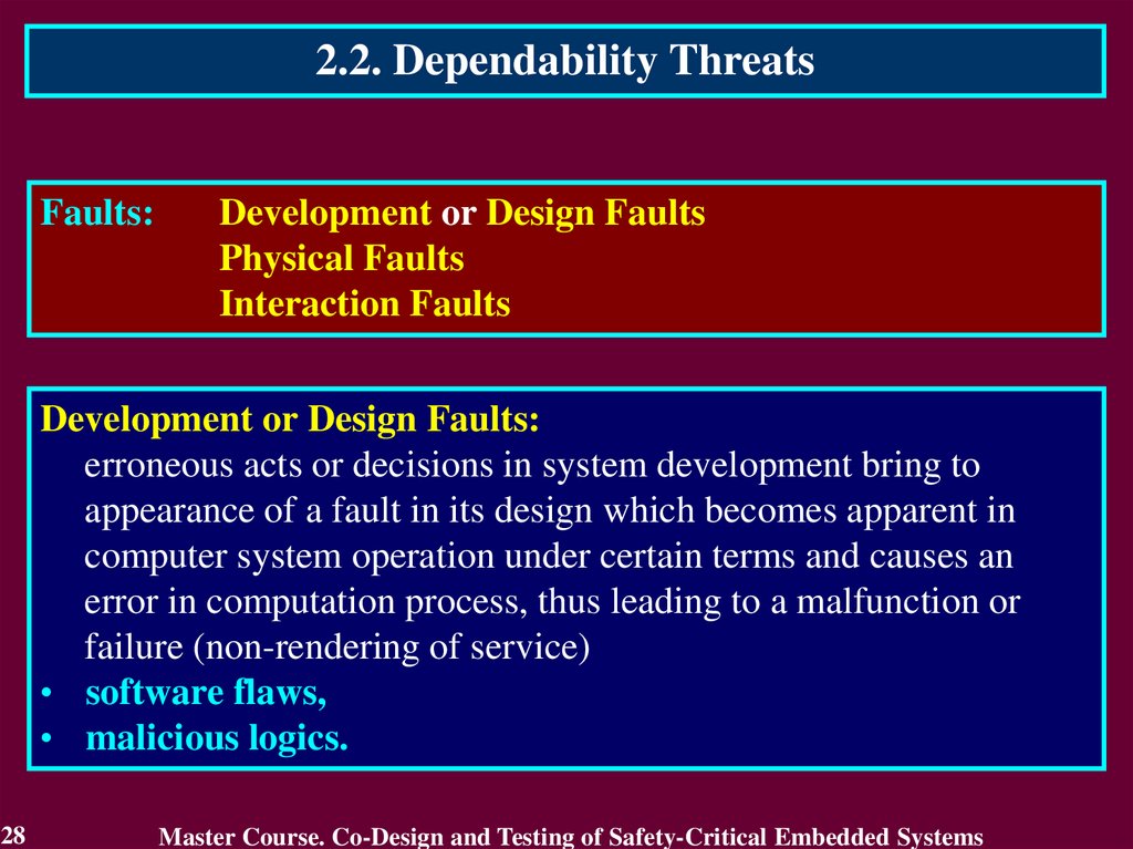
2.2. Dependability ThreatsFaults:
Development or Design Faults
Physical Faults
Interaction Faults
Development or Design Faults:
erroneous acts or decisions in system development bring to
appearance of a fault in its design which becomes apparent in
computer system operation under certain terms and causes an
error in computation process, thus leading to a malfunction or
failure (non-rendering of service)
• software flaws,
• malicious logics.
28
Master Course. Co-Design and Testing of Safety-Critical Embedded Systems
29.
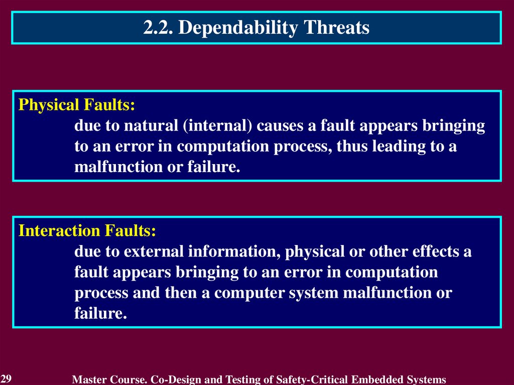
2.2. Dependability ThreatsPhysical Faults:
due to natural (internal) causes a fault appears bringing
to an error in computation process, thus leading to a
malfunction or failure.
Interaction Faults:
due to external information, physical or other effects a
fault appears bringing to an error in computation
process and then a computer system malfunction or
failure.
29
Master Course. Co-Design and Testing of Safety-Critical Embedded Systems
30.
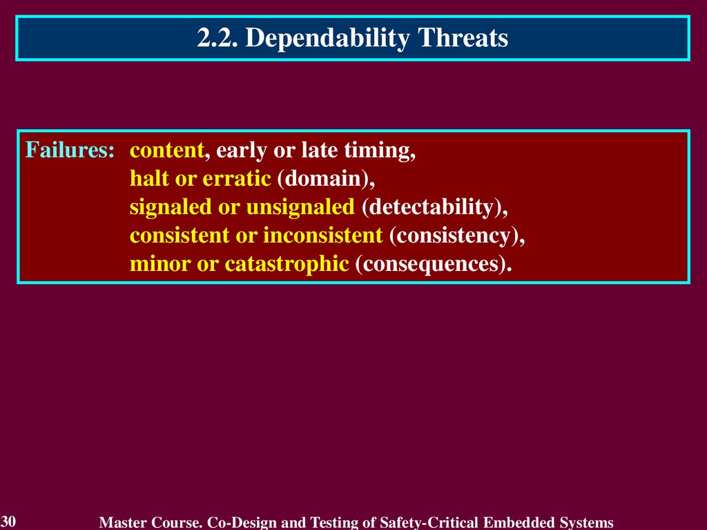
2.2. Dependability ThreatsFailures: content, early or late timing,
halt or erratic (domain),
signaled or unsignaled (detectability),
consistent or inconsistent (consistency),
minor or catastrophic (consequences).
30
Master Course. Co-Design and Testing of Safety-Critical Embedded Systems
31.
2.2. Dependability ThreatsFault error failure chain is a way from correct service up to
incorrect service.
Fault
Short-circuit in
memory chip
First written to by program
Fault
activation
Error
Wrong bit value
Read by program, cascade of
erroneous results
This slide from presentation
of Felicita Di Giandomenico
ISTI - CNR, Pisa, Italy
31
Error
propagation
Failure
Erroneous output
Master Course. Co-Design and Testing of Safety-Critical Embedded Systems
32.
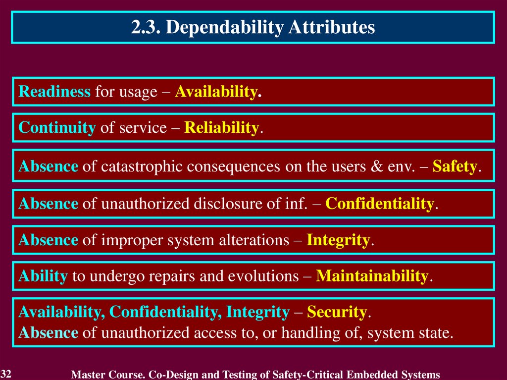
2.3. Dependability AttributesReadiness for usage – Availability.
Continuity of service – Reliability.
Absence of catastrophic consequences on the users & env. – Safety.
Absence of unauthorized disclosure of inf. – Confidentiality.
Absence of improper system alterations – Integrity.
Ability to undergo repairs and evolutions – Maintainability.
Availability, Confidentiality, Integrity – Security.
Absence of unauthorized access to, or handling of, system state.
32
Master Course. Co-Design and Testing of Safety-Critical Embedded Systems
33.
2.4. Dependability MeasuresThe alternation of correct-incorrect service delivery is quantified
to define the Measures of Dependability:
Reliability: a measure of the continuous delivery of correct
service – or the time to failure;
Availability: a measure of the delivery of correct service with
respect to the alternation of correct and incorrect
service;
Maintainability: a measure of the time to service restoration
since the last failure occurrence.
33
Master Course. Co-Design and Testing of Safety-Critical Embedded Systems
34.
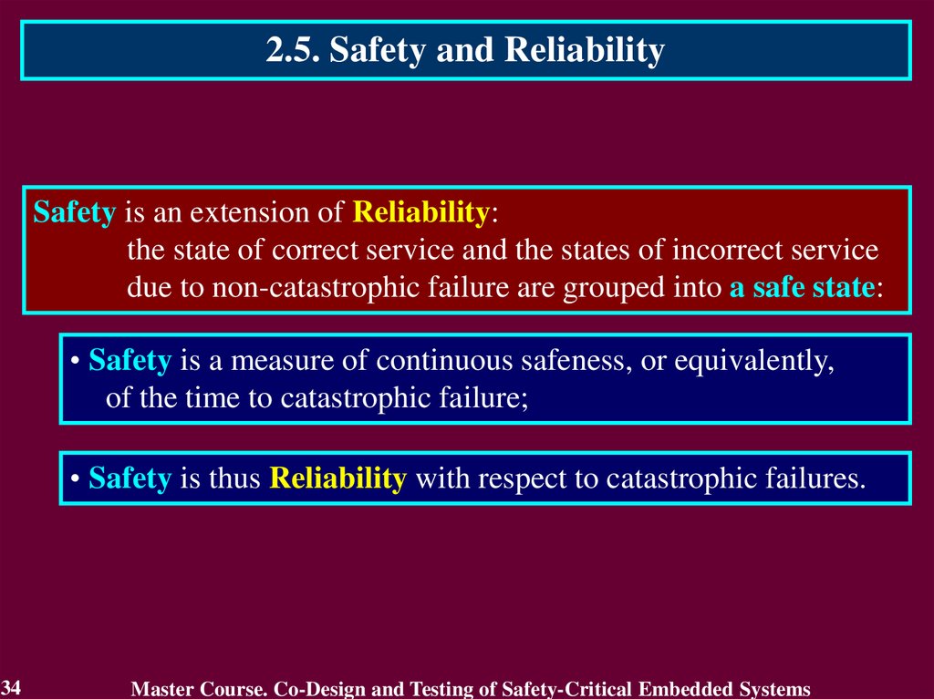
2.5. Safety and ReliabilitySafety is an extension of Reliability:
the state of correct service and the states of incorrect service
due to non-catastrophic failure are grouped into a safe state:
• Safety is a measure of continuous safeness, or equivalently,
of the time to catastrophic failure;
• Safety is thus Reliability with respect to catastrophic failures.
34
Master Course. Co-Design and Testing of Safety-Critical Embedded Systems
35.
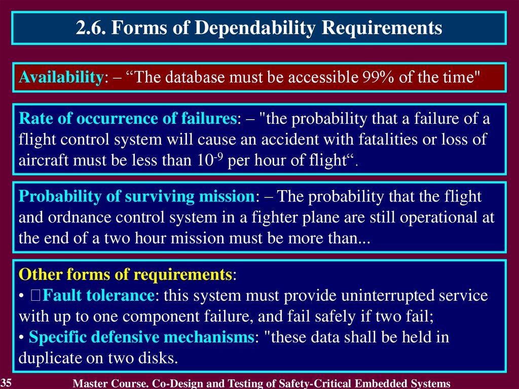
2.6. Forms of Dependability RequirementsAvailability: – “The database must be accessible 99% of the time"
Rate of occurrence of failures: – "the probability that a failure of a
flight control system will cause an accident with fatalities or loss of
aircraft must be less than 10-9 per hour of flight“.
Probability of surviving mission: – The probability that the flight
and ordnance control system in a fighter plane are still operational at
the end of a two hour mission must be more than...
Other forms of requirements:
• Fault tolerance: this system must provide uninterrupted service
with up to one component failure, and fail safely if two fail;
• Specific defensive mechanisms: "these data shall be held in
duplicate on two disks.
35
Master Course. Co-Design and Testing of Safety-Critical Embedded Systems
36.
2.7. The Means to attain Dependability TechniquesThe development of a Dependable Computing System calls for
the combined utilization of a set of four techniques:
• Fault prevention: how to prevent the occurrence or
introduction of faults;
• Fault removal: how to reduce the number or severity of faults;
• Fault forecasting: how to estimate the present number, the
future incidence and the likely consequences of faults.
• Fault tolerance: how to deliver correct service in the presence
of faults.
36
Master Course. Co-Design and Testing of Safety-Critical Embedded Systems
37.
2.7.1. Fault PreventionFault Prevention is attained by quality control techniques employed
during the design and manufacturing of hardware and software:
• They include structured programming, information hiding,
modularization, etc., for software, and rigorous design rules
and selection of high-quality, mass-manufactured hardware
components for hardware.
• Simple design, possibly at the cost of constraining functionality
or increasing cost
• Formal proof of important properties of the design
• Provision of appropriate operating environment (air
conditioning, protection against mechanical damage) intend to
prevent operational physical faults, while training, rigorous
procedures for maintenance, ‘foolproof’ packages, intend to
prevent interaction faults.
37
Master Course. Co-Design and Testing of Safety-Critical Embedded Systems
38.
2.7.2. Fault RemovalFault Removal is performed both during the development, and
during the operational life of a system.
• During development it consists of three steps: verification,
diagnosis, correction.
• Verification is the process of checking whether the system
adheres to given properties. If it does not, the other two steps
follow:
• After correction, verification should be repeated to check
that fault removal had no undesired consequences; the
verification performed at this stage is usually termed nonregression verification.
• Checking the specification is usually referred to as
validation.
38
Master Course. Co-Design and Testing of Safety-Critical Embedded Systems
39.
2.7.2.1. Fault Removal during DevelopmentVerification Techniques can be classified according to whether or
not they exercise the system.
• Without actual execution is static verification:
static analysis (e.g., inspections or walk-through),
model-checking, theorem proving.
• Exercising the system is dynamic verification: either with
symbolic inputs in the case of symbolic execution, or
actual inputs in the case of testing.
• Important is the verification of fault tolerance mechanisms,
especially a) formal static verification, and b) testing that
includes faults or errors in the test patterns: fault injection.
• As well as verifying that the system cannot do more than
what is specified important to safety and security.
39
Master Course. Co-Design and Testing of Safety-Critical Embedded Systems
40.
2.7.2.2. Fault Removal during the Operational LifeFault Removal during the operational life of a system is corrective
or preventive maintenance.
• Corrective maintenance is aimed at removing faults that have
produced one or more errors and have been reported.
• Preventive maintenance is aimed to uncover and remove
faults before they might cause errors during normal operation.
a) physical faults that have occurred since the last preventive
maintenance actions;
b) design faults that have led to errors in other similar systems.
• These forms of maintenance apply to non-fault-tolerant
systems as well as fault-tolerant systems, that can be
maintainable on-line (without interrupting service delivery) or
off-line (during service outage).
40
Master Course. Co-Design and Testing of Safety-Critical Embedded Systems
41.
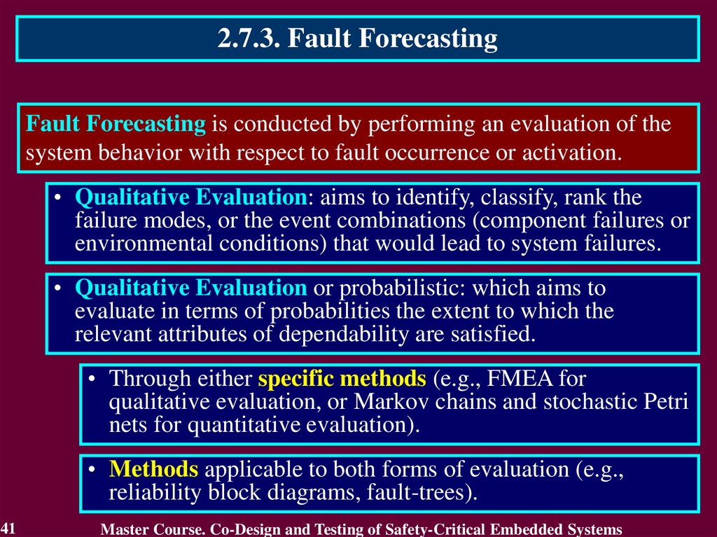
2.7.3. Fault ForecastingFault Forecasting is conducted by performing an evaluation of the
system behavior with respect to fault occurrence or activation.
• Qualitative Evaluation: aims to identify, classify, rank the
failure modes, or the event combinations (component failures or
environmental conditions) that would lead to system failures.
• Qualitative Evaluation or probabilistic: which aims to
evaluate in terms of probabilities the extent to which the
relevant attributes of dependability are satisfied.
• Through either specific methods (e.g., FMEA for
qualitative evaluation, or Markov chains and stochastic Petri
nets for quantitative evaluation).
• Methods applicable to both forms of evaluation (e.g.,
reliability block diagrams, fault-trees).
41
Master Course. Co-Design and Testing of Safety-Critical Embedded Systems
42.
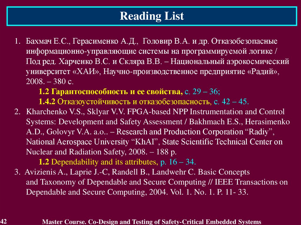
Reading List1. Бахмач Е.С., Герасименко А.Д., Головир В.А. и др. Отказобезопасные
информационно-управляющие системы на программируемой логике /
Под ред. Харченко В.С. и Скляра В.В. – Национальный аэрокосмический
университет «ХАИ», Научно-производственное предприятие «Радий»,
2008. – 380 с.
1.2 Гарантоспособность и ее свойства, с. 29 – 36;
1.4.2 Отказоустойчивость и отказобезопасность, с. 42 – 45.
2. Kharchenko V.S., Sklyar V.V. FPGA-based NPP Instrumentation and Control
Systems: Development and Safety Assessment / Bakhmach E.S., Herasimenko
A.D., Golovyr V.A. a.o.. – Research and Production Corporation “Radiy”,
National Aerospace University “KhAI”, State Scientific Technical Center on
Nuclear and Radiation Safety, 2008. – 188 p.
1.2 Dependability and its attributes, p. 16 – 34.
3. Avizienis A., Laprie J.-C, Randell B., Landwehr C. Basic Concepts
and Taxonomy of Dependable and Secure Computing // IEEE Transactions on
Dependable and Secure Computing, 2004. Vol. 1. No. 1. P. 11- 33.
42
Master Course. Co-Design and Testing of Safety-Critical Embedded Systems
43.
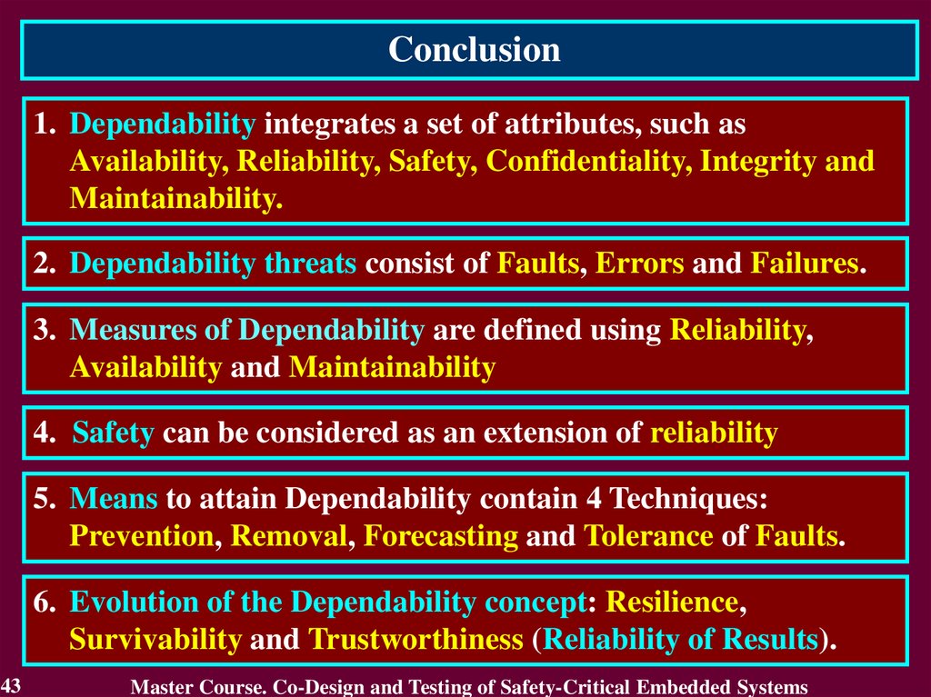
Conclusion1. Dependability integrates a set of attributes, such as
Availability, Reliability, Safety, Confidentiality, Integrity and
Maintainability.
2. Dependability threats consist of Faults, Errors and Failures.
3. Measures of Dependability are defined using Reliability,
Availability and Maintainability
4. Safety can be considered as an extension of reliability
5. Means to attain Dependability contain 4 Techniques:
Prevention, Removal, Forecasting and Tolerance of Faults.
6. Evolution of the Dependability concept: Resilience,
Survivability and Trustworthiness (Reliability of Results).
43
Master Course. Co-Design and Testing of Safety-Critical Embedded Systems
44.
Questions and tasks1.
2.
3.
4.
5.
6.
7.
8.
44
What is the Dependability?
What Dependability threats of S-CES do you know?
What kinds of faults do you know?
Define essence of Availability, Reliability, Safety,
Confidentiality, Integrity and Maintainability.
What Components of Security do you know?
What Measures of Dependability do you know?
What Techniques are contained with Means to attain
Dependability?
Define essence of Prevention, Removal, Forecasting and
Tolerance of Faults.
Master Course. Co-Design and Testing of Safety-Critical Embedded Systems
45.
MODULE 2. Dependability of S-CESand their digital components
Lecture 3. Fault Tolerance of S-CES and their
digital components
3.1. Introduction into Fault Tolerance
3.2. Error Detection
3.3. Recovery
3.4. Dependability Measures
3.5. Fault Tolerant Technologies
45
Master Course. Co-Design and Testing of Safety-Critical Embedded Systems
46.
3.1. Introduction into Fault Tolerance3.1.1. Motivation of Fault Tolerance Consideration
Fault Tolerance is a base of any S-CES and their components.
Reasons:
Fault Tolerance is the main mechanism, instrument ensuring
Dependability
Fault Tolerance ensures operative resistance to hardware and
software failures
46
Master Course. Co-Design and Testing of Safety-Critical Embedded Systems
47.
3.1.2. Related Works1. Dobson I., Randell B. Building Reliable Secure Computing Systems out of
Unreliable Insecure components // Proc. of IEEE Conference on Security and
Privacy, Oakland, USA. 1986. P. 186-193.
Authors defined “Secure-Fault Tolerance” and proposed a principle of
its realization for various types of computer systems.
2. Jean-Claude Laprie, Jean Arlat, Christian Beounes, Karama Kanoun and
Catherine Hourtolle, Hardware and Software Fault Tolerance: Denition and
Analysis of Architectural Solutions, in Proceedings FTCS 17, 1987
3. Lee P.A. and Anderson T., Fault Tolerance - Principles and Practice, second
edition, Springer Verlag/Wien, 1990
47
Master Course. Co-Design and Testing of Safety-Critical Embedded Systems
48.
3.1.3. Definition of Fault ToleranceFault Tolerance is intended to preserve the delivery of correct
service in the presence of active faults.
Fault Tolerance:
• Error Detection
• Recovery
Effectiveness of Fault Tolerance: the effectiveness of error and
fault handling mechanisms (their coverage) has a strong influence
on Dependability Measures
48
Master Course. Co-Design and Testing of Safety-Critical Embedded Systems
49.
3.2. Error DetectionError Detection defines the presence of an error.
Fault Tolerance is generally implemented by error detection and
subsequent system recovery.
Error detection originates an error signal or message within the
system. An error that is present but not detected is a latent error.
There exist two classes of error detection techniques:
• concurrent error detection, which takes place during service
delivery,
• preemptive error detection, which takes place while service
delivery is suspended; it checks the system for latent errors and
dormant faults.
49
Master Course. Co-Design and Testing of Safety-Critical Embedded Systems
50.
3.3. RecoverySystem Recovery transforms a system state that contains one
or more errors and (possibly) faults into a state without detected
errors and faults that can be activated again.
Recovery consists of
• Error Handling
• Fault Handling (Fault treatment).
50
Master Course. Co-Design and Testing of Safety-Critical Embedded Systems
51.
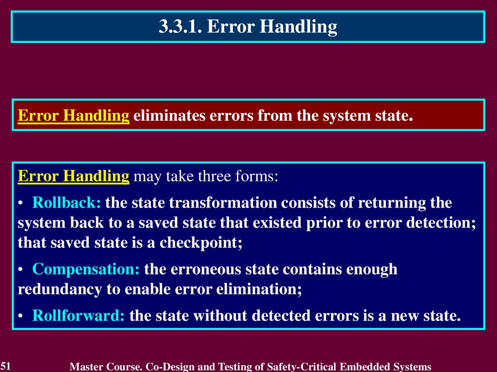
3.3.1. Error HandlingError Handling eliminates errors from the system state.
Error Handling may take three forms:
• Rollback: the state transformation consists of returning the
system back to a saved state that existed prior to error detection;
that saved state is a checkpoint;
• Compensation: the erroneous state contains enough
redundancy to enable error elimination;
• Rollforward: the state without detected errors is a new state.
51
Master Course. Co-Design and Testing of Safety-Critical Embedded Systems
52.
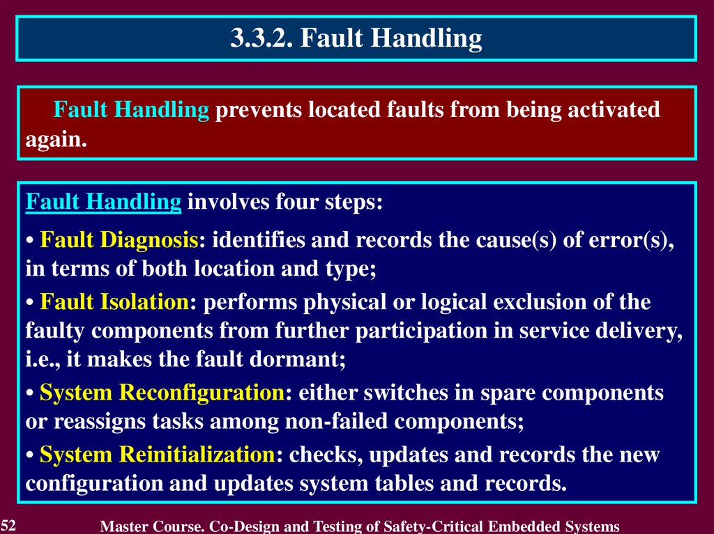
3.3.2. Fault HandlingFault Handling prevents located faults from being activated
again.
Fault Handling involves four steps:
• Fault Diagnosis: identifies and records the cause(s) of error(s),
in terms of both location and type;
• Fault Isolation: performs physical or logical exclusion of the
faulty components from further participation in service delivery,
i.e., it makes the fault dormant;
• System Reconfiguration: either switches in spare components
or reassigns tasks among non-failed components;
• System Reinitialization: checks, updates and records the new
configuration and updates system tables and records.
52
Master Course. Co-Design and Testing of Safety-Critical Embedded Systems
53.
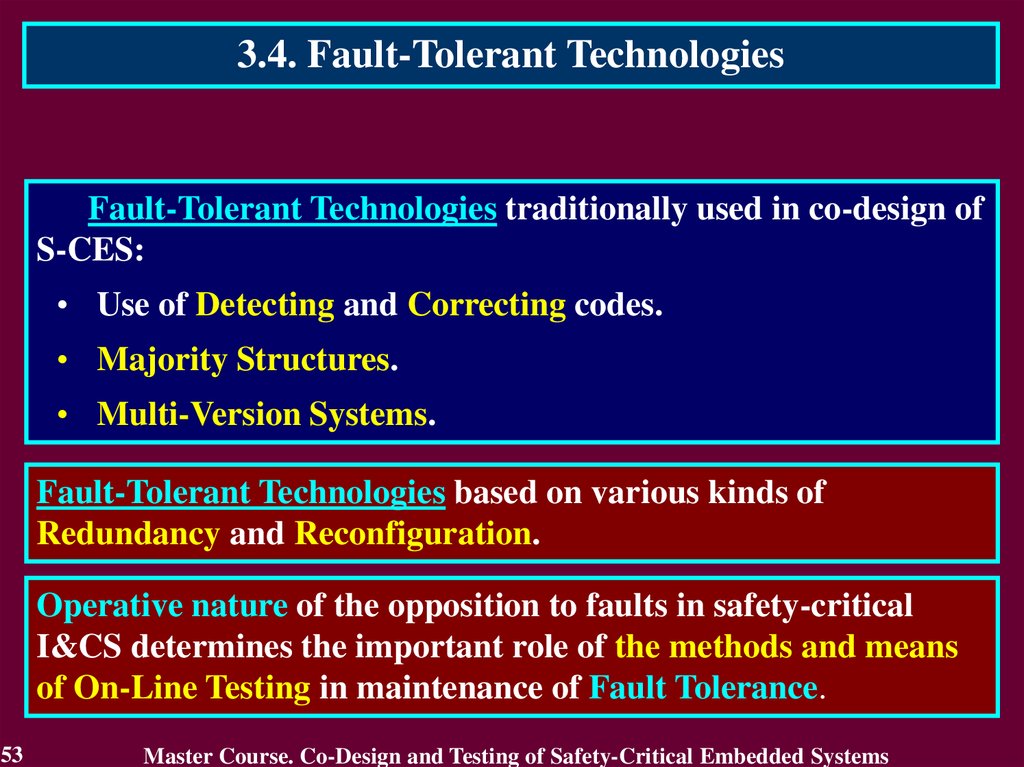
3.4. Fault-Tolerant TechnologiesFault-Tolerant Technologies traditionally used in co-design of
S-CES:
• Use of Detecting and Correcting codes.
• Majority Structures.
• Multi-Version Systems.
Fault-Tolerant Technologies based on various kinds of
Redundancy and Reconfiguration.
Operative nature of the opposition to faults in safety-critical
I&CS determines the important role of the methods and means
of On-Line Testing in maintenance of Fault Tolerance.
53
Master Course. Co-Design and Testing of Safety-Critical Embedded Systems
54.
3.4.1 Use of Detecting and Correcting codes3.4.1.1. Residue Checking for Error Detection in
arithmetic components
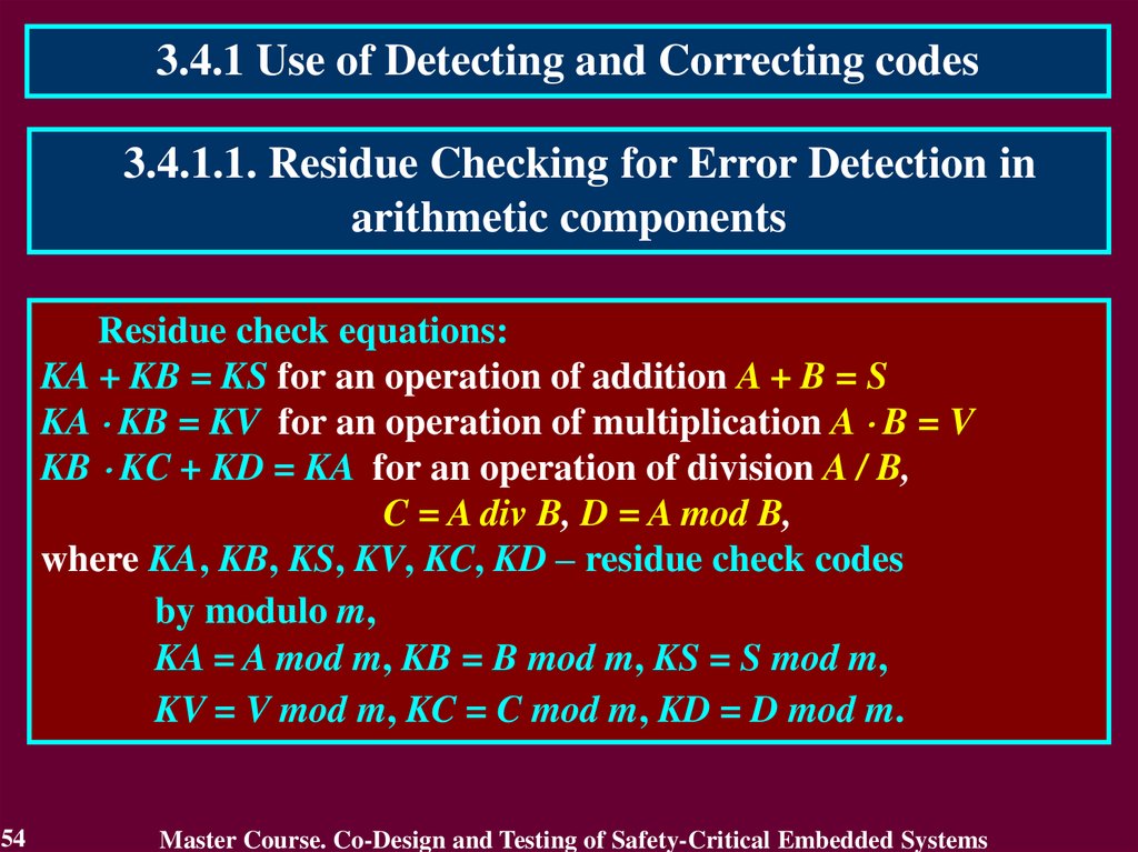
Residue check equations:
KA + KB = KS for an operation of addition A + B = S
KA KB = KV for an operation of multiplication A B = V
KB KC + KD = KA for an operation of division A / B,
C = A div B, D = A mod B,
where KA, KB, KS, KV, KC, KD – residue check codes
by modulo m,
KA = A mod m, KB = B mod m, KS = S mod m,
KV = V mod m, KC = C mod m, KD = D mod m.
54
Master Course. Co-Design and Testing of Safety-Critical Embedded Systems
55.
3.4.1.1. Residue Checking for Error Detection inarithmetic components
A{1 n}
B{1 n}
КА
КВ
R{1 nR}
DC
BCА1
EDC
KВ
BCВ 2
BCR 4
CB 3
KА
KR
КR
Blocks BCA and BCB check the operands A and B by computing the check
codes KA and KB and also comparing them with the input check codes KA
and KB. Results of comparison are the error indication codes KA and KB.
Block CB calculates the check code KR of the result R (R = S for addition
and R = V for multiplication).
Block BCR checks the result R comparing its by modulo with the check
code KR
55
Master Course. Co-Design and Testing of Safety-Critical Embedded Systems
56.
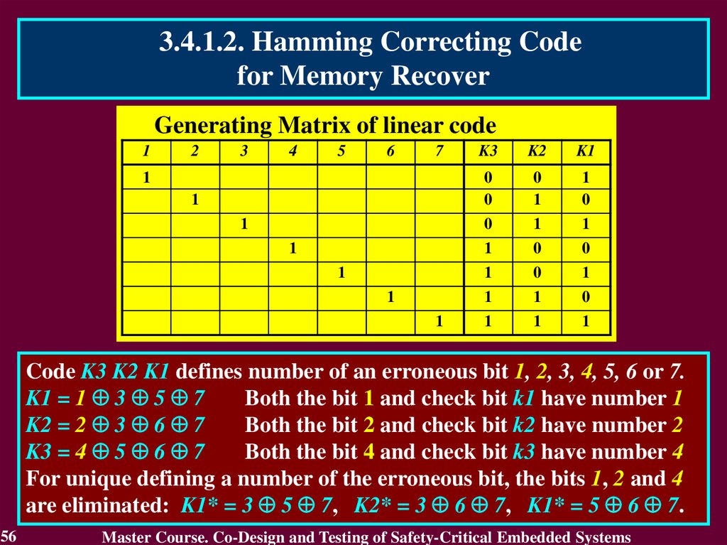
3.4.1.2. Hamming Correcting Codefor Memory Recover
Generating Matrix of linear code
1
2
3
4
5
6
7
1
1
1
1
1
1
1
K3
K2
K1
0
0
0
1
1
0
0
1
1
1
0
0
1
0
1
1
1
0
1
1
1
Code K3 K2 K1 defines number of an erroneous bit 1, 2, 3, 4, 5, 6 or 7.
K1 = 1 3 5 7
Both the bit 1 and check bit k1 have number 1
K2 = 2 3 6 7
Both the bit 2 and check bit k2 have number 2
K3 = 4 5 6 7
Both the bit 4 and check bit k3 have number 4
For unique defining a number of the erroneous bit, the bits 1, 2 and 4
are eliminated: K1* = 3 5 7, K2* = 3 6 7, K1* = 5 6 7.
56
Master Course. Co-Design and Testing of Safety-Critical Embedded Systems
57.
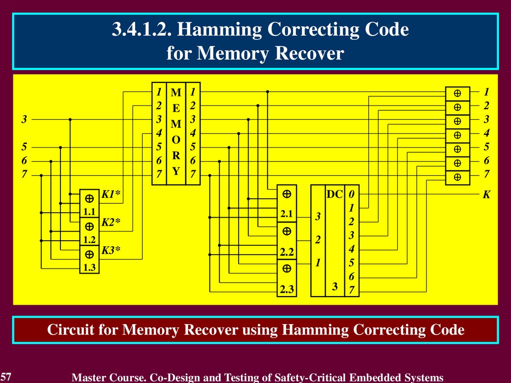
3.4.1.2. Hamming Correcting Codefor Memory Recover
1
2
3
4
5
6
7
3
5
6
7
M
E
M
O
R
Y
1
2
3
4
5
6
7
K1*
1.1
2.1
K2*
1.2
K3*
1.3
2.2
2.3
DC 0
1
3
2
3
2
4
1
5
6
3 7
Circuit for Memory Recover using Hamming Correcting Code
57
Master Course. Co-Design and Testing of Safety-Critical Embedded Systems
1
2
3
4
5
6
7
K
58.
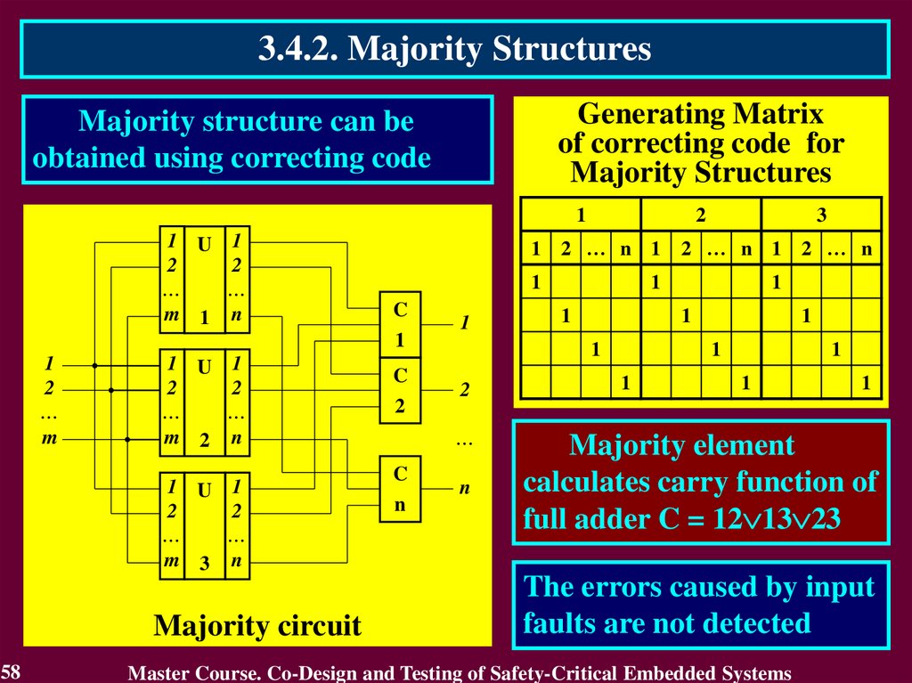
3.4.2. Majority StructuresGenerating Matrix
of correcting code for
Majority Structures
Majority structure can be
obtained using correcting code
1
1 U 1
2
2
…
…
m 1 n
1 U 1
2
2
…
…
m 2 n
1 U 1
2
2
…
…
m 3 n
Majority circuit
58
3
1 2 … n 1 2 … n 1 2 … n
1
C
1
1
2
…
m
2
C
2
1
n
1
2
n
1
1
1
…
C
1
1
1
1
1
1
1
Majority element
calculates carry function of
full adder C = 12 13 23
The errors caused by input
faults are not detected
Master Course. Co-Design and Testing of Safety-Critical Embedded Systems
59.
3.4.3. Multi-Version SystemsMulti-Version System (MVS) contains more than one version
for solving a computing task.
The version is defined as a method of system function
realization. For embedded systems it can be hardware means to
solve a computing task.
Multi-Version System are aimed to provide protection
against failure due to common reason:
• Errors of design;
• Physical Defects of Manufactory;
• Faults during Operation.
59
Master Course. Co-Design and Testing of Safety-Critical Embedded Systems
60.
3.4.3. Multi-Version SystemsMulti-Version System based on Diversity (Multi-Versity or
Version Redundancy).
Diversity means a type of redundancy based on introduction
of two or more versions.
In regulatory documents the application of Version
Redundancy goes under the name of “Principle of diversity”
Nuclear engineering uses a class of MVS including two
versions in accordance with international standards, such as:
IEC 61513:2001 ‘Nuclear power plants – Instrumentation and control
systems important to safety – General requirements for systems’
IEC 62340:2007 ‘Nuclear power plants – Instrumentation and control
systems important to safety – Requirements for coping with common cause
failure’
60
Master Course. Co-Design and Testing of Safety-Critical Embedded Systems
61.
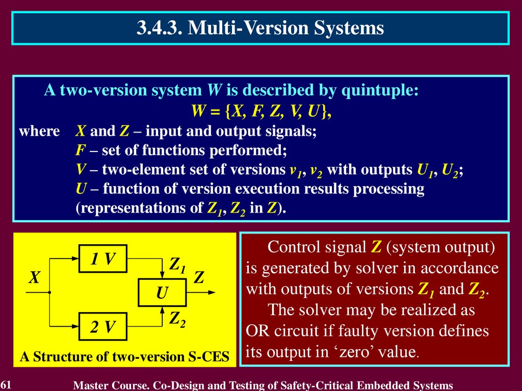
3.4.3. Multi-Version SystemsA two-version system W is described by quintuple:
W = {X, F, Z, V, U},
where X and Z – input and output signals;
F – set of functions performed;
V – two-element set of versions v1, v2 with outputs U1, U2;
U – function of version execution results processing
(representations of Z1, Z2 in Z).
Control signal Z (system output)
1V
Z1
is generated by solver in accordance
X
Z
with outputs of versions Z1 and Z2.
U
The solver may be realized as
Z2
2V
OR circuit if faulty version defines
A Structure of two-version S-CES its output in ‘zero’ value.
61
Master Course. Co-Design and Testing of Safety-Critical Embedded Systems
62.
3.4.3. Multi-Version SystemsA Classification of Diversity Types
Software diversity is the use of different programs designed and
implemented by different development groups with different
programming languages and tools to accomplish the same safety
goals.
Equipment (hardware) diversity is the use of different
equipment to perform similar safety functions in which different
means sufficiently unlike as to significantly decrease vulnerability to
common failure.
Human (life cycle) diversity is the use of different project
groups with different key personnel to accomplish the same project
goals.
62
Master Course. Co-Design and Testing of Safety-Critical Embedded Systems
63.
3.4.3. Multi-Version SystemsA Classification of Diversity Types
Design diversity is the use of different approaches including both
software and hardware, to solve the same or similar problem.
Functional diversity is the use of different physical functions
performing though they may have overlapping safety effects.
Signal diversity is the use of different sensed parameters to
initiate protective action, In which any of parameters may
independently indicate in abnormal condition, even if the other
parameters fail to be sensed correctly.
63
Master Course. Co-Design and Testing of Safety-Critical Embedded Systems
64.
3.4.3. Multi-Version SystemsDiversity types in FPGA-based S-CES
Diversity type
Diversity of
electronic elements
Way of diversity implementation
Diversity of firm developers of electronic elements
Diversity of technologies of electronic elements
producing
Diversity of electronic elements families
Diversity of electronic elements from the same family
Diversity of developers of CASE-tools
Diversity of
CASE-tools
Diversity of CASE-tools
Diversity of configuration of CASE-tools
Diversity of projects Diversity on the base of graphical language and
hardware description language
development
Diversity of hardware description languages
languages
Diversity of
Diversity of specification languages
specification
64
Master Course. Co-Design and Testing of Safety-Critical Embedded Systems
65.
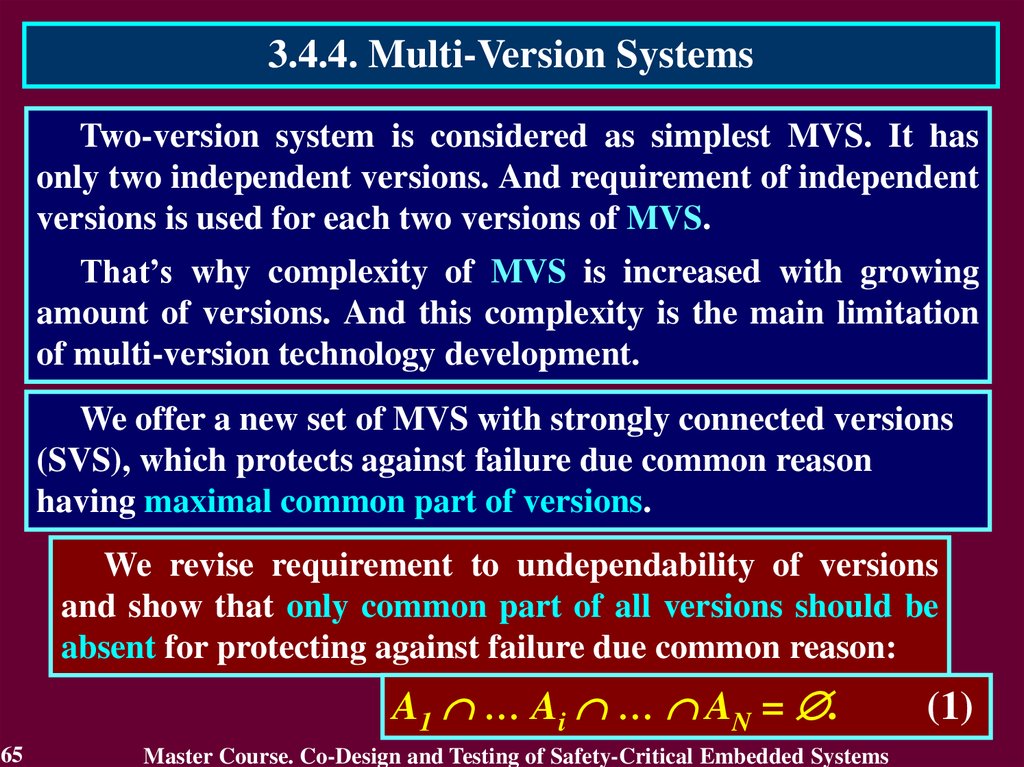
3.4.4. Multi-Version SystemsTwo-version system is considered as simplest MVS. It has
only two independent versions. And requirement of independent
versions is used for each two versions of MVS.
That’s why complexity of MVS is increased with growing
amount of versions. And this complexity is the main limitation
of multi-version technology development.
We offer a new set of MVS with strongly connected versions
(SVS), which protects against failure due common reason
having maximal common part of versions.
We revise requirement to undependability of versions
and show that only common part of all versions should be
absent for protecting against failure due common reason:
A1 … Ai … AN = .
65
Master Course. Co-Design and Testing of Safety-Critical Embedded Systems
(1)
66.
3.4.5. Computer Systems with StronglyConnected Versions
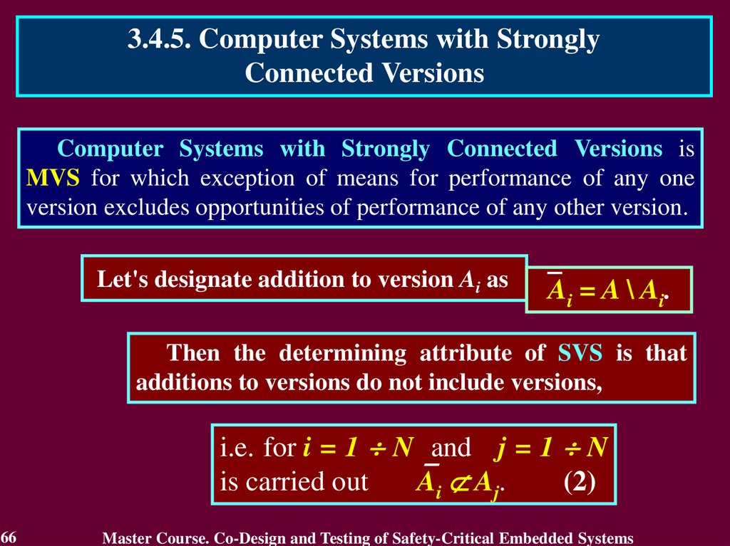
Computer Systems with Strongly Connected Versions is
MVS for which exception of means for performance of any one
version excludes opportunities of performance of any other version.
Let's designate addition to version Ai as
Ai = A \ Ai.
Then the determining attribute of SVS is that
additions to versions do not include versions,
i.e. for i = 1 N and j = 1 N
is carried out Ai Aj.
(2)
66
Master Course. Co-Design and Testing of Safety-Critical Embedded Systems
67.
3.4.5. Computer Systems with StronglyConnected Versions
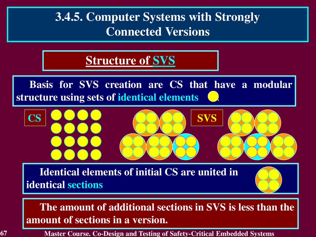
Structure of SVS
Basis for SVS creation are CS that have a modular
structure using sets of identical elements
.
CS
SVS
Identical elements of initial CS are united in
identical sections
The amount of additional sections in SVS is less than the
amount of sections in a version.
67
Master Course. Co-Design and Testing of Safety-Critical Embedded Systems
68.
3.4.5. Computer Systems with StronglyConnected Versions
Structure of SVS
A minimum quantity of
versions in a SVS is three
A maximum quantity of versions in a SVS is achieved in
case the section has one element:
CS
SVS
SVS is simplified with increase of versions quantity
68
Master Course. Co-Design and Testing of Safety-Critical Embedded Systems
69.
3.4.5. Computer Systems with StronglyConnected Versions
Protection from Failure
due to the Common Reason
The SVS becomes protected from failure due to the
common reason using two components:
• the multitude of versions, that contains at least one
true version;
• means of a choice of the true version.
69
Master Course. Co-Design and Testing of Safety-Critical Embedded Systems
70.
3.4.5. Computer Systems with StronglyConnected Versions
Complexity of SVS
Complexity of SVS
where
QIE – complexity of identical elements;
QCM – complexity of choice means.
QIE = R + R / K,
where
QCM = (K + 1) ,
R – quantity of identical elements in CS;
K – quantity of identical elements in CS;
– coefficient of proportionality.
QSVS MIN = R (1+1/K) 2,
K = R/
70
QSVS = QIE + QCM,
QDC MIN = 2R (1+1/K 2).
QDC MIN/QSVS MIN = 2(1–2K/(K+1) 2).
Master Course. Co-Design and Testing of Safety-Critical Embedded Systems
71.
3.4.5. Computer Systems with StronglyConnected Versions
Choice of the True Version
The SVS can be realized with:
• a parallel choice of the true version;
• a consecutive choice of the true version.
71
Master Course. Co-Design and Testing of Safety-Critical Embedded Systems
72.
3.4.5. Computer Systems with StronglyConnected Versions
Choice of the True Version
Choice of the true version is executed by the on-line
testing methods using means of hardware check
The version can be checked up using two approaches.
• external, i.e. check of total system;
• internal, i.e. check of each version by its own means.
The check of the version can be:
• direct, which estimates the version itself;
• indirect, which estimates its addition.
72
Master Course. Co-Design and Testing of Safety-Critical Embedded Systems
73.
3.4.5. Computer Systems with StronglyConnected Versions
Choice of the True Version
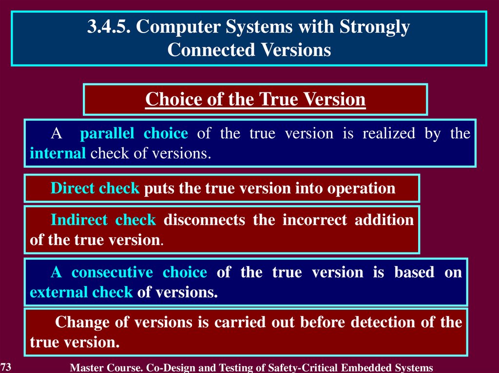
A parallel choice of the true version is realized by the
internal check of versions.
Direct check puts the true version into operation
Indirect check disconnects the incorrect addition
of the true version.
A consecutive choice of the true version is based on
external check of versions.
Change of versions is carried out before detection of the
true version.
73
Master Course. Co-Design and Testing of Safety-Critical Embedded Systems
74.
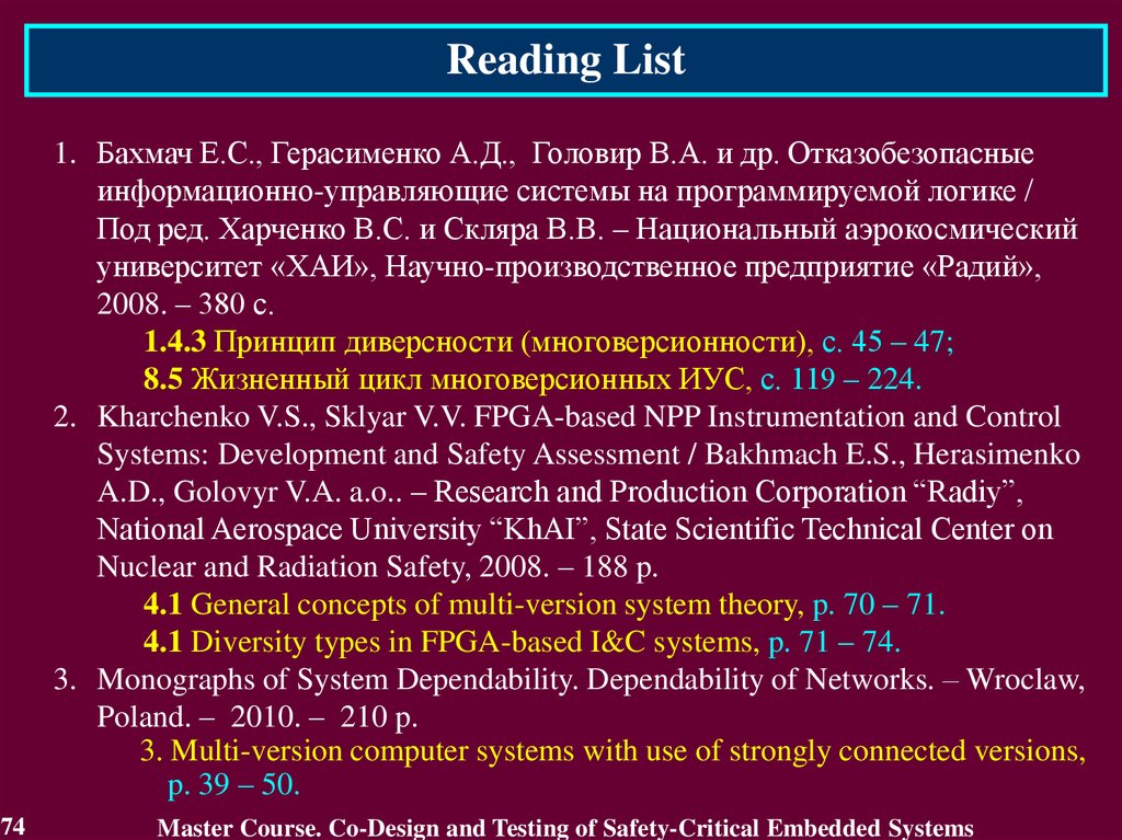
Reading List1. Бахмач Е.С., Герасименко А.Д., Головир В.А. и др. Отказобезопасные
информационно-управляющие системы на программируемой логике /
Под ред. Харченко В.С. и Скляра В.В. – Национальный аэрокосмический
университет «ХАИ», Научно-производственное предприятие «Радий»,
2008. – 380 с.
1.4.3 Принцип диверсности (многоверсионности), с. 45 – 47;
8.5 Жизненный цикл многоверсионных ИУС, с. 119 – 224.
2. Kharchenko V.S., Sklyar V.V. FPGA-based NPP Instrumentation and Control
Systems: Development and Safety Assessment / Bakhmach E.S., Herasimenko
A.D., Golovyr V.A. a.o.. – Research and Production Corporation “Radiy”,
National Aerospace University “KhAI”, State Scientific Technical Center on
Nuclear and Radiation Safety, 2008. – 188 p.
4.1 General concepts of multi-version system theory, p. 70 – 71.
4.1 Diversity types in FPGA-based I&C systems, p. 71 – 74.
3. Monographs of System Dependability. Dependability of Networks. – Wroclaw,
Poland. – 2010. – 210 p.
3. Multi-version computer systems with use of strongly connected versions,
p. 39 – 50.
74
Master Course. Co-Design and Testing of Safety-Critical Embedded Systems
75.
Conclusion1. Fault Tolerance is a base of any S-CES and their components
ensuring Dependability.
2. Fault Tolerance of S-CES is executed by Error Detection and
Recovery.
3. Recovery consists of Error Handling (rollback,
compensation, rollforward) and Fault Treatment (Fault
diagnosis and isolation, System reconfiguration and
reinitialization).
4. Fault-Tolerant Technologies based on various kinds of
Redundancy and Reconfiguration using the methods and
means of On-Line Testing.
5. Multi-Version System ensures resistance to failure due to
common reason.
6. Computer Systems with Strongly Connected Versions is
simplified with increase of versions quantity.
75
Master Course. Co-Design and Testing of Safety-Critical Embedded Systems
76.
Questions and tasks1.
2.
3.
4.
5.
6.
7.
8.
76
What is the Fault Tolerance?
What kinds of the Fault Tolerance do you know?
Recite the Error detection techniques.
What forms of Error Handling and Fault Treatment do you
know?
What property of On-Line Testing is essential for FaultTolerant Technologies?
What is it “Principle of diversity”?
What types of Diversity do you know?
Define essence of Computer Systems with Strongly
Connected Versions.
Master Course. Co-Design and Testing of Safety-Critical Embedded Systems
77.
MODULE 3.On-line testing for digital component of S-CES
#
4
5
6
7
8
77
Topic of lecture
Processing and checking
of exact data
Approximate data
processing
Reliability of on-line
testing methods
Increase of on-line testing
methods reliability
Checking by logarithm,
inequalities, segments
Total:
Lab Private
Lectures
Classes Study
2
0
2
2
0
2
2
4
4
2
2
2
2
8
2
10
14
12
Master Course. Co-Design and Testing of Safety-Critical Embedded Systems
78.
MODULE 3. On-line testingfor digital components of S-CES
Lecture 4. Processing and checking of exact data
4.1. Introduction into on-line testing
4.2. Stages of on-line testing development
4.3. Self-checking circuits
4.4. Purpose of on-line testing
4.5. Model of exact data
4.6. Processing of exact and approximate data
4.7. Component on-line testing
78
Master Course. Co-Design and Testing of Safety-Critical Embedded Systems
79.
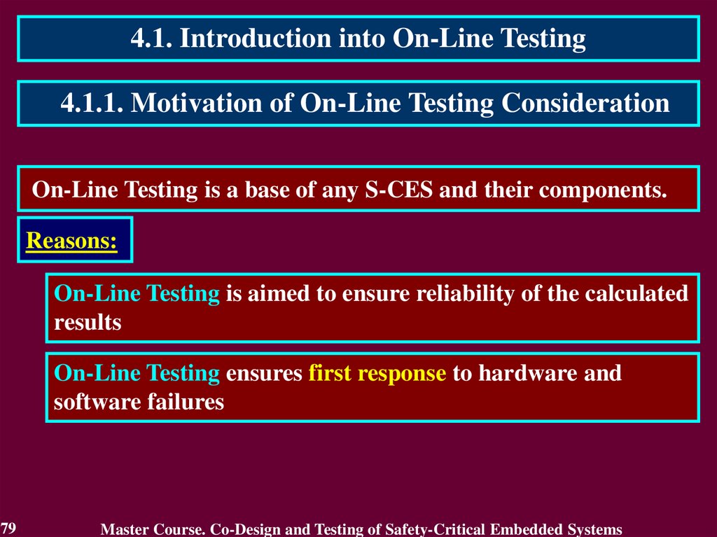
4.1. Introduction into On-Line Testing4.1.1. Motivation of On-Line Testing Consideration
On-Line Testing is a base of any S-CES and their components.
Reasons:
On-Line Testing is aimed to ensure reliability of the calculated
results
On-Line Testing ensures first response to hardware and
software failures
79
Master Course. Co-Design and Testing of Safety-Critical Embedded Systems
80.
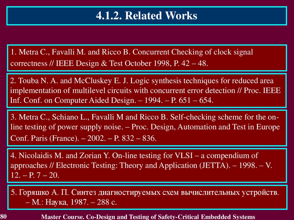
4.1.2. Related Works1. Metra C., Favalli M. and Ricco B. Concurrent Checking of clock signal
correctness // IEEE Design & Test October 1998, P. 42 – 48.
2. Touba N. A. and McCluskey E. J. Logic synthesis techniques for reduced area
implementation of multilevel circuits with concurrent error detection // Proc. IEEE
Inf. Conf. on Computer Aided Design. – 1994. – P. 651 – 654.
3. Metra C., Schiano L., Favalli M and Ricco B. Self-checking scheme for the online testing of power supply noise. – Proc. Design, Automation and Test in Europe
Conf. Paris (France). – 2002. – P. 832 – 836.
4. Nicolaidis M. and Zorian Y. On-line testing for VLSI – a compendium of
approaches // Electronic Testing: Theory and Application (JETTA). – 1998. – V.
12. – P. 7 – 20.
5. Горяшко А. П. Синтез диагностируемых схем вычислительных устройств.
– М.: Наука, 1987. – 288 c.
80
Master Course. Co-Design and Testing of Safety-Critical Embedded Systems
81.
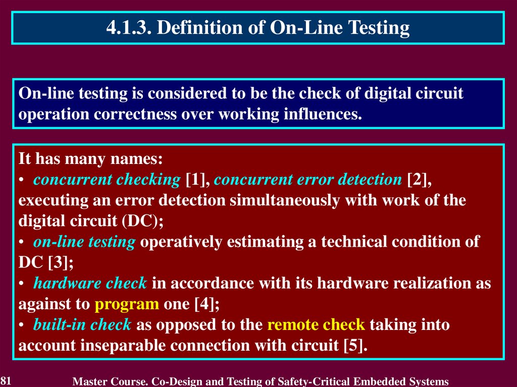
4.1.3. Definition of On-Line TestingOn-line testing is considered to be the check of digital circuit
operation correctness over working influences.
It has many names:
• concurrent checking [1], concurrent error detection [2],
executing an error detection simultaneously with work of the
digital circuit (DC);
• on-line testing operatively estimating a technical condition of
DC [3];
• hardware check in accordance with its hardware realization as
against to program one [4];
• built-in check as opposed to the remote check taking into
account inseparable connection with circuit [5].
81
Master Course. Co-Design and Testing of Safety-Critical Embedded Systems
82.
4.2. Stages of On-Line Testing DevelopmentIn development of on-line testing it is possible to select three
stages:
• the initial stage;
• stage of becoming – the development stage of self-checking
circuits which expand the on-line testing for own means
within the framework of the exact data processing;
• the present stage expanding the on-line testing for
processing of the approximate data.
82
Master Course. Co-Design and Testing of Safety-Critical Embedded Systems
83.
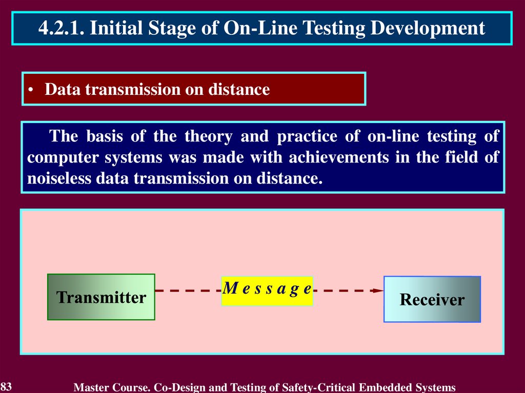
4.2.1. Initial Stage of On-Line Testing Development• Data transmission on distance
The basis of the theory and practice of on-line testing of
computer systems was made with achievements in the field of
noiseless data transmission on distance.
Message
83
Master Course. Co-Design and Testing of Safety-Critical Embedded Systems
84.
4.2.1. Initial Stage of On-Line Testing Development• Data transmission on distance
The noises on air
transmitted messages.
deformed
Noise
Message
84
Master Course. Co-Design and Testing of Safety-Critical Embedded Systems
85.
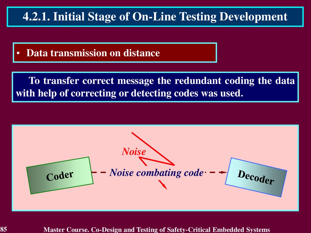
4.2.1. Initial Stage of On-Line Testing Development• Data transmission on distance
To transfer correct message the redundant coding the data
with help of correcting or detecting codes was used.
Noise
Noise combating code
85
Master Course. Co-Design and Testing of Safety-Critical Embedded Systems
86.
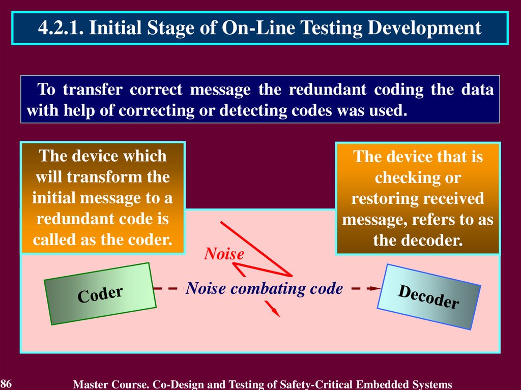
4.2.1. Initial Stage of On-Line Testing DevelopmentTo transfer correct message the redundant coding the data
with help of correcting or detecting codes was used.
The device which
will transform the
initial message to a
redundant code is
called as the coder.
Noise
The device that is
checking or
restoring received
message, refers to as
the decoder.
Noise combating code
86
Master Course. Co-Design and Testing of Safety-Critical Embedded Systems
87.
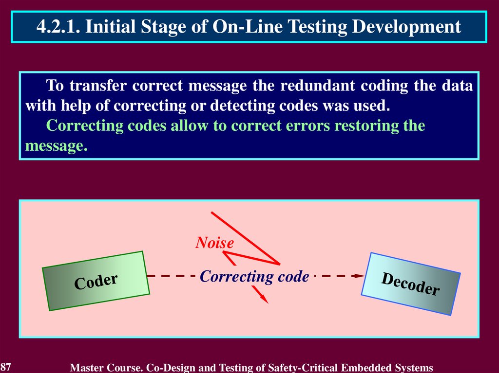
4.2.1. Initial Stage of On-Line Testing DevelopmentTo transfer correct message the redundant coding the data
with help of correcting or detecting codes was used.
Correcting codes allow to correct errors restoring the
message.
Noise
Correcting code
87
Master Course. Co-Design and Testing of Safety-Critical Embedded Systems
88.
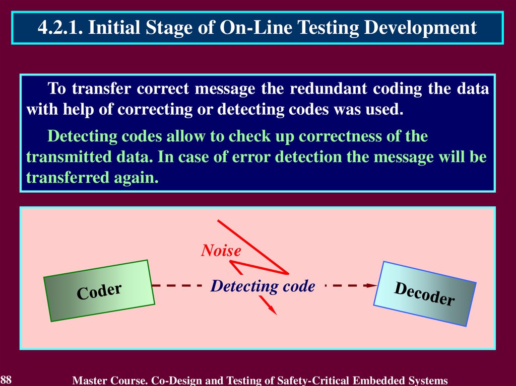
4.2.1. Initial Stage of On-Line Testing DevelopmentTo transfer correct message the redundant coding the data
with help of correcting or detecting codes was used.
Detecting codes allow to check up correctness of the
transmitted data. In case of error detection the message will be
transferred again.
Noise
Detecting code
88
Master Course. Co-Design and Testing of Safety-Critical Embedded Systems
89.
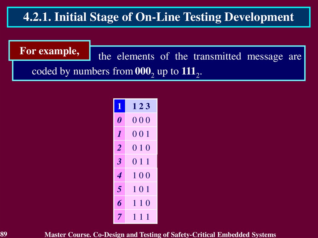
4.2.1. Initial Stage of On-Line Testing DevelopmentFor example,
the elements of the transmitted message are
coded by numbers from 0002 up to 1112.
89
1
123
0
000
1
001
2
010
3
011
4
100
5
101
6
110
7
111
Master Course. Co-Design and Testing of Safety-Critical Embedded Systems
90.
4.2.1. Initial Stage of On-Line Testing DevelopmentThe coder transforms they into words of the group code,
which can be defined by the generating array 2 with linear independent words 1, 2 and 4.
90
2
123
456
1
123
1
001
110
0
000
2
010
101
1
001
4
100
011
2
010
3
011
4
100
5
101
6
110
7
111
Master Course. Co-Design and Testing of Safety-Critical Embedded Systems
91.
4.2.1. Initial Stage of On-Line Testing DevelopmentThe decoder detects an error if it is non-code word. The code
words are checked using the linear equation that defines check bits
4, 5 and 6 as the modulo 2 sum of the information bits 1, 2 and 3.
2
123
456
1
001
2
4
3
123
456
110
0
000
000
010
101
1
001
110
100
011
2
010
101
3
011
011
4
100
011
5
101
101
6
110
110
7
111
000
For example, bit 4
is equal to the
modulo 2 sum of
the bits 2 and 3.
91
4 = 2 3
4
2 3
4
1
0 1
1
2
1 0
1
4
0 0
0
Master Course. Co-Design and Testing of Safety-Critical Embedded Systems
92.
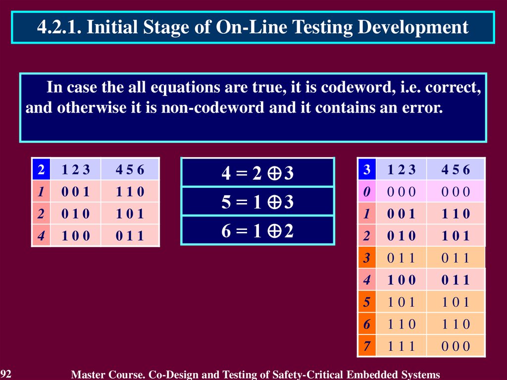
4.2.1. Initial Stage of On-Line Testing DevelopmentIn case the all equations are true, it is codeword, i.e. correct,
and otherwise it is non-codeword and it contains an error.
92
2
123
456
1
001
110
2
010
101
4
100
011
4 = 2 3
5 = 1 3
6 = 1 2
3
123
456
0
000
000
1
001
110
2
010
101
3
011
011
4
100
011
5
101
101
6
110
110
7
111
000
Master Course. Co-Design and Testing of Safety-Critical Embedded Systems
93.
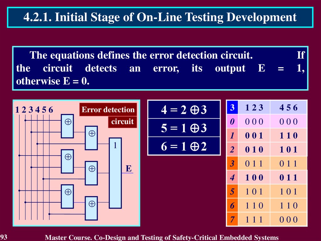
4.2.1. Initial Stage of On-Line Testing DevelopmentThe equations defines the error detection circuit.
the circuit detects an error, its output E
otherwise E = 0.
123456
Error detection
circuit
1
93
E
4 = 2 3
5 = 1 3
6 = 1 2
=
If
1,
3
123
456
0
000
000
1
001
110
2
010
101
3
011
011
4
100
011
5
101
101
6
110
110
7
111
000
Master Course. Co-Design and Testing of Safety-Critical Embedded Systems
94.
4.2.1. Initial Stage of On-Line Testing DevelopmentCoders and decoders were considered absolutely reliable
during message transfer and consequently were checked only
by test in pauses of work.
123456
Error detection
circuit
1
94
E
It has been inherited by
on-line testing, where the error
detection circuits were used
without
checking
while
operation.
Master Course. Co-Design and Testing of Safety-Critical Embedded Systems
95.
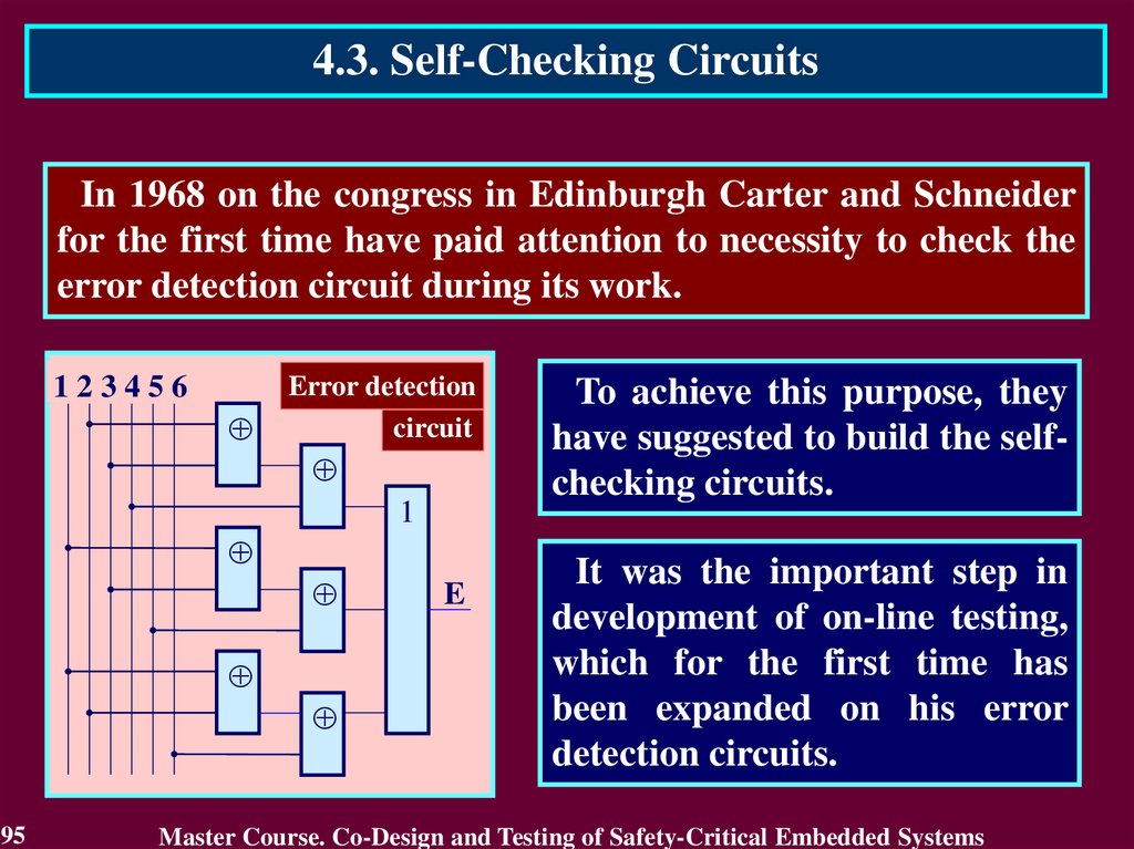
4.3. Self-Checking CircuitsIn 1968 on the congress in Edinburgh Carter and Schneider
for the first time have paid attention to necessity to check the
error detection circuit during its work.
123456
Error detection
circuit
1
95
E
To achieve this purpose, they
have suggested to build the selfchecking circuits.
It was the important step in
development of on-line testing,
which for the first time has
been expanded on his error
detection circuits.
Master Course. Co-Design and Testing of Safety-Critical Embedded Systems
96.
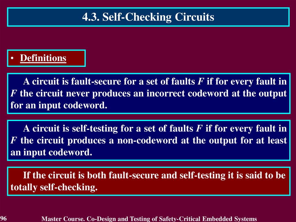
4.3. Self-Checking Circuits• Definitions
A circuit is fault-secure for a set of faults F if for every fault in
F the circuit never produces an incorrect codeword at the output
for an input codeword.
A circuit is self-testing for a set of faults F if for every fault in
F the circuit produces a non-codeword at the output for at least
an input codeword.
If the circuit is both fault-secure and self-testing it is said to be
totally self-checking.
96
Master Course. Co-Design and Testing of Safety-Critical Embedded Systems
97.
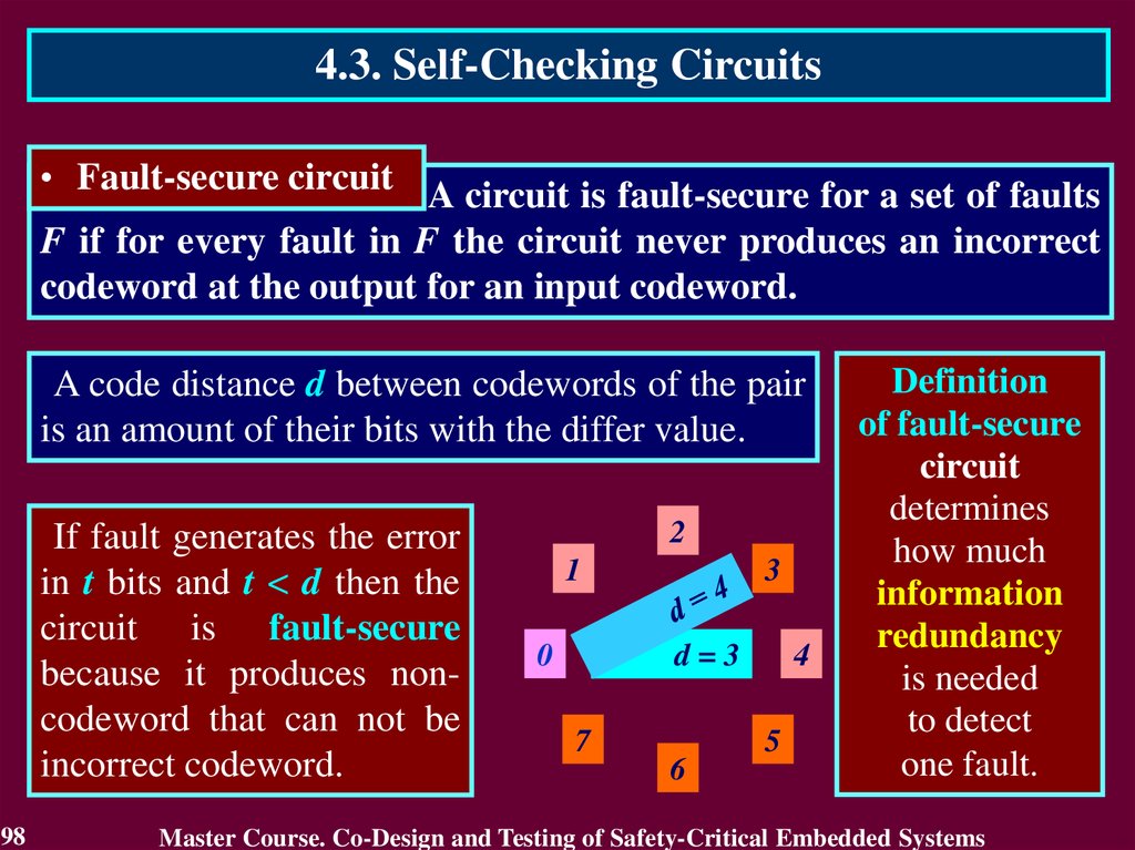
4.3. Self-Checking Circuits• Fault-secure circuit A circuit is fault-secure for a set of faults
F if for every fault in F the circuit never produces an incorrect
codeword at the output for an input codeword.
A code distance d between codewords of the pair
is an amount of their bits with the differ value.
If fault generates the error
in t bits and t < d then the
circuit is fault-secure
because it produces noncodeword that can not be
incorrect codeword.
97
2
1
0
3
d=3
7
6
4
5
3
123
456
0
000
000
1
001
110
2
010
101
3
011
011
4
100
011
5
101
101
6
110
110
7
111
000
Master Course. Co-Design and Testing of Safety-Critical Embedded Systems
98.
4.3. Self-Checking Circuits• Fault-secure circuit A circuit is fault-secure for a set of faults
F if for every fault in F the circuit never produces an incorrect
codeword at the output for an input codeword.
A code distance d between codewords of the pair
is an amount of their bits with the differ value.
If fault generates the error
in t bits and t < d then the
circuit is fault-secure
because it produces noncodeword that can not be
incorrect codeword.
98
2
1
0
3
d=3
7
6
4
5
Definition
of fault-secure
circuit
determines
how much
information
redundancy
is needed
to detect
one fault.
Master Course. Co-Design and Testing of Safety-Critical Embedded Systems
99.
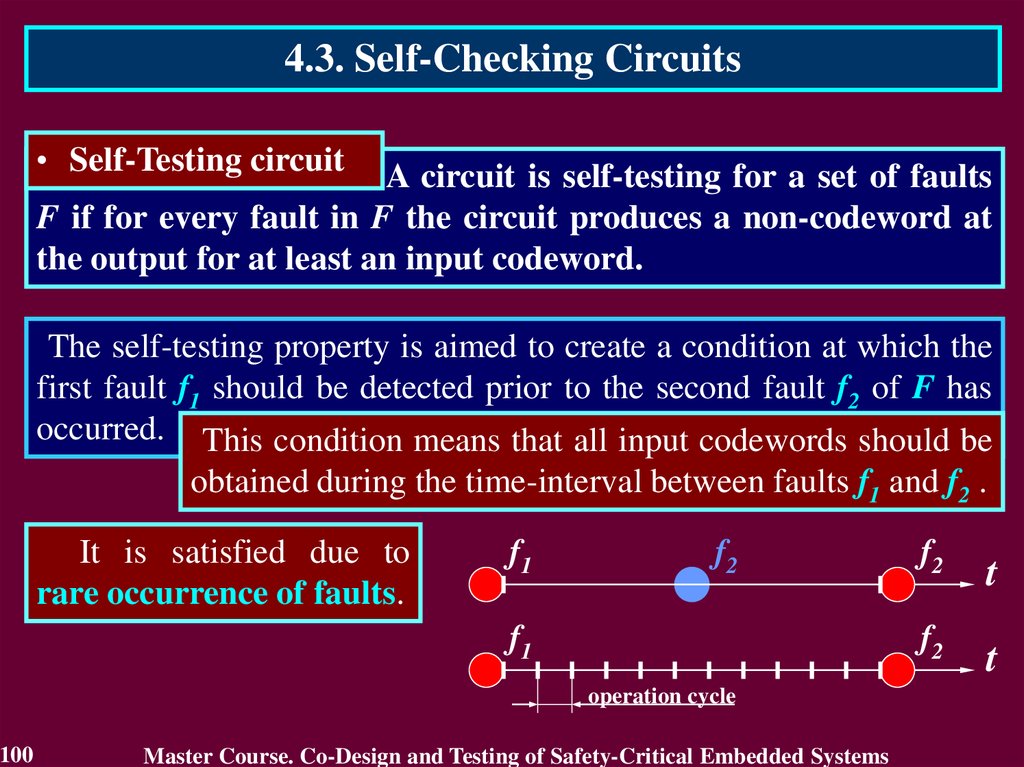
4.3. Self-Checking Circuits• Self-Testing circuit
A circuit is self-testing for a set of faults
F if for every fault in F the circuit produces a non-codeword at
the output for at least an input codeword.
The self-testing property is aimed to create a condition at which the
first fault f1 should be detected prior to the second fault f2 of F has
occurred. This condition means that all input codewords should be
obtained during the time-interval between faults f1 and f2 .
It is satisfied due to
rare occurrence of faults.
f1
f2
t
f1
f2
t
operation cycle
99
Master Course. Co-Design and Testing of Safety-Critical Embedded Systems
100.
4.3. Self-Checking Circuits• Self-Testing circuit
A circuit is self-testing for a set of faults
F if for every fault in F the circuit produces a non-codeword at
the output for at least an input codeword.
The self-testing property is aimed to create a condition at which the
first fault f1 should be detected prior to the second fault f2 of F has
occurred. This condition means that all input codewords should be
obtained during the time-interval between faults f1 and f2 .
It is satisfied due to
rare occurrence of faults.
f1
f2
f1
operation cycle
100
Master Course. Co-Design and Testing of Safety-Critical Embedded Systems
f2
t
f2
t
101.
4.3. Self-Checking Circuits• Self-Testing circuit
A circuit is self-testing for a set of faults
F if for every fault in F the circuit produces a non-codeword at
the output for at least an input codeword.
The self-testing property is aimed to create a condition at which the
first fault f1 should be detected prior to the second fault f2 of F has
occurred. This condition means that all input codewords should be
obtained during the time-interval between faults f1 and f2 .
It is satisfied due to rare
occurrence of faults and
high-frequency operations
of the computing circuits.
101
f1
f2
f1
operation cycle
Master Course. Co-Design and Testing of Safety-Critical Embedded Systems
f2
t
f2
t
102.
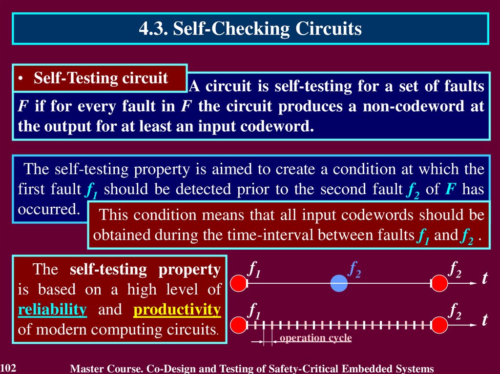
4.3. Self-Checking Circuits• Self-Testing circuit
A circuit is self-testing for a set of faults
F if for every fault in F the circuit produces a non-codeword at
the output for at least an input codeword.
The self-testing property is aimed to create a condition at which the
first fault f1 should be detected prior to the second fault f2 of F has
occurred. This condition means that all input codewords should be
obtained during the time-interval between faults f1 and f2 .
The self-testing property
is based on a high level of
reliability and productivity
of modern computing circuits.
102
f1
f2
f1
operation cycle
Master Course. Co-Design and Testing of Safety-Critical Embedded Systems
f2
t
f2
t
103.
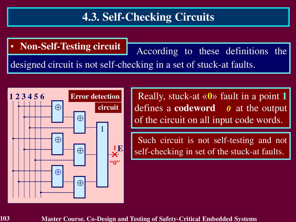
4.3. Self-Checking Circuits• Non-Self-Testing circuit
According to these definitions the
designed circuit is not self-checking in a set of stuck-at faults.
123456
Error detection
circuit
Really, stuck-at «0» fault in a point 1
defines a codeword 0 at the output
of the circuit on all input code words.
1
1E
Such circuit is not self-testing and not
self-checking in set of the stuck-at faults.
“0”
103
Master Course. Co-Design and Testing of Safety-Critical Embedded Systems
104.
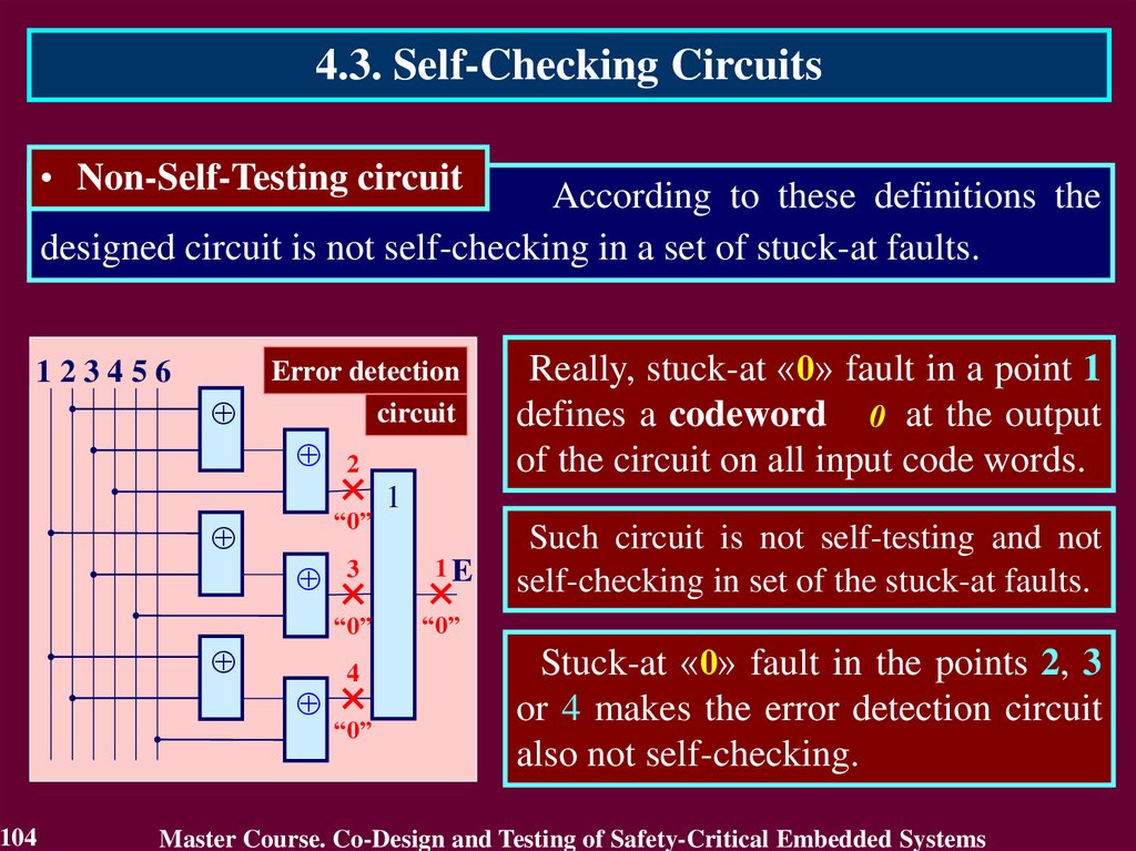
4.3. Self-Checking Circuits• Non-Self-Testing circuit
According to these definitions the
designed circuit is not self-checking in a set of stuck-at faults.
123456
Error detection
circuit
2
“0”
3
“0”
104
4
“0”
Really, stuck-at «0» fault in a point 1
defines a codeword 0 at the output
of the circuit on all input code words.
1
1E
Such circuit is not self-testing and not
self-checking in set of the stuck-at faults.
“0”
Stuck-at «0» fault in the points 2, 3
or 4 makes the error detection circuit
also not self-checking.
Master Course. Co-Design and Testing of Safety-Critical Embedded Systems
105.
4.3. Self-Checking Circuits• Design of Self-Checking circuit In order to design self-checking
circuit the bits 4, 5 and 6 are complemented with their inverse bits 4,
5 and 6.
123456
Error detection
circuit
3
“0”
105
2
“0”
123456
4
“0”
1
1E
“0”
4
4
5
5
6
6
Master Course. Co-Design and Testing of Safety-Critical Embedded Systems
106.
4.3. Self-Checking CircuitsSELF-CHECKING
CIRCUITS
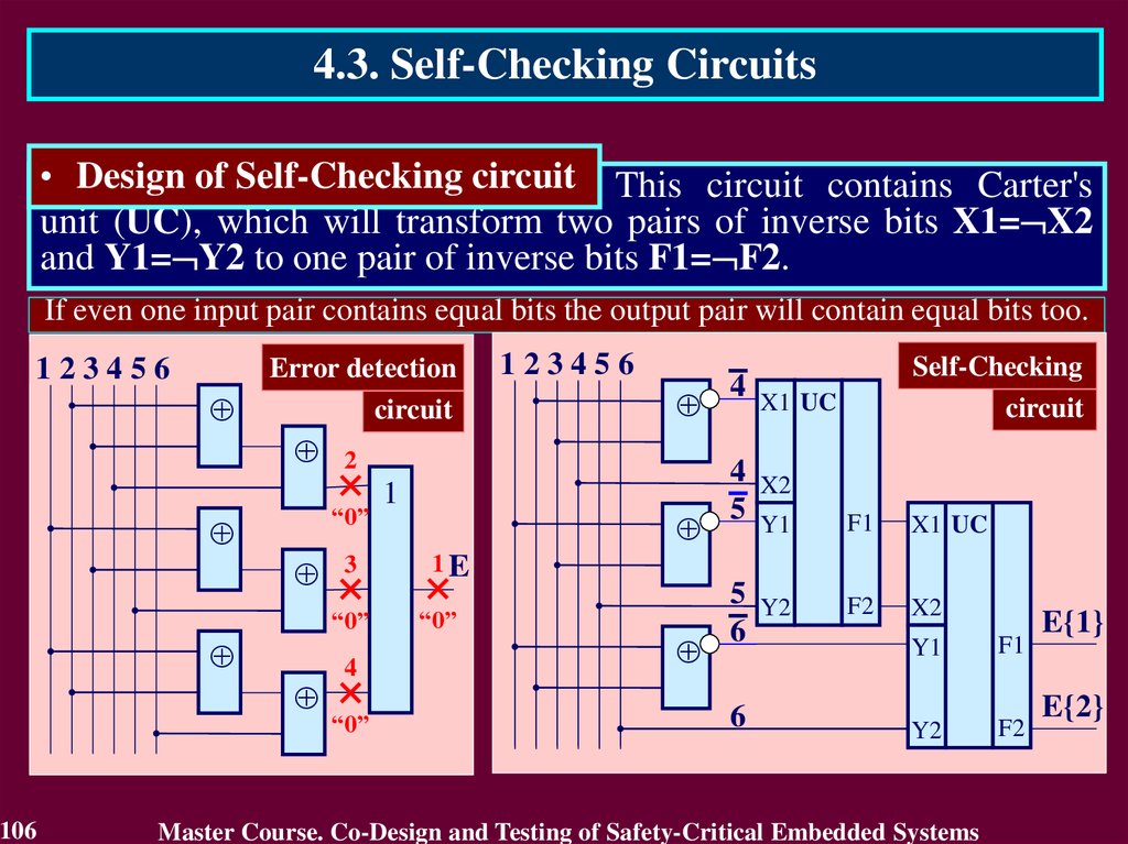
• Design of Self-Checking circuit This circuit contains Carter's
unit (UC), which will transform two pairs of inverse bits X1= X2
and Y1= Y2 to one pair of inverse bits F1= F2.
If even one input pair contains equal bits the output pair will contain equal bits too.
123456
Error detection
circuit
3
“0”
106
2
“0”
123456
4
“0”
1
1E
“0”
4
Self-Checking
circuit
X1 UC
4
5
X2
Y1
F1
X1 UC
5
6
Y2
F2
X2
6
Y1
F1
Y2
F2
Master Course. Co-Design and Testing of Safety-Critical Embedded Systems
E{1}
E{2}
107.
4.3. Self-Checking CircuitsSELF-CHECKING
CIRCUITS
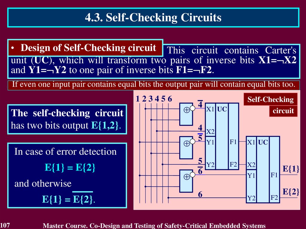
• Design of Self-Checking circuit This circuit contains Carter's
unit (UC), which will transform two pairs of inverse bits X1= X2
and Y1= Y2 to one pair of inverse bits F1= F2.
If even one input pair contains equal bits the output pair will contain equal bits too.
123456
The self-checking circuit
has two bits output E{1,2}.
In case of error detection
E{1} = E{2}
and otherwise
E{1} = E{2}.
107
4
Self-Checking
circuit
X1 UC
4
5
X2
Y1
F1
X1 UC
5
6
Y2
F2
X2
6
Y1
F1
Y2
F2
Master Course. Co-Design and Testing of Safety-Critical Embedded Systems
E{1}
E{2}
108.
4.3. Self-Checking Circuits• Design of Self-Checking circuit
The next decades on-line testing has received wide
development in a part of the self-checking circuit.
Using parity, residue and other methods of checking, the selfchecking circuits were designed:
• self-checking combinational circuits;
• self-checking asynchronous and synchronous sequential
machines;
• self-checking Adders and ALUS, Multiply and Divide Arrays.
108
Master Course. Co-Design and Testing of Safety-Critical Embedded Systems
109.
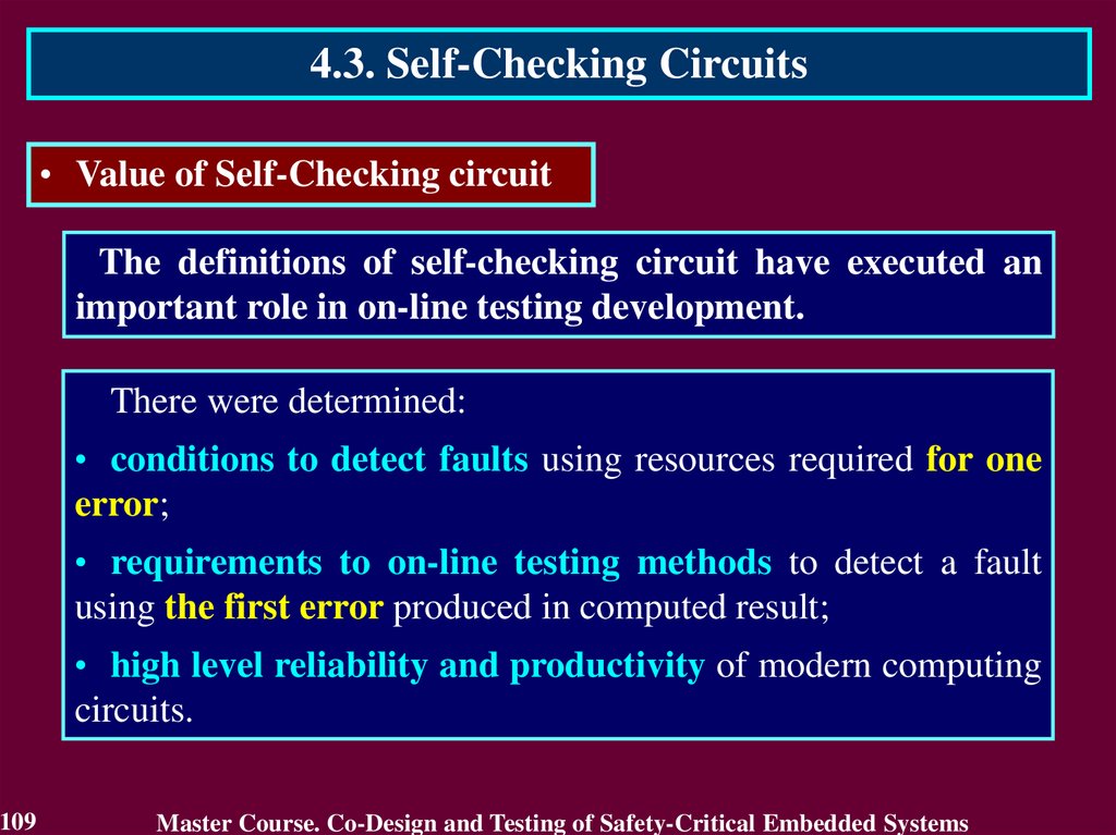
4.3. Self-Checking Circuits• Value of Self-Checking circuit
The definitions of self-checking circuit have executed an
important role in on-line testing development.
There were determined:
• conditions to detect faults using resources required for one
error;
• requirements to on-line testing methods to detect a fault
using the first error produced in computed result;
• high level reliability and productivity of modern computing
circuits.
109
Master Course. Co-Design and Testing of Safety-Critical Embedded Systems
110.
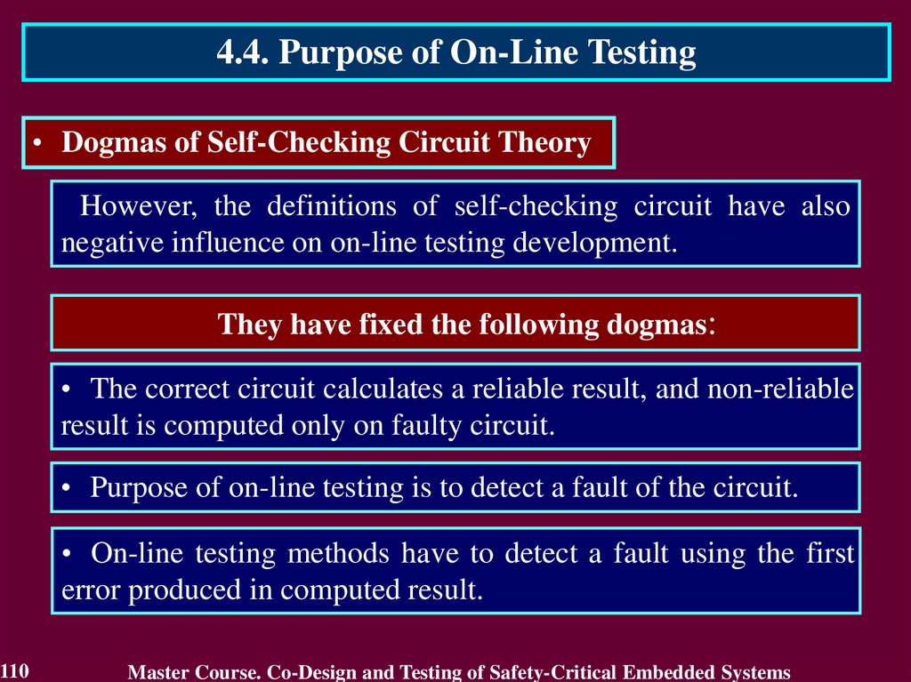
4.4. Purpose of On-Line Testing• Dogmas of Self-Checking Circuit Theory
However, the definitions of self-checking circuit have also
negative influence on on-line testing development.
They have fixed the following dogmas:
• The correct circuit calculates a reliable result, and non-reliable
result is computed only on faulty circuit.
• Purpose of on-line testing is to detect a fault of the circuit.
• On-line testing methods have to detect a fault using the first
error produced in computed result.
110
Master Course. Co-Design and Testing of Safety-Critical Embedded Systems
111.
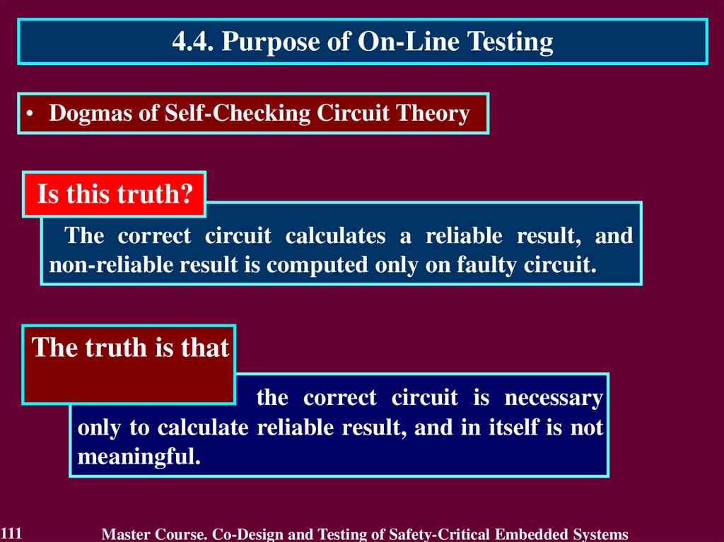
4.4. Purpose of On-Line Testing• Dogmas of Self-Checking Circuit Theory
Is this truth?
The correct circuit calculates a reliable result, and
non-reliable result is computed only on faulty circuit.
The truth is that
the correct circuit is necessary
only to calculate reliable result, and in itself is not
meaningful.
111
Master Course. Co-Design and Testing of Safety-Critical Embedded Systems
112.
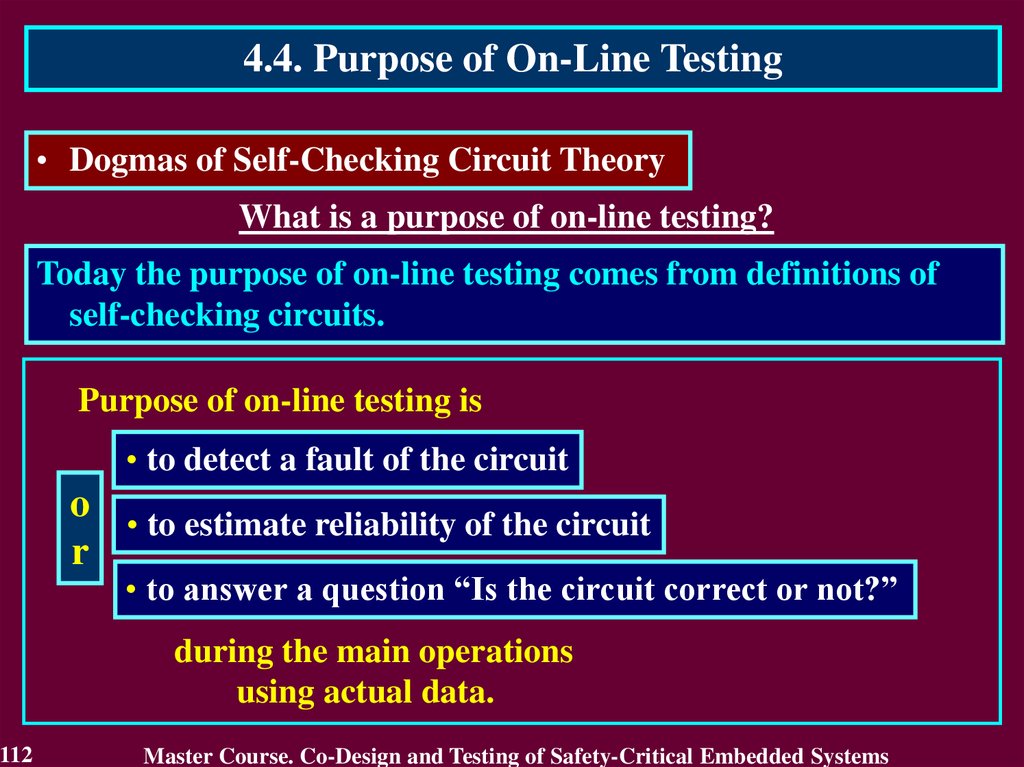
4.4. Purpose of On-Line Testing• Dogmas of Self-Checking Circuit Theory
What is a purpose of on-line testing?
Today the purpose of on-line testing comes from definitions of
self-checking circuits.
Purpose of on-line testing is
• to detect a fault of the circuit
o • to estimate reliability of the circuit
r
• to answer a question “Is the circuit correct or not?”
during the main operations
using actual data.
112
Master Course. Co-Design and Testing of Safety-Critical Embedded Systems
113.
4.4. Purpose of On-Line Testing• Dogmas of Self-Checking Circuit Theory
What is a purpose of on-line testing?
Today the purpose of on-line testing comes from definitions of
self-checking circuits.
This presentation will show that declared purpose
• defies common sense
a
n • contradicts actual on-line testing application
d
• is not achievable for self-checking circuits
during the main operations
using actual data.
113
Master Course. Co-Design and Testing of Safety-Critical Embedded Systems
114.
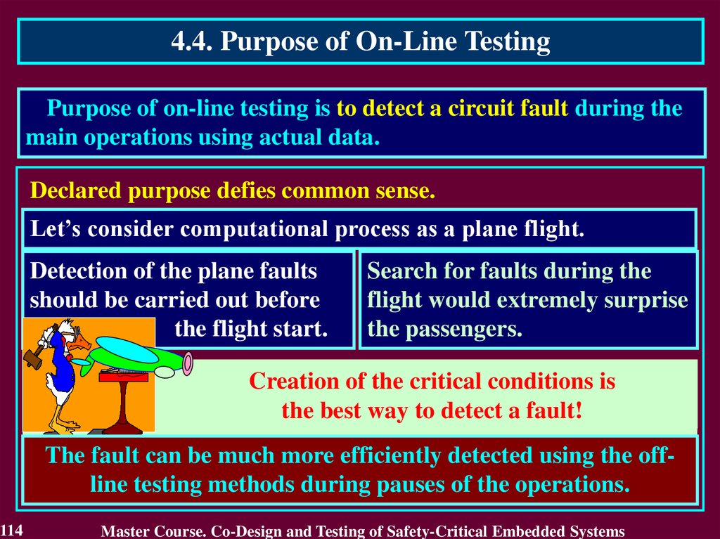
4.4. Purpose of On-Line TestingPurpose of on-line testing is to detect a circuit fault during the
main operations using actual data.
Declared purpose defies common sense.
Let’s consider computational process as a plane flight.
Detection of the plane faults
should be carried out before
the flight start.
Search for faults during the
flight would extremely surprise
the passengers.
Creation
Creationof
of the
the critical
critical conditions
conditionsisis
thebest
best way
way to detect
the
detectaafault!
fault!
The fault can be much more efficiently detected using the offline testing methods during pauses of the operations.
114
Master Course. Co-Design and Testing of Safety-Critical Embedded Systems
115.
4.4. Purpose of On-Line TestingPurpose of on-line testing is to detect a circuit fault during the
main operations using actual data.
Declared purpose defies common sense.
Faulty circuit can be considered as a mine field.
Circuit fault is a mine.
Test input words are minesweepers that
detect mines before the main operations.
Actual data is a farmer working in the field.
Search of faults during computations defies common sense as
detection of mines using farmers (actual data).
115
Master Course. Co-Design and Testing of Safety-Critical Embedded Systems
116.
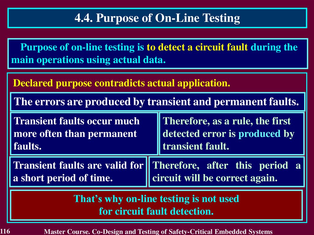
4.4. Purpose of On-Line TestingPurpose of on-line testing is to detect a circuit fault during the
main operations using actual data.
Declared purpose contradicts actual application.
The errors are produced by transient and permanent faults.
Transient faults occur much
more often than permanent
faults.
Therefore, as a rule, the first
detected error is produced by
transient fault.
Transient faults are valid for Therefore, after this period a
a short period of time.
circuit will be correct again.
That’s why on-line testing is not used
for circuit fault detection.
116
Master Course. Co-Design and Testing of Safety-Critical Embedded Systems
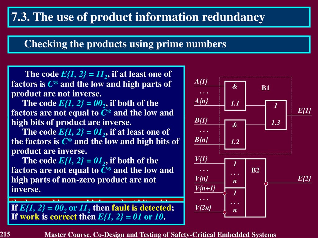
117.
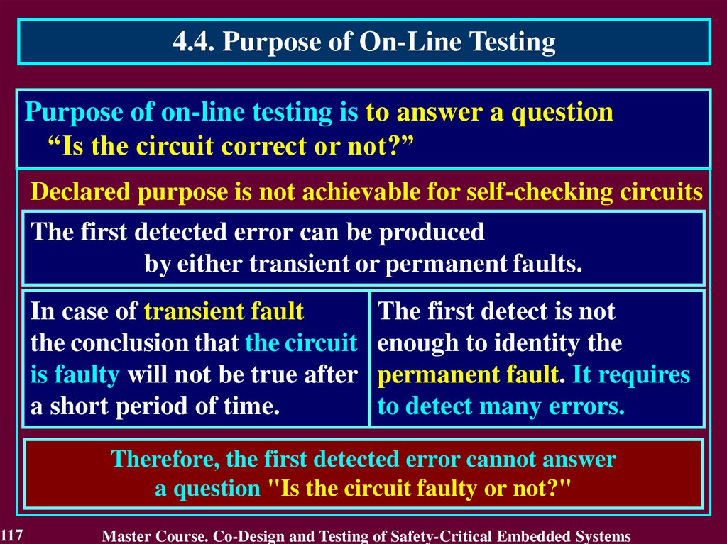
4.4. Purpose of On-Line TestingPurpose of on-line testing is to answer a question
“Is the circuit correct or not?”
Declared purpose is not achievable for self-checking circuits
The first detected error can be produced
by either transient or permanent faults.
In case of transient fault
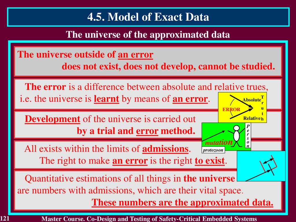
the conclusion that the circuit
is faulty will not be true after
a short period of time.
The first detect is not
enough to identity the
permanent fault. It requires
to detect many errors.
Therefore, the first detected error cannot answer
a question "Is the circuit faulty or not?"
117
Master Course. Co-Design and Testing of Safety-Critical Embedded Systems
118.
4.4. Purpose of On-Line TestingActual purpose of on-line testing can be derived from the
practice of its application.
Actual purpose of on-line testing is
• to detect an error, which reduces reliability
of the calculated result
o
• to estimate reliability of the calculated result
r
• to answer a question “Is the result reliable or not?”
during the main operations using actual data.
The correct circuit is only necessary to get a reliable result from
actual data. That is why reliability of the circuit by itself should
not be the subject of estimation during the main operations.
118
Master Course. Co-Design and Testing of Safety-Critical Embedded Systems
119.
4.4. Purpose of On-Line Testing• Declared vs. Actual purpose
Declared purpose
Actual purpose
is to estimate
reliability of a circuit
is to estimate
reliability of a result
The result
is checked
to answer
a question “Is
a circuit
correct or
faulty”
119
PURPOSE
Means to achieve purpose
Correct circuit
is
only
required to get
a reliable result
from actual
data
Master Course. Co-Design and Testing of Safety-Critical Embedded Systems
120.
4.5. Model of Exact Data• What is the reason to declare incorrect purpose?
This reason is the Model of Exact Data
This model means that
all numbers
irrespectively of their true nature
are considered as
exact data.
120
Master Course. Co-Design and Testing of Safety-Critical Embedded Systems
121.
4.5. Model of Exact DataThe universe of the approximated data
The universe outside of an error
does not exist, does not develop, cannot be studied.
The error is a difference between absolute and relative trues,
T
Absolute
i.e. the universe is learnt by means of an error.
r
ERROR
Development of the universe is carried out
by a trial and error method.
mutation
All exists within the limits of admissions. protozoon
The right to make an error is the right to exist.
u
t
Relative h
P
e
r
s
o
n
Quantitative estimations of all things in the universe
are numbers with admissions, which are their vital space.
These numbers are the approximated data.
121
Master Course. Co-Design and Testing of Safety-Critical Embedded Systems
122.
4.5. Model of Exact Data• What is Exact Data?
The Exact Data enumerates elements of a set, i.e., it
includes only “integers by nature”.
All values of codeword can be mapped to the respective
ordinal numbers. They are integers by nature and belong to
Exact Data. Everything that can be written down in a field of a
computer format is the exact data as well as it can be
numbered.
For example, 4-bits codeword has the following values and
their ordinal numbers:
0 0 10 10
122
3210
Master Course. Co-Design and Testing of Safety-Critical Embedded Systems
123.
4.5. Model of Exact DataThe exact data model means that all numbers
irrespectively of their true nature
are considered as exact data.
Many concepts
first of all connected to a computer,
are under influence of model of the exact data
123
Master Course. Co-Design and Testing of Safety-Critical Embedded Systems
124.
4.5. Model of Exact Data• On-line testing is based on the Model of Exact Data
Nobody declared this model
but it is a foundation for
• self-checking circuit techniques to obtain reliable results on
correct circuit only;
This logic is based on assumption that
the correct circuit calculates a reliable result always,
and non-reliable result is received only on faulty circuit.
It is true only
in case of exact data.
124
Master Course. Co-Design and Testing of Safety-Critical Embedded Systems
125.
4.5. Model of Exact Data• On-line testing is based on the Model of Exact Data
Nobody declared this model
but it is a foundation for
• the declared on-line testing purpose to estimate reliability of a
circuit through detection of its fault;
All errors are essential for reliability of an exact result.
A detected error concurrently shows that the calculated result
is non-reliable and the circuit has a fault.
This identifies the declared and actual purposes
for the case of exact data.
125
Master Course. Co-Design and Testing of Safety-Critical Embedded Systems
126.
4.5. Model of Exact Data• On-line testing is based on the Model of Exact Data
Nobody declared this model
but it is a foundation for
• the main requirement to on-line testing methods: detect
the first error produced by the circuit fault;
Every error in exact result makes it non-reliable and the
computing task terminates abnormally.
The first error detection allows to recalculate this result as
soon as it is possible in case of exact data.
The first error detection is the fastest way to receive
reliable results in case of exact data.
126
Master Course. Co-Design and Testing of Safety-Critical Embedded Systems
127.
4.5. Model of Exact Data• On-line testing is based on the Model of Exact Data
Nobody declared this model
but it is a foundation for
• self-checking circuit techniques to obtain reliable results on
correct circuit only;
• the declared on-line testing purpose to estimate reliability of
a circuit through detection of its fault;
• the main requirement to on-line testing methods: detect
the first error produced by the circuit fault;
• the on-line testing development within the framework of
the exact data processing only.
127
Master Course. Co-Design and Testing of Safety-Critical Embedded Systems
128.
Reading List1.
2.
3.
4.
5.
6.
128
Дрозд А. Этапы развития рабочего диагностирования вычислительных
устройств / А. Дрозд // Компьютерные науки и технологии. – Варна
(Болгария), 2009. – № 1. – С. 44 – 50.
Пархоменко П. П., Согомонян Е. С. и др. Основы технической
диагностики. – М.: Энергия, 1981. – 320 c.
Согомонян Е. С., Слабаков Е. В. Самопроверяемые вычислительные
устройства и системы (обзор) // Автоматика и телемеханика. – 1981. – №
11. – С. 147 – 167.
Согомонян Е. С., Слабаков Е. В. Самопроверяемые устройства и
отказоустойчивые системы. – М.: Радио и связь, 1989. – 208 с.
Дрозд А.В. Нетрадиционный взгляд на рабочее диагностирование
вычислительных устройств // Проблемы управления. – 2008. – № 2. – С.
48 – 56. с.
Дрозд А.В. Нетрадиционный взгляд на рабочее диагностирование
вычислительных устройств / А.В. Дрозд // Автоматизированные системы
управления и приборы автоматики. – 2009. – Вып. 147. – С. 15 – 24.
Master Course. Co-Design and Testing of Safety-Critical Embedded Systems
129.
Conclusion1. On-line testing is a base of any S-CES and their components
ensuring reliability of calculated results.
2. In development of on-line testing it is possible to select three
stages: the initial stage, stage of becoming – self-checking
circuits development expanding the on-line testing for own
means within the framework of the exact data processing,
the present stage of on-line testing development for processing
of the approximate data.
3. Totally self-checking circuits detect the faults using the first
error of the calculated results
4. Self-checking circuits theory defines a purpose of on-line
testing as estimation of the circuit reliability, however the
actual purpose is checking the result reliability.
5. Model of exact data defines development of on-line testing
within the framework of the exact data processing
129
Master Course. Co-Design and Testing of Safety-Critical Embedded Systems
130.
Questions and tasks1.
2.
3.
4.
5.
6.
What names of on-line testing do you know?
Recite the stages of on-line testing.
Describe the initial stage of on-line testing development.
What conditions of self-checking circuits do you know?
What does fault security and self-testing mean?
What purpose of on-line testing follows from definitions of a
self-checking circuit?
7. What is actual purpose of on-line testing?
8. What is Exact Data?
9. What is the Model of Exact Data?
10. Describe the role which the Model of Exact Data plays in online testing development.
130
Master Course. Co-Design and Testing of Safety-Critical Embedded Systems
131.
MODULE 3. On-line testingfor digital components of S-CES
Lecture 5. Approximate Data Processing
5.1. Introduction into Approximate Data Processing
5.2. Floating-point Formats and Arithmetic
5.3. Complete and Truncated Operations
5.4. Features of Approximate Data Processing
5.5. Probability of an essential error
131
Master Course. Co-Design and Testing of Safety-Critical Embedded Systems
132.
5.1. Introduction into Approximate Data Processing5.1.1. Motivation of Approximate Data Processing
Consideration
The majority of processed numbers is approximate data and
their volume only increase.
Reasons:
Our Universe is approximate and all in it are structured
under its realities including computer Processing
That’s why Universe generates approximate data
132
Master Course. Co-Design and Testing of Safety-Critical Embedded Systems
133.
5.1.2. Related Works1. Гук М. Процессоры Intel: от 8086 до Pentium II / Гук М. – СПб: Питер,
1997. – 224 c.
2. ANSI/IEEE Std 754-1985. IEEE Standard for Binary Floating-Point Arithmetic.
IEEE, New York, USA, 1985. – 18 c.
3. Рабинович З. Л., Раманаускас В. А. Типовые операции в вычислительных
машинах. – Киев: Техника, 1980. – 264 c.
4. Савельев А. Я. Прикладная теория цифровых автоматов. – М.: Высш. шк.,
1987. – 272 c.
5. Drozd A. On-line testing of computing circuits at approximate data processing /
A. Drozd // Радіоелектроніка та інформатика. 2003. № 3. – С. 113 – 116.
6. Демидович Б.П., Марон И.А. Основы вычислительной математики. – М.:
Физматгиз, 1966. – 664 с.
133
Master Course. Co-Design and Testing of Safety-Critical Embedded Systems
134.
5.1.3. Data processed in the S-CESTwo kinds of the S-CES:
1. Like reactor-trip systems for nuclear power plants.
Sensors
RM
Comparators
RE
Processor
2. Like special dedicated computing systems.
Sensors
RM
Processor
RA
Comparators
RM , RE and RA – are the results of measurements, exact and
approximate data processing accordingly
Processor of the first kind of S-CES operates with exact data
Processor of the second kind of S-CES operates with approximate data
134
Master Course. Co-Design and Testing of Safety-Critical Embedded Systems
135.
5.1.3. Approximate Data Processing• Approximate data
Approximate data contain results of measurements and are
processed in floating-point format.
A significance of approximate data processing rapidly
increases with the computers development.
For example, Intel processors 286 and 386 are complemented
in PC by outside coprocessors 287 and 387 operating with
floating-point formats.
Starting from processor Intel 486DX the inside coprocessors
are used for operating with floating-point formats.
Pentium-processors have pipeline inside coprocessors.
135
Master Course. Co-Design and Testing of Safety-Critical Embedded Systems
136.
5.2. Floating-point Formats and Arithmetic• Normal form of data representation
Let a computer works with 8-bit codeword in range from
0000 00002 1111 11112 or 0 255.
However it is necessary to solve a computing task in range
0 1000.
For example, it needs to calculate 800 + 100.
This problem was decided using scale index kМ 1000 / 255
Initial data transforms from range of the computing task into
range of the codeword:
kМ = 4: 800 / 4 = 200; 100 / 4 = 25; 200 + 25 = 225;
Restoring range of the computing task: 225 4 = 900.
136
Master Course. Co-Design and Testing of Safety-Critical Embedded Systems
137.
5.2. Floating-point Formats and Arithmetic• Normal form of data representation
So, Normal form of data representation using two
components have discovered:
m kМ,
where m is mantissa or significant;
kМ = B E - scale index;
B - base of numerical system; E - exponent;
The exact data are represented in true form using one
component because volume of range and accuracy strongly
connected between themselves by size of the codeword.
Approximate data are represented in normal form using two
components by reason of significantly different requirements
advanced to volume of range and accuracy.
Size of mantissa determines accuracy and exponent size – range
.
137
Master Course. Co-Design and Testing of Safety-Critical Embedded Systems
138.
5.2. Floating-point Formats and Arithmetic• Normal form of data representation
Normal form m BE represents data using operation of
multiplication in a record of floating-point numbers.
That’s why
• multiplication is presented in all operations executed with
mantissas;
• operations with mantissas and their results inherits the
properties and features of a multiplication and a product
accordingly
For example,
• an addition of mantissas is executed by matching the
exponents shifting one of the mantissas, where shift is special
case of multiplication.
• a results of two-place operation has double size
138
Master Course. Co-Design and Testing of Safety-Critical Embedded Systems
139.
5.2. Floating-point Formats and Arithmetic• Standard IEEE-754 (1985)
Base Formats
• Single Formats
1
8
Amount of bits
Sign Bias exponent
23
Bias = 127
Mantissa
• Double Formats
1
11
Amount of bits
Sign Bias exponent
52
Bias = 1023
Mantissa
Extended Formats:
Single and Double
139
Master Course. Co-Design and Testing of Safety-Critical Embedded Systems
140.
5.2. Floating-point Formats and Arithmetic• Standard IEEE-754 (1985)
Types of Data
140
Sign Bias exponent
Mantissa
Normalized number
1 11…10
Any value
Non-normalized number
0
0
Zero
0
0
Infinity
11…11
0
NaN –No number
11…11
0
Master Course. Co-Design and Testing of Safety-Critical Embedded Systems
141.
5.2. Floating-point Formats and Arithmetic• Standard IEEE-754 (1985)
141
Parameter \ Formats
Single
Double
Double extended
Size of mantissa (in bits)
Bias exponent
Bias
Size of exponent (in bits)
Size of format (in bits)
Range of numbers
Amount of exponent values
Amount of mantissa values
Amount of different values
23
-126 127
127
8
32
10-38 1038
254
223
1,98 223
52
-1022 1023
1023
11
64
10-308 10308
2046
252
1,98 263
64
-16382 16383
No regulate
15
79
No regulate
No regulate
No regulate
No regulate
Master Course. Co-Design and Testing of Safety-Critical Embedded Systems
142.
5.2. Floating-point Formats and Arithmetic• Standard IEEE-754 (1985)
Real number in true form
Negative
area of
overflow
–∞
Represented
negative
numbers
–Nmax
–Nmax /P
Negative area
of full loss of
significance
–Nmin
Negative area
of dragged loss
of significance
Positive area
of full loss of
significance
Zero
+Nmin
Low bounds
of range
Represented
positive
numbers
Negative
area of
overflow
+Nmax
Positive area
of dragged loss
of significance
+Nmax /P
High bounds of range
142
Master Course. Co-Design and Testing of Safety-Critical Embedded Systems
+∞
143.
5.3. Complete and Truncated OperationsMotivation of the use
Accuracy
On-line
testing
Arithmetical
shift
Residue
Truncated
checking operation
Mantissa
Exponent
Processing
Floating-point
circuit
Truncated
operation
Truncated
operation
Complicated
operation
0
Hardware overhead
Speed
Approximate Computations
143
Master Course. Co-Design and Testing of Safety-Critical Embedded Systems
144.
5.3. Complete and Truncated Operations• Truncated multiplication
2–1 2–2 2–3 2–4 2–5 2–6 2–7 2–8
A{1 n}:
1
B{1 n}: 2 – 1 1
2
3
4
6
7
8
k = n – log2n
11 12 13 14 15 16 17 18
2–2 2
21 22 23 24 25 26 27 28
2–3 3
k
31 32 33 34 35 36 37 38
2–4 4
41 42 43 44 45 46 47 48
2–5 5
51 52 53 54 55 56 57 58
n=8
2–6 6
2–7 7
61 62 63 64 65 66 67 68
71 72 73 74 75 76 77 78
k=5
2–8 8
V{1 2n}:
5
1
2
3
4
5
81 82 83 84 85 86 87 88
6
7
8
9 10 11 12 13 14 15 16
2 – 1 2 – 2 2 – 3 2 – 4 2 – 5 2 – 6 2 – 7 2 – 8 2 – 9 2 –10 2 –11 2 –12 2 –13 2 –14 2 –15 2 –16
144
V{1 2n – k}:
1
2
3
4
5
6
7
8
V{1 k}:
1
2
3
4
5
6
7
8
9 10 11
Truncated
multiplication
with
mantissas
reduces
almost twice
hardware
overhead
and time
operation
without
lowering
an accuracy
Master Course. Co-Design and Testing of Safety-Critical Embedded Systems
145.
5.3. Complete and Truncated Operations• Truncated restoring division
”0”
2
C{0}
”0”
1
3
4
C{0}
A{1} A{2} A{3}
B{1}
B{2}
B{3}
A{4} A{5}
B{4}
B{5}
”1”
3
4
”0”
”1”
1 2
C{1}
”0”
C{1}
”1”
C{2}
2
3
4
”1”
C{2}
1
C{3}
p
3
SM
s
4
”1”
C{3}
C{4}
”1”
C{4}
C{5}
K
1
145
C{5}
2
D{1}
D{2}
Truncated
restoring
division
with mantissas
reduces almost
twice
hardware
overhead
and time
operation
without
lowering
an accuracy
Master Course. Co-Design and Testing of Safety-Critical Embedded Systems
146.
5.3. Complete and Truncated Operations• Truncated non-restoring division
”0” A{1} A{2} A{3} A{4} A{5}
B{1} B{2} B{3} B{4} B{5}
”0”
2
1
”1” 3
4
C{0}
3
4
1
”0”
2
C{1}
”0”
C{2}
1
2
3
4
C{3}
p
3
SM
C{4}
s
4
C{5}
K
1
146
С{5}
2
D{1} D{2}
Truncated
non-restoring
division
with mantissas
reduces almost
twice
hardware
overhead
and time
operation
without
lowering
an accuracy
Master Course. Co-Design and Testing of Safety-Critical Embedded Systems
147.
5.3. Complete and Truncated Operations• Truncated operation of shift in mantissa addition
Truncated
operation
of mantissas
shift
twice reduces
hardware
overhead
without
lowering
an accuracy
147
Master Course. Co-Design and Testing of Safety-Critical Embedded Systems
148.
5.4. Features of approximate data processing1. Deleting of low bits of the calculated result
An approximate number Double size of result
A is represented as
a product. For example
in floating-point format
1 ... n n+1...2n
A= m BE
Single
where m is mantissa;
precision
B is a base of notation;
E is an exponent.
According to
the error theory, a
number of exact
bits in a result
does not exceed a
number of exact
bits in the
operand.
A product of two operands Therefore, the main floating-point
doubles a size of the result.
formats have a single precision.
148
Master Course. Co-Design and Testing of Safety-Critical Embedded Systems
149.
5.4. Features of approximate data processing2. Data processing in extended formats
Addition of one million with one million of units by
implementing the binary operations with codeword size
n < 20
10 6
106 + 1 + 1 + … + 1
10 6
10 6
…
106
n < 20
1 + 1 + 1 + 1 + … + 1 + 106
2
2
4
…
Violation
10 6
of the associative law
for the approximate data
2 10 6
Addition of one million to a unit renders the result of one million
because the unit is lost during the exponents matching.
One million of such operations also renders the result equal to the first
number, which is one million.
149
Master Course. Co-Design and Testing of Safety-Critical Embedded Systems
150.
5.4. Features of approximate data processing2. Data processing in extended formats
Addition of one million with one million of units by
implementing the binary operations with codeword size
n < 20
10 6
106 + 1 + 1 + … + 1
10 6
10 6
…
106
n < 20
1 + 1 + 1 + 1 + … + 1 + 106
2
2
4
…
Violation
10 6
of the associative law
for the approximate data
2 10 6
To restore the associative law, the size of the codeword
should be increased.
The correct circuit can calculate non-reliable result.
150
Master Course. Co-Design and Testing of Safety-Critical Embedded Systems
151.
5.4. Features of approximate data processing3.1. Denormalization of an operand mantissa at the
matching the exponents
This action is frequently executed in such operations as
addition, subtraction and matching operands.
В
1 … n–B n–B+1
1
…
… n – non-exact LSB
B B+1 … n n+1 … n+B
Mantissa of the number with the smaller exponent is shifted
down with loss of least significant bits (LSB).
Then, the LSB in the result of all previous operations are
eliminated from further calculations.
151
Master Course. Co-Design and Testing of Safety-Critical Embedded Systems
152.
5.4. Features of approximate data processing3.2. Normalization of the result mantissa
This action is executed with results in such operations as
addition, subtraction and multiplication.
1
…
1 … n–B
B
B+1 … n
n–B+1 … n
В
– non-exact LSB
Mantissa of the result is cyclic shifted to the left with filling the
low position by LSB.
Then, the result of all following operations contain the
additional LSB.
152
Master Course. Co-Design and Testing of Safety-Critical Embedded Systems
153.
5.5. Probability of an Essential Error• Essential and Inessential Errors
An approximate result has exact most significant bits
(MSB) and non-exact LSB:
exact bits … non-exact bits
essential
… inessential
ERRORS
Definition:
The error produced by a fault of the
computing circuit considered as essential error if it
reduces the number of exact bits in final result.
Otherwise it is considered as inessential.
153
Master Course. Co-Design and Testing of Safety-Critical Embedded Systems
154.
5.5. Probability of an Essential Error• The factors lowering a probability of essential error
1. Error elimination with discarded bits of the result
nC
1
...
n
K1 = 0.5
n n+1 ... 2n
Eliminated errors are inessential.
Factor K1 defines a share of errors
remained after elimination of LSB.
K1 = n / nс
A half of all errors is inessential.
n
and nс are
numbers of kept and
total calculated bits.
The faulty circuit can calculate the reliable result in case
of inessential errors.
154
Master Course. Co-Design and Testing of Safety-Critical Embedded Systems
155.
5.5. Probability of an Essential Error• The factors lowering a probability of essential error
2. Increase of a share of inessential errors with use of the
extended formats
n
1
...
nE nE+1 ...
n
Factor K2 defines a share of
essential errors in extended
format.
nE
nE and n are
K2 = nE / n the number of
exact bits and
In the formats for floating-point arithmetic total number of
on PC size of mantissa increases 2.7 times from bits in enlarged
24 bits in a single format up to 64 bits in a mantissa of the
extended format.
double extended format.
155
Master Course. Co-Design and Testing of Safety-Critical Embedded Systems
156.
5.5. Probability of an Essential Error• The factors lowering a probability of essential error
3.2. Elimination of errors in results of all previous operations
Shift
n
n
1 ... n-d n-d+1 ... n
d bits
For series of denormalization, K3 is
defined as a product of the factors K3.1
calculated for each of these operations.
156
K3.1 = 1 –
ОS d
ОC n
OS and OC are the
hardware overhead of
computing
circuits
preceding a shifter and
total
number
of
computing circuits.
Master Course. Co-Design and Testing of Safety-Critical Embedded Systems
157.
5.5. Probability of an Essential Error• The factors lowering a probability of essential error
3.2. Reducing the essential errors amount in results of
operations following after normalization
LSB
Cycle shift
d bits
MSB
1 ... n-d n-d+1 ... n
1......n-d
n-d
1
n-d+1 ... n 1 ... n-d
MSB
K3.2 = 1 –
ОS d
ОC n
LSB
OS and OC are the
with inessential errors in
results of all next operations hardware overhead of
For series of normalization, K3 is
defined as a product of the factors K3.2
calculated for each of these operations.
157
computing
circuits
following after a shifter
and total number of
computing circuits.
Master Course. Co-Design and Testing of Safety-Critical Embedded Systems
158.
5.5. Probability of an Essential Error• The factors lowering a probability of essential error
Probability that the occurred error is essential
PE = K1 K2 K3
PE << 1
For approximate data processing
the majority of errors produced by the circuit
faults belongs to inessential errors.
158
Master Course. Co-Design and Testing of Safety-Critical Embedded Systems
159.
Reading List159
1.
Полин Е. Л. Арифметика ЭВМ . Часть 2 / Одеськ. нац. політехніч. ун.-т.
– Одеса: АО Бахва, 2002. – 150 с.
7.1.3. Свойства формата с плавающей точкой, с. 115 – 122.
7.2. Стандарт IEEE 754, с. 123 – 131.
2
Дрозд О.В. Контроль за модулем обчислювальних пристроїв. Навч.
посібн. для студ. спеціальності 7.091501 – «Комп’ютерні та
інтелектуальні системи та мережі» / Одеськ. нац. політехніч. ун.-т. –
Одеса: АО Бахва, 2002. – 144 с.
3.1. Скорочення обчислень у ОП, с. 51 – 74.
3
Дрозд А. Этапы развития рабочего диагностирования вычислительных
устройств / А. Дрозд // Компьютерные науки и технологии. – Варна
(Болгария), 2009. – № 1. – С. 44 – 50.
Master Course. Co-Design and Testing of Safety-Critical Embedded Systems
160.
Conclusion1. The majority of processed numbers is approximate data and
their volume only increase.
2. Approximate data contain results of measurements and are
processed in normal form using the floating-point formats,
such as Standard IEEE 754 formats.
3. Approximate data are represented using two components
by reason of significantly different requirements advanced
to volume of range and accuracy: size of mantissa determines
accuracy and exponent size – range.
4. The truncated operations are the main methods for processing
mantissas in floating-point formats.
5. The errors produced by the circuit faults in MSB and LSB of
approximated results are essential and inessential accordingly
6. Features of approximate data processing determine factors
significantly lowering a probability of an essential error which
is the general parameter of on-line testing objects.
160
Master Course. Co-Design and Testing of Safety-Critical Embedded Systems
161.
Questions and tasks1. What role do the approximate data play in computer
processing?
2. What kind of the approximate data do you know?
3. Describe the issues of Standard IEEE 754.
4. Why approximate data are represented using two
components?
5. What role do the truncated operations play in mantissa
processing?
6. What are the essential and inessential errors?
7. What features of approximate data processing do the factors
lowering a probability of an essential error determine?
8. What role do the probability of an essential error play in online testing?
161
Master Course. Co-Design and Testing of Safety-Critical Embedded Systems
162.
MODULE 3. On-line testingfor digital components of S-CES
Lecture 6. Reliability of on-line testing methods
6.1. Reliability of traditional on-line testing methods
6.2. The ways for increasing on-line testing reliability
6.3. The first way for increasing on-line testing reliability
6.4. Residue checking a truncated multiplication
6.5. Residue checking a truncated division of mantissas
6.6. Residue checking a truncated operation of shift
162
Master Course. Co-Design and Testing of Safety-Critical Embedded Systems
163.
6.1. Reliability of traditional on-line testing methods6.1.1. Motivation of traditional on-line testing methods
reliability consideration
Estimation in reliability of traditional on-line testing methods
should be revised.
Reasons:
Our universe is approximate and all in it are structured
under its realities including on-line testing methods
Traditional on-line testing methods have been developed
for exact data processing and was estimated within
framework of Exact Data Model.
163
Master Course. Co-Design and Testing of Safety-Critical Embedded Systems
164.
6.1.2. Related Works1. Журавлев Ю. П., Котелюк Л. А., Циклинский Н. И. Надежность и контроль
ЭВМ. – М.: Советское радио, 1978. – 416 c.
2. Щербаков Н. С. Достоверность работы цифровых устройств. – М.:
Машиностроение, 1989. – 224 c.
3. Согомонян Е. С., Слабаков Е. В. Самопроверяемые устройства и
отказоустойчивые системы. – М.: Радио и связь, 1989. – 208 с.
4. Рабинович З. Л., Раманаускас В. А. Типовые операции в вычислительных
машинах. – Киев: Техника, 1980. – 264 c.
5. Савельев А. Я. Прикладная теория цифровых автоматов. – М.: Высш. шк.,
1987. – 272 c.
6. Граф Ш., Гессель М. Схемы поиска неисправностей. – М.:
Энергоатомиздат, 1989. – 144 с.
164
Master Course. Co-Design and Testing of Safety-Critical Embedded Systems
165.
6.1.3. What is reliability of on-line testing methods?Traditionally, reliability of on-line testing method is estimated
and considered as probability of error detection
Such view on reliability of on-line testing method does not take
into account features of on-line testing objects:
Reliability of on-line testing method should be considered
using two parameters:
• probability of error detection characterizing an on-line testing
method;
• probability of essential error characterizing an on-line testing
object.
165
Master Course. Co-Design and Testing of Safety-Critical Embedded Systems
166.
6.1.3. What is reliability of on-line testing methods?Reliability of on-line testing method can be considered using
unit-side square.
РD
1
РE
РN
РDE
РDN
РSE
РS
3
2
РSN
4
РD is a probability of error detection
РS is a probability of error skipping
РS = 1 – РD
РE is a probability of an essential error
РN is a probability of an inessential error
РN = 1 – РE
PDE is a probability of essential error detection.
PDN is a probability of inessential error detection.
PSE is a probability of essential error skipping.
PSN is a probability of inessential error skipping.
166
PDE +
+ PDN +
+ PSE +
+ PSN = 1
Master Course. Co-Design and Testing of Safety-Critical Embedded Systems
167.
6.1.3. What is reliability of on-line testing methods?Reliability of on-line testing methods is defined on dependence
of the purpose of on-line testing
РD
1
РS
3
РE
РN
РDE
РDN
РSE
РSN
2
Estimation of on-line testing method
Reliability as a Probability of error
detection ignoring a Probability of
essential error follows from the Model of
Exact Data.
4
According to declared purpose of online testing a method is reliable if the
circuit fault is detected irrespectively
of error type (essential or inessential).
167
RDR = PDE + PDN =
= PD
Master Course. Co-Design and Testing of Safety-Critical Embedded Systems
168.
6.1.3. What is reliability of on-line testing methods?Reliability of on-line testing methods is defined on dependence
of the purpose of on-line testing
РD
1
РE
РN
РDE
РDN
РSE
РS
3
2
РSN
4
An on-line testing method defines a result
as non-reliable by the error detection.
However an actual tag of non-reliable
result is essential error occurrence.
it states the truth about the result:
detects the essential errors in case of
non-reliable result and skip inessential
ones otherwise.
According to actual purpose of
on-line testing a method is reliable
if correctly estimates a calculated
result as reliable or non-reliable.
RAR = PDE + PSN =
= PD PE + (1 - PD) (1 - PE)
Reliability of on-line testing method is consist of the checking the results
168
Master Course. Co-Design and Testing of Safety-Critical Embedded Systems
169.
6.1.4. Reliability of on-line testing methods for exact dataRAR = PDE + PSN = PD PE + (1 - PD) (1 - PE)
РE
Exact results have probability PE = 1.
РDE
Traditional on-line testing methods
based on totally self-checking circuit
theory have high detection probability
PD >> PS.
1
РD
РS
3
РSE
RAR = PD
RAR → 1.
Traditional on-line testing methods demonstrate
high reliability in checking the exact results.
169
Master Course. Co-Design and Testing of Safety-Critical Embedded Systems
170.
6.1.5. Low reliability of traditional on-line testing methodsRAR = PDE + PSN = PD PE + (1 - PD) (1 - PE)
1. Traditional on-line testing
methods based on self-checking
circuit theory within framework
of the Model of Exact Data have
high probability of error
detection PD.
2. Approximate results have low
probability of essential error PE
РE
РN
2
1
РD РDE
РDN
РS РSE
РSN
4
Reliability of traditional on-line testing methods contains
low parts 1 and 4 of unit-side square: RAR → 0.
170
Master Course. Co-Design and Testing of Safety-Critical Embedded Systems
171.
6.1.5. Low reliability of traditional on-line testing methodsNew property of on-line testing methods
1. A difference between
РE
РN
declared and actual purpose of
on-line testing is defined by the
part 2 describing a probability
of inessential error.
РD РDE
РDN
2. This part 2 is largest in
unit-side square and its area is
close to unit: PDN → 1
РS РSE
РSN
2
1
4
3. The part 2 demonstrates a new property of an on-line
testing method to eject reliable results. For exact data
ejection of reliable results can be only in case of fault in
error detection circuit.
An on-line testing method becomes approximate as our Universe.
171
Master Course. Co-Design and Testing of Safety-Critical Embedded Systems
172.
6.1.5. Low reliability of traditional on-line testing methodsCOMPARISON
1.
2.
3.
4.
5.
172
CURRENT VIEW
Existing on-line testing is
applicable to any type of
data.
A purpose of on-line testing is
to estimate reliability of
computing circuit.
All processed numbers are
considered as the exact data.
All errors are essential for
reliability of computed result.
Traditional on-line testing
methods
have
high
reliability: detect almost all
errors and faults.
NEW VIEW
1. Existing on-line testing is
applicable to the exact data
only.
2. A purpose of on-line testing is
to estimate reliability of
computation result.
3. Processed numbers are in most
cases approximate data.
4. Basically, the errors are
inessential.
5. Traditional on-line testing
methods have low reliability of
result checking: mainly detect
inessential errors.
Master Course. Co-Design and Testing of Safety-Critical Embedded Systems
173.
6.2. The ways for increasing on-line testing reliabilityD = РD Р E + (1-РD )(1-Р E)
РE
РN
2. РE < 0,5
2
1
РDE
3
1. РE > 0,5
D = РD Р E или РS Р N
РSE
РN
РD РDE
РDN
2
РDN РD
РS
3. РD-E > РD-N
РSN
РS
РE
РD-E
РSN
3
РN
РDE
РS
РSN
РS
РSE
PDN 2 РD-N
1
173
РE
3 РSE
4
Master Course. Co-Design and Testing of Safety-Critical Embedded Systems
4
174.
6.2. The ways for increasing on-line testing reliabilityD = РD Р E + (1-РD )(1-Р E)
D = РD Р E or РS Р N
On-Line Testing Methods
1. РE > 0,5
РD > 0,5
Residue checking of truncated operations
2. РE < 0,5
PD < 0,5
1. Checking with natural inf. redundancy.
2. Checking by simplified operation.
3. РD-E > РD-N 1. Logarithm checking
2. Checking by inequalities
3. Checking by segments
174
Master Course. Co-Design and Testing of Safety-Critical Embedded Systems
175.
6.3. The first way for increasing on-line testingreliability
D = РD Р E
РE
РN
2
1
3
РDE
РDN
РD
РSE
РSN
РS
(РE > 0,5) &
(РD > 0,5)
175
1. The first way is increasing the
part 1 of unit-side square raising
a probability of essential error
2. The first way allows to develop
the on-line testing methods with
traditionally high probability
of error detection
3. This way provides the high
probability of essential error
detection
Master Course. Co-Design and Testing of Safety-Critical Embedded Systems
176.
6.3. The first way for increasing on-line testingreliability
1. Residue checking of truncated operations
High probability of essential error
РE > 0,5
can be achieved only for
truncated operations
D = РD Р E
РE
3
176
2
1
Residue checking is the main on-line
testing method for arithmetic of
complete operations
That’s why residue checking is
rationally to extend on truncated
operations
РN
РDE
РDN РD
РSE
РSN
(РE > 0,5) &
(РD > 0,5)
Master Course. Co-Design and Testing of Safety-Critical Embedded Systems
РS
177.
6.4. Residue checking a truncated multiplicationThe
2 3method
4 5 6is based
7 8 9on10 11 12 The
13 14method compares the check codes of
= 14
a decomposition of high part truncatedn product
calculated by two ways:
1
of the product conjunction array • using truncated product;
2 (PCA) into fragments.
k = 10
• using operands.
High part of the PCA
3
A fragment is defined as a part
can be represented as a
4
V11
of PCA described
with a product
sum of fragments:
V
=
A
B
,
i i
5 i
V10
where Ai and Bi are operands A
k 1
6
V
9
and B or their parts.
VT Vi
7
V8
For
fragment
V1: of a
i=1
The example,
method uses
definition
–22
8
V
V1= –A{5
8} B{11 14} 2of ,a
7
fragment
and representation
–8
–14
A1= A{5 product
8} 2 ; Bin
2
9 14}
V6
1=B{11
truncated
check
codes:
1
5
6
7
KVi = 11KAi KBi
12
3
k 1
KVi
14 V
V{1 2n}:
2
1
i=1
4
5
6
V5
11
KV13T
1
10
8
7
8
V4
12
V3
13
V2
14
V1
9 10 11 12 13 14 15 16 17 18 19 20 21 22 23 24 25 26 27 28
2 – 1 2 – 2 2 – 3 2 – 4 2 – 5 2 – 6 2 – 7 2 – 8 2 – 9 2 –10 2 –11 2–12 2–13 2–14 2–15 2–16 2–17 2–18 2–19 2– 20 2–21 2–22 2–23 2–24 2–25 2–26 2–27 2–28
177
Master Course. Co-Design and Testing of Safety-Critical Embedded Systems
178.
6.4. Residue checking a truncated multiplicationBlock M computes the check
G
codes KVi, i=1 k-1, of the
A
KA
BA
fragments by the formula (1).
KA
KAi
Block A calculates the check
KVV
M KV A
S
code KVT of the truncated
K
B
KB
KVT
BV V
product by the formula (2).
BB
The block G generates the
KB
KB
check code KVS of the excluded
VR
bits VS. Block S computes the
check code of the result KVV.
Error detection circuit
Block BV checks the result VR
by comparing it with the check
Blocks BA and BB check the operands A and code KV . Result of comparison
V
B by computing the check codes KA and KB is the error indication code KV.
and comparing them with the input check
k 1
codes KA and KB. Results of comparison are
the error indication codes KA and KB.
KVT KVi (1)
The check codes KAi and KBi are composed
i=1
of operand bits or computed during the
KVi = KAi KBi (2)
generation of the check codes KA and KB.
VS
KVS
i
i
178
Master Course. Co-Design and Testing of Safety-Critical Embedded Systems
179.
6.4. Residue checking a truncated multiplicationThe method of residue checking a
truncated multiplication defines the
following steps:
• Choice of the PCA decomposition
into fragments;
• Description of fragments;
• Description of the check codes KAi
and KBi composed of operands bits;
• Definition of formulas for calculated
check codes KAi and KBi;
• Design of the blocks BA and BB in
accordance with obtained formulas;
• Design of the blocks M and A taking
into account the descriptions of
fragments and check codes KAi, KBi;
• Design of the blocks G and S using
values of n and k;
• Design of the block BV as a block BA
for the following error detection circuit
where result is used as operand.
179
VS
G
A
KVS
KA
BA
KA
KAi
B
BB
KBi
M
KVi
A
KVV
S
KVT
BV
KB
KV
KB
VR
Error detection circuit
k 1
KVT KVi
(1)
i=1
KVi = KAi KBi (2)
Master Course. Co-Design and Testing of Safety-Critical Embedded Systems
180.
6.4. Residue checking a truncated multiplicationChoice of the PCA decomposition into fragments should be aimed to
design a high quality error detection circuit.
Hardware overhead of the error detection circuit is mainly
defined by complexity of the blocks BA and BB which as
compaction scheme does not depend in complexity on the PCA
decomposition.
V11
V10
Time of check can be reduced using the following
procedure for defining the PCA decomposition.
V9
V8
Decomposition is defined specifying a
sequence of central - symmetric fragments.
V7
V6
V5
The first central - symmetric fragment
Vi = –A{n-Li+1 n} B{n-Li+1 n}2-2n
has size Li=2 Е(k/4+1).
V4
V3
V2
V1
Li = 4
180
Li = 6
It defines high and low parts like
the PCA high part with k = k – Li.
Process is following before k>1.
Master Course. Co-Design and Testing of Safety-Critical Embedded Systems
181.
6.4. Residue checking a truncated multiplicationBlocks of the error detection circuit are developed taking
into account decomposition of the PCA into fragments.
2– 1 1
F
r
a
g
m
e
n
t
s
2– 2 2
2– 3 3
2– 4 4
V11
2– 5 5
V10
2– 6 6
V9
2– 7 7
V8
2– 8 8
V6
2–10 10
V5
2–11 11
V4
2–12 12
V3
2–13 13
V2
2–14 14
A
181
B
V1
1
2
3
4
5
V2= +A{5} B{13} 2–18
V4= +A{7} B{11} 2–18
V6= +A{9} B{9} 2–18
V8= +A{11} B{7} 2–18
V10= +A{13} B{5} 2–18
Composed KA2= (A{5} 2–18) mod 3 = –A{5};
KA = (A{5, 6}) mod 3 = A{5, 6};
check KA3= –A{7}; KA = –A{9};
codes KA4= –A{11}; KA6 = A{11, 12};
8
9
KA10= –A{13};
V7
2– 9 9
V1= –A{5 8} B{11 14} 2–22
V3= +A{5, 6} B{11, 12} 2–18
V5= –A{9 14} B{9 14} 2–28
V7= –A{11 14} B{5 8} 2–22
V9= +A{11, 12} B{5, 6} 2–18
V11= +A{1 14} B{1 14} 2–28
6
7
8
9 10 11 12 13 14
2 – 1 2 – 2 2 – 3 2 – 4 2 – 5 2 – 6 2 – 7 2 – 8 2 – 9 2 –10 2 –11 2–12 2–13 2–14
KB2= –B{13}; KB3= B{11, 12};
KB4= –B{11}; KB6= –B{9};
KB8= –B{7}; KB9= B{5, 6};
KB10= –B{5};
Master Course. Co-Design and Testing of Safety-Critical Embedded Systems
182.
6.4. Residue checking a truncated multiplicationDevelopment
of the block BB
2– 1 1
Adders 1 7
by modulo 3
2– 2 2
2– 3 3
2– 4 4
V11
2– 5 5
V10
2– 6 6
V9
2– 7
V8
7
2– 8 8
V7
2– 9 9
V6
2–10 10
V4
2–12 12
V3
2–13 13
V2
2–14 14
B
7
1
2
3
4
5
6
КB11{1}
КB11{2}
КB5{1}
КB5{2}
КB1{2}
КB1{1}
3
Block BB – high speed pyramidal circuit
Sequence of Computations
KB1= B{11 14} mod 3;
KB7= B{5 8} mod 3;
6
7
8
9 10 11 12 13 14
KB5= KB1+B{9, 10};
KB11= KB5+KB7+B{1 4} mod 3
2 – 1 2 – 2 2 – 3 2 – 4 2 – 5 2 – 6 2 – 7 2 – 8 2 – 9 2 – 2 –11 2–12 2–13 2–14
10
182
КA
КB7{2}
КB7{1}
5
V1
1
4
2
V5
2–11 11
A
КB{1}
КB{2}
B{1}
B{2}
B{3}
B{4}
B{5}
B{6}
B{7}
B{8}
B{9}
B{10}
B{11}
B{12}
B{13}
B{14}
Master Course. Co-Design and Testing of Safety-Critical Embedded Systems
183.
6.4. Residue checking a truncated multiplication2500
2000
Hardware overhead
• of Error Detection Circuit:
HEDC = 4n + k (in FA – full adder)
• of Multiplier:
HMUL = n2 – k2 / 2 (in FA)
• Relative
HE / M = (8n + 2k) / (2n2 – k2)
1500
1000
500
0
8
16
24
32
40
HEDC
48
56
64
HIMUL
80,00%
60,00%
40,00%
20,00%
0,00%
8
16
24
32
40
48
56
HE/M
183
Master Course. Co-Design and Testing of Safety-Critical Embedded Systems
64
184.
6.5. Residue checking a truncated division of mantissasCorrelation of truncated multiplication and division
A truncated non-restoring
division is an inverse operation
for truncated multiplication of
the binary divisor on quotient
represented in notation 1, 1.
Truncated multiplication of
divisor D = d{1 n} 2-n on
quotient Q = q{0 n} 2-n
determines left part 1 of
Conjunctions Array (CA).
Truncated (2n – k)-bits
product
VTR = V{1 2n – k} 2–(2n–k),
is calculated on this part as
VTR = A – RTR, where
A=a{1 n} 2-n is dividend;
RTR=r{1 n–k} 2–(n–k) is
truncated remainder.
184
CA for product of divisor on quotient
Divisor D{1 n}
Quotient 1 2 3 4 5 6
Q{0 n} 2-1 2-2 2-3 2-4 2-5 2-6
0 20
k
1 2-1
2 2-2
3 2-3
4 2-4
5 2-5
6 2-6
2-1 2-2 2-3 2-4 2-5 2-6 2-7 2-8 2-9 2-10 2-11 2-12
Dividend 1 2
A{1 n}
3
4
5
6
1
2
Residue
3 R{1 n-k}
Master Course. Co-Design and Testing of Safety-Critical Embedded Systems
185.
6.5. Residue checking a truncated division of mantissasDecomposition of the CA left part on k+1 fragments
Vi = Di Qi , i = 1 k+1 (k=3, i = 1 4)
Quotient 1 2 3 4 5 6 Divisor
Q{0 n} 2-1 2-2 2-3 2-4 2-5 2-6 D{1 n}
0 20
1 2-1
2 2-2
3 2-3
V4
4 2-4
V3
5 2-5
V2
6 2-6
V1
2-1 2-2 2-3 2-4 2-5 2-6 2-7 2-8 2-9
Dividend 1 2 3 4 5 6
A{1 n}
Residue R{1 n-k} 1
185
2
3
V1 = D{1 3} Q{6} 2-9;
V2 = D{1 4} Q{5} 2-9;
V3 = D{1 5} Q{4} 2-9;
V4 = D{1 6} Q{0 3} 2-9.
KD1 = – D{1 3} mod 3;
KD2 = (KD1 + D{4}) mod 3;
KD3 = (KD2 – D{5}) mod 3;
KD4 = (KD3 + D{6}) mod 3;
KQ1 = Q{6};
KQ2 = –Q{5};
KQ3 = (Q{6};
KQ4 = – Q{0 3} mod 3;
Master Course. Co-Design and Testing of Safety-Critical Embedded Systems
186.
6.5. Residue checking a truncated division of mantissasError Drtection circuit
KQ
k+1
КVTR = Σ KVi
Q
4 KQi
i=1
КVTR* = КA - КRTR,
where КA =A mod m;
КRTR = RTR mod m;
KVi = KDi KQi;
KDi = Di mod m;
KQi = Qi mod m.
RTR
3
KRTR
KD
D
КD
2 KDl
5
A
КA
1 КA
6
KVTR
KVTR*
7
KQ
KA
Blocks 1 and 2 check the input numbers: dividend A and divisor D.
Blocks 3 and 4 generate check codes KQ and KR of quotient Q and residue R.
Blocks 5 and 6 calculate check codes КVTR and КVTR*.
Block 7 compares check codes КVTR, КVTR* and calculates indicate code КQ.
186
Master Course. Co-Design and Testing of Safety-Critical Embedded Systems
187.
6.6. Residue checking a truncated operation of shiftTruncated shift is executed in floating-point addition
1. Definition of operation C=A+B,
where A=a1 2a2; B=b1 2b2; C=c1 2c2.
2. Execution of operation
2.1. Processing the exponents
c2 = max (a2, b2);
da = c2 - a2; db = c2 - b2.
a2
b2
a1
b1
187
2.2. Processing the mantissas
a1 SHIFT = a1 2-da;
b1 SHIFT = b1 2-db;
c1 = a1 SHIFT + b1 SHIFT.
c2
1
da
db
2
3
a1 SHIFT
b1 SHIFT
4 c1
3. The floating-point
adder consists of
the block 1 for the
exponent processing,
barrel-shifters 2 and 3,
adder 4.
Master Course. Co-Design and Testing of Safety-Critical Embedded Systems
188.
6.6. Residue checking a truncated operation of shiftArithmetic shift of a mantissa
2-1 …
2-n+d 2-n+d-1
a{1} … a{n-d} a{n-d+1}
2-1
sa
…
…
2-d 2-d-1
…
…
…
2-n
a{n}
2-n 2-n-1
sa a{1} … a{n-d} a{n-d+1}
1
…
…
2-n-d
a{n}
3
2-1
aSHIFT{1}
…
…
2-n
aSHIFT{n}
2
An operation of arithmetic shift contains three actions: aSHIFT = a 2-d - a0 + as.
1. The reduction of the bit weights for the mantissa a in 2d times.
2. The truncation of the d low bits of the mantissa a (the code a0=a{n-d+1 n}).
3. The sign bit padding in the position with bit weights 2-1 2-d for complement
code of the mantissa a. Sign bits sa … sa compose the code as.
188
Master Course. Co-Design and Testing of Safety-Critical Embedded Systems
189.
6.6. Residue checking a truncated operation of shiftArithmetic shift is executed using the Barrel-shifter
a{1}
a{2}
...
a{15}
sa
189
d{4}
d{3}
d{2}
d{1}
D0
D1
...
D15
S4
S3
S2
S1
D0
D1
D2
...
D15
S4
S3
S2
S1
D0
...
D13
D14
D15
S4
S3
S2
S1
1
aSHIFT{1}
2
aSHIFT{2}
...
...
15
aSHIFT{15}
The Barrel-shifter contains n
of n-to-1 multiplexers.
The multiplexer hardware overhead q
is proportional to the operand size n.
The barrel-shifter hardware overhead
QSHIFT=nq is proportional to the square
of the operand size n and makes the
main hardware overhead of the
floating-point adder.
Barrel-shifter executes a truncated
operation, which reduces twice the
hardware overhead in comparison with
the long shifter computing complete
2n-bit result aC=aSHIFT{1 2n}2-2n.
Master Course. Co-Design and Testing of Safety-Critical Embedded Systems
190.
6.6. Residue checking a truncated operation of shiftShift matrix
d=d{1 r}, r=4
4
3
2
1
23 22 21 20
0
0
0
0
0
0
0
1
0
0
1
0
0
0
1
1
0
1
0
0
. . .
1
1
0
0
1
1
0
1
1
1
1
0
1
1
1
1
190
a = a{1 n}, n=15
1 2 3 4 … 12 13 14 15
2-1 2-2 2-3 2-4 … 2-12 2-13 2-14 2-15
1 2 3 4 … 12 13 14 15
1 2 3 4 … 12 13 14
1 2 3 4 … 12 13
1 2 3 4 … 12
1 2 3 4 …
…
1 2 3
1 2
1
15
14
15
13
14
15
12
13
14
…
15
…
4
…
12
13
14
15
3
4
…
12
13
14
15
2
3
4
…
12
13
14
15
1
2
3
4
…
12
13
14
15
aC :
1
2
3
4 … 12 13 14 15 16 17 18 19 … 27 28 29 30
aSHIFT :
1
2
3
4 … 12 13 14 15
a0
Master Course. Co-Design and Testing of Safety-Critical Embedded Systems
191.
6.6. Residue checking a truncated operation of shiftConversion a0 into a01 = a0 2d
i=1 n
d
4
3
2
1
23 22 21 20
1
2
3
4
… 12 13 14 15
2-1 2-2 2-3 2-4 … 2-12 2-13 2-14 2-15
0
0
0
0
0
0
0
1
15 15
0
0
1
0
14 15 14 15
0
0
1
1
13 14 15 13 14 15
0
1
0
0
12 13 14 15 12 13 14 15
…
1
1
0
0
1
1
0
1
1
1
1
0
1
1
1
1
1
…
…
4
… 12 13 14 15
4
… 12 13 14 15
3
4
… 12 13 14 15
3
4
… 12 13 14 15
2
3
4
… 12 13 14 15
2
3
4
… 12 13 14 15
2
3
4
… 12 13 14 15
1
2
3
4
a01
191
… 12 13 14 15
a0
Master Course. Co-Design and Testing of Safety-Critical Embedded Systems
192.
6.6. Residue checking a truncated operation of shiftConversion a01 into a02 with keeping the bit weights by mod 3
d
4 3 2 1
23 22 21 20
0
0
0
0
0
0
0
0
1
1
1
1
1
1
1
1
0
0
0
0
1
1
1
1
0
0
0
0
1
1
1
1
0
0
1
1
0
0
1
1
0
0
1
1
0
0
1
1
0
1
0
1
0
1
0
1
0
1
0
1
0
1
0
1
fi, i=1 n
1 2 3 4 5 6 7 8 9 … 14 15 1 2 3 4 5 6 7 8 9 10 11 12 13 14 15
2-1 2-2 2-3 2-4 2-5 2-6 2-7 2-8 2-9 … 2-142-15 2-1 2-2 2-3 2-4 2-5 2-6 2-7 2-8 2-9 2-10 2-11 2-122-132-142-15
1 2 1 2 1 2 1 2 1 … 2 1 1 2 1 2 1 2 1 2 1 2 1 2 1 2 1
4
3 4
2 3 4
1 2 3 4
5
5
5
5
5
6
6
6
6
6
6
7
7
7
7
7
7
7
a01
192
Fj, j=1 2r
8
8
8
8
8
8
8
8
9
9
9
9
9
9
9
9
9
…
…
…
…
…
…
…
…
…
…
…
…
…
14
14
14
14
14
14
14
14
14
14
14
14
14
14
15
15
15
15
15
15
15
15
15
15
15
15
15
15
15
15
14 15
13 14 15
12
11
12
10 11 12
9 10 11 12
13
13
13
13
14 15
14 15
14 15
14 15
7
6 7
5 6 7
5
3
4 5
2 3 4 5
1 2 3 4 5
6
6
6
6
7
7
7
7
8
8
8
8
8
8
8
8
9
9
9
9
9
9
9
9
10
10
10
10
10
10
10
10
11
11
11
11
11
11
11
11
12
12
12
12
12
12
12
12
a02
Master Course. Co-Design and Testing of Safety-Critical Embedded Systems
13
13
13
13
13
13
13
13
14
14
14
14
14
14
14
14
15
15
15
15
15
15
15
15
193.
6.6. Residue checking a truncated operation of shiftConversion a01 into a02 with calculating the check codes
d
4 3 2 1
23 22 21 20
0
0
0
0
0
0
0
0
1
1
1
1
1
1
1
1
193
0
0
0
0
1
1
1
1
0
0
0
0
1
1
1
1
0
0
1
1
0
0
1
1
0
0
1
1
0
0
1
1
0
1
0
1
0
1
0
1
0
1
0
1
0
1
0
1
Fj, j=1 2r
1 2 3 4 5 6 7 8 9 10 11 12 13 14 15 1
2-1 2-2 2-3 2-4 2-5 2-6 2-7 2-8 2-9 2-10 2-11 2-12 2-13 2-14 2-15
1 2 1 2 1 2 1 2 1 2 1 2 1 2 1 1
2
3
Vl, l=1 2r-1
4
5
2
1
2
15
15
14 15
13 14 15
14 15
13 14 15
12
11
12
10 11 12
9 10 11 12
7
5
6
6
7
7
3
1
2
2
3
3
4
4
4
4
13 14 15
ka12 15{2,1}=
13 14
15
a{12 15}mod3
13 14 15
13 14 15
8 9
8 9
8 9
8 9
5 6 7 8 9
5 6 7 8 9
ka {2,1}=
5 46 7 7 8 9
a{4
5 67}mod3
7 8 9
a02
11
10 11
9 10 11
10 11 12 13
10 11 12 13
ka8 1115{2,1}=
10
12 13
(a{8
10
11 11}+
12 13
10 1211
12 13
ka
15{2,1})
10 mod3
11 12 13
10 11 12 13
10 11 12 13
14
14
14
14
14
14
14
14
15
15
15
15
15
15
15
15
1
5
7
7
3
1
2
2
3
3
7
2
1
ka12 15{2,1}
ka12 15{2,1}
ka12 15{2,1}
ka12 15{2,1}
7
6
6
6
ka4 7{2,1}
ka4 7{2,1}
ka4 7{2,1}
ka4 7{2,1}
ka8 15{2,1}
ka8 15{2,1}
ka8 15{2,1}
ka8 15{2,1}
ka8 15{2,1}
ka8 15{2,1}
ka8 15{2,1}
ka8 15{2,1}
a03
Master Course. Co-Design and Testing of Safety-Critical Embedded Systems
194.
6.6. Residue checking a truncated operation of shiftSimplification of the checking computation
ka
a
ka
1
kaV
d
sa
Ka
2
3
d{1}
4
a03
6
ka03 7
kad
kaSHIFT
5
kas1
1. Conversion of the restricted bits a0 in the code
a01 simplifies the unit 3 in 01 = 1.5 times.
2. Conversion of the code a01 in a02 simplifies the
unit 3 in 02=2n/r times. For n=15 02=7,5.
The checking
hardware
overhead
reduces
from square
dependence
on the
operand size
to linear one.
3. Conversion of the code a02 in a03 simplifies the unit 3 in 03=2n/3
times and the unit 6 in =n/(2r-1) times. For n=15 03=10, =2.1.
194
Master Course. Co-Design and Testing of Safety-Critical Embedded Systems
195.
6.6. Residue checking a truncated operation of shiftUnit 1: modulo-3 generator
Unit 2: modulo-3 comparator
a{15}
a{14}
a{13}
a{12}
a{11}
a{10}
a{9}
a{8}
a{7}
a{6}
a{5}
a{4}
a{3}
a{2}
a{1}
sa
ka{1}
ka{2}
195
1
1
ka12 15{1}
ka12 15{2}
ka8 15{1}
ka8 15{2}
5
2
ka4 7{1}
ka4 7{2}
3
7
6
4
ka1 15{1}
ka1 15{2}
2
8
ka
Unit 3: generator of the check code ka03
Unit 4: generator of the check code kas1
a{15}
a{13}
a{11}
a{9}
a{7}
a{5}
a{3}
a{1}
d{4}
d{3}
d{2}
d{1}
a{14}
a{10}
a{6}
a{2}
D0
D1
D2
D3
D4
D5
D6
D7
S3
S2
S1
E
D0
D1
D2
D3
S2
S1
E
D0
D1
D2
D3
S2
S1
E
3
V1
1
2
D0
ka12 15{2
ka4 7{2}}
D1 4
ka12 15{1
ka4 7{1}}
D0
D1
S2
E
V2
5
ka03{4}
V5
ka03{5}
V6 ka03{2}
6
ka03{6}
AND
7
ka8 15{1}
V7
AND
V3
sa
ka03{1}
S2
E
ka8 15{2}
3
V4
4
8
AND
Master Course. Co-Design and Testing of Safety-Critical Embedded Systems
ka03{7}
ka03{3}
V8
kas1
196.
Reading List1. Дрозд А.В. Нетрадиционный взгляд на рабочее диагностирование
вычислительных устройств / А.В. Дрозд // Автоматизированные системы
управления и приборы автоматики. – 2009. – Вып. 147. – С. 15 – 24.
2. Дрозд О.В. Контроль за модулем обчислювальних пристроїв. Навч.
посібн. для студ. спеціальності 7.091501 – «Комп’ютерні та
інтелектуальні системи та мережі» / Одеськ. нац. політехніч. ун.-т. –
Одеса: АО Бахва, 2002. – 144 с.
3. Контроль ОП зі скороченим виконанням операцій, с. 74 – 135.
3 Drozd A. V., Lobachev M. V. Efficient On-line Testing Method for FloatingPoint Adder. – Proc.. Design, Automation and Test in Europe. Conference and
Exhibition 2001 (DATE 2001). Munich, Germany, 13 – 16 March 2001. – P.
307 – 311.
4 Drozd A. V., Lobachev M.V., Drozd J. V. Efficient On-line Testing Method for
a Floating-Point Iterative Array Divider. – Proc. Design, Automation and Test
in Europe. Conference and Exhibition 2002 (DATE 2002). Paris, France, 4 – 8
March 2002. – P. 1127.
196
Master Course. Co-Design and Testing of Safety-Critical Embedded Systems
197.
Conclusion1. Traditional on-line testing methods have low reliability of
approximated result checking: mainly detect inessential errors.
2. On-line testing reliability can be increased by three ways:
increasing a probability of essential error; reducing a
probability of error detection and also detecting essential and
inessential errors with different probabilities.
3. The firs way can be realized using truncated operations only
because only these operations can have the high probability of
essential error.
4. The first way allows to develop the on-line testing methods
with traditionally high probability of error detection
5. The truncated multiplication can be checked by modulo using
decomposition of product conjunction array into fragments.
6. The another truncated operations can be checked using
fragment approach as well as they inherit the properties of
multiplication.
197
Master Course. Co-Design and Testing of Safety-Critical Embedded Systems
198.
Questions and tasks1. What is a reliability of the on-line testing methods?
2. What reliability do the traditional on-line testing methods
demonstrate in approximate data processing?
3. Describe the ways to increase reliability of the traditional online testing methods for approximate data processing.
4. What conditions does the first way use for increasing the
reliability of the on-line testing methods?
5. What role do the truncated arithmetic operations play in
mantissa checking?
6. What approach does the residue checking method use for
truncated operations?
198
Master Course. Co-Design and Testing of Safety-Critical Embedded Systems
199.
MODULE 3. On-line testingfor digital components of S-CES
Lecture 7. Increase of on-line testing methods reliability
7.1. The second way for increasing on-line testing reliability
7.2. Checking with use of natural information redundancy
7.3. The use of product information redundancy
7.4. Checking of a squarer
7.5. Checking by simplified operation
7.6. The models of operation simplification
7.7. Execution of check calculations
199
Master Course. Co-Design and Testing of Safety-Critical Embedded Systems
200.
7.1. The second way for increasing on-line testing reliability7.1.1. Motivation of increasing an on-line testing reliability by
the second way
Second way answers a common case of on-line testing objects.
Reasons:
The second way increases on-line testing reliability using a
low probability of essential error.
On-line testing objects, as a rule, have a low probability of
essential error.
200
Master Course. Co-Design and Testing of Safety-Critical Embedded Systems
201.
7.1.2. Related Works1. Савченко Ю. Г. Цифровые устройства, нечувствительные к
неисправностям элементов. – М.: Советское радио, 1977. – 176 c.
2. Сушкевич А. К. Теория чисел. – Харьков: Изд. ХГУ, 1956.
3. Селлерс Ф. Методы обнаружения ошибок в работе ЭЦВМ. – М.: Мир,
1972. – 310 c.
4. Граф Ш., Гессель М. Схемы поиска неисправностей. – М.:
Энергоатомиздат, 1989. – 144 с.
201
Master Course. Co-Design and Testing of Safety-Critical Embedded Systems
202.
7.1. The second way for increasing on-line testing reliability7.1.3. Features of the second way
In case of a low probability of essential error the increase of online testing reliability can be achieved only reducing a
probability of error detection.
Reduction requirements to error detection promote
simplification of the check circuits.
Earlier reduction of an error detection probability has been
aimed at simplification of the on-line testing means.
However now the goal is increase of reliability of the on-line
testing methods. This goal can be achieved with simplification of
the check circuits.
202
Master Course. Co-Design and Testing of Safety-Critical Embedded Systems
203.
7.1. The second way for increasing on-line testing reliability7.1.3. Features of the second way
The main requirement to reduction of an error detection
probability is to keep a set of detected faults.
Every probable fault should be detected at least an input
codeword.
The probable fault distorts a result at the output of single-step
arithmetic circuits on the weight of any one bit.
The error looks like 2r, where r is number of the result bit.
The set of faults detected by residue checking (modulo three)
can be used as the comparison templet of set of the probable
faults.
203
Master Course. Co-Design and Testing of Safety-Critical Embedded Systems
204.
7.2. Checking with use of natural information redundancy7.2.1. Natural information redundancy
The code containing the forbidden words is characterized by
its information redundancy.
Natural information redundancy is alternative to information
redundancy created by expansion of a code introducing the
additional bits.
Considered checking methods use natural information
redundancy of the arithmetic operation results.
204
Master Course. Co-Design and Testing of Safety-Critical Embedded Systems
205.
7.3. The use of product information redundancyA product of complete operation has natural information
redundancy.
Really the product contains the forbidden words.
This follows from execution of the commutative law or
multiplication to zero
1
2
3
4
5
6
1
2
3
4
5
6
...
...
22n
22n
205
Both sets of input and output words of
multiplication have the same capacity
22n, where n is size of operands.
However the same output word can
correspond to several input words.
Master Course. Co-Design and Testing of Safety-Critical Embedded Systems
206.
7.3. The use of product information redundancyChecking the products using prime numbers
Fermat (1601-1665) supposition: the number C = 2n + 1, n=2x
(x is natural number) are prime. x
0
1
2
3
4
n
1
2
4
8
16
C
3
5
17
257 65537
Euler (1707-1783) refuted of
Fermat statement for x = 5, but the statement are true for x < 5
including the cases of wide-spread word size n = 8 and n = 16.
A prime number С = 2n + 1 cannot be a product of two n-bit
binary factors.
Bits of product for n = 8
206
16 15 14 13 12 11 10
9
8
7
6
5
4
3
2
1
0
1
0
0
0
0
0
0
0
1
0
0
0
0
0
0
Master Course. Co-Design and Testing of Safety-Critical Embedded Systems
207.
7.3. The use of product information redundancyChecking the products using prime numbers
A prime number С = 2n+1 and numbers which is multiply to
C are forbidden words for a product of two n-bit binary factors.
These words compose double code G(n, n) without zero-word.
n high bits of a product
2n
...
...
n+1
n
...
Forbidden words
...
1
(2n+1)
k
0
0
0
0
0
0
0
1
0
0
0
0
0
0
0
1
(28+1)
1
0
0
0
0
0
0
1
0
0
0
0
0
0
0
1
0
(28+1)
2
0
0
0
0
0
0
1
1
0
0
0
0
0
0
1
1
(28+1)
3
0
0
0
0
0
1
0
0
0
0
0
0
0
1
0
0
(28+1)
4
(28+1)
...
...
1
207
n low bits of a product
1
1
...
1
1
1
...
1
1
1
1
1
...
1
1
1
1
1
(28+1) (28-1)
Master Course. Co-Design and Testing of Safety-Critical Embedded Systems
208.
7.3. The use of product information redundancyChecking the products using prime numbers
The checking method verifies that:
• multipliers A{1 n} and B{1 n} are not zero
• product V{1 2n} is forbidden word k (2n+1).
Error is detected, if only one of two conditions performs:
(A{1 n} 0) & (B{1 n} 0);
V{1 n} = V{n + 1 2n}.
Every probable fault of iterative array multiplier is detected
at least on one input word: A{1 n} B{1 n} 2r = k (2n + 1).
It is proved by factorization of the formula k (2n + 1) 2r on
multipliers A{1 n} and B{1 n} at least for one value k.
208
Master Course. Co-Design and Testing of Safety-Critical Embedded Systems
209.
7.3. The use of product information redundancyChecking the products using prime numbers
The
E{1,consists
2} = 00of
at least
one
of
The code
checker
two
blocks
and
2, if
factors
is zero and
thecode
product
forms two-bits
check
E{1, is
2}:not zero:
the low and high parts of product are
E{1} = ((A{1 n} 0) & (B{1 n} 0));
different.
(V{12}
n}
= V{n
+ 1 2n}).
TheE{2}
code= E{1,
= 11
2, if both of the
factors are not zero and the product assumes
forbidden
word:
and high
bitsn-bits
of
The first
blockthe
B1low
consists
of two
product
gates ORare
1.1equal.
and 1.2 which check the
The codeA{1
E{1,
2} =001
at least
2, ifB{1
conditions
n}
and
n} one
0, of
and
the factors is zero and the low and high bits
gate
AND 1.3
bit E{1}
of product
are computes
equal: V{1the
2n}
= 0. from
condition,
that
both
the
factors are not
The code
E{1,
2} =of10
2, if both of the
zero. are not zero and the low and high
factors
parts
of second
non-zero
product
different.of
The
block
B2 isare
comparator
the low and high product bits. It computes
If E{1, 2} = 002 or 112 then fault is detected;
the bit E{2}.
If work is correct then E{1, 2} = 01 or 10.
209
A{1}
...
A{n}
B{1}
...
B{n}
V{1}
...
V{n}
V{n+1}
...
V{2n}
1
B1
1.1
&
E{1}
1.3
1
1.2
1
...
n
B2
1
...
n
Master Course. Co-Design and Testing of Safety-Critical Embedded Systems
E{2}
210.
7.3. The use of product information redundancyChecking the products using prime numbers
This checking method can be extended on mantissa
processing taking into account a range of the normalized
mantissa codeword: 2n – 1 2n – 1.
Such range excludes zero as a value of a product.
This peculiarity eliminates a check of factors to be equal to
zero and eliminates the block B1 of the checker.
The checker contains only the comparator (Block B2) which
can be designed on Carter's units.
210
Master Course. Co-Design and Testing of Safety-Critical Embedded Systems
211.
7.3. The use of product information redundancyChecking the products using prime numbers
A probability of error detection PD = 3 2 –n,
PD n=8 = 0,012; PD n=16 = 4,6 10 –5.
A reliability of the checking method R = 1 – PE,
R = 0,9 for PE = 0,1.
Time of permanent fault detection T = ln 2 / PD,
Tn=8 = 59; Tn=16 = 15142 (clock units);
The checker based on use of prime numbers is simplest for
multipliers. It is simpler of the residue checker more than 5,3
times.
211
Master Course. Co-Design and Testing of Safety-Critical Embedded Systems
212.
7.3. The use of product information redundancyChecking the products using prime numbers
The described checking method has such lack as limited
application: only for two size of word – n = 8 and n = 16.
This checking method can be extended on another size of word
using prime number C* = 2n – 1.
n
C*
3
7
5
31
7
127
13
8191
17
131071
19
524287
31
2147483647
A prime number С* = 2n – 1 can be a product of two n-bit
binary factors only in case the factor is equal to С*.
Bits of product for n = 7
212
14 13 12 11 10
9
8
7
6
5
4
3
2
1
0
0
0
1
1
1
1
1
1
1
0
0
0
0
Master Course. Co-Design and Testing of Safety-Critical Embedded Systems
213.
7.3. The use of product information redundancyChecking the products using prime numbers
A prime number С* = 2n–1 and numbers which is multiply to
C* can be a product of two n-bit binary factors.
These words compose double code G(n, n) with inverse part
without words which are equal to С* in their high part.
n high bits of a product
2n
...
...
n+1
n
...
...
C*
1
(2n–1)
k
0
0
0
0
0
0
0
1
1
1
1
1
1
1
(27–1)
1
0
0
0
0
0
0
1
1
1
1
1
1
1
0
(27–1)
2
0
0
0
0
0
1
0
1
1
1
1
1
0
1
(27–1)
3
0
0
0
0
0
1
1
1
1
1
1
1
0
0
(27–1)
4
(27–1)
...
(27–1)
(27–1)
...
1
213
n low bits of a product
1
1
...
1
1
...
1
0
0
0
0
...
0
0
0
1
Master Course. Co-Design and Testing of Safety-Critical Embedded Systems
214.
7.3. The use of product information redundancyChecking the products using prime numbers
The checking method verifies that:
• multipliers A{1 n} and B{1 n} are not C* and not zero
• product V{1 2n} is word k (2n – 1).
Error is detected, if only one of two conditions performs:
(A{1 n} C*) & (B{1 n} C*) for A{1 n}, (B{1 n} 0
V{1 n} = V{n + 1 2n}.
Every probable fault of iterative array multiplier is detected
at least on one input word: A{1 n} B{1 n} 2r = k (2n – 1).
It is proved by factorization of the formula k (2n – 1) 2r on
multipliers A{1 n} and B{1 n} at least for one value k.
214
Master Course. Co-Design and Testing of Safety-Critical Embedded Systems
215.
7.3. The use of product information redundancyChecking the products using prime numbers
The code
E{1,consists
2} = 11of
at least
one
of
checker
two
blocks
and
2, if
factors
is C* and
the low
high
forms two-bits
check
codeand
E{1,
2}: parts of
product
are not
inverse.
E{1} = ((A{1
n}
= C*) or (B{1 n} = C*));
The code E{1, 2} = 002, if both of the
E{2} = (V{1 n} = V{n + 1 2n}).
factors are not equal to C* and the low and
high bits of product are inverse.
Thecode
first E{1,
block2}B1
consists
of two n-bits
The
= 01
2, if at least one of
gates
AND is
1.1C*
and
1.2the
which
check
thebits of
the factors
and
low and
high
conditions
n} = C* or B{1 n} = C*,
product areA{1
inverse.
andThe
gatecode
ORE{1,
1.3 2}
computes
bitofE{1}
= 012, ifthe
both
the from
factors
arethat
not equal
C* of
and
the
low and
condition,
at leasttoone
the
factors
is
high
equalparts
to C*.of non-zero product are not
inverse.
The second block B2 is comparator of
the low and inverse high product bits with
If E{1, 2} = 002 or 112 then fault is detected;
inverse
It computes
the=bit
If work output.
is correct
then E{1, 2}
01 E{2}.
or 10.
215
A{1}
...
A{n}
B{1}
...
B{n}
V{1}
...
V{n}
V{n+1}
...
V{2n}
&
B1
1.1
1
E{1}
1.3
&
1.2
1
...
n
B2
1
...
n
Master Course. Co-Design and Testing of Safety-Critical Embedded Systems
E{2}
216.
7.3. The use of product information redundancyChecking the products using prime numbers
The checking method is not correct in case at least one of
factors is equal to zero. This case should be identified in checker
additionally for codeword in range 0 2n – 1.
Both the checking method and checker are quite correct for
mantissa processing taking into account a range of the
normalized mantissa codeword: 2n – 1 2n – 1.
216
Master Course. Co-Design and Testing of Safety-Critical Embedded Systems
217.
7.3. The use of product information redundancyChecking the products using prime numbers
A probability of error detection PD = 3 2 –n,
PD n=7 = 0,023; PD n=17 = 2,3 10 –5.
A reliability of the checking method R = 1 – PE,
R = 0,9 for PE = 0,1.
Time of permanent fault detection T = ln 2 / PD,
Tn=7 = 30; Tn=8 = 30284 (clock units);
The checker based on use of prime numbers is simplest for
multipliers. It is simpler of the residue checker more than 5,3
times.
217
Master Course. Co-Design and Testing of Safety-Critical Embedded Systems
218.
7.4. Checking of a squarerWay 2.
• Error detection circuit of squarer
A
Decrease of PD
S
Squarer
B1
B2
E
Error detection circuit
Block B1 calculates residue R by modulo m of result S = A2.
Block B2 calculates check code E which identifies the forbidden values of
residue R.
218
Master Course. Co-Design and Testing of Safety-Critical Embedded Systems
219.
7.4. Checking of a squarer• Estimation of error detection probability
m = 15
1. Calculation of square S = A2 and residue
R = S mod m for values of an operand on
the half of period А = 0 (m – 1) / 2.
2. Creation of a set X of the allowed values
x for the residue R and an index F of their
occurrences for values of an operand on the
period А = 0 m – 1.
3. Creation of a set Z of the forbidden
values z;
219
A
S
R
0
0
0
X
0
1
4
6
9
10
F
1
4
4
2
2
2
Z
2
1
1
1
3
2
4
4
5
3
9
9
7
4
16
1
8
5
25
10
11
6
36
6
12
Master Course. Co-Design and Testing of Safety-Critical Embedded Systems
13
7
49
4
14
220.
7.4. Checking of a squarer• Estimation of error detection probability
m = 15
4. Creation of a set Y of the typical error
y = ± 2r by modulo m, where r is number of
a bit in result, r = 0 2n – 1.
4.1 A set Y of the typical error y = ± 2r by
modulo m is finite: positive errors not more
m and negative errors not more m.
4.2 The typical error y = ± by modulo m
can be obtained duplicating value of the
error by modulo m from 1 before 1 or – 1.
2r
4.3 This process can be considered in detail
on example m = 13.
Y
1
2
4
8
-1
-2
20=1, 1 2=2, 2 2=4,
8 2=16: 16 mod 15 = 1.
-8
4 2=8,
m = 13
20=1, 1 2=2, 2 2=4,
8 2=16:
–13
3, 3 2=6, 6 2=12
–13
–1
Y {1, 2, 4, 8, 3, 6}.
220
-4
Master Course. Co-Design and Testing of Safety-Critical Embedded Systems
4 2=8,
221.
7.4. Checking of a squarer• Estimation of error detection probability
5. Creation of the error detection table
using occurrences of allowed values x
from condition z = (x + y) mod m;
X
0
1
4
6
9
10
F
1
4
4
2
2
2
6. Calculation of maximal PH and
minimal PL error detection probabilities:
PH = SumMAX / (m Y*);
PL = SumMIN / (m Y*),
where SumMAX is the sum of all elements
of the table;
SumMIN is the least sum of lines
which elements cover all columns;
Y* is amount of elements in set Y.
221
m = 15
z/y
2
3
5
7
8
11
12
13
14
1
2
4
1
4
4
2
2
4
8
2
2
4
2
2
2
4
1
-1
-2
-4
-8
Sum
4
2
2
15
10
12
5
15
9
10
5
9
4
2
2
2
2
2
1
4
4
2
2
2
1
1
4
1
4
4
2
Y* = 8
PD H = 0,75
SumMAX = 90
PD L = 0,15
SumMIN = 18 for z = 11 and z = 14
Master Course. Co-Design and Testing of Safety-Critical Embedded Systems
222.
7.4. Checking of a squarer• Estimation of the checking method reliability
PE
R = PD PE + ( 1 - PD ) ( 1 – PE )
1. Case of exact data:
PE = 1
PD = PD H = 0,75
R = 0,75
PE
PN
PD
PDE
PDN
PS
PSE
PSN
PD
PDE
PS
PSE
2. Case of approximate data: PE = 0,1
PD = PD H = 0,75
R = 0,30
PD = PD H = 0,15
PE
PN
PD
PDE
PDN
PS
PSE
PSN
R = 0,78
222
Master Course. Co-Design and Testing of Safety-Critical Embedded Systems
223.
7.5. Checking by simplified operationSimplification of operation
The checking method is based on operation simplification
limiting of a set of the input words down to the set of check
words.
For example, a multiplier can be checked as squarer on input
words composed of equal factors.
Such solution is not correct: the probable faults – shorts
between the same bits of the factors – are do not detected.
This solution can be improved using the factors which are
equal by modulo 3.
223
Master Course. Co-Design and Testing of Safety-Critical Embedded Systems
224.
7.5. Checking by simplified operationLimiting conditions
The method defines limiting conditions for operands and results.
Y
Y*
Y
Y*
X
X
X*
Simplification bottom-up:
limiting conditions imposed
upon operands determine
limiting condition for the result.
224
X1 *
X2 *
Simplification top-down:
limiting condition imposed upon
result determine limiting
conditions for the operands.
Master Course. Co-Design and Testing of Safety-Critical Embedded Systems
225.
7.5. Checking by simplified operationThe models of the Operation Simplification
A model of simplification of the computing operation contains
limiting conditions (LC) and logic operation executed with their.
Composite LC is LC for operands composed of some LC.
The LC for operands can be dependent or independent
determining equal or different LC for the result accordingly.
In order to keep a set of the detected fault
the dependent LC should be processed only using logic
operations OR or XOR;
the independent LC should be processed only using logic
operations AND.
225
Master Course. Co-Design and Testing of Safety-Critical Embedded Systems
226.
7.5. Checking by simplified operationStructure of the Error detection circuit
A
B
V
Object of
on-line testing
B2
E
B3
B1
Error detection circuit
Block B1 uses LC for operands identifying the input words, on
which the operation can be transformed to simplified form.
Block B2 checks LC for results of the operation considered in
simplified form.
Block B3 forms an error indication code, which detects an
error only in case of the input word identification in block B1 and
detection of this error in block B2.
226
Master Course. Co-Design and Testing of Safety-Critical Embedded Systems
227.
7.5. Checking by simplified operationThe models of execution of the check calculations
Two kinds of the check calculations are used:
• forming the codes of LC for the operands and the result;
• execution of logic operations with the codes of LC.
The codes of LC are formed by modulo 3 keeping a set of the faults
detected if the residue checking.
The codes of LC can take allowed values 012 or 102 and forbidden
values 002 or 112.
Both the logic operation OR with allowed values and AND with
forbidden values of the LC codes are executed on a Carter's unit.
The logic operation NOT transforms the allowed values to forbidden
one’s or on the contrary inverting one of code bits by NOT-unit.
The Carter's and NOT units allow to execute any logic operation
as well as OR, AND, NOT compose functionally complete basis.
227
Master Course. Co-Design and Testing of Safety-Critical Embedded Systems
228.
7.5. Checking by simplified operationDesign of the Checker
Initial data for checker design is a required probability PD of error
detection. It is used for determining the LC for operands.
For example, the LC for multiplier checker (complete operation) with
low PD = 0,07 can be determined as follows.
A B = V;
V = R . V1 . V2;
V:
LC
Type
of LC
Set of check
words
A mod 3 = 0
D
0,33 G
B mod 3 = 0
D
0,33 G
V1 mod 3 = 0
I
0,33 G
V2 mod 3 = 0
I
0,33 G
R mod 3 = 0
R
R
Logic
operation
OR
V1
Set of check
words
V2
PD
0,56 G
0,06
AND
0,06 G
D – dependent LC, I – independent LC, R – LC for result
G is a set of total inputs word
228
Master Course. Co-Design and Testing of Safety-Critical Embedded Systems
229.
7.5. Checking by simplified operationDesign of the Checker
BD
A
B
1
BI
V1
КA = A mod 3; КV1 = V1 mod 3;
КB = B mod 3; КV2 = V2 mod 3;
КR* = R mod* 3.
M
1.1
KA
M
KB
BL
UC
4
1.2
KL
UN
BL
UN
KV1
M
4.1
5.1
UC*
UN
5.3
2.1
M
V2
2
R
5
2.2
3.1
KR*
UC*
UN
5.6
KC
5.5
5.2
BL
BR M*
3
229
KV2
5.4
UN
UC
UC*
6.2
6.1
KМ
M – the generator of
residue code;
UC – the Carter’s unit;
UN – the NOT-unit;
• – the inverse output;
BD – the block forming
the dependent LC;
BI – the block forming
the independent LC;
BL – the block executing
the logic operation with
the codes of LC;
KL – the composite code
of dependent LC;
KC – the composite code
of independent LC;
KM– the code of error
indication
6.3
6
Master Course. Co-Design and Testing of Safety-Critical Embedded Systems
230.
7.5. Checking by simplified operationEstimation of the method
Reliability of the checking by simplified operation
in comparison with the residue checking method
100
80
60
40
20
0
0,05
0,15
RSIMP (PD)
230
0,25
0,35
0,45
RMO (PD)
Master Course. Co-Design and Testing of Safety-Critical Embedded Systems
231.
Reading List1. Drozd A. V. Efficient Method of Failure Detection in Iterative Array
Multiplier. – Proc. Design, Automation and Test in Europe. Conference and
Exhibition 2000 (DATE 2000). Paris, France, 27 – 30 March 2000. – P. 764.
2.
231
Said Mouafak Montaha M. New On-Line Testing Method to Increase the
Reliability of Checking Approximated Results / M. Said Mouafak Montaha,
M.V. Lobachev, O.V. Drozd // 4-th international Conference “Advanced
Computer Systems and Networks: Design and Application”. Lviv, Ukraine,
17-19 December, P. 166-168, 2009.
Master Course. Co-Design and Testing of Safety-Critical Embedded Systems
232.
Conclusion1. The second way can be realized using natural information
redundancy of results of the arithmetic operations or
simplifying a calculating operation in check.
2. The natural information redundancy of a complete product
can be realized using the prime numbers.
3. The use of the prime numbers allows to design the simplest
checkers for on-line testing of the iterative array multiplier.
4. The squarer can be effectively checked using the forbidden
values of a residue by modulo.
5. The checking by simplified operation determines and forms
by modulo the limiting conditions for operands and result and
also executes the logic operation with these conditions.
6. The second way for increasing a reliability of on-line testing
methods reduces a probability of error detection without
truncating a set of the detected faults.
232
Master Course. Co-Design and Testing of Safety-Critical Embedded Systems
233.
Questions and tasks1. What is the second method for increasing a reliability of the
on-line testing methods?
2. What the methods are by the second way realized?
3. Describe the use of the prime numbers for on-line testing the
complete product of mantissas.
4. Describe the procedure of the error detection probability
assessment in the method of the squarer on-line testing ?
5. What the models are in the checking method by simplified
operation used?
6. What the main requirement does upon the methods by the
second way impose?
233
Master Course. Co-Design and Testing of Safety-Critical Embedded Systems
234.
MODULE 3. On-line testingfor digital components of S-CES
Lecture 8. Checking by logarithm, inequalities, segments
8.1. The third way for increasing on-line testing reliability
8.2. The logarithm checking
8.3. The checking by inequalities
8.4. The checking by segments
234
Master Course. Co-Design and Testing of Safety-Critical Embedded Systems
235.
8.1. The third way for increasing on-line testing reliability8.1.1. Motivation of increasing an on-line testing reliability by
the third way
The third way allows to obtain the most effective solutions.
Reasons:
The third way is directly aimed at distinction of essential
and inessential errors taking into account a size of the error.
235
Master Course. Co-Design and Testing of Safety-Critical Embedded Systems
236.
8.1.2. Related Works1. Селлерс Ф. Методы обнаружения ошибок в работе ЭЦВМ. – М.: Мир,
1972. – 310 c.
2. Журавлев Ю. П., Котелюк Л. А., Циклинский Н. И. Надежность и контроль
ЭВМ. – М.: Советское радио, 1978. – 416 c.
3. Моллов В. К. Структурно-функциональные методы оперативного контроля
и диагностики цифровых устройств управляющих систем: Автореф. дис. . .
канд. техн. наук: 05.13.13 / Киевск. политехн. ин-т – Киев, 1989. – 16 с.
4. Тоценко В. Г., Киселев И.М. Метод повышения эффективности
диагностирования дискретных устройств с регулярной структурой //
Управляющие системы и машины. – 1977. – № 5. – С. 97 – 102.
5. Байда Н. П., Кузьмин И., Шпилевой В. Микропроцессорные системы
поэлементного диагностирования РЭА. – М.: Радио и связь, 1987. – 256 c.
236
Master Course. Co-Design and Testing of Safety-Critical Embedded Systems
237.
8.1. The third way for increasing on-line testing reliability8.1.3. Features of the third way
The main feature of a third way is use of the different
probabilities of detection for essential and inessential errors.
The third way increases on-line testing reliability estimating a
size of the result and its error.
The methods of a third way difference the essential and
inessential errors as well as well detect an error in high and low
bits of the result.
237
Master Course. Co-Design and Testing of Safety-Critical Embedded Systems
238.
8.2. The logarithm checking8.2.1. The use of the Natural Information Redundancy
The logarithm checking is based on the use of the
Natural Information Redundancy (NIR) of data formats
in form of not quite use of the codeword high positions.
NIR
1. Fixed-point format
0
0
0
0
1
0
1
0
1
0
1
NIR
2. Floating-point format
1
238
0
0
0
0
Master Course. Co-Design and Testing of Safety-Critical Embedded Systems
239.
8.2. The logarithm checking8.2.2. Definition of the check code of a number or mantissa
Check code КА of fixed-point number A is equal to
amount of bits of a significant part of this number.
Check code КА of mantissa A is equal to amount of
bits of a check part of this mantissa.
NIR
1. Fixed-point format
KA = Int (log 2 A) for A > 0;
KA = 0 for A = 0.
0
0
0
0
1
0
NIR
1
0
0
0
0
1
0
KA
239
1
KA
2. Floating-point format
KA = Int (log 2 (A-1) for A > 0.
0
Master Course. Co-Design and Testing of Safety-Critical Embedded Systems
1
240.
8.2. The logarithm checking8.2.3. Calculation of the check code of a number or a mantissa
The check code is calculated using the truth form
of a number or a mantissa by two steps:
1. Filling the most significant (check) part by the units;
2. Calculation of units amount.
240
Master Course. Co-Design and Testing of Safety-Critical Embedded Systems
241.
8.2. The logarithm checking8.2.3.1. Filling the most significant (check) part by the units
A{15}
A{14}
A{13}
A{12}
A{11}
A{10}
A{9}
A{8}
A{7}
A{6}
A{5}
A{4}
A{3}
A{2}
A{1}
241
15
14
13
12
11
10
9
8
7
6
5
4
3
2
1
A
0
0
0
0
1
0
1
1
0
1
1
1
0
0
1
B
0
0
0
0
1
1
1
1
1
1
1
1
1
1
1
1
1
1
1
1
1
1
1
1
1
1
1
1
Master Course. Co-Design and Testing of Safety-Critical Embedded Systems
1
B{15}
B{14}
B{13}
B{12}
B{11}
B{10}
B{9}
B{8}
B{7}
B{6}
B{5}
B{4}
B{3}
B{2}
B{1}
242.
8.2. The logarithm checking8.2.3.1. Filling the most significant (check) part by the units
A circuit with a serial-group calculation
of the code B
A{1}
A{2}
A{3}
1
1
A{4}
1
A{5}
A{6}
B{3}
B{4}
A{8}
1
B{5}
B{6}
B{7}
A{2}
A{3}
A{4}
A{5}
A{6}
A{8}
A{9}
B{8}
1
A{11}
1
1
A{12}
1
A{15}
A{1}
B{1}
B{2}
B{3}
B{4}
1
1
1
1
1
A{7}
A{13}
A{14}
242
B{1}
B{2}
1
1
A{9}
A{10}
A circuit with a serial calculation of the bits
in groups of the code B
B{9}
B{10}
1
1
1
1
B{9}
B{10}
B{11}
1
B{12}
B{13}
1
B{14}
1
1
1
A{9}
A{10}
A{11}
B{11}
B{12}
1
B{5}
B{6}
Y{8}
B{7}
A{12}
A{13}
B{13}
B{14}
A{14}
B{15}
A{15}
1
1
Master Course. Co-Design and Testing of Safety-Critical Embedded Systems
1
B{15}
243.
8.2. The logarithm checking8.2.3.2. Calculation of units amount
B{1 15}
11
23
15
14
13
12
11
10
9
8
7
6
5
4
3
2
1
8
1
0
0
0
0
1
1
1
1
1
1
1
1
1
1
1
3
22
7
6
5
4
3
2
1
0
0
0
0
0
0
1
1
1
3
21
3
2
1
2
1
1
1
1
1
20
1
1
1
1
0
243
Master Course. Co-Design and Testing of Safety-Critical Embedded Systems
1
0
1
1
244.
8.2. The logarithm checking8.2.4. The check equations for the arithmetic operations
The check codes of operands allow predict the check code of
arithmetic operation result with difference 1
For addition S = A + B, A 0 and B 0: KS = KS* + ,
where KS* = max(KA, KB); = 0 or = 1.
For multiplication P = A B, A > 0 and B > 0: KP = KP* – ,
where KP* = KA + KB; = 0 or = 1.
For division Q = A / B, A > 0 and B > 0: KQ = KQ* + ,
where KQ* = KA – KB; = 0 or = 1.
244
Master Course. Co-Design and Testing of Safety-Critical Embedded Systems
245.
8.2. The logarithm checking8.2.4. The check equations for the arithmetic operations
For addition S = A + B, A 0 and B 0: KS = KS* + ,
where KS* = max(KA, KB); = 0 or = 1.
=0
0
0
=1
KA
0
0
0
1
0
1
0
0
KA
0
0
0
KB
0
0
0
1
0
1
245
0
0
1
1
0
0
1
1
0
1
0
1
0
KB
0
1
0
0
0
1
KS
0
1
1
KS
1
0
0
0
1
0
0
Master Course. Co-Design and Testing of Safety-Critical Embedded Systems
246.
8.2. The logarithm checking8.2.4. The check equations for the arithmetic operations
For addition S = A + B: KS = KS* + ,
where KS* = max (KAR, KBR); = 0 or = 1.
Sign Sign Sign
S
B
A
0
0
0
0
0
1
0
1
0
1
0
1
1
1
0
1
1
1
Addition
initial
A+B=S
– A +B=S
A– B =S
– A +B=– S
A– B =– S
– A – B =– S
transformed
A+B=S
A +S=B
B +S=A
B + S = A
A+ S = B
A + B = S
KAR
KBR
KSR
KA
KA
KB
KB
KA
KA
KB
KS
KS
KS
KS
KB
KS
KB
KA
KA
KB
KS
KAR = KA U1 KB U1;
KBR = KB U2 KS U2;
KSR = KA U1 KS U2 KB U3,
where U1 = Sign A Sign S, U2 = Sign A Sign B, U3 = Sign A Sign S.
246
Master Course. Co-Design and Testing of Safety-Critical Embedded Systems
247.
8.2. The logarithm checking8.2.4. The check equations for the arithmetic operations
For multiplication: P = A B, A > 0 and B > 0, KP = KP* – ,
where KP* = KA + KB ; = 0 or = 1.
2 KA – 1 A < 2 KA
KB – 1 AB<<1000
For KA = 3: 2100
2 KB2
2
2 KP – 1 P < 2 KP
KP – 1 = (KA – 1) + (KB – 1)
KP = KA + KB
KP = KA + KB – 1
247
Master Course. Co-Design and Testing of Safety-Critical Embedded Systems
248.
8.2. The logarithm checking8.2.4. The check equations for the arithmetic operations
For multiplication: P = A B, A 0 and B 0,
KP = KP* – ;
KP* = KA ZB + KB ZA;
where
= 0 or = 1;
ZA – tag of zero for A;
ZA = 0 if A = 0 and ZA = 1 if A 0;
ZB – tag of zero for B;
ZB = 0 if B = 0 and ZB = 1 if B 0.
248
Master Course. Co-Design and Testing of Safety-Critical Embedded Systems
249.
8.2. The logarithm checking8.2.4. The check equations for the arithmetic operations
For division: Q = A / B, A > 0 and B > 0, KQ = KQ* + ,
where KQ* = KA – KB; = 0 or = 1.
2 KA – 1 A < 2 KA
2 KB – 1 B < 2 KB
2 KQ – 1 Q < 2 KQ
249
KQ – 1 = (KA – 1) – KB
KQ = KA – (KB – 1)
KQ = KA – KB
KQ = KA – KB + 1
Master Course. Co-Design and Testing of Safety-Critical Embedded Systems
250.
8.2. The logarithm checking8.2.4. The check equations for the arithmetic operations
For division: Q = A / B, A 0 and B > 0,
KQ = KQ* + ;
KQ* = KA – KB;
where = 0 or = 1;
ZA – tag of zero for A;
ZA = 0 if A = 0 and ZA = 1 if A 0;
250
Master Course. Co-Design and Testing of Safety-Critical Embedded Systems
251.
8.2. The logarithm checking8.2.5. Circuits of the check
A
B
1
2
KA
KB
V
KAR
KBR
4
KA
5
KSR*
KS
A
3
KS
2
KSR
4
ZB
4.3 KP*
5
4.2
KB
P
Sign A
Sign B
4.1
ZA
B
S
1
3
KP
KP
For adder
For multiplier
Sign S
A
1, 2, 3 – formers of check codes
V – unit of check codes rename
4 – checking block
4.1, 4.2 – gates AND
4.3 – adder
5 – comparator
1
KA
4
ZA
4.3
B
2
KQ*
4.1
KQ
KB
Q
3
KQ
For divider
251
5
Master Course. Co-Design and Testing of Safety-Critical Embedded Systems
252.
8.2. The logarithm checking8.2.6. Error detection
1. The error 0 1 in the bit
0
0
KR
01
0
...
0
0
1
0
KR* . . .
1
1
1
...
0
1
1
2. The error 1 0 in the bit
0
0
10
1
KR*
252
0
KR
1
0
...
1
Master Course. Co-Design and Testing of Safety-Critical Embedded Systems
253.
8.2. The logarithm checking8.2.6. Error detection
1. The error 0 1 in the bit is detected with PD = 2 – n + j – 1
0
0
01
0
x
x
x
x
x
n–j+1
2. The error 1 0 in the bit is detected with PD = 2 – n + j – 2
0
0
10
1
0
x
x
x
x
n–j+2
The error detection probability is proportional to value 2 – j
of an error in the bit .
253
Master Course. Co-Design and Testing of Safety-Critical Embedded Systems
254.
8.3. Checking by inequalitiesA method of the checking by inequalities
includes:
1. Definition and calculation of high and
low boards of the result
2. Comparison of the result with its high
and low boards
254
Master Course. Co-Design and Testing of Safety-Critical Embedded Systems
255.
8.3. Checking by inequalities8.3.1. Definition of the result boards for a mantissa squarer
Y
Y = x2
1
YH
9/16
YL
0,5
YH = 3/2 x - 1/2
0,25
X
0
0,5
0,75
0.5 x < 1
255
1. The high board YH
connects boundary points
(0.5, 0.25) and (1, 1) of the
result graph.
1
1. The low board YL is
tangent to the high bound
passing the point (0.75,
9/16) of the result graph.
YL = 3/2 x - 9/16
Master Course. Co-Design and Testing of Safety-Critical Embedded Systems
256.
8.3. Checking by inequalitiesY
Y = x2
1
YH
8.3.2. Error detection estimation
9/16
YH = YH - Y
0,5
Positive error а = YH
а = 3/2 x - 1/2 -
YL
x2 ,
0,25
X
PN-D H = 2 (x1 - x2),
PD H = (1-16a), a < 1/16.
0
1/16
a
Negative error b = YL
0
b = x2 - 3/2 x + 9/16 ,
PD L = 1- 4 b, b < 1/16
256
0,75
1
Y
YL = Y - YL
PN-D L = 1 + 2 (x1 - x2),
0,5
YH
X
0,5 x1 0,75 x2 1
Y
1/16
YL
X
b
0
0,5 x1 0,75 x2 1
Master Course. Co-Design and Testing of Safety-Critical Embedded Systems
257.
8.3. Checking by inequalities8.3.2. Error detection estimation
1
0,9
0,8
0,7
0,6
0,5
0,4
PD L
0,3
PD H
0,2
0,1
a 2 – 6
0
0
1
2
3
4
5
6
7
8
b 2 – 6
The error detection probability is increased with growing an error.
257
Master Course. Co-Design and Testing of Safety-Critical Embedded Systems
258.
8.4. The checking by segmentsThe method of checking by segments decomposes the result
into segments of bits and provides for them the required
probabilities of error detection
P1 … Pi … PZ,
where i = 1 Z;
Z – an amount of segments.
The method is based on use of the natural time redundancy in
form of the Passive Stock of Checking Time (PSCT).
The PSCT allows detecting an error during some time T that
is called interval of the PSCT.
258
Master Course. Co-Design and Testing of Safety-Critical Embedded Systems
259.
8.4. The checking by segments8.4.1. Natural Time Redundancy
Examples of the PSCT components
1. Time during which the
result remains reliable
despite of action of fault in
circuit
2. Time during which the
unreliable result is not
dangerous
Exact bits
1
2
3
4
5
Non-exact bits
6
7
8
TPSCT = 2
Rg
CC
1 3
9 10 11 12 13 14 15 16
Error
=3
Rg
CC
1 2
Rg
CC
1 1
TPSCT =
=3
Rg
CC
1 0
=2
=1
Probability of error detection in a segment of the result
PD* = ln 2 / TPSCT
259
Master Course. Co-Design and Testing of Safety-Critical Embedded Systems
260.
8.4. The checking by segments8.4.2. Reliability of the checking by segments
РE
РE
РN
РD* 1 РDE*
2
1
РDE
3 РSE
РN
РDN
РD
РSN 4
РS
3 РSE
2
РDN
РD
РSN 4
РS
Estimation of reliability in checking the result
260
without consideration of PSCT
D = РDE + РSN
with consideration of PSCT
DPSCT = РDE* + РSN
Master Course. Co-Design and Testing of Safety-Critical Embedded Systems
261.
8.4. The checking by segments8.4.3. Segment-serial checking method
1. Division of a result on
segments of the bits
2. Serial checking the
segments
3. Setting the frequency
distribution of a checking
the result segments.
The segment-serial checking
allows to raise check
frequency of the high true bits
of the result and probability of
essential error detection
261
Operands
Computing
circuit (CC)
Segment selection
block by inputs of
the CC
Result
Segment selection
block by outputs
of the CC
Segment check
block
Control block for selection
of the segments
Error detection scheme
Master Course. Co-Design and Testing of Safety-Critical Embedded Systems
E
262.
8.4. The checking by segments8.4.4. Segment-serial checking of the Barrel Shifter
S
A{1}
A{2}
…
A{7}
S
ASHIFT{1}
ASHIFT{2}
…
ASHIFT{7}
Barrel
Shifter
D0
D1
D2
E{1}
…
PD = 1 / n
hD = PDE / PDN , hD >1
hN = nE / nN
PD hD (hN +1)
PDE =
hD hN +1
D7
D{3}
D{2}
D{1}
D0
D1
E
S2
S1
S0
C{3}
C{2}
C{1}
262
D2
…
D7
S2
S1
S0
E{2}
PDN =
PD (hN +1)
hD hN +1
hD
4
KT
0.2
hN
1
PDE
PDE
0.1
0.025
n PD DC
16 0.6 0.2
PSKIP PREJECT
0.18
Master Course. Co-Design and Testing of Safety-Critical Embedded Systems
0,02
263.
8.4. The checking by segments8.4.5. Error Detection Circuit with some check blocks
Operands
BO – operand block BR
– result block
BS – control block
BC – check blocks
BP – pack block
Result
CC
BR
BO
E
BC
...
BP
An amount of the BC
NT = ] PSUM / PD [, where
Z
BS
PSUM = Pi
i=1
The block BO connects inputs of the circuit elements, which calculate the
selected segments, to blocks BC.
The block BR connects outputs of the circuit elements.
The block BS sets sequence of a choice of segments groups.
The blocks BC check the selected segments and calculate check codes, which
specify correctness of result in these segments.
The block BP compresses the check codes up to code E of result correctness.
263
Master Course. Co-Design and Testing of Safety-Critical Embedded Systems
264.
8.4. The checking by segments8.4.6. Choice of check points
Array P of bits Pi j
in binary codes of
probabilities Pi
Segments
Probabilities
Bits j =1..m, m=4
i=1..Z, Z=5
Pi
4
3
2
1
1
0.11012 = 13/16
1
1
0
1
2
0.10112 = 11/16
1
0
1
1
3
0.10012 = 9/16
1
0
0
1
4
0.01102 = 6/16
0
1
1
0
5
0.01002 = 4/16
0
1
0
0
Sequences of segment checks
264
Clock cycles of interval T
Function
s
0
1
2
3
4
5
6
7
8
9
10
11
12
13
14
15
M40
s1
s1
s1
s1
s1
s1
s1
s1
s2
s2
s2
s2
s2
s2
s2
s2
M30
s3
s3
s3
s3
s3
s3
s3
s3
s1
s1
s1
s1
s4
s4
s4
s4
M1
s5
s5
s5
s5
s2
s2
s2
0
0
0
s4
s4
s1
s3
0
0
Master Course. Co-Design and Testing of Safety-Critical Embedded Systems
265.
8.4. The checking by segments8.4.7. Increase in reliability
Reliability of the checking the result in a segment i:
Di = Pi PE + (1 – Pi) (1 – PE).
The size of increase in reliability for segment i:
Di = (PD – Pi) (1 – PE), PD >> Pi
For example, for PD = 0.5, Pi = 0.1, PE = 0.1, the size of
increase in reliability Di = 0,36.
The size of increase in reliability:
Z
D = ( Ei Di),
i 1
where Ei = Ei / ECC;
Ei is complexity of segment calculation;
ECC is complexity of computing circuit.
265
Master Course. Co-Design and Testing of Safety-Critical Embedded Systems
266.
Reading List1. Дрозд А. В. Использование логарифмического контроля для обнаружения
отказов арифметических устройств // Вісн. НТУУ «КПІ». Інф., упр. та
обчисл. техніка. – К., 1998. – Вип. 31. – С. 224 – 231.
2. Дрозд А. В., Зуда М., Лобачев М. В. Использование логарифмических
оценок в функциональном диагностировании вычислительных устройств
с плавающей точкой // Тр. Одес. политехн. ун-та. – Одесса, 2001. – Вып. 1
(13). – С. 93 – 96.
3. Drozd A. , Al-Azzeh R., Drozd J., Lobachev M. The logarithmic checking
method for on-line testing of computing circuits for processing of the
approximated data. – Proc. of Euromicro Symposium on Digital System
Design, Rennes, France, pp. 416 – 423, 2004.
4. Дрозд А. В. Контроль вычислительных устройств по неравенствам //
Ученые записки Симферопольского гос. ун-та. – Винница-Симферополь,
1998. – Спецвып. – С. 237 – 240.
5. Drozd A., Lobachev M., Reza Kolahi. “Effectiveness of on-line testing
methods in approximate data processing,” in Proc. IEEE East-West Design &
Test Conference, Odessa, Ukraine, 15 –19 Sept., pp. 62 – 65, 2005.
266
Master Course. Co-Design and Testing of Safety-Critical Embedded Systems
267.
Conclusion1. The third way is directly aimed at distinction of essential and
inessential errors tacking into account a size of the error.
2. The logarithm checking, the checking by inequalities and the
checking by segments increase a reliability of on-line testing
methods using the third way.
3. The logarithm checking is based on the use of the Natural
Information Redundancy of data formats in form of not quite
use of the codeword high positions.
4. The checking by inequalities estimates a result as reliable in
case this result is allocated within its high and low bounds.
5. The checking by segments is based on use of the natural time
redundancy in form of the Passive Stock of Checking Time
6. The methods developed by the third way show high
effectiveness using the natural time and information
redundancy.
267
Master Course. Co-Design and Testing of Safety-Critical Embedded Systems
268.
Questions and tasks1. What feature of the third way for increasing a reliability of
the on-line testing methods do you know?
2. What the methods are by the third way realized?
3. Describe the use of the natural information redundancy of
the data format in the logarithm checking.
4. What tag does the reliable result in the checking by
inequalities determine?
5. Describe the use of the natural time redundancy in the
checking by segments.
6. What does the high effectiveness of the third way methods
ensure?
268
Master Course. Co-Design and Testing of Safety-Critical Embedded Systems
269.
MODULE 4.Checkability of S-CES digital components
#
9
269
Topic of lecture
Checkability of S-CES
digital components:
a problem, assessment,
solutions
Total:
Lab Private
Lectures
Classes Study
2
4
2
2
4
2
Master Course. Co-Design and Testing of Safety-Critical Embedded Systems
270.
MODULE 4. Checkability of S-CES digital componentsLecture 9. Checkability of S-CES digital components:
a problem, assessment, solutions
9.1. Introduction into checkability
9.2. The model of a digital component in view of the on-line
testing for S-CES
9.3. The method for estimating a checkability of S-CES digital
components
9.4. The ways to increase a checkability of S-CES digital
components
270
Master Course. Co-Design and Testing of Safety-Critical Embedded Systems
271.
9.1. Introduction into checkability9.1.1. Motivation of the checkability consideration for digital
components of the S-CES
Reasons:
1. High requirements in safety impose upon the digital
components of S-CES.
2. A Fault-Tolerant Technology is traditional solution of a
safety problem for the digital components.
3. The Fault-Tolerant Technology can not solve the problem of
digital component safety in case of S-CES.
271
Master Course. Co-Design and Testing of Safety-Critical Embedded Systems
272.
9.1.2. Related Works1. Yastrebenetsky M.A. (edit.). NPP I&Cs: Problems of Safety / M.A.
Yastrebenetsky. – Ukraine, Кyiv: Теchnika, 2004.
2. Локазюк В.Н., Остроумов С.Б., Поморова О.В. и др. Отказоустойчивые
встроенные системы на программируемой логике. Лекционный материал /
Под ред. Харченко В.С. – Министерство образования и науки Украины.
Национальный аэрокосмический университет «ХАИ», 2008. – 264 с.
3. Kharchenko V.S., Sklyar V.V. FPGA-based NPP Instrumentation and Control
Systems: Development and Safety Assessment / Bakhmach E.S., Herasimenko
A.D., Golovyr V.A. a.o.. – Research and Production Corporation “Radiy”,
National Aerospace University “KhAI”, State Scientific Technical Center on
Nuclear and Radiation Safety, 2008. – 188 p.
4. Щербаков Н. С. Достоверность работы цифровых устройств. – М.:
Машиностроение, 1989. – 224 c.
5. Беннетс Р.Дж. Проектирование тестопригодных логических схем. М.:
Радио и связь, 1995. – 180 с.
272
Master Course. Co-Design and Testing of Safety-Critical Embedded Systems
273.
9.1.3 Peculiarities of the S-CES1. Two main operational modes, i.e. normal and
emergency ones of S-CES and heir components.
2. Some certain degree of inertia of the controlled objects
in comparison with that of high-rate digital components.
For most of operating time, the S-CES run in the normal mode.
The emergency one, i.e. for which the S-CES are designed, is a rare
event as a rule and at best may never occur.
First peculiarity generates a problem of
maintaining the functionality of the
components in the emergency mode by taking
advantage of the normal mode provisions.
273
Second peculiarity
provides a resource of
time which may be used
to resolve the problem.
Master Course. Co-Design and Testing of Safety-Critical Embedded Systems
274.
9.1.4. A problem of maintaining the functionalityof the S-CES components in the emergency mode
Both in the normal and emergency modes, the S-CES
components operate with different sets of input data.
In the normal mode, the input data vary within small ranges.
On such a limited set of the input words the digital circuit of
the component takes constant values in many its points.
This fact generates the conditions for latent accumulation of
constant faults which may appear at the input words in the
emergency mode and counteract the component to perform its
functions.
274
Master Course. Co-Design and Testing of Safety-Critical Embedded Systems
275.
9.1.5. Purpose of on-line testing for the S-CEScomponents in the emergency mode
On-line testing is aimed at the checking the reliability of the
results calculated by a digital component during basic
operations performance on operating sequences of input words.
It is correct for the digital components operating in a single
i.e. only normal mode.
For S-CES this purpose should be expanded adding the
checking of the availability of the digital component to calculate
reliable results in the emergency mode.
275
Master Course. Co-Design and Testing of Safety-Critical Embedded Systems
276.
9.2. The model of a digital component in viewof the on-line testing for S-CES
9.2.1 The initial model
M(SN, SC, S),
where: SN is a component description characterizing its functioning
in the normal mode – a limited set IN of input words in the
normal mode of operation;
SC is a component description characterizing its functioning
in the emergency mode – a limited set IC of input words
used for identifying the emergency mode;
S is a component description common both for normal and
emergency modes (description D of the digital circuit of
the tested component and the set F of its typical faults).
276
Master Course. Co-Design and Testing of Safety-Critical Embedded Systems
277.
9.2. The model of a digital component in viewof the on-line testing for S-CES
9.2.1 The initial model
Description D of the digital circuit should be illustrated by the
specific elements.
For instance, the description of the digital circuit on FPGA
should contain the list of points of two types:
• internal points, i.e. bits of memory LUT;
• external points which include all other points like bits of LUT
address or its output.
External points can be input and output (check points).
Besides, the description should contain the functions which
define the dependences of ones external points upon others (from
input points up to output points).
277
Master Course. Co-Design and Testing of Safety-Critical Embedded Systems
278.
9.2. The model of a digital component in viewof the on-line testing for S-CES
9.2.2. Controllable points of the digital component
1. An internal point of the digital circuit is a controllable one
if the limited set of input words contains at least one word, on
which this point is chosen in its LUT. Otherwise, the internal
point is a non-controllable one.
2. An external point of the digital circuit is a partially
controllable one (0 or 1-controllable point) if this point takes
only a value ‘0’ or only a value ‘1’ on the limited set of input
words. Otherwise, the external point is a controllable one.
278
Master Course. Co-Design and Testing of Safety-Critical Embedded Systems
279.
9.2. The model of a digital component in viewof the on-line testing for S-CES
9.2.3. Observable points of the digital component:
1. A point of the digital circuit is a partially observable one (0
or 1- observable point) if a path from this point up to a check
point is activated on the limited set of input words only for one
value ‘0’ or ‘1’.
2. In case the path is activated for both values ‘0’ and ‘1’ the
point is observable one.
3. Otherwise the point is a non-observable one.
The path is activated if a change of value of the given point is
transferred to a check point.
279
Master Course. Co-Design and Testing of Safety-Critical Embedded Systems
280.
9.2. The model of a digital component in viewof the on-line testing for S-CES
9.2.4. Properties of the controllable and observable points
Statement 1. The observable internal point is also a
controllable.
Statement 2. For the assigned input word the result is
determined only by the values of points of the circuit, which
are observable ones.
280
Master Course. Co-Design and Testing of Safety-Critical Embedded Systems
281.
9.2. The model of a digital component in viewof the on-line testing for S-CES
9.2.5. Controllability and observability of the points
• Controllability C can accept 3 values: 0, 1, 2 or 1, 2, 3 for
an internal and external point, accordingly.
Values 0, 1, 2 and 3 distinguish cases of non-controlled,
1-controlled, 0-controlled and controlled point, accordingly.
• Observability O of an external point can accept 4 values: 0,
1, 2 and 3 in cases of non-observable, 1-observable, 0observable and observable point, accordingly.
Observability of an internal point can accept only values 0,
1 and 2.
281
Master Course. Co-Design and Testing of Safety-Critical Embedded Systems
282.
9.2. The model of a digital component in viewof the on-line testing for S-CES
9.2.6 The resulting model
M(CN, ON, CC, OC),
where: CN and ON are the controllability C and observability O
for every points of the S-CES digital component in
a
normal mode;
CC and OC are the controllability C and observability O
for every points of the S-CES digital component in
an emergency mode.
282
Master Course. Co-Design and Testing of Safety-Critical Embedded Systems
283.
9.3. The method for estimating a checkabilityof S-CES digital components
9.3.1. The dangerous points of the S-CES digital components
A checkability of the digital component is in break in
the considered point under coincidence of two events:
• possibility of the latent fault occurrence in the
normal mode;
• possibility of this fault appearance in the
emergency mode.
Such point is dangerous for the S-CES digital component.
283
Master Course. Co-Design and Testing of Safety-Critical Embedded Systems
284.
9.3. The method for estimating a checkabilityof S-CES digital components
9.3.2. Possibilities of the latent fault accumulation in a
normal mode
• The point is a non-controllable one and a value in it
coincides with a value defined by the stuck-at fault
• The point is a non-observable one.
284
Master Course. Co-Design and Testing of Safety-Critical Embedded Systems
285.
9.3. The method for estimating a checkabilityof S-CES digital components
9.3.3. Possibilities of activity of the accumulated fault in
the emergency mode
• The point is an observable and non-controllable and
its value as a value of the non-controllable point is
distinct from the value defined by the stuck-at fault;
• The point is a controllable and an observable one.
285
Master Course. Co-Design and Testing of Safety-Critical Embedded Systems
286.
9.3. The method for estimating a checkabilityof S-CES digital components
9.3.4. Conditions of dangerous points detection
The external point is dangerous to an emergency mode
under the following condition:
((CN + CE = 3) or (ON + CE = 3) or (ON = 0)) and
(OE > 0).
The internal point is dangerous to an emergency mode
under the following condition:
(ON = 0)) and (OE > 0).
286
Master Course. Co-Design and Testing of Safety-Critical Embedded Systems
287.
9.3. The method for estimating a checkabilityof S-CES digital components
9.3.5. Checkability of a digital component
Checkability of a digital component can be appreciated by
the following formula:
K = 1 – NE / NT,
where NE – amount of dangerous points;
NT – total of the circuit points.
287
Master Course. Co-Design and Testing of Safety-Critical Embedded Systems
288.
9.4. The ways to increase a checkability of S-CES digitalcomponents
9.4.1. Research of the digital component checkability
Iterative array multiplier of
8-bits mantissas
The base value of the factors
in a normal mode is 128.
The threshold is 245.
The range of the factors
in a normal mode is changed
from 10 by step 10 up to 80.
An amount of the dangerous
points reduces from 97 down to 0
The multiplier checkability
increases from 65% up to 100%
288
Master Course. Co-Design and Testing of Safety-Critical Embedded Systems
289.
9.4. The ways to increase a checkability of S-CES digitalcomponents
9.4.1. Research of the digital component checkability
Iterative array multiplier of
8-bits mantissas
In a normal mode
the base value is 128.
The range of factors is 10.
The threshold is reduced
from 245 by step -10 down to 175.
An amount of the dangerous
points reduces
from 97 down to 48.
The multiplier checkability
increases from 65.3% up to 82.8%
289
Master Course. Co-Design and Testing of Safety-Critical Embedded Systems
290.
9.4. The ways to increase a checkability of S-CES digitalcomponents
9.4.1. Research of the digital component checkability
Serial-parallel comparator
of 16-bits codewords
1 bit 16 clock unit comparator,
2 bit 8 clock unit comparator,
4 bit 4 clock unit comparator, 8
bit 2 clock unit comparator, 16
bit 1 clock unit comparator,
The threshold is 245.
Range of input word A in an
normal mode is 5
The comparator checkability
increases from 50% up to 100%
290
Master Course. Co-Design and Testing of Safety-Critical Embedded Systems
291.
9.4. The ways to increase a checkability of S-CES digitalcomponents
9.4.2. Reasons of low checkability of the S-CES digital components
Particularities of the S-CES digital components:
1. High level of the input data consistency in a normal mode.
2. High value of ratio of the threshold per noise.
3. High level of the circuit parallelism.
There are results of use of the high technology
291
Master Course. Co-Design and Testing of Safety-Critical Embedded Systems
292.
9.4. The ways to increase a checkability of S-CES digitalcomponents
9.4.2. Reasons of low checkability of the S-CES digital components
Particularities of the S-CES digital components:
1. High level of the input data consistency in a normal mode.
2. High value of ratio of the threshold per noise.
3. High level of the circuit parallelism.
Aftermath:
1. The limited change of input data in the normal mode.
2. The limited persent of input data in the normal mode.
3. Processing of input data in a parallel code using the
simultaneous circuits.
292
Master Course. Co-Design and Testing of Safety-Critical Embedded Systems
293.
9.4. The ways to increase a checkability of S-CES digitalcomponents
9.4.3. Conditions to overcome a low checkability
1. Change of input data alternating a normal mode
with a simulated one
2. Reducing the threshold accuracy
3. Reuse of the circuit points during data
processing in a serial code.
293
Master Course. Co-Design and Testing of Safety-Critical Embedded Systems
294.
9.4. The ways to increase a checkability of S-CES digitalcomponents
9.4.3.1. Change of input data alternating a normal mode with a
simulated one
1. Simulated mode is aimed at testing of the digital
components on input words of an emergency mode.
2. Transition of the digital component in a simulated mode
is associated with risks of its total exclusion from operation in
a normal or simulated mode and creation of emergency mode.
3. Reduction of these risks demands to check application of
the simulated mode using the on-line testing methods and
means.
294
Master Course. Co-Design and Testing of Safety-Critical Embedded Systems
295.
9.4. The ways to increase a checkability of S-CES digitalcomponents
9.4.3.2. Reducing the threshold accuracy
1. The threshold accuracy can be as high as to difference a
normal and an emergency modes in both directions:
• from a normal mode to an emergency one;
• from an emergency mode to a normal one.
295
Master Course. Co-Design and Testing of Safety-Critical Embedded Systems
296.
9.4. The ways to increase a checkability of S-CES digitalcomponents
9.4.3.3. Reuse of the circuit points during data processing in
a serial code
1. Frequency of data processing can be reduced taking into
account some certain degree of inertia of the controlled
objects, sensors and analog-to-digital converters in
comparison with that of high-rate digital components.
2. Frequency of serial data processing can be increased using
• high frequency of the bits processing in a serial code;
• possibilities to parallel the serial code processing, without
essential lowering of the S-CES component checkability.
296
Master Course. Co-Design and Testing of Safety-Critical Embedded Systems
297.
9.4. The ways to increase a checkability of S-CES digitalcomponents
9.4.4. Processing input data in a serial code using the clocked
circuits
9.4.4.1. Influence of the serial code processing on
controlability and observability of the circuit points.
1. Reuse of circuit points can change the values of them.
This increases controlability of the circuit points.
2. The serial code processing shortens ways from circuit
points up to check points. This can increase observability of
the circuit points.
297
Master Course. Co-Design and Testing of Safety-Critical Embedded Systems
298.
9.4. The ways to increase a checkability of S-CES digitalcomponents
9.4.4.2.Influence of the serial code processing on a
checkability of the S-CES components.
1. Increase of controlability and observability in a normal
mode leads to reducing an amount of the dangerous points.
2. Increase of controlability and observability in an
emergency mode results in increase of an amount of the
dangerous points.
3. A checkability of the S-CES components can be increased
or reduced by the serial code processing.
298
Master Course. Co-Design and Testing of Safety-Critical Embedded Systems
299.
9.4. The ways to increase a checkability of S-CES digitalcomponents
9.4.4.3. Dominant role of a checkability of the points in a
normal mode.
1. In case the circuit point is checkable (controlable and
observable) in a normal mode it is not dangerous one
irrespectively of an emergency mode.
2. That’s why increase of a checkability of the circuit points
in both normal and emergency modes should increase a
checkability of the S-CES components.
299
Master Course. Co-Design and Testing of Safety-Critical Embedded Systems
300.
Reading List1.
2.
3.
300
Drozd A. On-line testing of safety-critical I&C systems in normal and
emergency modes: Problems and solutions / A. Drozd, V. Kharchenko, S.
Antoshchuk, M. Drozd // First International Workshop “Critical Infrastructure
Safety and Security“ (CrISS-DESSERT’11). – Kirovograd, Ukraine, 11 – 13
May, P. 139 – 147, 2011.
Drozd A. Checkability of safety-critical I&Cc system components in normal
and emergency modes / A.Drozd, V.Kharchenko, S.Antoshchuk, M.Drozd //
Journal of Information, Control and Management Systems. – 2011. – Vol. 1,
No.1.
Drozd A. Checkability of the digital components in safety-critical systems:
problems and solutions / A. Drozd, V. Kharchenko, S. Antoshchuk, J. Sulima,
M. Drozd // Proc. IEEE East-West Design & Test Symposium. – Sevastopol,
Ukraine. – 9-12 Sept., 2011. – P. 411 – 416.
Master Course. Co-Design and Testing of Safety-Critical Embedded Systems
301.
Conclusion1. The fault tolerant technology does not solve a problem of
safety for the S-CES.
2. The reason of this follows from peculiarities of the S-CES like
two-modes systems and consists of low checkability of the
digital components.
3. This conclusion is confirmed by using the method for
checkability estimation. The method is based on analysis of
controllability and observabiity of the digital component
points in both an normal and an emergency modes.
4. The reasons of the low digital component checkability follow
from use of the high technologies, such as high level of the
input data consistency in a normal mode, high value of ratio
of the threshold per noise, high level of the circuit parallelism.
5. The ways to increase checkability are based on rational use of
the high technologies.
301
Master Course. Co-Design and Testing of Safety-Critical Embedded Systems
302.
Questions and tasks1. Why the fault tolerant technology does not allow to solve a
problem of safety for the S-CES?
2. What is the reason of low checkability of the S-CES digital
components?
3. Describe the main issue of the method for the checkability
estimation.
4. What ways to increase the checkability of the S-CES digital
components do you know?
302
Master Course. Co-Design and Testing of Safety-Critical Embedded Systems