


")
")


")


")

")
")
")
")
")

")
")
")
")
 Электроника
Похожие презентации:


")


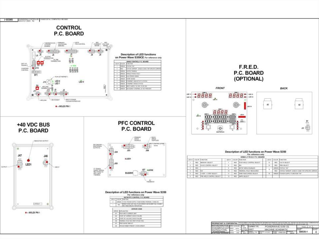
Power Wave® S350 CE & STT Module Service Training
1. Power Wave® S350 CE & STT Module Service Training
Power Wave® S350 CE &STT Module
Service Training
2.
3.
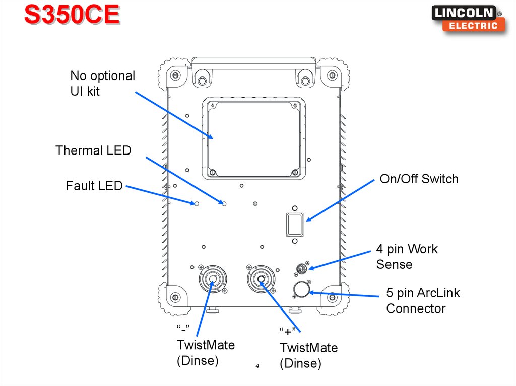
S350CENo optional
UI kit
Thermal LED
On/Off Switch
Fault LED
4 pin Work
Sense
5 pin ArcLink
Connector
“-”
TwistMate
(Dinse)
4
“+”
TwistMate
(Dinse)
4. S350CE
G6682 ControlBoard
CE Filter
5
5. S350CE
Easy access fansEtherNET
Not Used
Circuit
Breaker
Future
Development
Sync Tandem
STT Connector,
part of STT module
Water cooler
Connection
access panel
Optional
DeviceNET
Line Cord
6
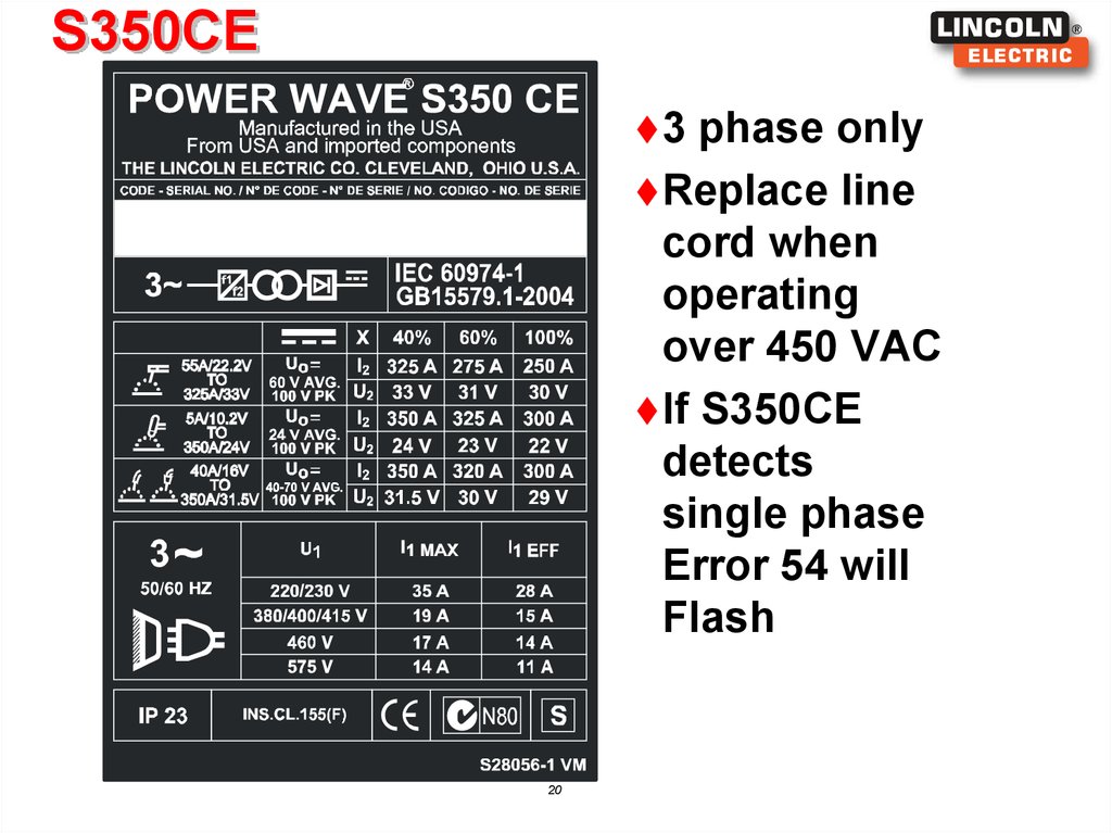
6. S350CE
3phase only
Replace line
cord when
operating
over 450 VAC
7
7. S350CE
OutputChoke
Input
Control
Board
Power
Conversion
Assembly
Input Choke
8
8. S350CE
9.
10.
11.
12.
S350CEFeeder:
13
13. S350CE
SoftwareLocation
– Control Board
Hardware
– Operates with K2921-1 STT Module
– Use PF-25M’s, PF-10M’s LF-45 for feeders
14
14. S350CE
POWERCONVERSION
ASSEMPLY
15.
16.
POWER CONVERSION ASSEMBLY17.
Power Wave S350Power-Up Sequence
– Once voltage is applied to the machine via the input switch, the
auxiliary power supply located on the PFC Control board will turn on.
• This power supply is responsible for regulating the +/- 15 volts for the
control circuits, as well as the +15 volts for the buck & boost IGBTs.
• LED 2 on PFC Control Board indicates a proper functioning power supply.
– Once the auxiliary power supply is functioning, the PFC control and
full bridge circuits will turn on, close a relay, and provide a soft-start
function for the buck-boost power section and simultaneously for the
full bridge inverter located on the Power Conversion Assembly.
• The PFC Control Board soft-start function begins with a low duty cycle
and gradually increases the duty cycle until the buck-boost has met its
pre-charge requirements. Completion time is dependant on the input
voltage to the machine.
18.
Power Wave S350Power-Up Sequence
– After the soft-start sequence is complete, the primary side of the
inverter will be regulated at 400 Volts and the secondary of the
inverter will be 100 Volts.
– The Planar transformer has two auxiliary windings, the first one is
used to provide a 48 Volt power supply for the fans & the DC Bus
Board. The DC Bus Board then provides 40VDC to the Control Board
& Arclink Receptacle (S3 5Pin).
• The 48 Volt secondary follows the same pre-charge sequence as the
100 Volt secondary.
• Fan defaults to low speed unless a weld is made.
– The machine is now idle and ready to make a weld
19.
S350CE3
phase only
Replace line
cord when
operating
over 450 VAC
If S350CE
detects
single phase
Error 54 will
Flash
20
20. S350CE
First Stage Function On the Power Conversion Assembly & PFC PCBRelay Provides Softstart function for DC Link Capacitor
– Limits inrush current during DC Link capacitor charging
–
Activated via open-collector signal from PFC PCB
PFC Control Board
– Powered from the AC line via a diode on the Power Conversion Assembly and an
auxiliary power supply on the PFC Control Board
– Auxiliary power supply requires 180 – 900 Vdc, LED 2 must be on during proper
operation
– Analog and Digital circuits control the current shaping, regulated bus voltage, and gate
drive signals for the main and auxiliary buck and boost switches
Relay Operation
– Under normal operating conditions, the relay should close 50 ms after power is
applied to the machine
– Shorts 100 Ohm resistor after pre-charge
– Under Fault Conditions the relay will generally close 50 ms after power is applied to
the machine and immediately reopen.
Power Conversion Assembly Converts rectified 60Hz input to a regulated 400 Volts dc
– Topology consists of a buck converter followed by a boost converter
21
– Boost switch operates at 230 Vac or less, buck switch is held on (LED 3 is On and LED
11 is On)
– Buck switch operates at 325 Vac or more, boost switch is held off for the most part (LED
3 may be off at idle, LED 11 is ON)
21.
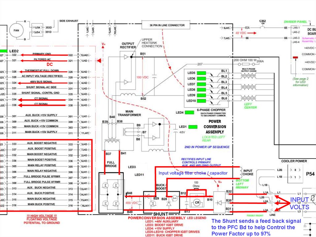
LED2DC
POWER
CONVERSION
ASSEMPLY
Input voltage filter choke / capacitor
INPUT
VOLTS
SHUNT
POWERCONVERSION ASSEMBLY
The Shunt sends a feed back signal
to the PFC Bd to help Control the
Power Factor up to 97%
22.
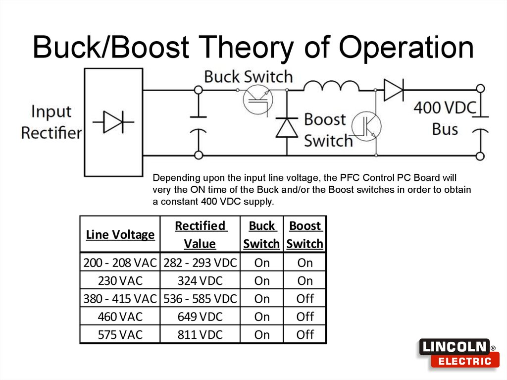
Buck/Boost Theory of OperationDepending upon the input line voltage, the PFC Control PC Board will
very the ON time of the Buck and/or the Boost switches in order to obtain
a constant 400 VDC supply.
Rectified
Buck Boost
Value
Switch Switch
200 - 208 VAC 282 - 293 VDC On
On
230 VAC
324 VDC
On
On
380 - 415 VAC 536 - 585 VDC On
Off
460 VAC
649 VDC
On
Off
575 VAC
811 VDC
On
Off
Line Voltage
23. Buck/Boost Theory of Operation
ThermostatSignal to
Control Board
24.
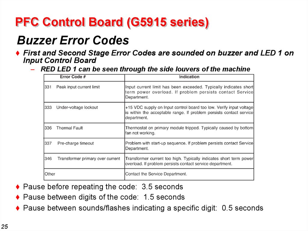
PFC Control Board (G5915 series)Buzzer Error Codes
First and Second Stage Error Codes are sounded on buzzer and LED 1 on
Input Control Board
– RED LED 1 can be seen through the side louvers of the machine
25
Pause before repeating the code: 3.5 seconds
Pause between digits of the code: 1.5 seconds
Pause between sounds/flashes indicating a specific digit: 0.5 seconds
25. PFC Control Board (G5915 series)
Auxiliary Power Supply and PFC Circuits26
26. PFC Control Board (G5915 series)
PFC CONTROL BOARDAuxiliary Power Supply Failure
– Machine will not power up
• LED 2 will be off or blinking if there is a problem with the PFC Control
Board
- Can be seen through side louvers of the machine
• Failure of this circuit will fail the auxiliary input diode
– POWER CONVERSION ASSEMBLY Auxiliary Input Diode Failure
• Use DVM Diode check function from 8J42 to 1J42
– Forward Voltage should be greater than 0.3 Volts
• Failure of this component is a result of a auxiliary power supply failure
27
27. PFC CONTROL BOARD
First Stage Function– Detects thermal trips that may occur on the first stage heatsink (single
thermostat located on the primary module)
Input and Output Signals
Signals from PFC Control Board to Power Conversion Assembly
Connector J23 & J26 on PFC Control Board
Main & Auxiliary Boost Gate Drives
Main & Auxiliary Buck Gate Drives
+15 Volt dc Power Supplies for the Main and Auxiliary Buck Drives
Main Relay Drive
Full Bridge Gate Drives
– Connector J27 on PFC Control Board
• Filter AC Input Power Supply for the Input Control Board
Signals from Power Conversion Assembly to PFC Control Board
– Connector J25 on PFC
• Buck-Boost Current Feedback
• Rectified AC Input Voltage
• Regulated 400 Volt Bus Feedback
• Thermostat Pull-Down Signal
• Full Bridge CT Feedback
28
28.
Primary Thermal ProtectionFunction
Primary Thermal Circuit
– Protects machine against reduced
airflow or overload.
• Fan OFF / Output disabled
• All stages cease operation and machine
appears to be off – Buzzer will continue
to sound
– Location:
• SMT Part, First and Second Stage
Module (M21214-10)
All Thermostats are normally closed
– Mechanical thermostats DO NOT immediately reset!
• First stage module thermostat opens at 90°C, resets at 60°C
Thermostat Test
– Primary Circuit
• G4770 board (6J42 to B49) – should measure short
29
29. Primary Thermal Protection
Relay and DC Link Capacitor3-phase input rectifier converts AC
line voltage to DC
–
100 ohm resistor provides precharge
path for DC Link Capacitor. Relay
closes after precharge is complete.
–
–
–
–
30
Perform diode tests between line
input (B30, B31, B32) and rectifier
outputs (B10, B13)
Measure resistance from B12 to B10
with machine turned off.
100 ohms expected
OPEN indicates resistor failure
SHORT indicates fused relay
contacts
30. Relay and DC Link Capacitor
Power Conversion AssemblyFirst Stage – Buck Boost
31
31. Power Conversion Assembly
Second Stage FunctionsThe Planar transformer has two auxiliary windings.
– The first one is used to provide a 48 Volt power supply for the fans & the DC
Bus Board. Green LED1 on if 48VDC power supply if present on Power Board.
– The DC Bus Board then provides 40VDC to the Control Board & Arclink
Receptacle (S3 5Pin).
Converts rectified 400 Volts dc input to an unregulated 100 Volts dc output
– Topology consists of a full bridge inverter followed by a center tap rectifier
• Full bridge switches at 60 Khz with a 150 ns dead time
• Open-loop control is used and the 100 Volts dc output is unregulated
• Interacts directly with Input Control Board
• Power Board provides primary side current feedback for inverter protection
32
The machine is now idle and ready to make a weld
32.
Planar TransformerDesign Features
Printed circuit board
Individually sealed
Incorporated auxiliary winding
Small footprint allows
for mounting directly onto switchboard
33
33. Planar Transformer
Multi-Phase ChopperFunctions
Used to control welding Voltage and Current
– 100 Volt DC input with regulated output
– Six chopper phases in parallel that turn on 60 degrees out of phase
– Two phases each conduct 180 degrees out of phase through the same
output choke
– Power Board receives commands from the Control board. Power
Board uses this command and determines the on-time of the six
chopper IGBTs.
34
34. Multi-Phase Chopper
FAN ALWAYS ONLOW OR HIGH
48VDC HIGH
24VDC LOW
40VDC
To Control
Board
48VDC
322 to 321=
Input Volts
TO BUS
P.C.BOARD
LED
40VDC
To S1 & S3
For Feeder
100VDC
322 to 324=400
15VDC
POWER
CONVERSION
ASSEMPLY
48VDC
SHUNT
POWERCONVERSION ASSEMBLY
INPUT
VOLTS
35.
Multi-Phase ChopperImplementation
Six LEDs are used to indicate a
turn-on of a chopper phase
– Intensity of each LEDS 5-10 is
related to the on-time of each of
the IGBTs
36
+15 Volt dc power supply for
secondary control circuits
LED4
+ 48 Volt dc auxiliary power
supply indicator LED1
36. Multi-Phase Chopper
Control PC BoardFunctions
Controls
the Chopper power plant
• Transmits welding commands via differential signaling
Controls
welding output based on ...
• User settings
• Voltage and Current feedback
• Welding software
Serves
as the main communication interface
• ArcLink master
• Ethernet
37
37.
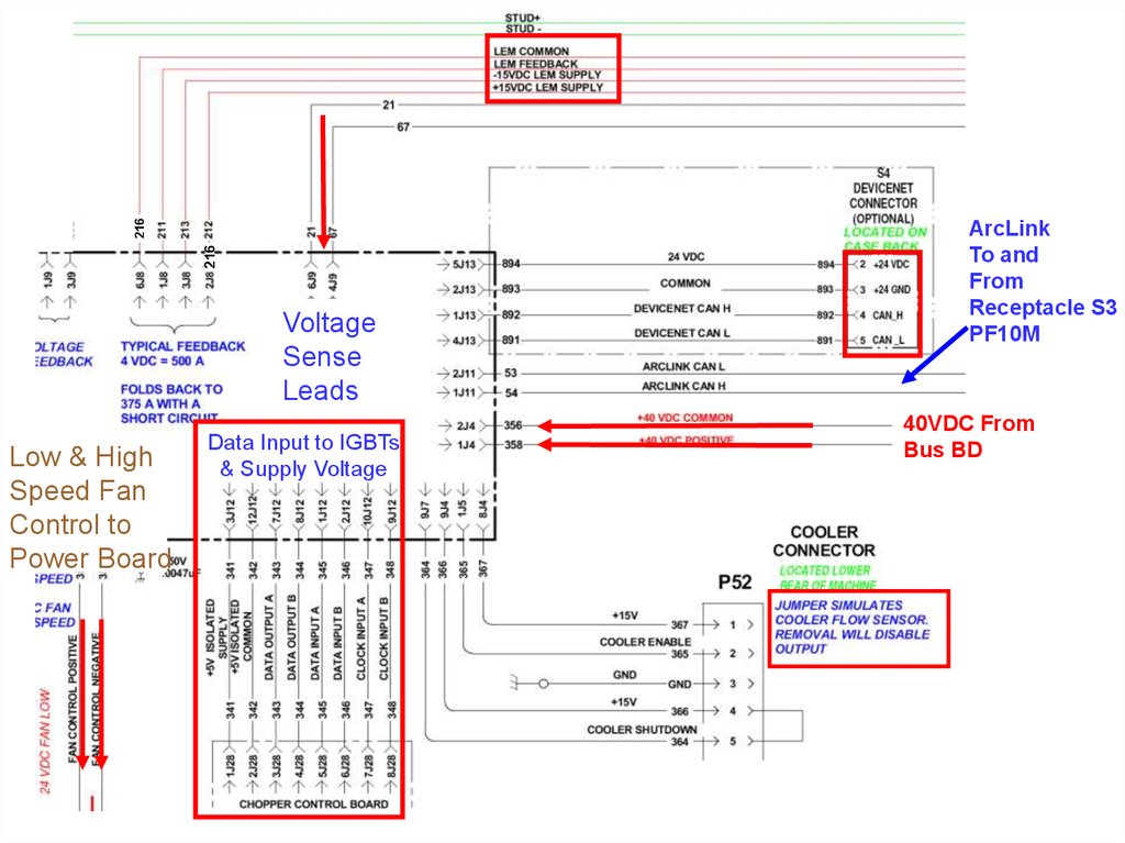
216216
Voltage
Sense
Leads
Low & High
Speed Fan
Control to
Power Board
Data Input to IGBTs
& Supply Voltage
ArcLink
To and
From
Receptacle S3
PF10M
40VDC From
Bus BD
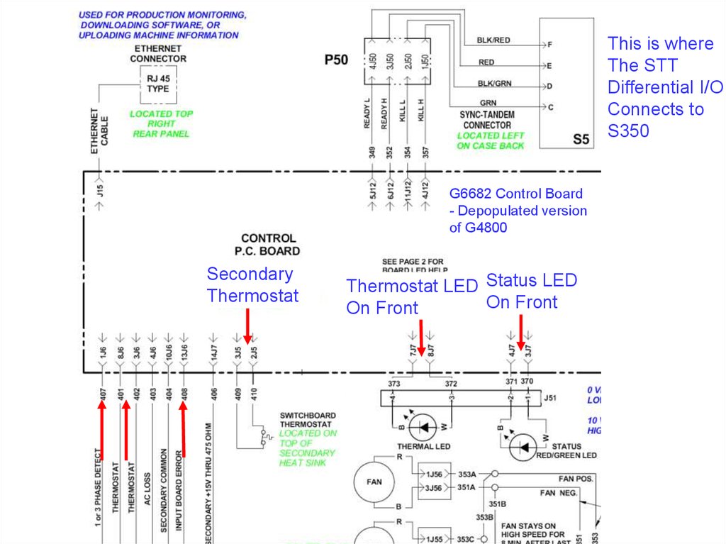
38.
This is whereThe STT
Differential I/O
Connects to
S350
G6682 Control Board
- Depopulated version
of G4800
Secondary
Thermostat
Thermostat LED Status LED
On Front
On Front
39.
Thermal ProtectionFunction
Secondary Thermal Circuit
– Protects machine against reduced
airflow or overload.
• Fan ON / Output disabled
• Thermal fault logged and indicated by
Thermal Error and Thermal LED on User
Interface board (Error 36)
– Locations:
• Secondary Heatsink
All Thermostats are normally closed
– Mechanical thermostats DO NOT immediately reset!
• Secondary heatsink thermostat opens at 68°C, resets at 48°C
– Secondary Circuit
• Digital Control board (2J5 to 3J5) – should measure short
40
40. Thermal Protection
Current Transducer (S18504-6)OUTPUT CURRENT
Simplified Test Procedure
• Verify 30 VDC present at
supply leads
• Check the feedback with a
Constant Current Output into
a load (Mode 200).
- Calibration tab in the
verses actual Output
Current per chart
214
211
213
212
1J8
3J8
2J8
- Verify Transducer Vfb
6J8
“Lincoln Diagnostic Utility”
LEM COMMON
LEM FEEDBACK
-15VDC LEM SUPPLY
+15VDC LEM SUPPLY
500
450
400
350
300
250
200
150
100
50
TYPICAL FEEDBACK
4 VDC = 500 A
CONTROL
P.C. BOARD
(SCHEMATIC G4799)
214
211
213
212
4
3
2
1
MOUNTED ON
BOTTOM OF
OUTPUT CHOKE
_
41
LEM
TRANSDUCER Vfb
(8mV/Amp)
4.0
3.6
3.2
2.8
2.4
2.0
1.6
1.2
0.8
0.4
41. Current Transducer (S18504-6)
Control PC BoardStatus LED’s
DIP Switches – Factory Default Shown
All ON
“Must Have” LED’s
9
Power Supply
1
Board Status
S1
S3
Ethernet Connectivity
7
S2
10
Ethernet Status
• Flashing indicates data
DeviceNet Connectivity
10 DeviceNet Power
42
42.
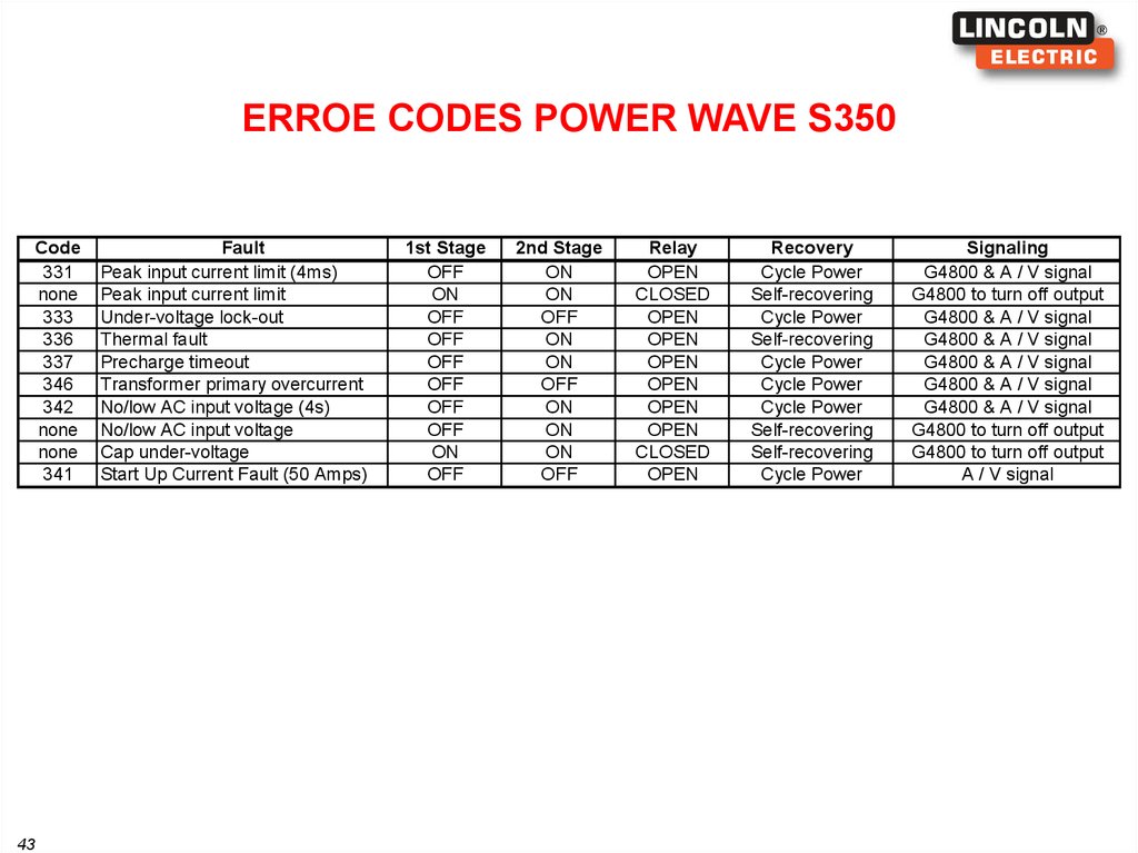
ERROE CODES POWER WAVE S350Code
331
none
333
336
337
346
342
none
none
341
43
Fault
Peak input current limit (4ms)
Peak input current limit
Under-voltage lock-out
Thermal fault
Precharge timeout
Transformer primary overcurrent
No/low AC input voltage (4s)
No/low AC input voltage
Cap under-voltage
Start Up Current Fault (50 Amps)
1st Stage
OFF
ON
OFF
OFF
OFF
OFF
OFF
OFF
ON
OFF
2nd Stage
ON
ON
OFF
ON
ON
OFF
ON
ON
ON
OFF
Relay
OPEN
CLOSED
OPEN
OPEN
OPEN
OPEN
OPEN
OPEN
CLOSED
OPEN
Recovery
Cycle Power
Self-recovering
Cycle Power
Self-recovering
Cycle Power
Cycle Power
Cycle Power
Self-recovering
Self-recovering
Cycle Power
Signaling
G4800 & A / V signal
G4800 to turn off output
G4800 & A / V signal
G4800 & A / V signal
G4800 & A / V signal
G4800 & A / V signal
G4800 & A / V signal
G4800 to turn off output
G4800 to turn off output
A / V signal
43.
STT ModuleService Training
K2921-1
44
44. STT Module
4545.
4646.
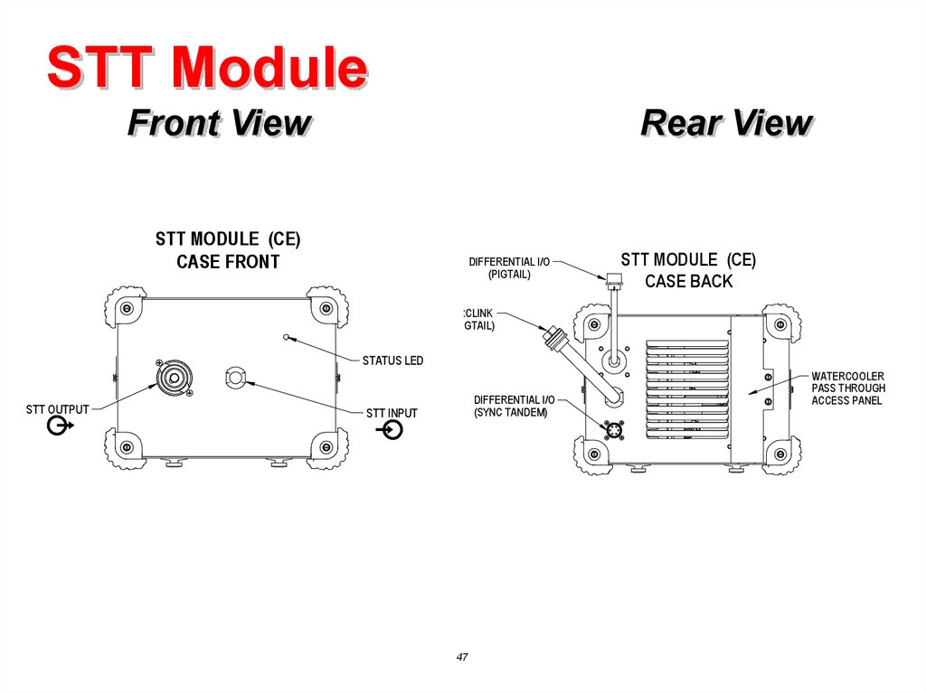
STT ModuleFront View
Rear View
STT MODULE (CE)
CASE FRONT
DIFFERENTIAL I/O
(PIGTAIL)
STT MODULE (CE)
CASE BACK
ARCLINK
(PIGTAIL)
STATUS LED
STT OUTPUT
DIFFERENTIAL I/O
(SYNC TANDEM)
STT INPUT
47
WATERCOOLER
PASS THROUGH
ACCESS PANEL
47.
STT ModuleTypical Mounting
48
48.
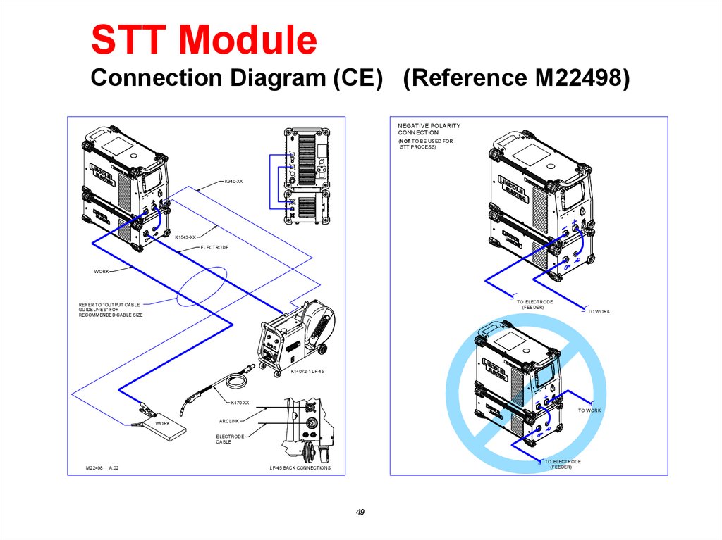
STT ModuleConnection Diagram (CE) (Reference M22498)
NEGATIVE POLARITY
CONNECTION
(NOT TO BE USED FOR
STT PROCESS)
K940-XX
K1543-XX
ELECTRODE
W ORK
TO ELECTRODE
(FEEDER)
REFER TO "OUTPUT CABLE
GUIDELINES" FOR
RECOMMENDED CABLE SIZE
TO W ORK
K14072-1 LF-45
K470-XX
TO W ORK
WORK
ARCLINK
ELECTRODE
CABLE
M22498
A.02
TO ELECTRODE
(FEEDER)
LF-45 BACK CONNECTIONS
49
49.
STT ModuleSTT Update Kit (CE) Included with K2921-1 for S350 CE
67
67A
51
52
51A
52A
53 53A
54 54A
50
50.
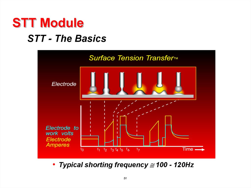
STT ModuleSTT - The Basics
• Typical shorting frequency 100 - 120Hz
51
51. STT Module
Component LocationSTT SWITCH
PC BOARD
AIR EXHAUST
STT STATUS
PC BOARD
SNUBBER
RESISTOR
ASSEMBLY
THERMOSTAT
AIR EXHAUST
AIR INTAKE
52
52.
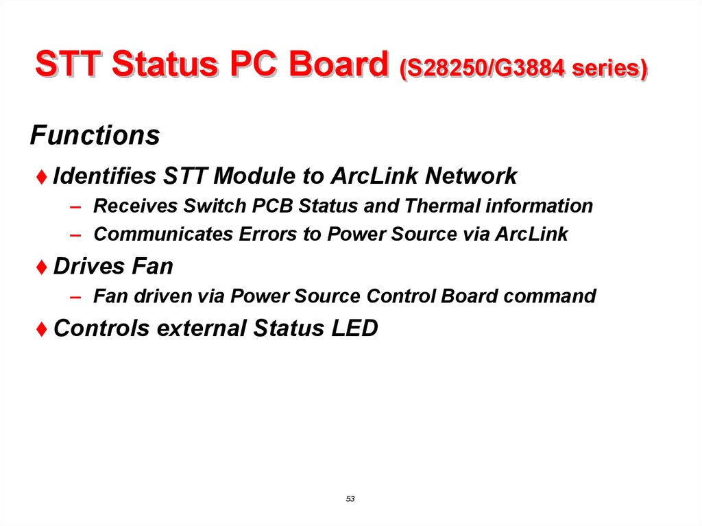
STT Status PC Board (S28250/G3884 series)Functions
Identifies
STT Module to ArcLink Network
– Receives Switch PCB Status and Thermal information
– Communicates Errors to Power Source via ArcLink
Drives
Fan
– Fan driven via Power Source Control Board command
Controls
external Status LED
53
53. STT Status PC Board (S28250/G3884 series)
Arclink40VDC IN
40VDC out
Arclink
Thermostat
851-852
Closed < 1VDC
Open >10VDC
To STT
Switch Board
54
40VDC IN
54.
STT Status PC Board (S28250/G3884 series)55
55. STT Status PC Board (S28250/G3884 series)
Troubleshooting with External LEDNo
LED
– Check LED placement and connections
– Verify 40 Vdc input (J81-4 to J81-3)
Fast
blinking Green LED – Mapping Error
– Verify continuity of ArcLink cable (pins “A” and “B”)
– Verify ArcLink Pigtail to Status PCB
• Pin “A” to J81-1
• Pin “B” to J81-2
Red
and Green Blinking LED
– Read and interpret Error Code
• Power Wave Manager Diagnostic Tab
56
56. STT Status PC Board (S28250/G3884 series)
Troubleshooting with External LEDError codes for the Power Wave STT Module
(Indicated on the externally mounted Status LED)
STT Module
Error Code #
Indication
36
Thermal error
Indicates over temperature. Usually accompanied by Thermal LED on the host
power source. Check fan operation. Be sure process does not exceed duty
cycle limit of the machine.
39
Misc. hardware fault
Unknown glitch has occurred on the fault interrupt circuitry. Sometimes caused
by intermittent connections in the thermostat circuit.
STT Status error
Error reported by the STT Switch PC Board.
Generally caused by misconnection of welding leads (reverse polarity). May
also be caused by loss of input voltage or board failure. Observe diagnostic
LED’s on the STT Switch PC Board to determine the exact cause.
99
Other
A complete list of error codes is available in the Power Wave Manager Utility
(available at www.powerwavesoftware.com).
Error codes that contain three or four digits are defined as fatal errors. These
codes generally indicate internal errors on the Power Source Control Board. If
cycling the input power on the machine does not clear the error, contact the
Service Department.
57
57. STT Status PC Board (S28250/G3884 series)
Troubleshooting Input and Output CircuitsThermostat
Input
– Best Measured across the Thermostat
• Closed < 1VDC
• Open > 10VDC
Switch
PCB Status Input
– Best Measured at STT Switch PC Board (J2-5 to J2-1)
• Closed < 1VDC
• Open > 10VDC
Fan
Output
– Open Collector style (J88-5)
– Supplied from STT Switch PCB (J1-6)
58
58. STT Status PC Board (S28250/G3884 series)
STT Switch PC Board (G6768 series)Functions
Interrupts
Power Source Output Current
– Includes integral snubber diodes and capacitors
• Resistor bank located off Board
Includes
on board Protection Circuitry
– Intelligent Gate Drive
• Minimum ON time = 223µsec
• Maximum OFF time 1.5 seconds
– Under Voltage Lockout (ERROR 99)
– Over Voltage Protection
• Turns Switch ON if Snubber voltage exceeds 500V
– Reverse Polarity Protection (ERROR 99)
• Only when connected through Status PCB (ArcLink)
59
59. STT Switch PC Board (G6768 series)
When welding885 goes to COM
And Fan turns on
To STT 15VDC
Thermostat
Module
In
851-852
Switch
Closed < 1VDC
Status
Open >10VDC
input
40VDC
Input
LED 3
Dif IO Signal
If resistor is
disconnected
Leads 288 & 299
could cause Error 99
With output on
40VDC
Input
60
60.
STT Switch PC Board (G6768 series)DIFFERENTIAL I/O
(STT SWITCH SIGNAL)
STT SWITCH
G6768-1
J3
B1
B2
B3
B4
B9
STT IN
(B1 - B4)
SNUBBER
C1
STT OUT
(B5 - B8)
C2
LED2
LED1
GATE
STATUS
B5
B6
B7
B8
J1
J2
LED3
+15V
STT STATUS
(OUTPUT)
INPUT POWER
(40 VDC)
61
61. STT Switch PC Board (G6768 series)
Functional Block Diagram(6 Pin)
A
B
C
D
E
F
WHT
BLK/WHT
GRN
BLK/GRN
RED
BLK/RED
Schematic: G6767
Assembly: G6768
DIFF I/O (H)
DIFF I/O (L)
J3-1
J3-2
STT IN
(From Power Source)
DIFFERENTIAL I/O
PIGTAIL
(Rear Panel)
UVL
(<10v)
REV
POL
Fault = Disable
GATE
DRIVE
LOGIC
288
24 uF
2 Ohm / 300W
STATUS
LOGIC
2 Ohm / 300W
SSR
Fault = ON
2 Ohm / 300W
STATUS (SIGNAL)
STATUS (+)
THERMOSTAT SUPPLY (+)
289
ON > 223usec
OFF < 1.5 sec
+40VDC
COMMON
Green LED
(Board Status)
ON/OFF
OVER
VOLTAGE
( > 500V )
(SSR)
Red LED
(Gate Drive)
854
52C
52B
51B
J2-1
851
826
6J1
1J1
3J1
J2-5
J2-6
Red LED
(15V Supply)
62
STT OUT
(To Feeder / Arc)
62. STT Switch PC Board (G6768 series)
Gate Drive Signal (RS-485 Differential signal from Power Source)(6 Pin)
A
B
C
D
E
F
WHT
BLK/WHT
GRN
BLK/GRN
RED
BLK/RED
J3-1
J3-2
DIFF I/O (H)
DIFF I/O (L)
ON/OFF
DIFFERENTIAL I/O
PIGTAIL
(Rear Panel)
GATE
DRIVE
LOGIC
Schematic: G6767
Assembly: G6768
DIFFERENTIAL GATE SIGNAL
+2.5
Vba
(J3-1 to J3-2)
-2.5
Green LED
(Board Status)
Red LED
(Gate Drive)
TYPICAL STT
OUTPUT CURRENT
WAVEFORM
63
63. STT Switch PC Board (G6768 series)
Snubber ConfigurationCapacitor
– Absorbs initial energy
Resistor
– Limits maximum voltage
– Provides path to sustain
arc current
– Dissipates Energy from
weld circuit inductance
24 uF
64
.66 Ohm /
300W
64. STT Switch PC Board (G6768 series)
TroubleshootingOn Board LED’s for the STT Switch PC Board
(Visible through the rear and left side louvers)
STT Switch PC Board
MACHINE
OUTPUT
LED1
(GATE)
LED2
(STATUS)
LED3
(+15V)
Indication
ON/OFF
ON
ON
ON
Normal Condition – STT Switch is ON
ON
OFF
ON
ON
Normal Condition – STT Switch has been commanded OFF
Note: During normal STT operation the OFF state of the LED may
only be detectable as a slight dimming.
ON
OFF
OFF
ON
Status Failure (only when triggered). Should be accompanied by
Error 99 on the external STT Module Status LED. Most likely caused
by weld cable misconnection (reverse polarity).
ON/OFF
Status Failure (constantly). Should be accompanied by Error 99 on
the external STT Module Status LED. Most likely caused by the on
board power supply under-voltage lockout. Verify input voltage to the
STT Switch board.
ON/OFF
OFF
OFF
65