
")


 Физика
 Английский язык
Похожие презентации:


Alternating current. (Lecture 3)
1.
Physics 2Voronkov Vladimir Vasilyevich
2. Lecture 3
Alternating Current (AC)
Inductors in AC Circuits
Capacitors in AC Circuits
Series RLC Circuit
Impedance
3. Alternating Current (AC)
• The voltage supplied by an AC source isharmonic (sinusoidal) with a period T.
• AC source is designated by
4.
Applying Kirchhoff’s loop, at any instant:The instantaneous current in the resistor is:
5.
Where Imax is the maximum current:And eventually:
Plots of the instantaneous current iR
and instantaneous voltage vR
across a resistor as functions of
time. The current is in phase with
the voltage, which means that the
current is zero when the voltage is
zero, maximum when the voltage is
maximum, and minimum when the
voltage is minimum. At time t = T,
one cycle of the time-varying
voltage and current has been
completed.
So, for a sinusoidal applied voltage, the current in a resistor
is always in phase with the voltage across the resistor.
6. Phasor Diagrams
A phasor is a vector whose length isproportional to the maximum value of the
variable it represents (Vmax for voltage
and Imax for current in the present
discussion) and which rotates
counterclockwise at an angular speed
equal to the angular frequency
associated with the variable. The
projection of the phasor onto the vertical
axis represents the instantaneous value
of the quantity it represents.
7.
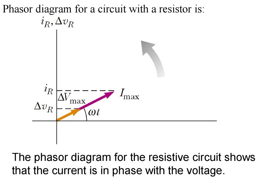
Phasor diagram for a circuit with a resistor is:The phasor diagram for the resistive circuit shows
that the current is in phase with the voltage.
8.
The projections of the phasor arrows onto thevertical axis are determined by a sine function of the
angle of the phasor with respect to the horizontal
axis. We can use the projections of phasors to
represent values of current or voltage that vary
sinusoidally in time.
9. RMS
The average value of the current over onecycle is zero. What is of importance in an
AC circuit is an average value of current,
referred to as the rms current.The notation
rms stands for root-mean-square, which in this
case means the square root of the mean
(average) value of the square of the current:
10.
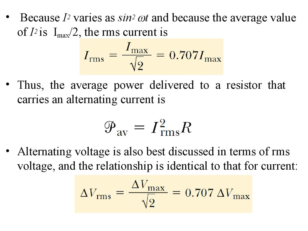
• Because I2 varies as sin2 t and because the average valueof I2 is Imax/2, the rms current is
• Thus, the average power delivered to a resistor that
carries an alternating current is
• Alternating voltage is also best discussed in terms of rms
voltage, and the relationship is identical to that for current:
11.
One reason we use rms values when discussingalternating currents and voltages in this chapter
is that AC ammeters and voltmeters are designed to
read rms values. Furthermore, with rms values,
many of the equations we use have the same form as
their direct current counterparts.
12. Inductors in AC Circuits
Kirchhoff’s rule for ACcircuit with an inductor is:
After derivation we get:
iL is the current through the inductor L.
For a sinusoidal applied voltage, the current in an inductor
always lags behind the voltage across the inductor by 90°
(one-quarter cycle in time).
13.
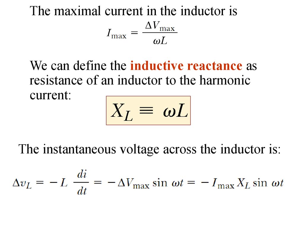
The maximal current in the inductor isWe can define the inductive reactance as
resistance of an inductor to the harmonic
current:
The instantaneous voltage across the inductor is:
14.
Plot of the instantaneouscurrent iL and instantaneous
voltage vL across an
inductor as functions of
time. The current lags
behind the voltage by 90°.
Phasor diagram for the
inductive circuit,
showing that the
current lags behind the
voltage by 90°.
15. Capacitors in AC
The current is /2 rad =90° out of phase with
the voltage across the
capacitor:
For a sinusoidally applied voltage, the current
always leads the voltage across a capacitor by
90°.
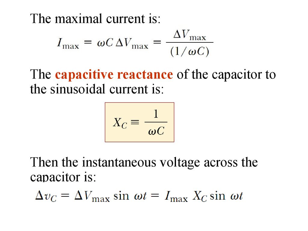
16.
The maximal current is:The capacitive reactance of the capacitor to
the sinusoidal current is:
Then the instantaneous voltage across the
capacitor is:
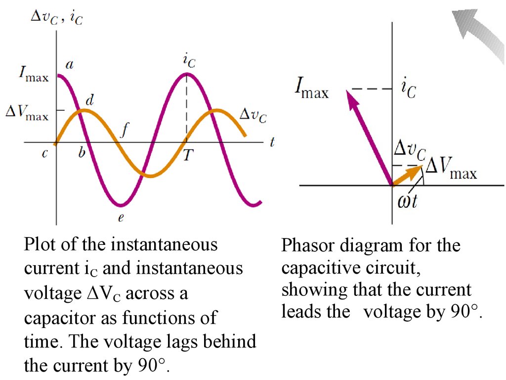
17.
Plot of the instantaneouscurrent iC and instantaneous
voltage VC across a
capacitor as functions of
time. The voltage lags behind
the current by 90°.
Phasor diagram for the
capacitive circuit,
showing that the current
leads the voltage by 90°.
18. The RLC Series Circuit
For convenience, and notlosing generalization, we
can assume that the
applied voltage is
and the current is
Where =const is some phase angle between the current
and the applied voltage. Because the elements are in
series, the current everywhere in the circuit must be the
same at any instant. That is, the current at all points in
a series AC circuit has the same amplitude and phase.
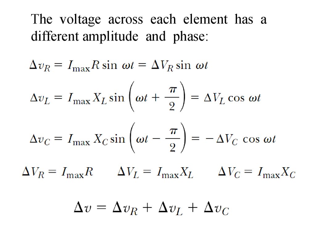
19.
The voltage across each element has adifferent amplitude and phase:
20.
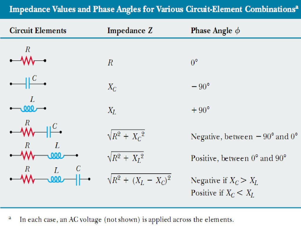
21. Impedance
Using the previous calculations we can define a newparameter impedance:
So, the amplitudes of voltage and current are related
as
Using the phasor diagram:
22.
23. Power in AC Circuit
• The average power delivered by the source isconverted to internal energy in the resistor.
• No power losses are associated with pure
capacitors and pure inductors in an AC circuit.
24. Series RLC Circuit Resonance
A series RLC circuit is in resonance when the current hasits maximum value.
So resonance is at XL=XC, the frequency 0 when XL=XC is
called the resonance frequency:
This frequency corresponds to the natural frequency of
oscillation of an LC circuit
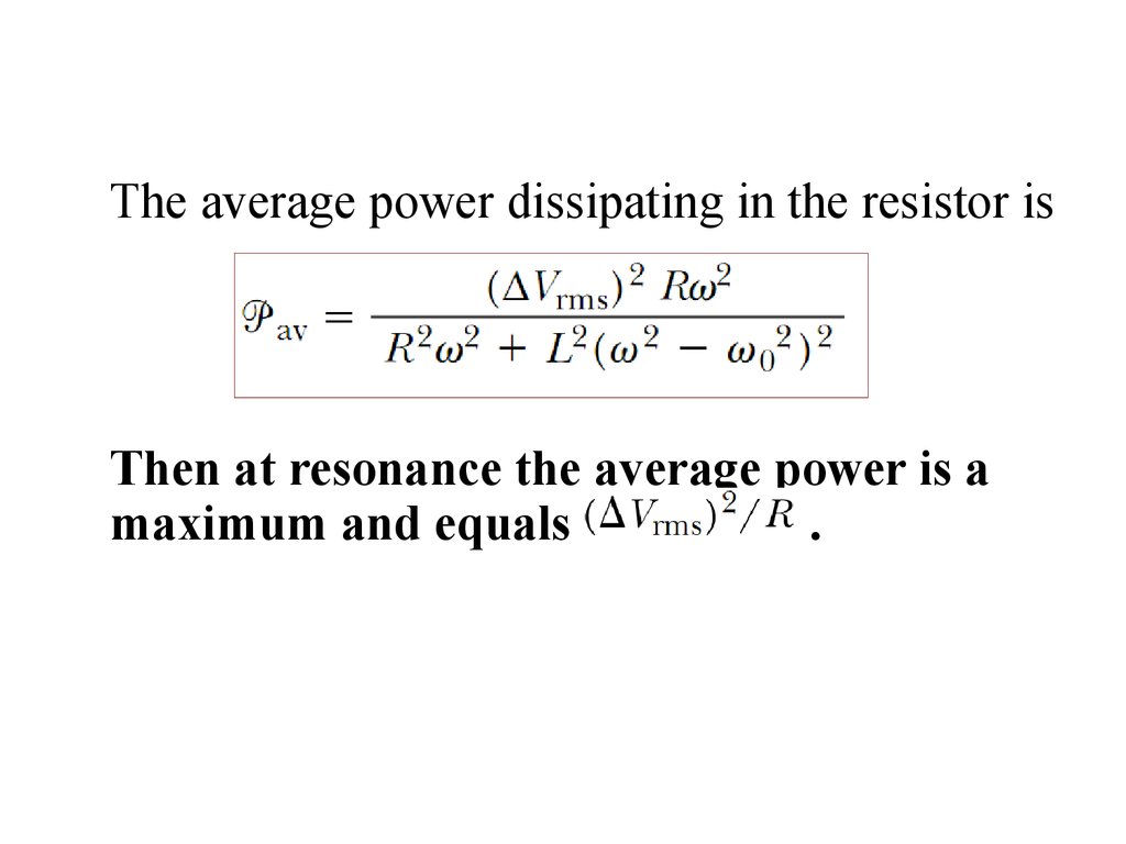
25.
The average power dissipating in the resistor isThen at resonance the average power is a
maximum and equals
.
26. Units in Si
voltage (potential difference) V
current (electric current)
I
inductance
L
inductive reactance
XL
capacitive reactance
XC
Impedance
Z
Power
P
V (Volt)
A (Ampere)
H (Henry)
Ohm)
Ohm)
Ohm)
W (Watt)