


 Английский язык
Похожие презентации:


")

")

Marker beacon system
1.
Marker beacon system2.
3.
4.
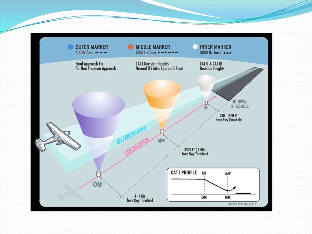
A marker beacon is a particular type of VHF radio beacon used inaviation, usually in conjunction with an instrument landing system (ILS), to
give pilots a means to determine position along an established route to a
destination such as a runway.
According to Article 1.107 of the International Telecommunication Union´s
(ITU) ITU Radio Regulations (RR)[1] a marker beacon is defined as A
transmitter in the aeronautical radionavigation service which radiates
vertically a distinctive pattern for providing position information to aircraft.
5.
HistoryFrom the 1930s until the 1950s, markers were used extensively along airways to
provide an indication of an aircraft's specific position along the route, but from the
1960s they have become increasingly limited to ILS approach installations. They are
now very gradually being phased out of service, especially in more developed parts of
the world, as GPS and other technologies have made marker beacons increasingly
obsolete.
6.
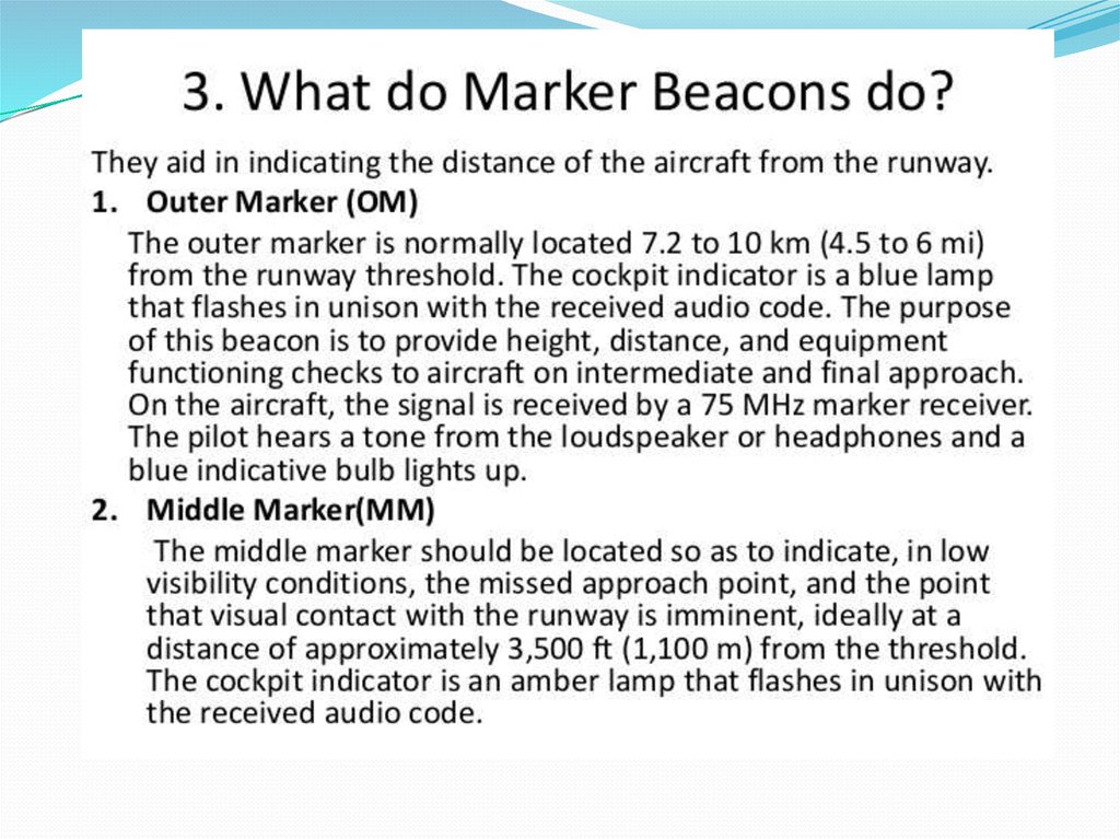
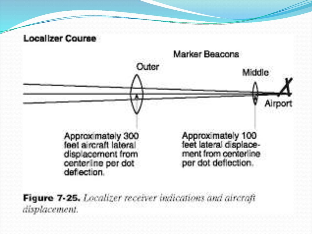
The Outer Marker, which normally identifies the finalapproach fix (FAF), is situated on the same course/track as the
localizer and the runway center-line, four to seven nautical
miles[2] before the runway threshold. It is typically located
about 1 NM (1.85 km) inside the point where the glideslope
intercepts the intermediate altitude and transmits a 400 Hz tone
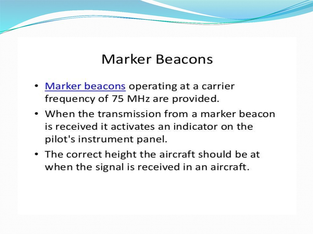
signal on a low-powered (3 watts), 75 MHz carrier signal. Its
antenna is highly directional, and is pointed straight up. The
valid signal area is a 2,400 ft (730 m) × 4,200 ft (1,280 m) ellipse
(as measured 1,000 ft (300 m) above the antenna.) When the
aircraft passes over the outer marker antenna, its marker beacon
receiver detects the signal. The system gives the pilot a visual
(blinking blue outer marker light) and aural (continuous series
of audio tone morse code-like 'dashes') indication.
7.
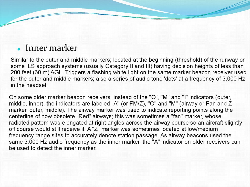
Inner markerSimilar to the outer and middle markers; located at the beginning (threshold) of the runway on
some ILS approach systems (usually Category II and III) having decision heights of less than
200 feet (60 m) AGL. Triggers a flashing white light on the same marker beacon receiver used
for the outer and middle markers; also a series of audio tone 'dots' at a frequency of 3,000 Hz
in the headset.
On some older marker beacon receivers, instead of the "O", "M" and "I" indicators (outer,
middle, inner), the indicators are labeled "A" (or FM/Z), "O" and "M" (airway or Fan and Z
marker, outer, middle). The airway marker was used to indicate reporting points along the
centerline of now obsolete "Red" airways; this was sometimes a "fan" marker, whose
radiated pattern was elongated at right angles across the airway course so an aircraft slightly
off course would still receive it. A "Z" marker was sometimes located at low/medium
frequency range sites to accurately denote station passage. As airway beacons used the
same 3,000 Hz audio frequency as the inner marker, the "A" indicator on older receivers can
be used to detect the inner marker.
8.
Back course markerA back course marker (BC) normally indicates the ILS back course
final approach fix where approach descent is commenced. Its cockpit
audio and visual indications are the same as for an inner marker (IM),
but its location on the approach course is very different (final
approach fix for BC vs. runway threshold for IM).[4]
Fan marker
The term fan marker refers to the older type of beacons used mostly
for en-route navigation.[5][6] Fan-type marker beacons were
sometimes part of a non-precision approach and are identified by a
flashing white light and a repeating dot-dash-dot signal.[7] Recent
editions of the FAA's AIM publication no longer mention fan
markers.[4][8]