


 Электроника
Похожие презентации:


Fiber-optic pressure instrument transducers
1.
Fiber-optic pressure instrument transducersN.D. Koshevoy, d.tech.sc., National Aerospace University
named after N.E. Zhukovskiy “KhAI”
A.V. Zabolotniy, d.tech.sc., National Aerospace University
named after N.E. Zhukovskiy “KhAI”
E.M. Kostenko, d.tech.sc., Poltavska derjavna agrarna akademiya
I.I. Koshevaya, postgraduate student, National Aerospace
University named after N.E. Zhukovskiy “KhAI”
T.G. Rozhnova, Kharkiv National University of Radioelectronics
V.V. Muratov, postgraduate student, National Aerospace University
named after N.E. Zhukovskiy “KhAI”
Kharkiv, 2019
2.
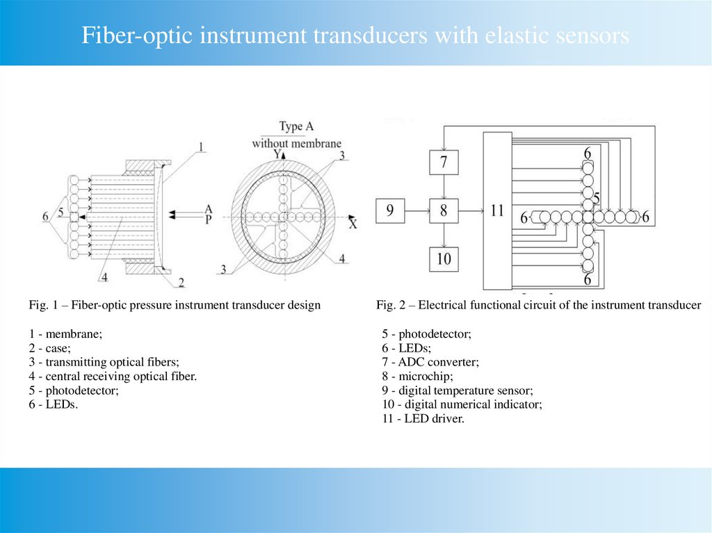
Fiber-optic instrument transducers with elastic sensorsFig. 1 – Fiber-optic pressure instrument transducer design
1 - membrane;
2 - case;
3 - transmitting optical fibers;
4 - central receiving optical fiber.
5 - photodetector;
6 - LEDs.
Fig. 2 – Electrical functional circuit of the instrument transducer
5 - photodetector;
6 - LEDs;
7 - ADC converter;
8 - microchip;
9 - digital temperature sensor;
10 - digital numerical indicator;
11 - LED driver.
3.
Fiber optic pressure sensor using a mathematical model of themeasurement process
{
6
7
9
8
11
5
{
10
6
Fig. 3 – Fiber-optic pressure instrument transducer construction
1 - membrane sensor;
2 - case;
3 - transmitting optical fibers;
4 - receiving optical fiber;
5 - photodetector;
6 - LEDs.
Fig. 4 – Electrical functional circuit of the instrument transducer
5 - photodetector;
6 - LEDs;
7 - ADC converter;
8 - microcontroller;
9 - temperature sensor;
10 - indicator;
11 - LED driver.
4.
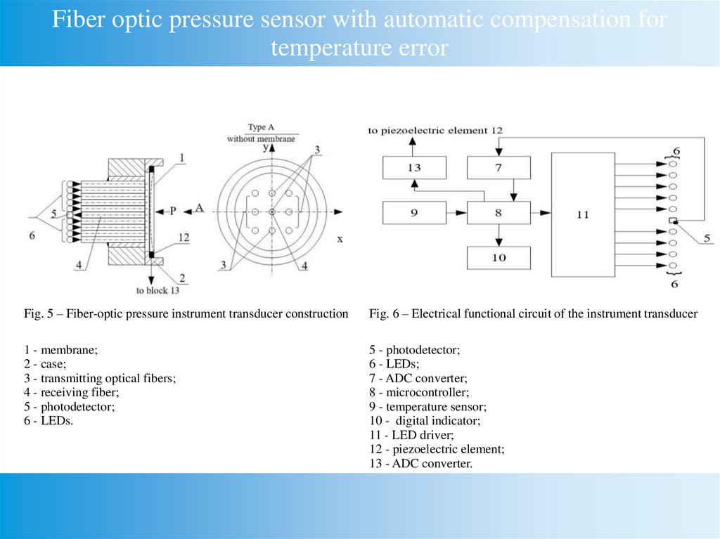
Fiber optic pressure sensor with automatic compensation fortemperature error
Fig. 5 – Fiber-optic pressure instrument transducer construction
Fig. 6 – Electrical functional circuit of the instrument transducer
1 - membrane;
2 - case;
3 - transmitting optical fibers;
4 - receiving fiber;
5 - photodetector;
6 - LEDs.
5 - photodetector;
6 - LEDs;
7 - ADC converter;
8 - microcontroller;
9 - temperature sensor;
10 - digital indicator;
11 - LED driver;
12 - piezoelectric element;
13 - ADC converter.
5.
Fiber optic pressure sensor with integrated control{
6
12
7
9
8
11
5
{
10
6
Fig. 7 – Fiber-optic pressure instrument transducer construction
1 - sensor;
2 - case;
3 - transmitting optical fibers;
4 - receiving fiber;
5 - photodetector;
6 - LEDs.
Fig. 8 – Electrical functional circuit of the instrument transducer
5 - photodetector;
6 - LEDs;
7 - ADC converter;
8 - microcontroller;
9 - temperature sensor;
10 - digital indicator;
11 - LED driver;
12 - amplifier.
6.
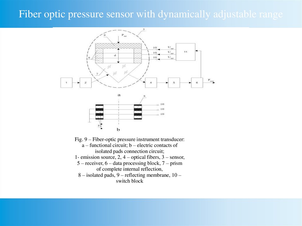
Fiber optic pressure sensor with dynamically adjustable rangeFig. 9 – Fiber-optic pressure instrument transducer:
a – functional circuit; b – electric contacts of
isolated pads connection circuit;
1- emission source, 2, 4 – optical fibers, 3 – sensor,
5 – receiver, 6 – data processing block, 7 – prism
of complete internal reflection,
8 – isolated pads, 9 – reflecting membrane, 10 –
switch block
7.
Fiber optic pressure sensor with dynamically adjustable rangeand integrated control
a
b
Fig. 10– Fiber-optic instrument transducer with embedded control:
а – functional circuit,
b – electrical contacts of isolated pads connection circuit
8.
Fiber optic pressure sensors for measuring the weight ofmoving objects
3
9
6
7
8
3
9
8
6
7
2
2
4
4
5
5
1
1
Fig. 11– Fiber-optic pressure instrument transducer’s sensor design
Fig. 12 – Simplified sensor’s design of a fiber-optic
pressure instrument transducer
9.
ConclusionsFiber-optic pressure instrument transducers with elastic
sensors, dynamically tuned measurement range, to measure weight
of mobile objects were proposed.
Functional circuits of developed fiber-optic instrument
transducers and the description of their work are given. Fiber-optic
instrument transducers are protected with utility model patents of
Ukraine.
Developed fiber-optic pressure instrument transducers can be
widely applied in information-measuring systems and in control
systems for different objects.