Похожие презентации:
Vesta-P2a SP C360DNw
1.
Vesta-P2aSP C360DNw
Vesta-MF2ab
SP C360SFNw
SP C360SNw
SP C361SFNw
Technical Training
Full class room training
2. Objectives
After completing this training you should be able to:Install the SP C360 series in the field
Instruct the customer
Trouble shoot and repair the engine in the field
Perform maintenance
2
3. Requirements
SP C360DNw and SP C361SFNwService manual
This Presentation
3
4. Pre requisites & Exam
Pre requisites & ExamBefore starting this training you must already have followed the
My-Ricoh training for:
Digital imaging V2 – HW servicing
Colour Awareness R2- Introduction
Smart Operation Panel V2 – HW Servicing
At the end of this course, you can do the exam on:
www.my-ricoh.com
4
5.
1. Product Outline5
6. What Models?
Vesta-P2a (M0B0) SP C360DNwsGW basic controller, 30 ppm, 28 ppm (duplex)
Vesta-MF2a (D0A0, 4 in 1) SP C360SFNw
Vesta-MF2a (D0AA, 3 in 1) SP C360SNw
sGW basic controller, 30 ppm, 28 ppm (duplex)
Vesta-MF2b (D0AB) SP C361SFNw
sGW value controller, 30 ppm, 28 ppm (duplex)
Low-end A4 printer
sGW basic & value Controller (17S)
Contains PostScript3, Gigabit Ethernet, duplex unit, and bypass
tray as standard equipment.
6
7. New CTL: sGW concept
SIMVA controller is changed to ‘’sGW’’ controller.‘’sGW’’ controller has 2 concepts, value added and basic.
Category
Value
added
Basic
CTL name
-
SIMVA
sGW
Model concept
sGW value
(MF2b)
sGW basic
(MF2a/P2a)
(Same concept as SIMVA)
sGW: (selectable/smart/simple GW)
7
8. sGW CTL Basic function(Common with GW+)
sGW CTL Basic function Common with GW+)C T L B asic Fu n ction
Features
U tility
S ecurity
D evice
m anagem ent
N etw ork
C opy/S can
C ontent
@ R em ote
A ccess control
U ser code authentification
W indow s/LD A P A uthentication
R em aining toner
E-m ail alert
Q uota S etting/A ccount Lim it
R em ote operation panel
W IM support
W ireless LA N
A uto T ray S w itch
Paper selection (from panel)
ID card C opy
C om bine C opy (2in1)
S can to U S B /S D
T W A IN S can
PC L5/PC L6
Postscript3 em ulation
M edia D irect Print
Locked Print
S ort
Econom y Printing M ode
A irPrint
GW +
Y
Y
Y
Y
Y
Y
Y
Y
Y
N
Y
Y
Y
Y
Y
Y
Y
Y
Y
Y
Y
Y
N
sG W
(V alue)
Y
Y
Y
Y
Y
Y
Y
Y
Y
Y
Y
Y
Y
Y
Y
Y
Y
Y
Y
Y
Y
Y
Y
sG W
(B asic)
Y
Y
Y
Y*
Y
Y
Y
Y
Y
Y
Y
Y
Y
Y
Y
Y
Y
Y
Y
Y
Y
Y
Y
C om m ent
Im p ro ve d fro m K IB O C T L
* O n ly M F2 a is su p p o rte d .
(1 0 0 1 0 % , n e a r e n d /e n d a le rt)
A le rt m a ch in e co n d itio n s to a d m in istra to r
G W + is o p tio n a l
8
9. sGW CTL Basic function(Differences with GW+)
sGW CTL Basic function Differences with GW+)C T L B asic Fu n ction
Features
C opy/S can
D ocum ent box
S ecurity
U tility
C ontent
A uto C olor S election
2 color C opy
C om bined S ize C opy/S can
D irectional M agnification
C om bine (O ver 4in1/B ooklet
Front C over S heet
Endorse
D ocum ent box
R PC S
B asic D river
PD F Encryption
Eco report
GW +
Y
Y
Y
Y
Y
Y
Y
Y
Y
Y
Y
Y
sG W
(V alue)
N
N
N
N
N
N
N
N
N
N
N
N
sG W
C om m ent
(B asic)
N
N
N
N
2 in 1 is su p p o rte d .
N
N
N
N
N
N
N
N
9
10. sGW CTL Value-added functions
V alu e-added Fu n ctionFeatures
S oftw are
S I support
C ontent
D -S D K JA V A -S D K
B row ser
A pplication S ite (Z oo)
C heetah A pps (D ow nload via C loud)
S I-C loud (A pplication support)
S I-C loud (W orkflow developm ent tool)
3rd V endor A pps
GW +
Y
Y
Y
Y
Y
Y
Y
sG W
(V alue)
N
Y
Y
Y
Y
Y
Y*
sG W
C om m ent
(B asic)
S m a rt S D K is su p p o rte d .
N
N
N
N
N
N
* D e p e n d s o n h o w th e ve n d o r d e ve lo p s th e A p p s.
N
10
11. sGW CTL Hardware support
H ardw are su pportGW +
sG W
(V alue)
sG W
(B asic)
Y
Y
N
N FC (sm art device connection)
Y
Y
Y
M em ory
N IC 2 port
W ireless LA N
Y
Y
Y
N
N
Y
N
N
Y
HDD
Y
Y*
N
K ey C ard
Y
N
N
Features
C ontent
A uthentification N FC (IC card R /W ) *O ptional
O ption
C om m ent
G lo ria is n o t su p p o rte d * .
* T h is is fo r 3 rd ve n d o r so ftw a re a n d A p p s.
- Q u ick co n n e ctio n fo r R im o co .
- sG W is su p p o rte d a s S T D .
sG W is su p p o rte d a s S T D .
S D ca rd is su p p o rte d a s S T D fo r in te rn a l
sto ra g e .
11
12. sGW CTL Cheetah Apps support
Specific functions of Cheetah will be supported for MF models*.*sGW basic model will not support Browser NX, Zoo, an ICE.
C h eetah A pps
Features
B a sic
C ontent
B ro w se r (A n d ro id )
B ro w se r N X
A p p lica tio n S ite (Z o o )
S m a rt se rie s
S m a rt C o p y/S m a rt Fa x/S m a rt S ca n
Q u ick se rie s
Q u ick C o p y/Q u ick Fa x/Q u ick S ca n
W id g e t
V a rio u s W id g e ts
(S yste m m e ssa g e /Fa x
re ce p tio n /R e m a in in g T o n e r/T im e &
D a te /R e m a in in g p a p e r/S e tu p /M o b ile
co n n e ctio n /e tc.)
E co W id g e t
S p e cfic u se
ID C a rd co p y
ID C a rd S ca n /P rin t
N a vig a to r fo r fo ld e r a d d re ss se tu p
S ca n to M e
Q R C o d e (fo r H e d g e H o g )
C lo u d Fa x
O th e rs
IC E (C lo u d A p p s)
C a m e l (R e m o te A ssist)
Y
Y
Y
Y
Y
sG W
(V alue)
Y
Y
Y
Y
Y
sG W
(B asic)
N
N
N
Y
Y
Y
Y
Y
Y
Y
Y
Y
Y
Y
Y
Y
Y
N
Y
Y
Y
Y
Y
Y
Y*
TBD
N
Y
Y
Y
N
Y
Y
N
TBD
GW +
C om m ent
* T o b e e va lu a te d .
12
13. sGW CTL Solution support
R icoh softw areFeatures
D e vice
M anagem ent
C ontent
U Z -A 1 (a p p lia n ce b o x)
B ird ie (D e vice M a n a g e r N X )
Ib is(P rin te r D rive r P a cka g e r N X )
In te g ra te so lu tio n
R IS (S tre a m lin e N X )
C a p tu re &
D istrib u tio n
X G -S D (G lo b a l S ca n N X )
O u tp u t so lu tio n
K a ra ch i(Fle xR e le a se C X )
Isp i(R IC O H S ca n N X )
G lo ria (E n h a n ce d Lo cke d P rin t N X )
GW +
Y
Y
Y
Y
Y
Y
Y
Y
sG W
(V alue)
Y
Y
Y
N
N
N
N
N
sG W
(B asic)
Y
Y
Y
N
N
N
N
N
C om m ent
13
14. Main Points
LED print headQSU fusing unit
SPDF including ID card copy/scan
Installation and maintenance can be done by users
Including installation of optional paper tray units.
14
15. Appearance
One optional tray canbe installed (not
shown).
Duplex and bypass are
standard.
There are no finishers.
There is an external
USB slot by the
operation panel.
The cover below the
operation panel (in
the red circle) slides
up to reveal these
slots.
One paper tray
is standard
15
16. Appearance
One optional tray canbe installed (not
shown).
SPDF is standard.
Duplex and bypass are
standard.
There are no finishers.
There is an external
USB/SD slot on the
side of the operation
panel.
One paper tray
is standard
16
17. Hardware Options
Also used with thesenew models:
Paper Feed Unit
TK1230
Note
New
250 sheets
New
500 sheets
(M407)
Paper Feed Unit
TK1240
(M408)
17
18. Controller Memory
Memory:Standard memory: 2 GB
No upgrades.
An internal SD card inside the SP C361SFNw can be used for
storage.
SP C361SFNw Only
18
19. Ports on the Controller Board (printer)
Ethernet port: Use a networkinterface cable to connect the
printer to a network.
USB port B: Use a USB cable to
connect the printer to a computer.
USB (type A): Used for custom
option cumin-3G (3G dongle).
Mini USB: Used for debug log via
debug log cable.
SD card slot: Used for firmware
update by technician.
19
20. Ports on the Controller Board (MF)
Ethernet port: Use a network interface cable toconnect the printer to a network.
USB port B: Use a USB cable to connect the
printer to a computer.
USB (type A): Used for custom option cumin-3G
(3G dongle).
Mini USB: Used for debug log via debug log
cable.
Micro SD-card slot: used for additional memory.
SD card slot: Used for firmware update by
technician.
RJ11 connection: Fax Connection
20
21. General Specifications
Input Tray CapacityStandard Tray:250 sheets
Bypass tray: 100 sheets
Optional Paper Feed Unit: 250 or 500 sheets
Maximum
850 sheets total capacity (Std tray + Option*1 + Bypass)
Output Tray Capacity (Face down)
Up to 200 sheets
21
22. General Specifications (3/4)
Paper Size:Standard tray: A4/LT SEF – A6/HLT LEF
Non-standard sizes: Width: 82.5 - 216 mm (3.25" – 8.5"),
Length: 148 - 356 mm (5.8" - 14.0")
Optional tray: A4/LT SEF – A5/HLT LEF
Non-standard sizes: Width: 139.7 - 216 mm (5.5" – 8.5"),
Length: 210 - 356 mm (8.3" - 14.0")
Bypass tray: A4/LT SEF – A6/HLT LEF
Non-standard sizes: Width: 64 - 216 mm (2.5" – 8.5"), Length:
127 - 1260 mm (5.0" - 49.6")
Duplex: A4/LT SEF – A6/HLT LEF
Non-standard sizes: Width: 100 - 297 mm (3.9" - 11.7"), Length:
148 - 432 mm (5.8" - 17.0")
Paper Weight
Standard Tray: 56 - 220 g/m2 (15 lb. Bond - 80 lb. Cover)
Bypass tray: 56 - 220 g/m2 (15 lb. Bond - 80 lb. Cover)
Duplex: 56 - 163 g/m2 (15 lb. Bond - 90 lb. Index)
Optional Paper Feed Unit: 56 - 220 g/m2 (15 lb. Bond - 80 lb. Cover)
22
23. General Specifications (4/4)
Memory: 2 GBInterface
Rear
Ethernet interface (1000BASE-T/100BASE-TX/10BASE-T) x1
IEEE 802.11a/b/g/n wireless LAN interface x1
USB 2.0-Device (Type B) x1
Front
USB 2.0-Host (Type A) x1
SD card slot x1 (MF Only)
PDL
Standard: PJL, PCL 5c/XL, IRIPS PostScript 3, MediaPrint (TIFF,
IRIPS PDF)
23
24. Targets
APV, per month1.2k
Color Ratio
50%
MPBF (Mean Prints
Between Failure)
70k
Call ratio (Mainframe)
0.021
Estimated Unit Life
450k or 5 years whichever comes first
24
25. Yield of Consumables
TonerK: 7k
CMY: 5k
Maintenance Parts
See the ‘Maintenance Parts’ slide later in the course.
25
26. Black-and White Priority Mode
If this function is enabled in user tool, color process control is notdone for black-and-white printing.
It is only done when the customer starts a color print job.
Menu button > System > B&W Print Priority (Default: Off)
26
27. Curl Prevention Mode
If the customer enables this function:Pre-rotation of the fusing unit is done before the first print.
Printing speed is reduced.
Menu button > Maintenance > Quality Maintenance > Curl
prevention (Default: Inactive)
WARNING:
Enabling this mode shortens the life of the PCDU, Image transfer
unit and Fusing unit.
27
28. Safe Shutdown
When the power switch is used to turn the power off, ‘Please Wait’is displayed, while the machine checks the following:
Memory, SD card, USB memory are safe.
Paper is not left in the machine's paper path (except if a jam occurred
immediately before the power off).
All print jobs and access logs are saved.
Then the power turns off.
28
29. Forced Shutdown
If the machine freezes, hold the power switch down for 6 seconds.However, this method can damage the controller board, or cause
data loss.
Forced shutdown should only be carried out when in contact with
a call center operator, or by a technician, after explaining the risk
of the operation to the customer.
If the normal shutdown process will not function correctly, an ASIC
on the CTL board might be broken.
In this case, a technician visit is necessary.
29
30.
2. Maintenance30
31. PM by User or Technician
User PM:This product has been designed for user maintenance.
The maintenance parts on the next slide have been prepared as
supplies.
User maintenance is basically done by replacing these supplies.
Technician PM:
If the printer is used at its target APV (1.5K prints), parts with a life of
90k or more will not need to be replaced within the normal life of the
machine.
For high PV users, however, technicians should replace the parts
when the counters reach their targets.
31
32. Maintenance Parts
PCDUK: 15k, CMY: 12k (User PM)
K: 23k, CMY: 18k (Technician PM)
Transfer Unit (contains ITB, paper transfer roller, air filter)
100k (User PM)
115k (Technician PM)
Fusing Unit
150k (User PM)
180k (Technician PM)
Waste Toner Bottle
13k (User and Technician PM)
32
33. Near-end Alert for Maintenance Parts (Printer)
Near-end for the maintenance parts can be selected in user tool.Menu button > Maintenance > General Settings > Replacement Alert
The settings are:
Notify Sooner
Normal (default)
Notify Later
The settings can be done for the following parts:
Toner, PCDU (black), PCDU (color), waste toner bottle, transfer belt
unit, fusing unit.
33
34. Near-end Alert for Maintenance Parts (MF)
Same settings as Printer.To access on the MF:
34
35. What Happens at the End Alert?
For toner cartridges and the waste toner bottle:When the end limit arrives, the machine stops and printing is
prohibited.
For the PCDUs, image transfer unit, and fusing unit:
Printing can continue even after the end limit (end of life).
When are alert messages shown in the display:
Meter click setting is off (default): Alert message always shown.
Meter click setting is on: Alert message not shown for PCDUs, image
transfer unit, and fusing unit.
Alerts for these can be enabled with SP mode.
35
36. Other PM - PM Table
Do the following, depending on the type of service contract.Cleaning at 100k:
Components in the paper feed path
Do not use alcohol.
See the PM table in the service manual for details.
Replacement at 100k:
Bypass feed roller and friction pad
Replacement at 180k:
Main feed roller and friction pad
36
37. Updating Firmware
The procedure uses SD cards and is the same as for other GWmodels.
RFU (Remote Firmware Update) is also available.
37
38.
3. Detailed Section Descriptions38
39.
Machine Overview39
40. Component Layout - Printer
1.2.
3.
4.
5.
Operation Panel
Paper Exit/Reverse Roller
Toner Cartridge
PCDU
Engine Board and Controller
Board
6. Image Transfer Belt Unit
7. Paper Feed Tray
8. Registration Roller
9. Bypass Tray Unit
10. Paper Transfer Roller
11. Fusing Unit
40
41. Component Layout - MF
1.2.
3.
4.
5.
Operation Panel
Paper Exit/Reverse Roller
PCDU
Toner Cartridge
Engine Board and Controller
Board
6. Image Transfer Belt Unit
7. Paper Feed Tray
8. Registration Roller
9. Bypass Tray Unit
10. Paper Transfer Roller
11. Fusing Unit
41
42. Component Layout - SPDF
1. Pick Up Roller5.
Original front side CIS
2. Feed Roller
6.
Original Rear side CIS (Home position)
3. Pull-Out Roller
7.
Post-scanning Roller
4. Pre Scanning Roller
8.
DF Exit Roller
42
43. Paper Path
1.Bypass Tray
2.
Optional Paper Feed Tray
3.
Standard Paper Feed Tray
4.
Duplex Feed Path
43
44. Drive Components
1.2.
3.
4.
5.
6.
7.
8.
9.
10.
11.
12.
13.
14.
15.
16.
17.
Transfer/Transport Motor
Toner Supply Clutch (Y)
Toner Supply Clutch (M)
Toner Supply Clutch (C)
Toner Supply Clutch (K)
Drum Motor: K
Fusing Motor
Drum Motor: CMY
ITB (Image Transfer Belt) Contact
Clutch
Paper Feed Clutch
Registration Clutch
Optional Paper Feed Clutch
Grip Roller Clutch
Duplex Paper Exit Clutch
Bypass Feed Clutch
Bypass Bottom Plate Clutch
Duplex Intermediate Clutch
44
45. SPDF & Scanner
SPDF & Scanner1. Scanner Drive Motor
2. DF Drive Motor
3. DF Feed Clutch
45
46. Major Electrical Components (P&MF)
Major Electrical Components (P&MF)1.
2.
3.
4.
5.
6.
7.
8.
9.
10.
11.
12.
13.
PSU
Main Power Switch
NFC Board
Speaker
OPRB
Fusing Fan
New PCDU Detection
Board
HVP
Cooling Fan
PSU Fan
Wireless LAN
CTL
EGB
46
47. Main Circuit Boards
EGB (Engine Board): Controls the engine, the controller interface,image processing, color registration adjustment (MUSIC),
input/output, interfaces with the optional units, and the operation
panel.
CTL (SGW Controller): Controls the interface between the
operation panel and EGB, and applications. The controller is
connected to the EGB through the PCI Bus.
PSU: This unit supplies DC voltage.
HVP (High Voltage Power supply): This unit supplies high voltages.
There are two boards.
A small separate board provides power to the discharge plate,
which separates paper from the transfer belt and paper transfer
roller.
47
48. Before Servicing the Machine
Before you start to remove parts from the machine, do thefollowing for your safety and to prevent damage to the machine:
Turn off the power using the safe shutdown procedure.
Then disconnect the power cord and press the power switch again to
discharge the remaining current.
48
49. Removing the Front Cover Unit
This is a long procedure.It is only needed if the front cover must be replaced.
The main point is to make sure that you don’t break the Mylar [A].
49
50. Removing the Left Cover
Remove the waste toner bottle before you remove the left cover.Otherwise the waste toner bottle could fall over and toner may be
spilled.
50
51. Replacing the EGB
Remove the EEPROM from the old EGB and install it on the newEGB.
51
52. Don’t Loosen These Screws
The photo below shows some screws painted in white.You can see these after the fusing unit is removed from
the printer.
The wire is connected to the front cover. The tension is
determined by the screws. They should not be
loosened.
52
53. Replacing EEPROM on the EGB (1/2)
When replacing the EEPROM on the Engine Board, please checkthe following points:
If a near end alert for the fusing unit, paper transfer roller unit, or
PCDU is displayed, replace them with new units before carrying out
EEPROM replacement. Not doing so may cause image quality
problems or SC490.
If the Waste Toner Bottle is near full, replace it with a new one. Not
doing so may cause toner overflow.
After replacing the EEPROM, check that there is no image quality
problem. If an image quality problem occurs, do not try to fix it by
putting the old EEPROM back, but make adjustments so that they
are stored in the new EEPROM.
53
54. Replacing EEPROM on the EGB (2/2)
If the EEPROM download/upload feature cannot be used, do the following:1. With cover open, Login to the machine using the factory SP mode.
Set these SPs in the factory SP mode.
5-807-001 “Machine Type Area Selection”
5-807-002 “Machine Type Model Selection”
5-988-002 “Brand ID” <-Set the value on the latest SMC sheet
5- 811-001 “Machine Info Set: Serial No
5-801-002 Execute “Engine Memory Clear”
2. Power OFF, then power ON. With cover open login to the normal SP mode.
Input values from the latest SMC sheet.
3-333-001 to 3-333-006 “TM (ID) sensor (right) adjustment value”
3-334-001 to 3-334-006 “TM (ID) sensor (left) adjustment vale”
1-001-013 to 1-001-020 “Sub scan direction registration”
1-002-001 to 1-002-003 “Main scan direction registration”
1-003-001 to 1-003-012 “Paper buckle adjustment”
3. Close Cover, then do the following steps in this order.
2-111-002 Execute “Line position adjustment factory mode”
3-011-001 Execute ”Normal Process Control”
2-185-002 Input “1” in “Margin Position: Base Calculation Flag”
2-111-001 Execute “Line position adjustment normal mode”
2-185-002 Input “1” in “Margin Position: Base Calculation Flag”
2-111-003 Execute “Line position adjustment Black mode”
Ready to use the machine
54
55. Replacing the Controller Board
Remove the NVRAM from the old board and install them on thenew one.
Do not change any of the DIP switch settings.
55
56.
Image Creation56
57. Overview
An LED array [1] writes the latent image on the OPC [3].Each OPC (K, C, M, Y) has its own LED array.
These arrays are identical.
A spacer [2] on the drum keeps the LED array at the correct
distance from the OPC for correct focus.
The LED writing method contributes to machine downsizing, and
is superior to the LD writing method in image quality, noise
reduction, and energy saving.
57
58. Components of the LED Array
The LED array consists of the following parts.1.
2.
3.
4.
5.
Sheet
Base
LED board
Frame
SLA (Self-focusing Lens Array)
The LED array is replaced as one complete unit.
The individual components cannot be replaced in the field.
58
59. Detailed Structure of the LED Array
Tiny LEDs capable of creating images at 1200 dpi are arranged ina line.
Light beams emitted by the LEDs are focused using the Selffocusing Lens Array (SLA), creating an image on the OPC drum.
Each LED head has 26 LED chips on board, and each chip has a
line of LEDs 8mm in length.
If a vertical white line 8mm in width appears on the image in sub
scan direction, it may be caused by a broken LED chip.
For troubleshooting you can exchange the LED head with 1 of the
other colors.
LEDs
SLA
Drum
59
60. Notes Concerning the LED Array
Image position adjustmentHorizontal (main scan): Adjusted by moving the image position.
Vertical (sub scan): The timing for the start of writing is changed.
There are no mechanical adjustments.
Start timing can be adjusted.
LED light intensity
An EEPROM on the LED head contains data which controls the light
intensity of each element.
There is no adjustment.
Adjustment after replacement
The EEPROM on the new LED array contains data on the
characteristics of the LED array.
No adjustment is needed by the technician.
60
61. Troubleshooting Notes
The LED heads are the same for all CMYK colors.So it is possible to find which LED head has the problem by
swapping them.
The LED spacer contacts the OPC to keep the correct distance
between the LED head and the drum for focusing.
The spacer contacts the OPC, so it will gradually wear out. If the
PCDU is used for longer than its normal yield, the LED may gradually
start to lose its focus.
61
62. Removing an LED Head
After you open the upper inner cover, protect the PCDUs with asheet of paper, to prevent foreign objects from falling into the
PCDUs.
62
63. Connecting the LED Arrays
When you connect the flat cables from the EGB to the LED arrays,make sure that you arrange them correctly.
63
64.
Toner Cartridge and PCDU64
65. Toner Cartridges
Each toner cartridgecontains the toner bottle
and toner supply
mechanisms.
Protrusion on the side of the
toner cartridge ensure each
cartridge is always inserted
into the correct position.
Each toner cartridge has an
ID chip [1] that contains
information such as product
information, the number of
prints and new cartridge
detection.
65
66. Shutters
Each cartridge has two shutters.Toner will not leave the cartridge until both shutters are open.
The first shutter opens mechanically when the cartridge is
installed in the machine
The second shutter is controlled by the toner supply solenoid.
Each cartridge has its own toner supply solenoid.
66
67. Toner Supply Solenoid & Shutter
Toner Supply Solenoid & ShutterIf you have to remove the solenoid and/or shutter [A], check how
the shutter is installed and how it connects to the solenoid before
you disassemble. This will make it easier to put it back correctly.
67
68. PCDU Layout
The PCDU contains thecharge roller, photoconductor,
development mechanism,
and cleaning unit.
Upper Mixing Coil
Lower Mixing Coil
Development Blade
Toner Supply Roller
Development Roller
OPC Drum
Waste Toner Collection Coil
OPC Cleaning Blade
Charge Roller
Charge Roller Cleaner
Toner End Sensor (mounted
on the LED array)
Toner End Detection Window
68
69. Toner Supply Mechanism
When the toner supplyclutch turns on, a coil
in the toner cartridge
rotates to transfer
toner to the bottle exit
and then to the PCDU.
Toner which falls into
the PCDU is
transferred to the
development section
by the upper mixing
coil [1].
69
70. Toner Near End (TNE), Toner End (TE) - 1
The TE sensors are mounted on the LED arrays.They monitor toner supply through the TNE detection windows in
the PCDUs.
TNE is detected when the TE sensor detects no-supply of toner.
Then the near-end status is written to the ID chip.
TNE is only detected after a certain amount of toner has been
supplied from the bottle.
If non-supply is detected before this amount has been supplied, it
means something is wrong with toner supply from that bottle, and
SC332 is generated.
70
71. Toner Near End (TNE), Toner End (TE) - 2
After TNE, the toner end alert is shown after a certain number ofprints is made (the following are reference values based on 3
prints/job, color ratio 50%, 5% coverage for each color).
Normal (Before 5 days): 475 pages before the end.
Notify Later (Before 3 days): 285 pages before the end.
Notify Sooner (Before 7 days): 665 pages before the end.
Users can set “Normal / Notify Sooner / Notify Later”. The default is
“Normal”.
Then, the toner end status is written to the ID chip.
71
72. PCDU Drive
The PCDUs are driven by the drum motor (K) [1], and the drummotor (CMY) [2].
72
73. Drum Charge and Cleaning
This machine uses a charge roller [1]. The charge roller gives thedrum surface a negative charge.
The machine automatically controls the charge roller voltage when
process control is executed.
The charge roller cleaner [2] which always touches the charge
roller, cleans the charge roller.
The OPC cleaning blade [3] removes the waste toner on the OPC.
73
74. Development
The development mechanism contains the development roller [1],the toner supply roller [2], and the development blade [3].
The toner supply roller [2] provides the development roller [1] with
toner.
The development blade [3] keeps the toner attached to the
development roller [1] flat.
74
75. Mixing
The toner moves as shown in the drawing below.The upper mixing coil [1] moves the toner to the left side.
The lower mixing coil [2] moves toner to the right side.
Finally, the toner supply roller [3] supplies toner to the
development roller [4].
75
76. Waste Toner Collection
Toner waste withineach PCDU is
collected by the waste
toner collection coil [7]
and sent down to the
waste toner bottle.
76
77. New PCDU Detection
A three-point terminal on the side of the cover detects when a newPCDU is inserted.
If a new PCDU comes into contact with the terminal, a fuse
resistor is opened, and the machine detects the new PCDU.
When either the user or technician installs a new PCDU, the
counter resets automatically. There is no need to reset any
counters.
77
78. Replacing the Toner End Sensor
The toner end sensor is built into the LED print head. If you needto replace the toner end sensor, you must replace the LED print
head.
78
79.
Paper Feed79
80. Overview
Paper Feed RollerFriction Pad
Bypass Feed Roller
Bypass Friction Pad
The rollers are
replaced by
technicians only.
There are no counters
to reset.
80
81. Drive
For paper feed, the machine turns on the paper feed clutch, andthe paper feed roller rotates (driven by the transfer/transport
motor).
The friction pad ensures that only the top sheet is fed.
When the paper activates the registration sensor, the paper feed
clutch turns off.
When the toner image on the transfer belt is at the correct position,
the registration clutch turns on to feed the paper to the image
transfer unit.
If the tray becomes empty, a feeler enters a cutout in the bottom
plate, and the paper end sensor at the other end of this feeler
turns on.
81
82. Tray Extension
When shipped from the factory, sizes up to A4 SEF can be loadedin the cassette.
To support paper sizes larger than A4 SEF and up to LG size,
unlock the tray extension lock ([1]) to extend the tray.
82
83. Securing the End Fences
There are 3 screw holes in the paper tray, to fix the end fences.[A]: Normal: A4 SEF / Extension: LG SEF
[B]: Normal: LT SEF
[C]: Normal: HLT SEF
[D]: Normal: A5 SEF
83
84. Securing the Side Fences
There are 2 screw holes in the paper tray, to fix the side fences.[A]: A4 SEF
[B]: LG SEF/LT SEF
84
85. Paper Size Detection
The paper size switch [2] detects actuators attached to the papersize dial [1].
The customer must select the correct paper size with this dial.
85
86. Bottom Plate Lift
When you slide the paper feed tray into the unit, the bottom platearm [1] slides along the sloping guide of the main frame, and then
the bottom plate is pushed upward by the spring.
As a result, the lifted bottom plate presses the sheet on the top of
the stack up against the paper feed roller.
86
87. Bypass Feed Bottom Plate Mechanism
The bottom plate has an automatic lifting system.When the bypass bottom plate clutch turns on, a cam (on the left
as you face the machine) starts rotating to lift the bottom plate up
and down.
The bottom plate position sensor detects up/down movement of
the bottom plate by detecting a sensor actuator on the left side of
the cam.
Sensor ON: Bottom plate is down
Sensor OFF: Bottom plate is rising
87
88. Bypass Feed
1. Bypass Paper End Sensor2. Bypass Feed Roller
Bypass feed uses a feed
roller and friction pad
mechanism.
When paper is loaded into
the tray, the actuator moves
away from the end sensor.
88
89. Vertical Feed Path
Paper Exit Full Sensor FeelerPaper Exit/Reverse Roller
Junction Gate
Paper Exit Sensor Feeler
Duplex Entrance Roller (Drive)
Duplex Entrance Roller (Driven)
Duplex Intermediate Roller (Driven)
Duplex Intermediate Roller (Drive)
Duplex Feed Sensor Feeler
Duplex Exit Roller (Driven)
Duplex Exit Roller (Drive)
Registration Roller (Drive)
Registration Roller (Driven)
89
90. Duplex and Exit
1.2.
3.
4.
Driven Roller (Relay)
Paper Exit/Reverse Roller
Duplex Junction Gate
Duplex Inverter Solenoid
The fusing motor drives the
fusing and paper exit rollers.
The paper feed/transport
motor drives the duplex
entrance, intermediate, exit
rollers.
The paper exit/reverse roller
has no clutch, and is driven by
the fusing motor.
The solenoid controls
movement of the junction gate
and rotation of the paper
exit/reverse roller.
The same roller does exit and
reverse, so route switching for
the next sheet cannot begin
before the current sheet has
been fed out. Because of this,
productivity for A4 and LT size
duplex printing drops to 90%.
90
91. Solenoid (1/2)
The solenoid has 2 functions:Operate the junction gate
Operate the rotation direction of the exit roller.
Solenoid
ON
Solenoid
OFF
91
92. Solenoid
This diagram shows how the direction of the drive gears changeswhether the solenoid is on or off.
92
93.
Image Transfer93
94. Overview
The transfer section consists of three units: the Image TransferUnit [1], the Image Transfer Belt Cleaning Unit [2], and the
Transport Unit [3].
94
95. Image Transfer Belt Unit
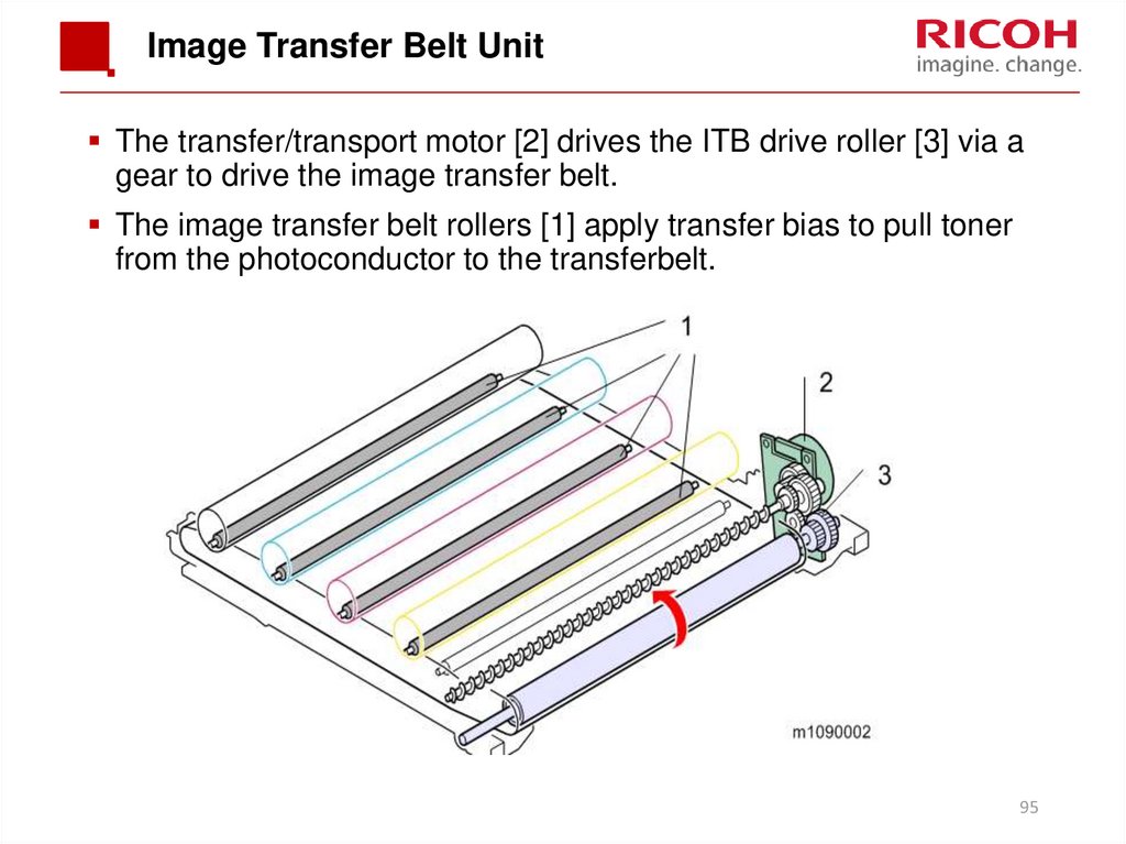
The transfer/transport motor [2] drives the ITB drive roller [3] via agear to drive the image transfer belt.
The image transfer belt rollers [1] apply transfer bias to pull toner
from the photoconductor to the transferbelt.
95
96. Transfer Belt Contact Mechanism
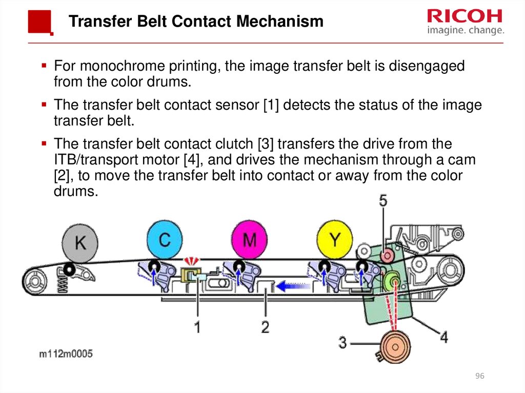
For monochrome printing, the image transfer belt is disengagedfrom the color drums.
The transfer belt contact sensor [1] detects the status of the image
transfer belt.
The transfer belt contact clutch [3] transfers the drive from the
ITB/transport motor [4], and drives the mechanism through a cam
[2], to move the transfer belt into contact or away from the color
drums.
96
97. Belt Guide Roller
In previous models, this roller [5] was inside the ITB unit. However,for this machine, there is no room inside the unit, so it is added at
the location shown above.
This roller keeps the belt under tension, and prevents the belt from
moving to the left or right on the axis of the drive roller.
97
98. Transfer Belt Cleaning
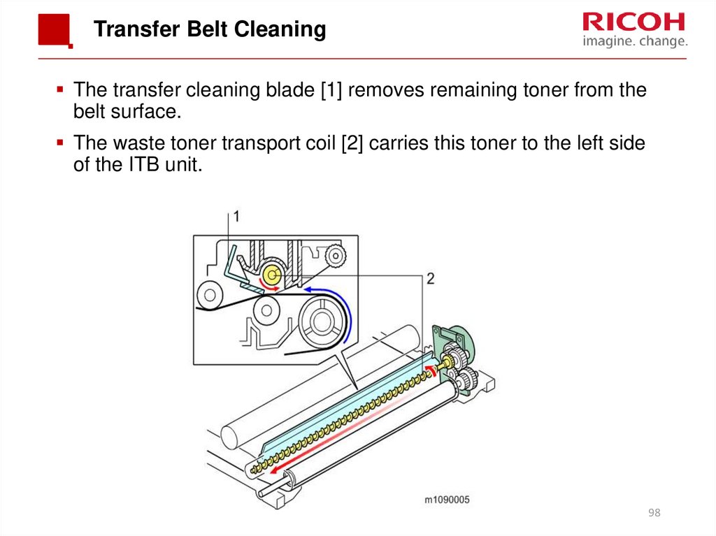
The transfer cleaning blade [1] removes remaining toner from thebelt surface.
The waste toner transport coil [2] carries this toner to the left side
of the ITB unit.
98
99. Paper Transfer Roller Unit
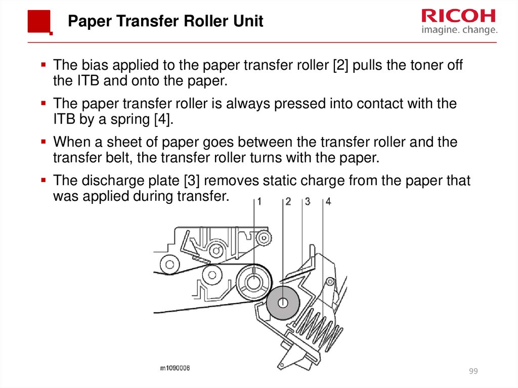
The bias applied to the paper transfer roller [2] pulls the toner offthe ITB and onto the paper.
The paper transfer roller is always pressed into contact with the
ITB by a spring [4].
When a sheet of paper goes between the transfer roller and the
transfer belt, the transfer roller turns with the paper.
The discharge plate [3] removes static charge from the paper that
was applied during transfer.
99
100. Transfer Roller Cleaning
Toner may transfer to the roller surface following a paper jam or ifthe paper is smaller than the image.
Periodic cleaning of the roller is required to prevent this toner from
migrating back to the rear of new printouts.
The machine cleans the roller at the following times:
After initial power on.
After clearing a paper jam
The machine first supplies a negative cleaning current (about -4
mA) to the transfer roller, causing negatively charged toner on the
roller to move back to the transfer belt. It then applies a positive
cleaning current (+5 mA) to the roller, causing any positively
charged toner to migrate back to the transfer belt.
100
101. Paper Separation
During paper transfer, the transfer roller [A] applies a static chargeto the paper [B].
The discharge plate [C] grounds any remaining static charge after
passing the transfer roller unit.
101
102. New ITB Unit Detection
The ITB new unit detection mechanism is not present in theservice part.
It is only in the supplied part that is installed by the user.
When a technician replaces this part, the PM counter for this part
must also be reset (see a later slide for more information).
When the machine detects an unbroken fuse [1] immediately after
the ITB unit is installed, the machine blows the fuse, and resets
the life counter for the ITB and for the paper transfer roller.
However, if the only one of the parts is changed, counters must be
reset as explained later in this part of the course.
102
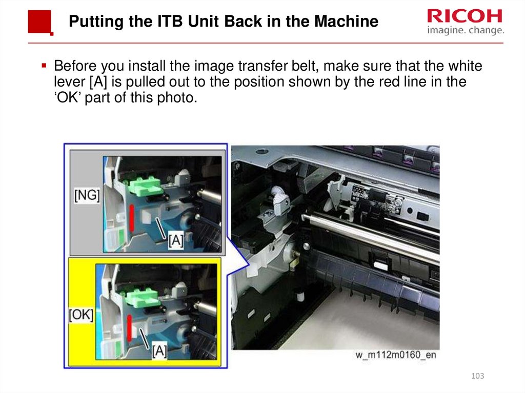
103. Putting the ITB Unit Back in the Machine
Before you install the image transfer belt, make sure that the whitelever [A] is pulled out to the position shown by the red line in the
‘OK’ part of this photo.
103
104. Installing a New ITB Unit
Print out the logging data using SP5-990-004 before you replacethe part.
The counter for the Image Transfer Belt Unit must be reset after
installing a new one.
Execute SP7-804-017 and SP7-804-060
Turn off the power of the machine, and then turn it back on.
This only applies to parts installed by service technicians.
The part for replacement by users has a new unit detection
mechanism (the fuse, as explained earlier).
104
105. Installing a New Paper Transfer Roller
Print out the logging data using SP5-990-004 before you replacethe part.
The counter for the Paper Transfer Roller must be reset after
installing a new one.
Execute SP7-804-022 and SP7-804-061
Turn off the power of the machine, and then turn it back on.
This only applies to replacement by service technicians.
The Paper Transfer Roller as a supply part is in the same kit as
the Image Transfer Belt unit and does not require counter reset,
because it will be replaced at the same time as the Image Transfer
Belt Unit.
105
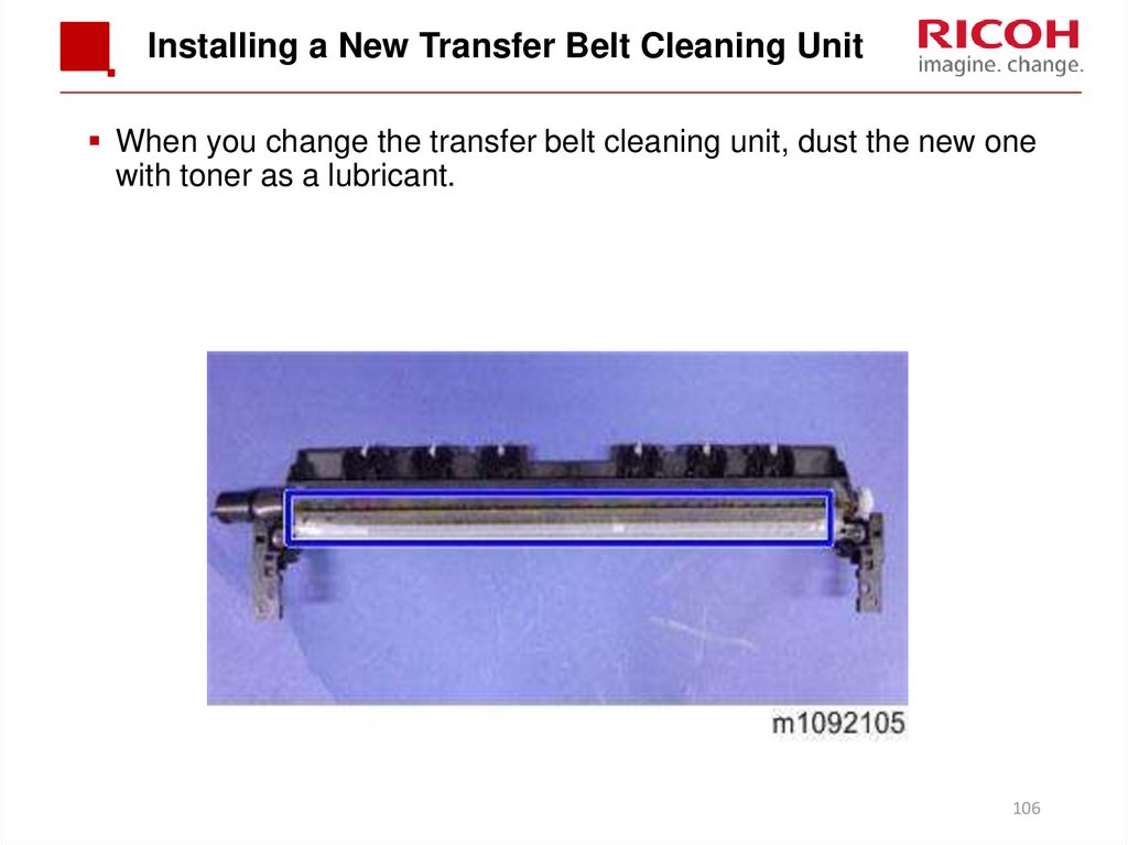
106. Installing a New Transfer Belt Cleaning Unit
When you change the transfer belt cleaning unit, dust the new onewith toner as a lubricant.
106
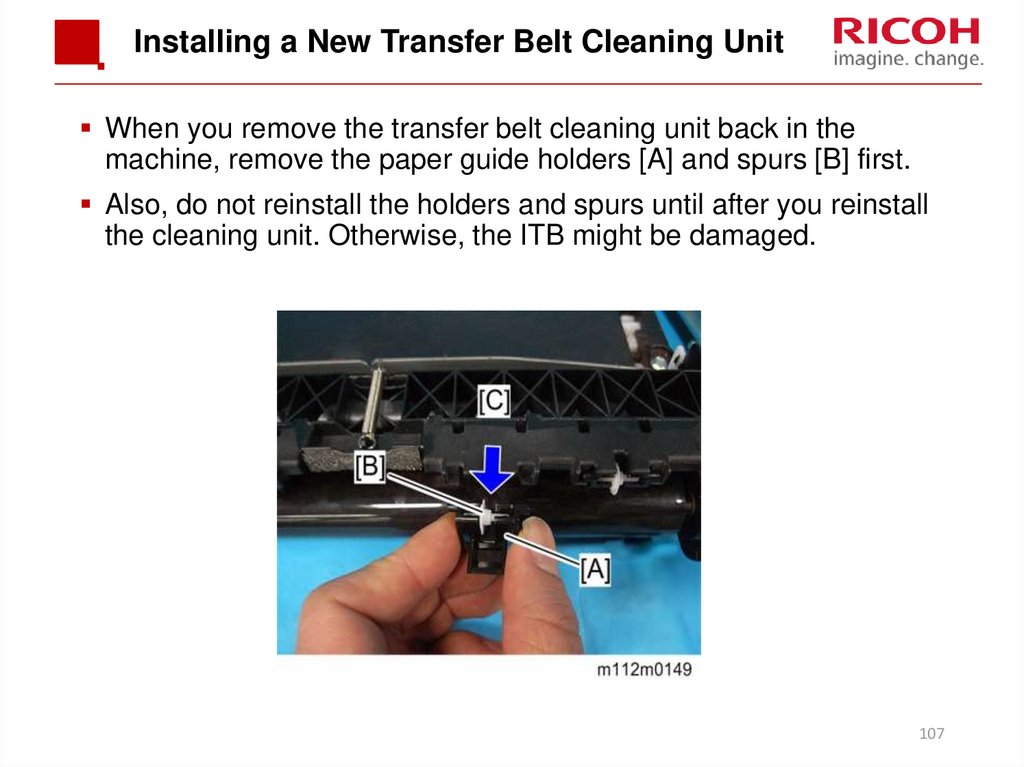
107. Installing a New Transfer Belt Cleaning Unit
When you remove the transfer belt cleaning unit back in themachine, remove the paper guide holders [A] and spurs [B] first.
Also, do not reinstall the holders and spurs until after you reinstall
the cleaning unit. Otherwise, the ITB might be damaged.
107
108.
Fusing108
109. Overview
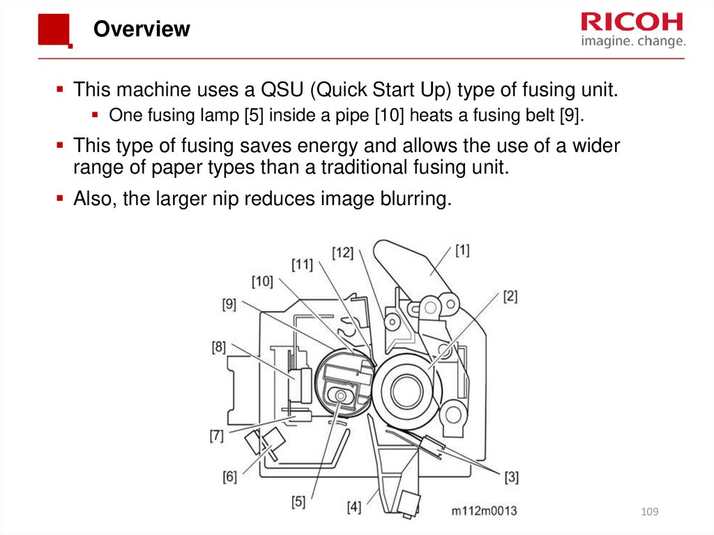
This machine uses a QSU (Quick Start Up) type of fusing unit.One fusing lamp [5] inside a pipe [10] heats a fusing belt [9].
This type of fusing saves energy and allows the use of a wider
range of paper types than a traditional fusing unit.
Also, the larger nip reduces image blurring.
109
110. Quick Start-up (QSU) System
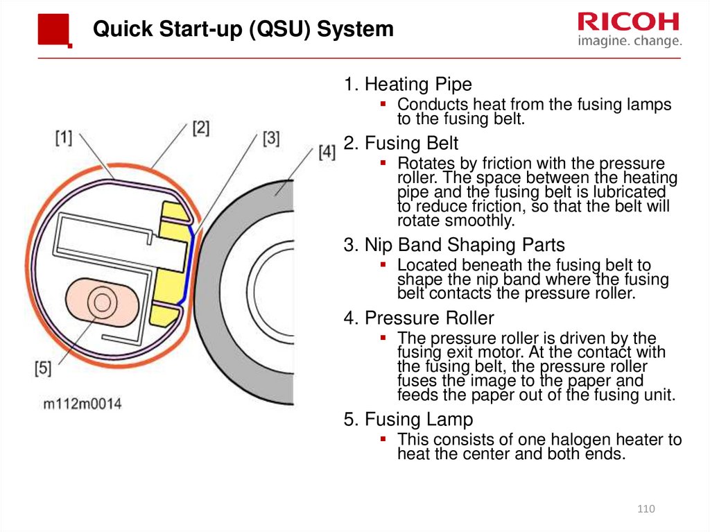
1. Heating PipeConducts heat from the fusing lamps
to the fusing belt.
2. Fusing Belt
Rotates by friction with the pressure
roller. The space between the heating
pipe and the fusing belt is lubricated
to reduce friction, so that the belt will
rotate smoothly.
3. Nip Band Shaping Parts
Located beneath the fusing belt to
shape the nip band where the fusing
belt contacts the pressure roller.
4. Pressure Roller
The pressure roller is driven by the
fusing exit motor. At the contact with
the fusing belt, the pressure roller
fuses the image to the paper and
feeds the paper out of the fusing unit.
5. Fusing Lamp
This consists of one halogen heater to
heat the center and both ends.
110
111. Fusing Unit Drive
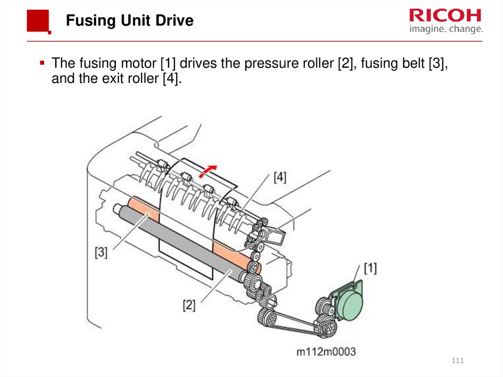
The fusing motor [1] drives the pressure roller [2], fusing belt [3],and the exit roller [4].
111
112. New Unit Detection
This is done using a fuse [2] on the rear frame [3] of the fusing unit.[1] is the fusing unit drawer.
There is no service part; the technician uses the same part as the
user PM kit to replace the fusing unit.
So there is no counter to reset.
112
113. Pressure Release
A pressure release mechanism makes it easy to remove paperjams in the fusing unit.
The pressure lever is released when the front cover opens, and
the pressure roller separates from the fusing belt due to a spring.
113
114. Fusing Temperature Control
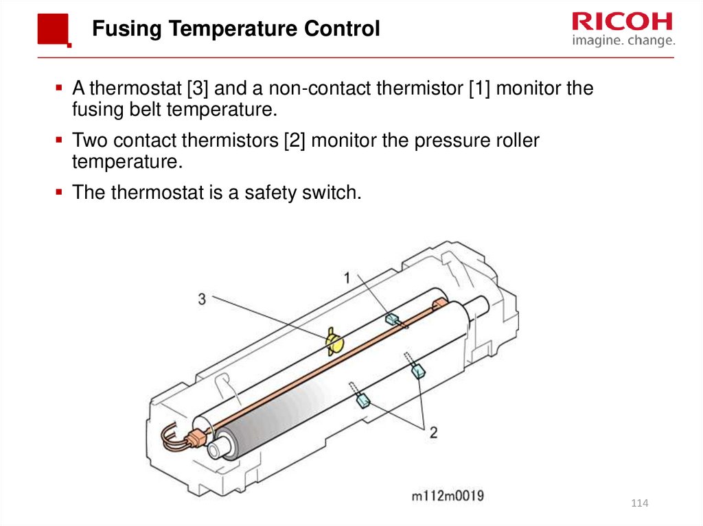
A thermostat [3] and a non-contact thermistor [1] monitor thefusing belt temperature.
Two contact thermistors [2] monitor the pressure roller
temperature.
The thermostat is a safety switch.
114
115. Fusing Temperature Control Warming-up Mode
Fusing warm-up begins after the machine power is switched on.The fusing lamp heats without roller rotation until the temperature
reaches the “pre-rotation start temp.”
There is no roller rotation, in order to heat the lubricant between the
heating pipe and the fusing belt so that the pressure roller rotation
will move the belt.
Then, the fusing motor turns on, until the fusing temperature
reaches the “start-up temperature” (also called the “reload
temperature”).
115
116. Fusing Temperature Control Print Mode
The fusing temperature increases to the “print ready temperature”,and printing starts.
To reduce energy consumption, the fusing lamps turn off before
the last sheet of paper passes completely through the fusing nip
band.
After printing, the roller continues to turn, to prevent temperature
overshoot after printing.
After a certain time, the mode changes to the wait mode.
116
117. Fusing Temperature Control Wait Mode
The fusing lamp and the fusing motor turn OFF after a certain timepasses after the temperature has fallen to the print ready
temperature.
At regular intervals, the fusing motor rotates for a short time at
slow speed.
The fusing motor stops when the machine is in Sleep Mode.
117
118. Fusing Temperature Control PPM Down Mode
PPM down control changes the feed timing to create a widerinterval between the sheets of paper feeding through the fusing
unit.
This is done in some specific conditions to prevent image
problems.
118
119.
Waste Toner Collection119
120. Overview
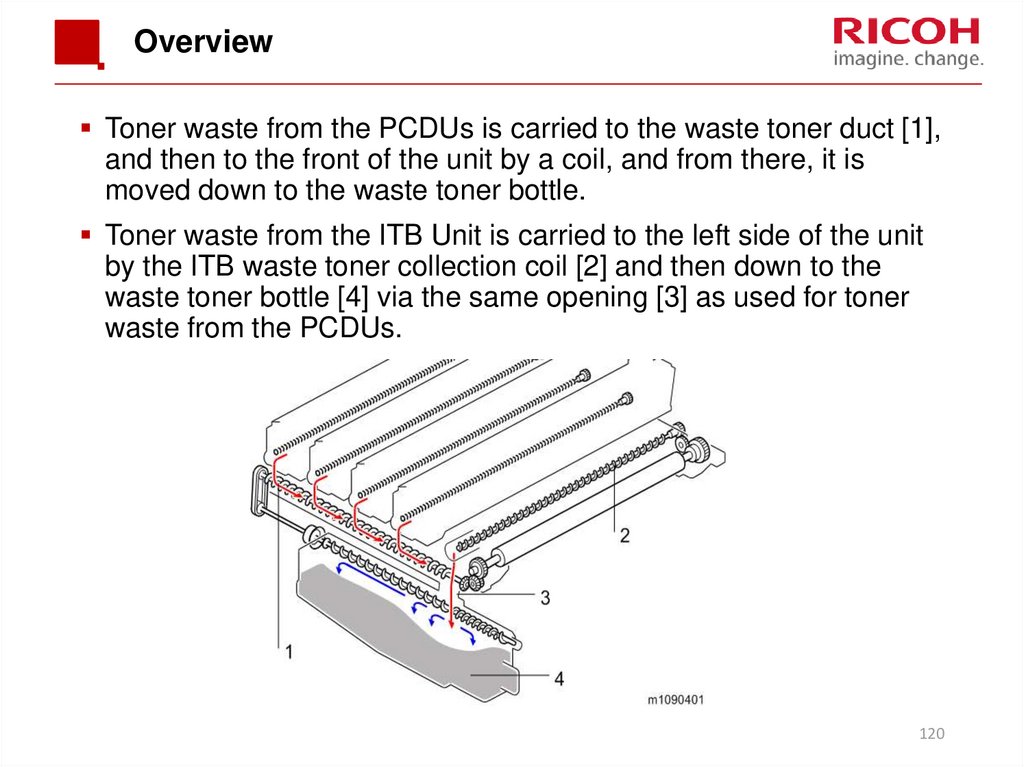
Toner waste from the PCDUs is carried to the waste toner duct [1],and then to the front of the unit by a coil, and from there, it is
moved down to the waste toner bottle.
Toner waste from the ITB Unit is carried to the left side of the unit
by the ITB waste toner collection coil [2] and then down to the
waste toner bottle [4] via the same opening [3] as used for toner
waste from the PCDUs.
120
121. Drive
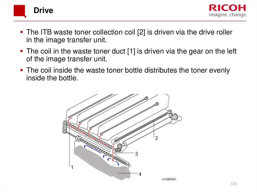
The ITB waste toner collection coil [2] is driven via the drive rollerin the image transfer unit.
The coil in the waste toner duct [1] is driven via the gear on the left
of the image transfer unit.
The coil inside the waste toner bottle distributes the toner evenly
inside the bottle.
121
122. Waste Toner Bottle Set Sensor (1/2)
The waste toner bottle set sensor [2] detects the presence of thewaste toner bottle [4].
There is no bottle replacement detection feature. If the bottle full
sensor is off and the bottle set sensor is on, the machine indicates
that the waste toner bottle is usable.
122
123. Waste Toner Bottle Full Sensor (2/2)
When waste toner exceeds a certain amount, the rubber portionon the inner part of the waste toner bottle swells.
This exerts pressure on the feeler [1], and the waste toner bottle
full sensor [3] is turned on.
At this time, the machine detects that the bottle is nearly full.
After the bottle is detected to be nearly full, the machine uses a
pixel count to detect when the waste toner bottle is full.
The required pixel count between near-full and full can be
adjusted with an SP3-800-017 or a User Tool.
123
124. Toner Bottle Full
The pixel count corresponds to a number of sheets that can beprinted after indicating near full.
However, these are reference values based on certain specified
machine use conditions.
Normal: 475 pages
Notify Later: 285 pages
Notify Sooner: 665 pages
The default is Normal. Users can change with a user tool.
Maintenance > General Settings > Replacement Alert:
124
125. Lubricant
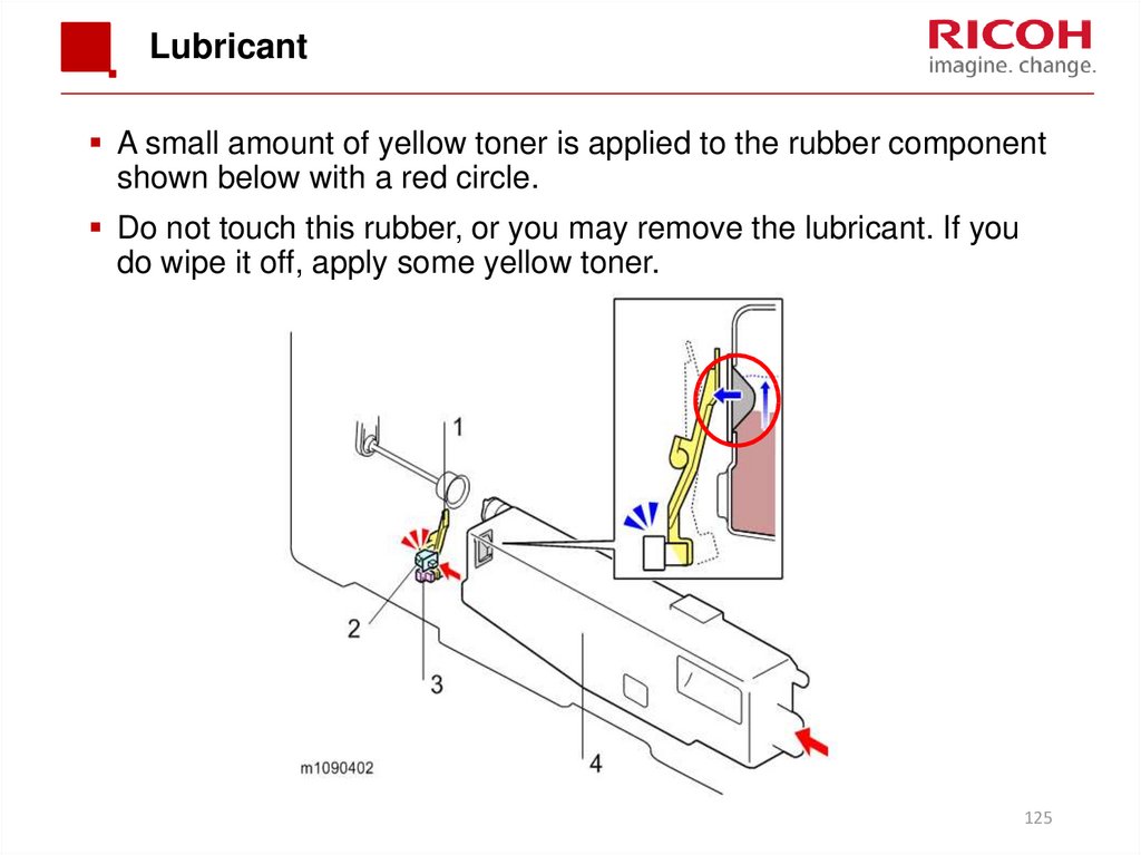
A small amount of yellow toner is applied to the rubber componentshown below with a red circle.
Do not touch this rubber, or you may remove the lubricant. If you
do wipe it off, apply some yellow toner.
125
126. Replacement
Either the customer or the technician can replace the tonercollection bottle.
The counter for the pixel count resets automatically.
Attach the waste toner bottle with the left cover installed.
If not, the waste toner bottle is not positioned accurately, which may
cause clogging of waste toner, because the lid between the waste
toner duct and the waste toner bottle may not open.
126
127.
Process Control127
128. Processes
Process controlDevelopment bias control
Toner supply control
MUSIC
The toner mark sensors (TM (ID) sensors) read patches made on the
ITB, and the machine corrects color image registration based on the
sensor readings.
The patches are made on the left and right of the ITB.
MUSIC is done automatically at specific times.
IBACC (Image transfer Belt ACC)
IBACC does halftone correction by detecting the density of a
gradation patch formed on the Image Transfer Belt.
While conventional ACC (Auto Color Calibration) prints a test chart
and feeds back the density detected by the scanner, IBACC does all
the operations inside the printer.
The TM (ID) sensors are used for this function.
IBACC can be executed by the user at any time, using the Auto Color
Calibration function. At this time, MUSIC is done, then process
control, then IBACC.
128
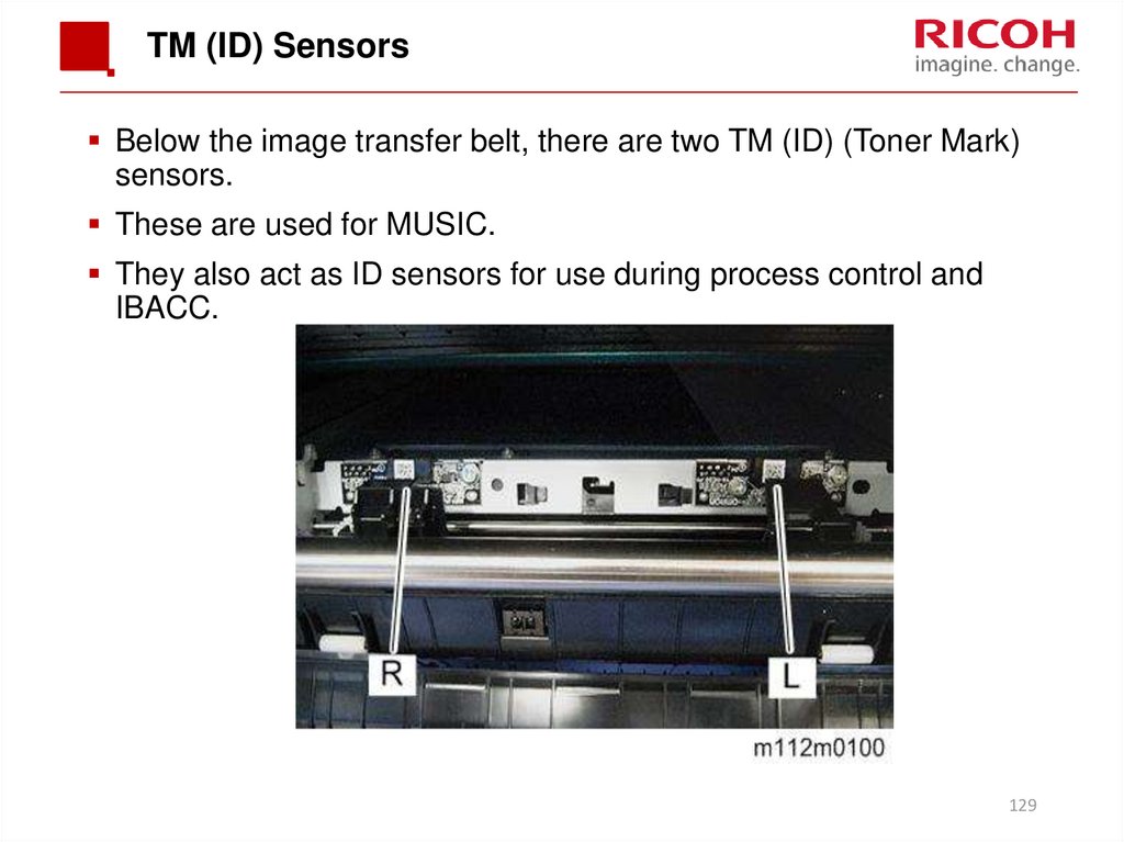
129. TM (ID) Sensors
Below the image transfer belt, there are two TM (ID) (Toner Mark)sensors.
These are used for MUSIC.
They also act as ID sensors for use during process control and
IBACC.
129
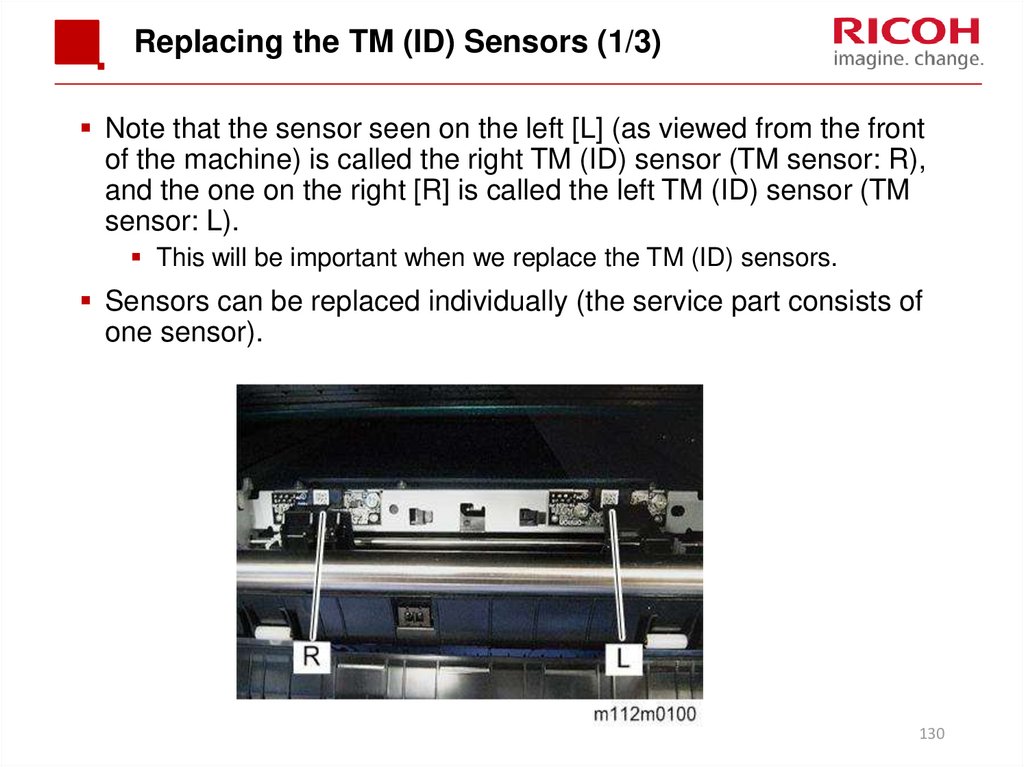
130. Replacing the TM (ID) Sensors (1/3)
Note that the sensor seen on the left [L] (as viewed from the frontof the machine) is called the right TM (ID) sensor (TM sensor: R),
and the one on the right [R] is called the left TM (ID) sensor (TM
sensor: L).
This will be important when we replace the TM (ID) sensors.
Sensors can be replaced individually (the service part consists of
one sensor).
130
131. Replacing the TM (ID) Sensors (2/3)
Before replacement:Each sensor has a label with some numbers on it [A].
These numbers must be input into SP mode before you turn off the
power and replace the old TM (ID) sensor.
As you look from the front of the machine:
The sensor on the left is TM (ID) sensor: R. These values must
be input into SP 3-333.
The sensor on the right is TM (ID) sensor: L. These values must
be input into SP 3-334.
After this, there are some other SP settings to initialize before
replacement.
See the procedure in the service manual for details.
131
132. Replacing the TM (ID) Sensors (3/3)
After replacement:Execute SP3-011-004 (Adjustment manual exe. Full Music / process
control)
If there is something wrong with the image after SP execution, make
sure that input values are registered in the correct SP-modes.
132
133. Paper Exit
MF Model:To prevent of a early Tray full detection, caused by paper that hits the
scanner unit, the feeler is changed to a moveable type.
Printer
MF
133


















 Электроника


