


 Механика
Похожие презентации:


Mechanics of Material
1.
Mechanics of MaterialChapter II
Stress and Strain – Axial Loading
1
2.
Stress and StrainContents
Stress & Strain: Axial Loading
Normal Strain
Stress-Strain Test
Stress-Strain Diagram: Ductile Materials
Stress-Strain Diagram: Brittle Materials
Hooke’s Law: Modulus of Elasticity
Elastic vs. Plastic Behavior
Fatigue
Deformations Under Axial Loading
Example 2.01
Sample Problem 2.1
Static Indeterminacy
Example 2.04
Thermal Stresses
Poisson’s Ratio
2
Generalized Hooke’s Law
Dilatation: Bulk Modulus
Shearing Strain
Example 2.10
Relation Among E, n, and G
Sample Problem 2.5
Composite Materials
Saint-Venant’s Principle
Stress Concentration: Hole
Stress Concentration: Fillet
Example 2.12
Elastoplastic Materials
Plastic Deformations
Residual Stresses
Example 2.14, 2.15, 2.16
3.
Stress and StrainAxial loading
• Suitability of a structure or machine may depend on the
deformations in the structure as well as the stresses induced
under loading. Statics analyses alone are not sufficient.
• Considering structures as deformable allows determination of
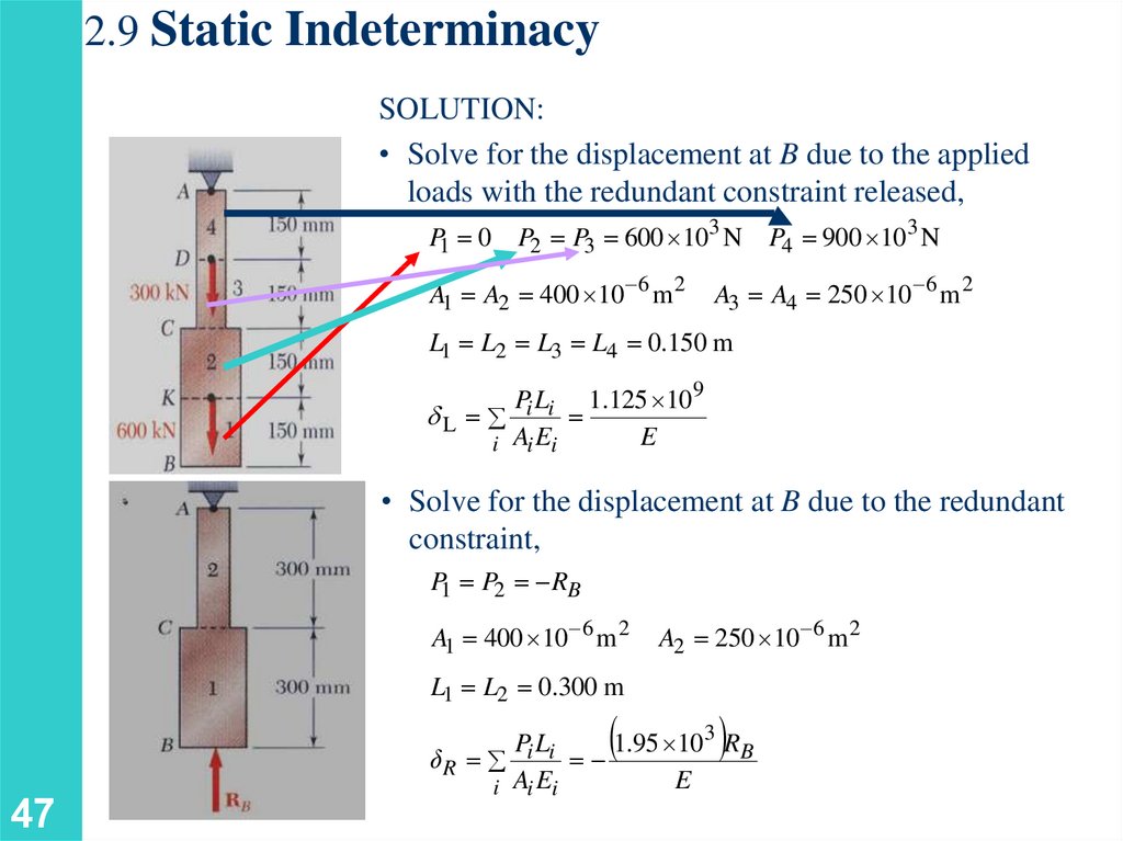
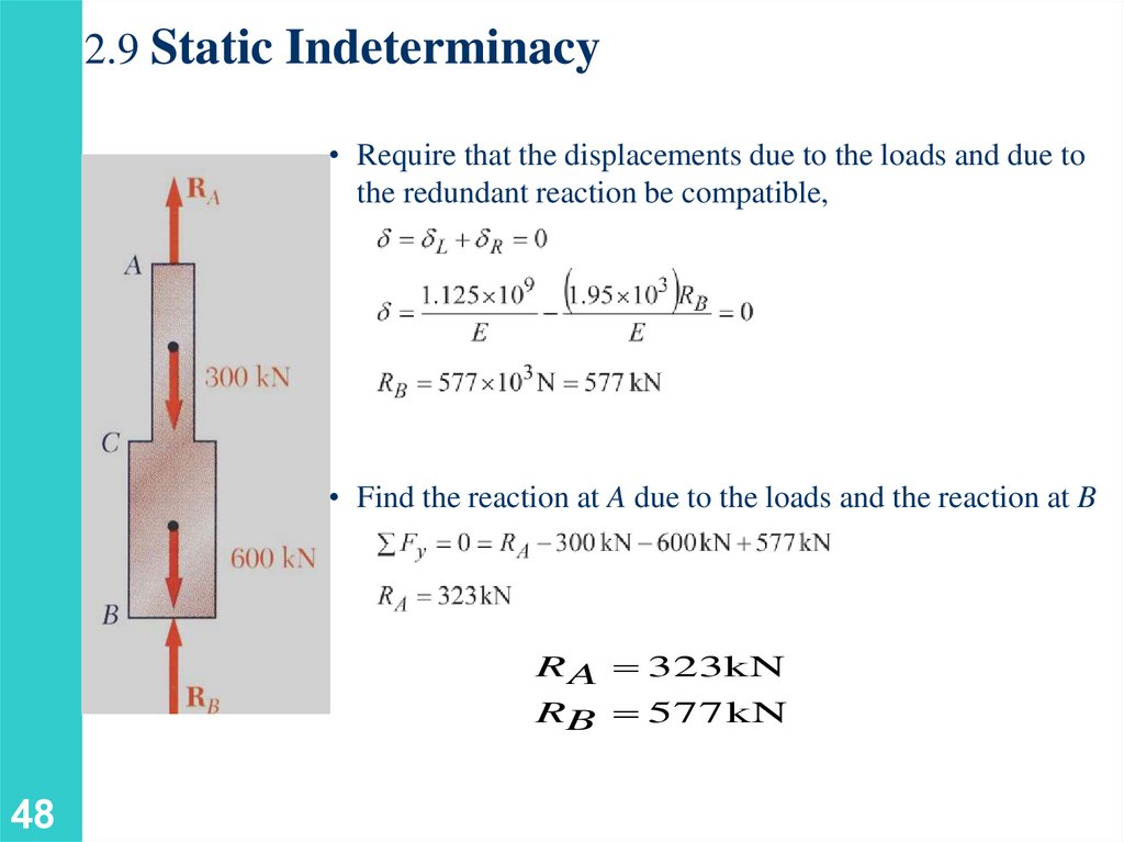
member forces and reactions which are statically
indeterminate.
• Determination of the stress distribution within a member also
requires consideration of deformations in the member.
3
4.
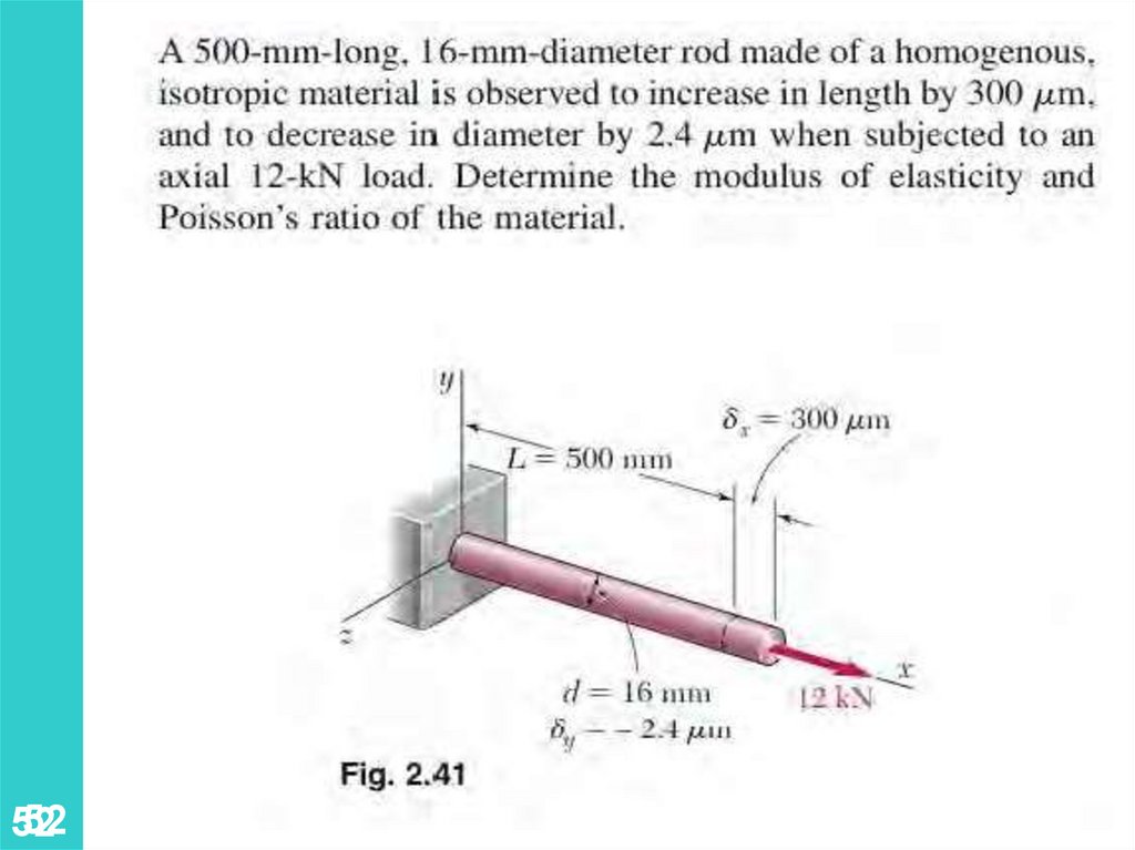
DisplacementMovement of a point w.r.t. a reference system. Maybe
caused by translation and or rotation of object (rigid
body). Change in shape or size related to displacements
are called deformations. Change in linear dimension
causes deformation d
44
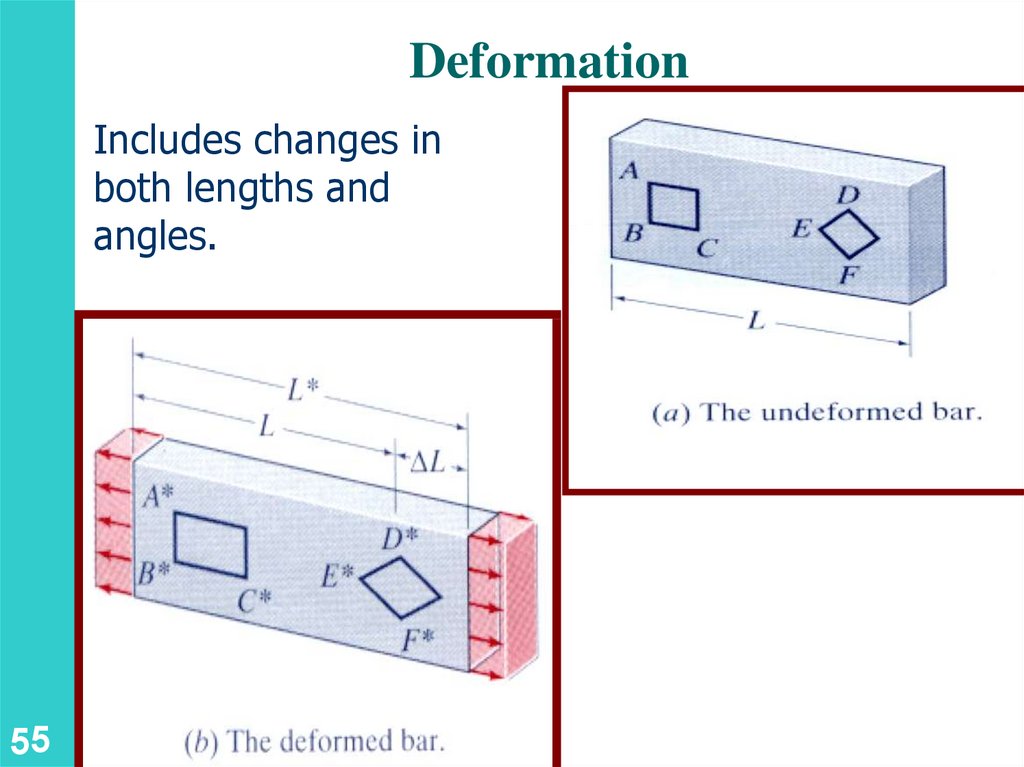
5.
DeformationIncludes changes in
both lengths and
angles.
55
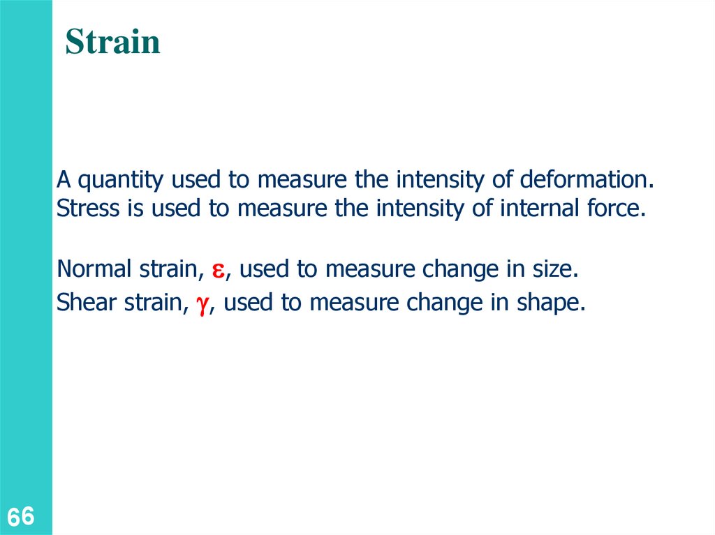
6.
StrainA quantity used to measure the intensity of deformation.
Stress is used to measure the intensity of internal force.
Normal strain, e, used to measure change in size.
Shear strain, g, used to measure change in shape.
66
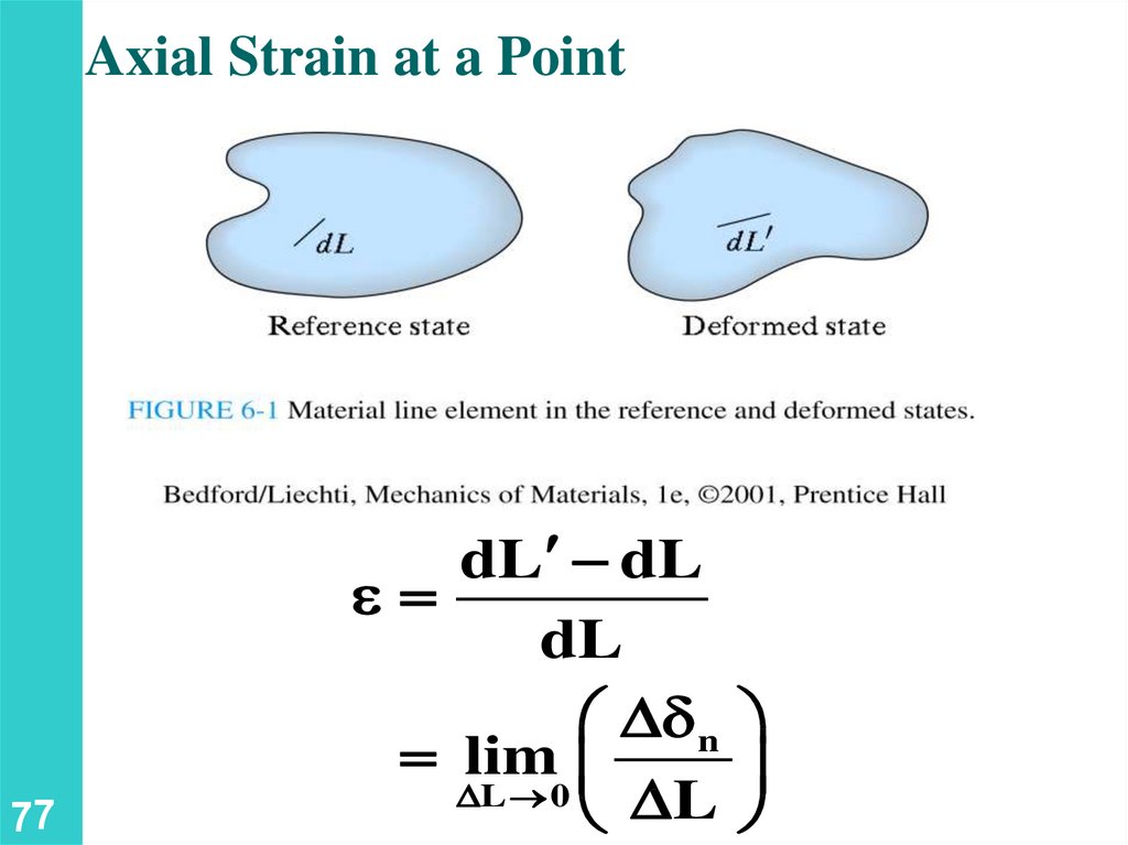
7.
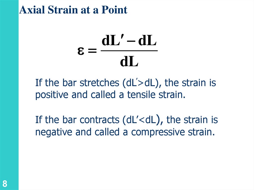
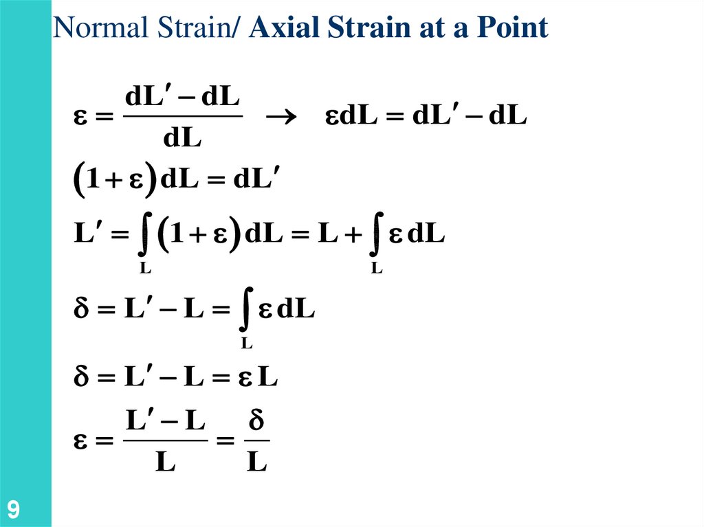
Axial Strain at a Point77
dL dL
e
dL
d n
lim
L 0
L
8.
Axial Strain at a PointdL dL
e
dL
If the bar stretches (dL’>dL), the strain is
positive and called a tensile strain.
If the bar contracts (dL’<dL), the strain is
negative and called a compressive strain.
8
9.
Normal Strain/ Axial Strain at a PointdL dL
e
edL dL dL
dL
1 e dL dL
L
1 e dL L e dL
L
L
d L L e dL
L
d L L e L
L L d
e
L
L
9
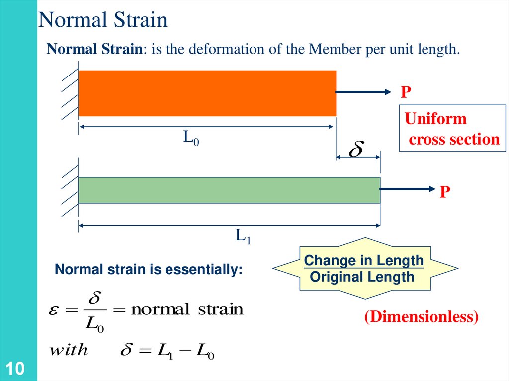
10.
Normal StrainNormal Strain: is the deformation of the Member per unit length.
P
L0
d
Uniform
cross section
P
L1
Normal strain is essentially:
e
10
d
L0
with
normal strain
d L1 L0
Change in Length
Original Length
(Dimensionless)
11.
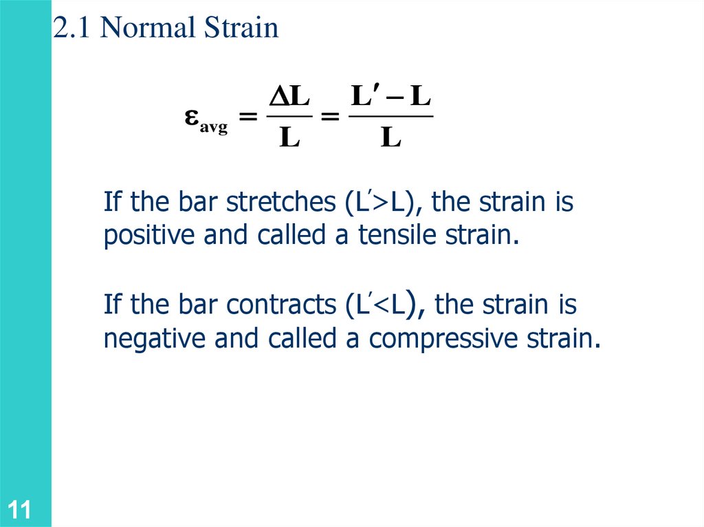
2.1 Normal Straineavg
L L L
L
L
If the bar stretches (L’>L), the strain is
positive and called a tensile strain.
If the bar contracts (L’<L), the strain is
negative and called a compressive strain.
11
12.
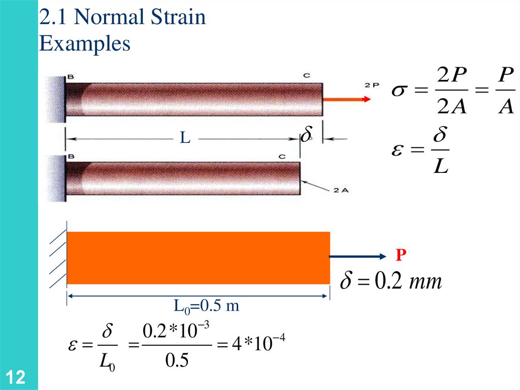
2.1 Normal StrainExamples
L
d
2P P
2A A
e
P
d
L
d 0.2 mm
L0=0.5 m
12
d 0.2 *10 3
4
e
4 *10
L0
0.5
13.
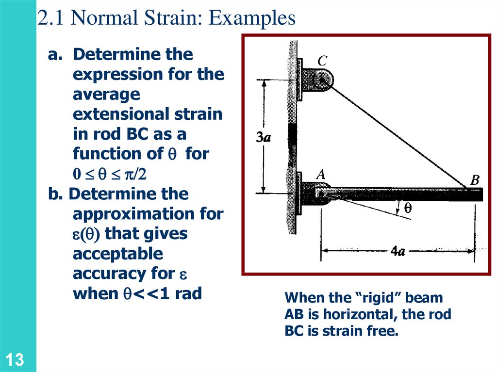
2.1 Normal Strain: Examplesa. Determine the
expression for the
average
extensional strain
in rod BC as a
function of q for
0 q p/2
b. Determine the
approximation for
e q that gives
acceptable
accuracy for e
when q<<1 rad
13
When the “rigid” beam
AB is horizontal, the rod
BC is strain free.
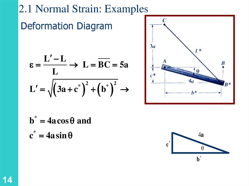
14.
2.1 Normal Strain: ExamplesDeformation Diagram
L L
e
L BC 5a
L
L
3a c b
*
2
*
2
b* 4a cos q and
c* 4a sin q
4a
c*
θ
b*
14
15.
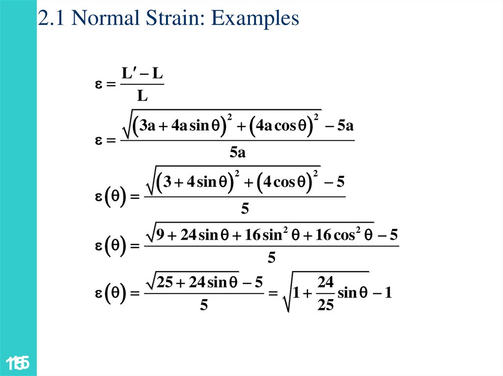
2.1 Normal Strain: ExamplesL L
e
L
3a 4a sin q 4a cos q 5a
2
e
e q
15
15
2
5a
3 4 sin q
2
4 cos q 5
2
5
e q
9 24 sin q 16 sin 2 q 16 cos 2 q 5
5
e q
25 24 sin q 5
24
1
sin q 1
5
25
16.
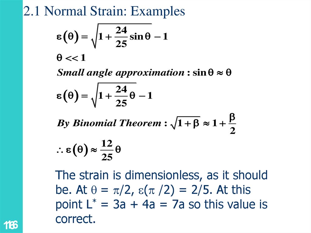
2.1 Normal Strain: Examplese q
24
1
sin q 1
25
q 1
Small angle approximation : sin q q
e q
24
1
q 1
25
By Binomial Theorem : 1 1
2
12
e q
q
25
16
16
The strain is dimensionless, as it should
be. At q = p/2, e(p /2) = 2/5. At this
point L* = 3a + 4a = 7a so this value is
correct.
17.
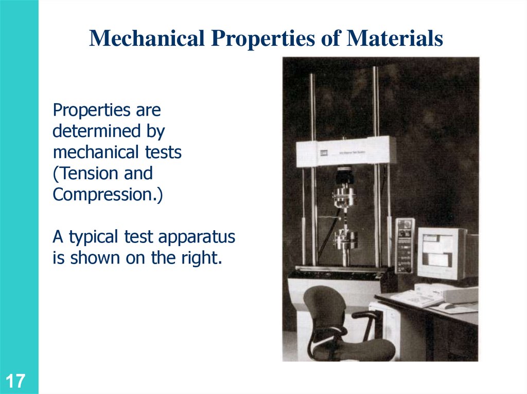
Mechanical Properties of MaterialsProperties are
determined by
mechanical tests
(Tension and
Compression.)
A typical test apparatus
is shown on the right.
17
18.
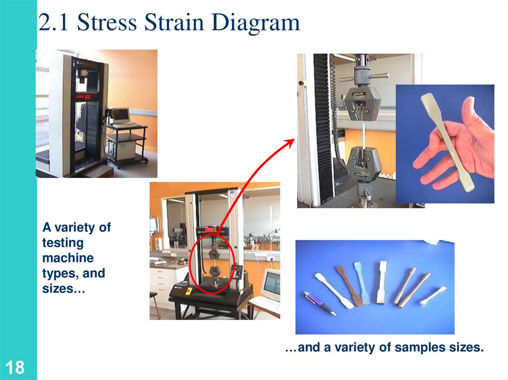
2.1 Stress Strain DiagramA variety of
testing
machine
types, and
sizes…
…and a variety of samples sizes.
18
19.
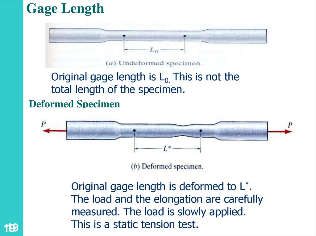
Gage LengthOriginal gage length is L0. This is not the
total length of the specimen.
Deformed Specimen
19
19
Original gage length is deformed to L*.
The load and the elongation are carefully
measured. The load is slowly applied.
This is a static tension test.
20.
2.1 Stress Strain DiagramA plot of stress versus strain is called a stress strain
diagram. From this diagram we can find a number
of important mechanical properties.
P
A
dn
e
L
20
e
21.
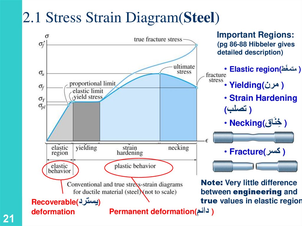
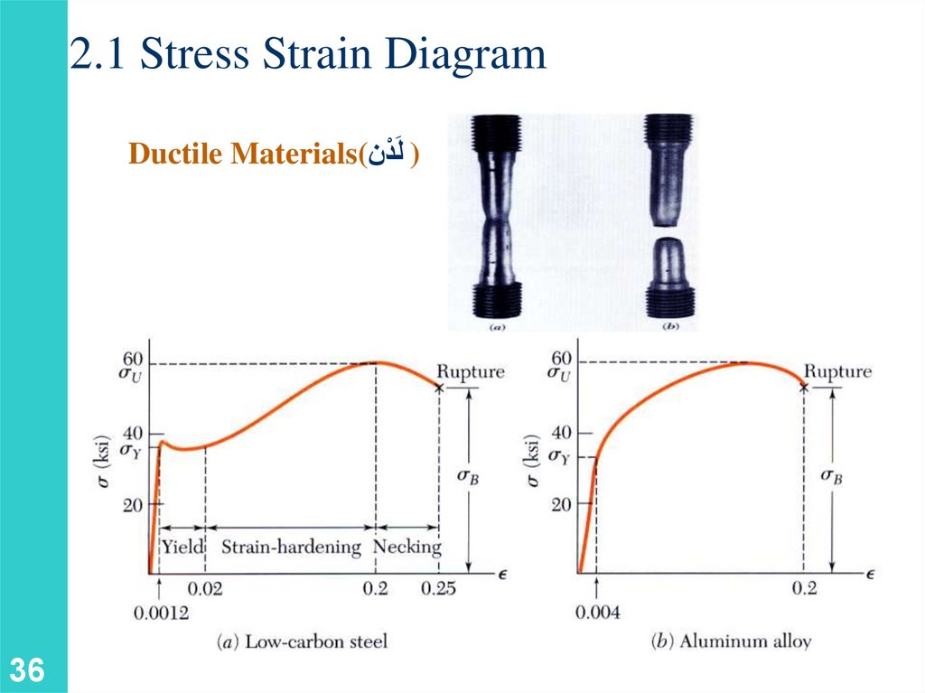
2.1 Stress Strain Diagram(Steel)Important Regions:
(pg 86-88 Hibbeler gives
detailed description)
• Elastic region() متمغّط
• Yielding() مرن
• Strain Hardening
() تصلب
• Necking() ِخنَاق
• Fracture() كسر
21
Recoverable()يسترد
deformation
Note: Very little difference
between engineering and
true values in elastic region
Permanent deformation() دائم
22.
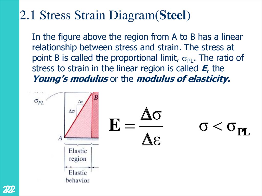
2.1 Stress Strain Diagram(Steel)In the figure above the region from A to B has a linear
relationship between stress and strain. The stress at
point B is called the proportional limit, PL. The ratio of
stress to strain in the linear region is called E, the
Young’s modulus or the modulus of elasticity.
σ
E
ε
22
22
σ σ PL
23.
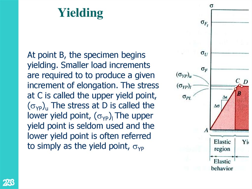
YieldingAt point B, the specimen begins
yielding. Smaller load increments
are required to to produce a given
increment of elongation. The stress
at C is called the upper yield point,
( YP)u The stress at D is called the
lower yield point, ( YP)l The upper
yield point is seldom used and the
lower yield point is often referred
to simply as the yield point, YP
23
23
24.
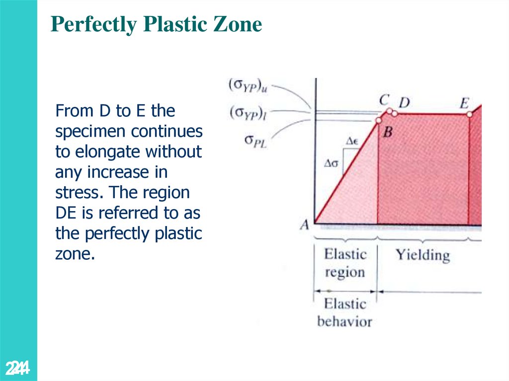
Perfectly Plastic ZoneFrom D to E the
specimen continues
to elongate without
any increase in
stress. The region
DE is referred to as
the perfectly plastic
zone.
24
24
25.
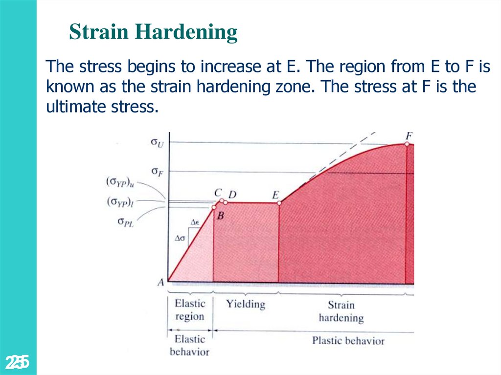
Strain HardeningThe stress begins to increase at E. The region from E to F is
known as the strain hardening zone. The stress at F is the
ultimate stress.
25
25
26.
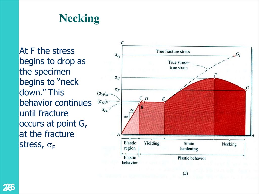
NeckingAt F the stress
begins to drop as
the specimen
begins to “neck
down.” This
behavior continues
until fracture
occurs at point G,
at the fracture
stress, F
26
26
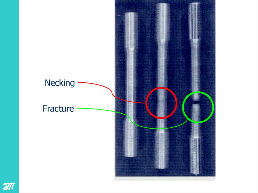
27.
NeckingFracture
27
27
28.
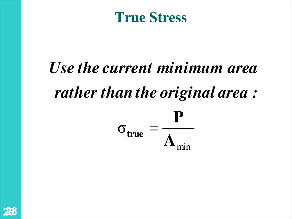
True StressUse the current minimum area
rather than the original area :
σ true
28
28
P
A min
29.
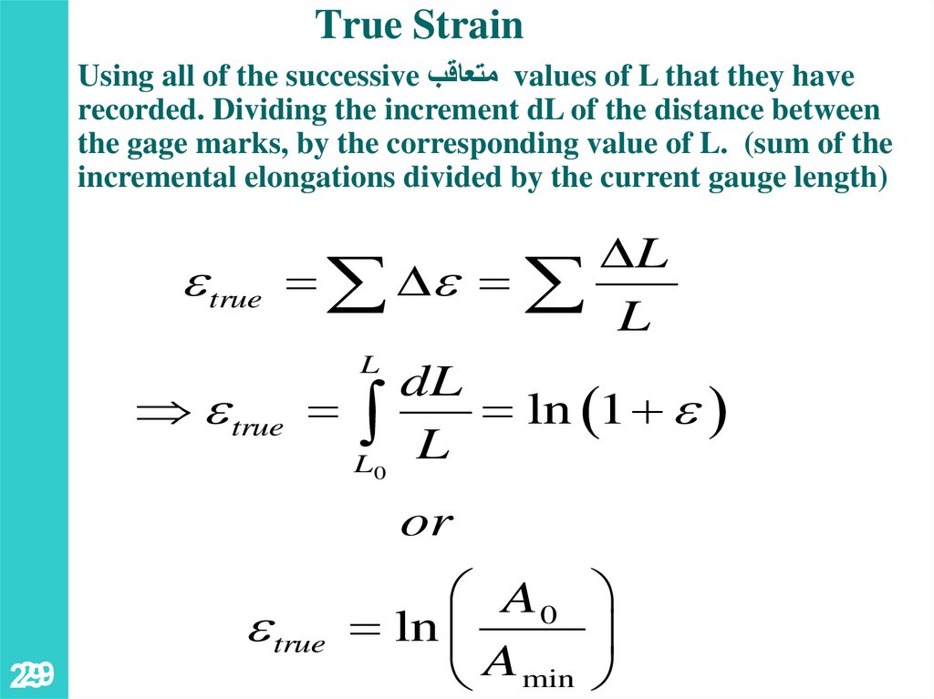
True StrainUsing all of the successive متعاقبvalues of L that they have
recorded. Dividing the increment dL of the distance between
the gage marks, by the corresponding value of L. (sum of the
incremental elongations divided by the current gauge length)
L
e true e
L
L
dL
e true
ln 1 e
L
L0
or
29
29
e true
A0
ln
A min
30.
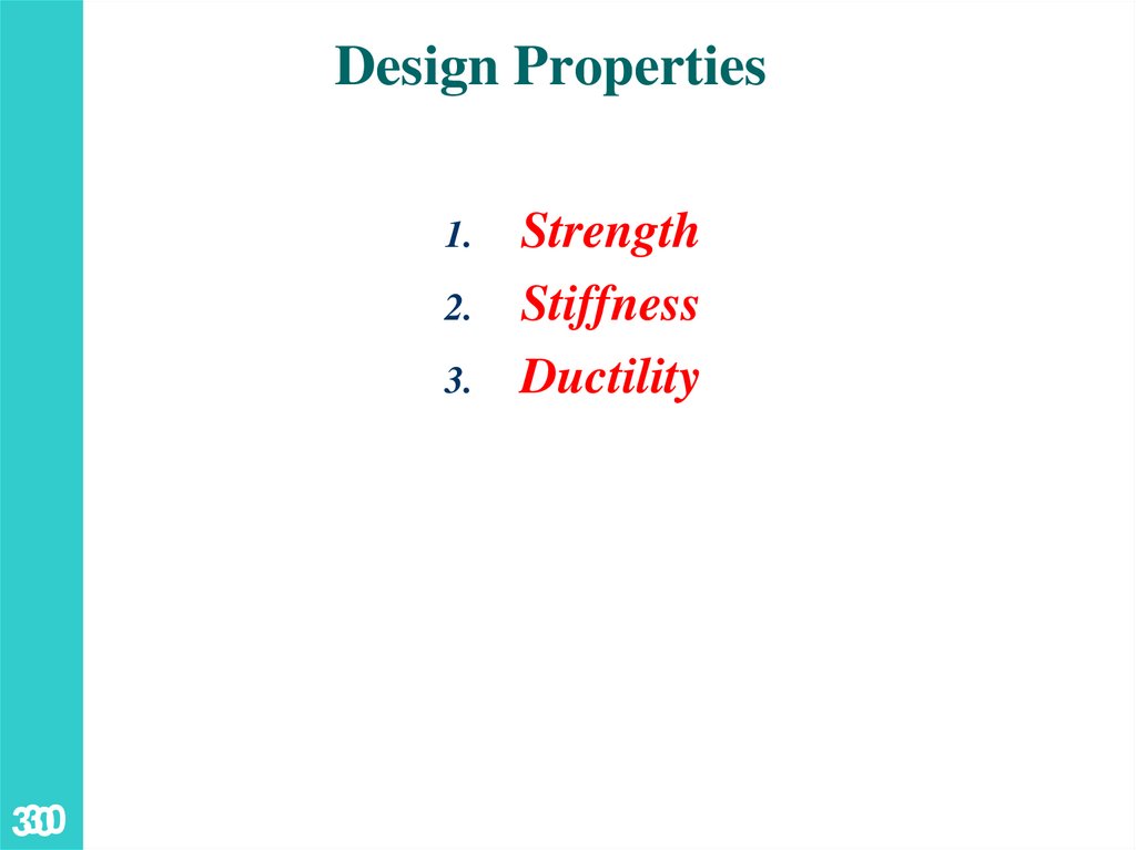
Design Properties1.
2.
3.
30
30
Strength
Stiffness
Ductility
31.
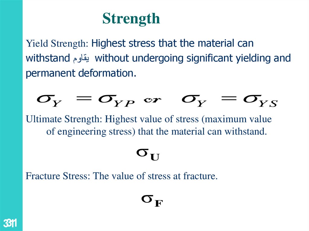
StrengthYield Strength: Highest stress that the material can
withstand يقاومwithout undergoing significant yielding and
permanent deformation.
Y Y P or Y Y S
Ultimate Strength: Highest value of stress (maximum value
of engineering stress) that the material can withstand.
σU
Fracture Stress: The value of stress at fracture.
σF
31
31
32.
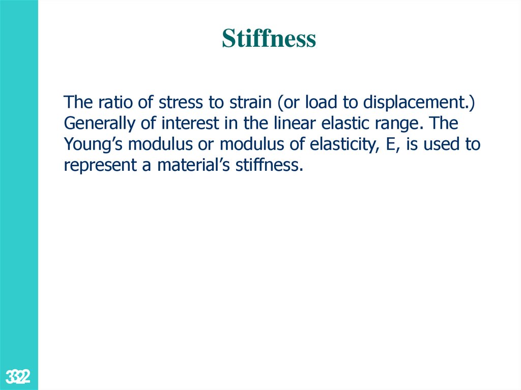
StiffnessThe ratio of stress to strain (or load to displacement.)
Generally of interest in the linear elastic range. The
Young’s modulus or modulus of elasticity, E, is used to
represent a material’s stiffness.
32
32
33.
Ductility تمدد33
33
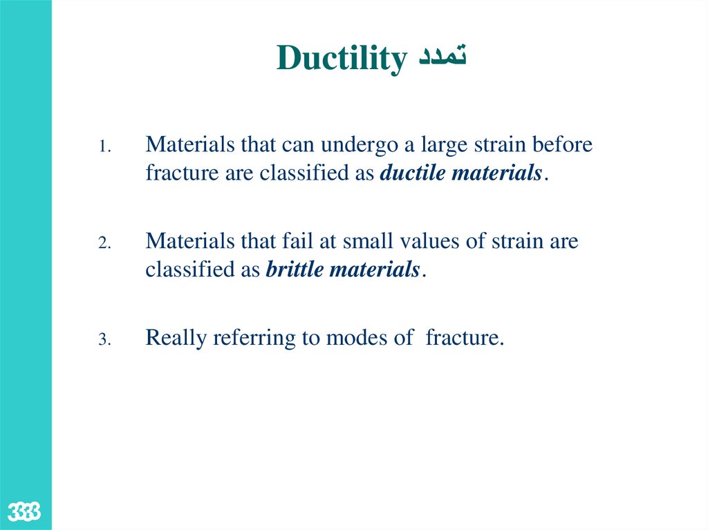
1.
Materials that can undergo a large strain before
fracture are classified as ductile materials.
2.
Materials that fail at small values of strain are
classified as brittle materials.
3.
Really referring to modes of fracture.
34.
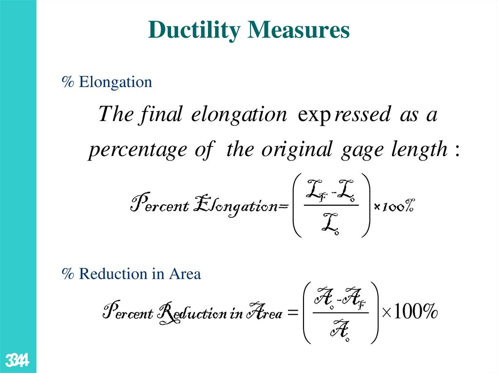
Ductility Measures% Elongation
The final elongation exp ressed as a
percentage of the original gage length :
LF -L0
Percent Elongation=
L0
% Reduction in Area
×100%
A0 -AF
Percent Reduction in Area
A0
34
34
100%
35.
Ductile Materials1.
2.
3.
4.
5.
6.
35
35
Steel
Brass
Aluminum
Copper
Nickel
Nylon
36.
2.1 Stress Strain DiagramDuctile Materials() لَدْن
36
37.
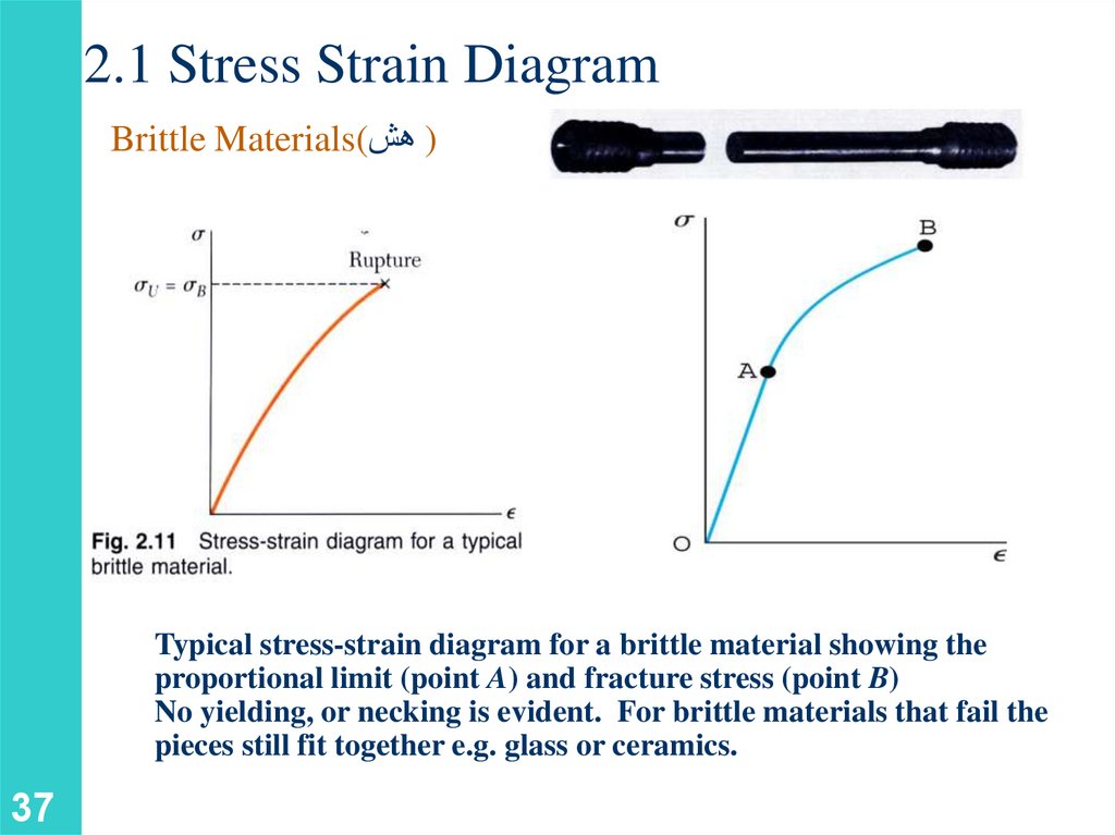
2.1 Stress Strain DiagramBrittle Materials() هش
Typical stress-strain diagram for a brittle material showing the
proportional limit (point A) and fracture stress (point B)
No yielding, or necking is evident. For brittle materials that fail the
pieces still fit together e.g. glass or ceramics.
37
38.
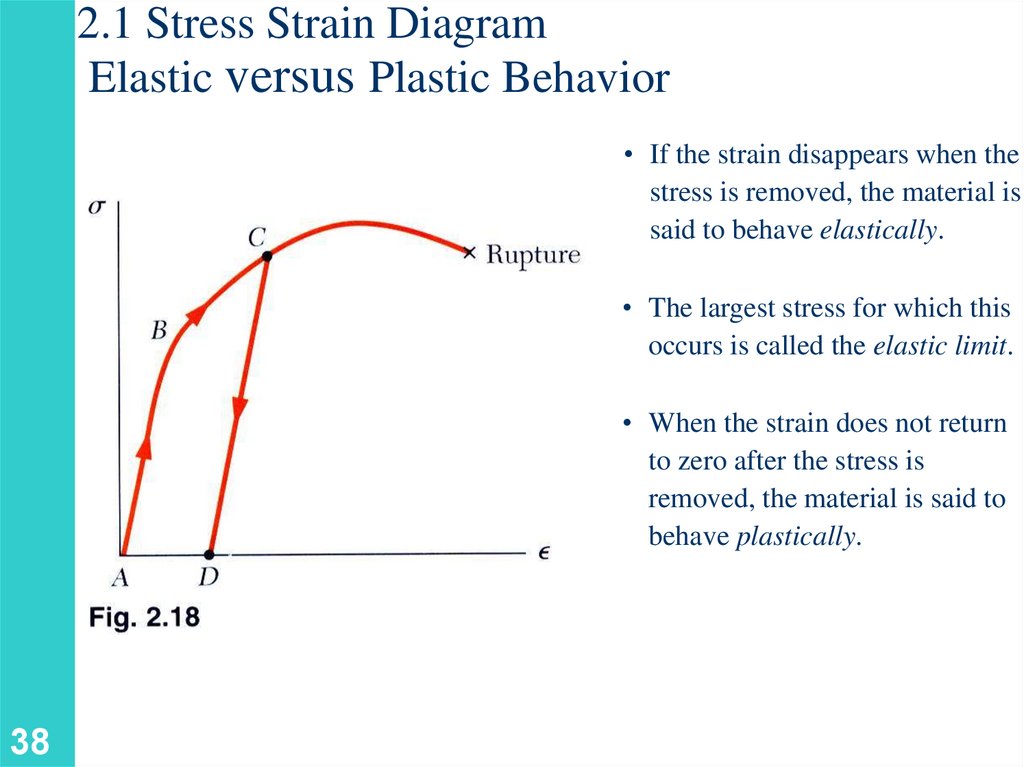
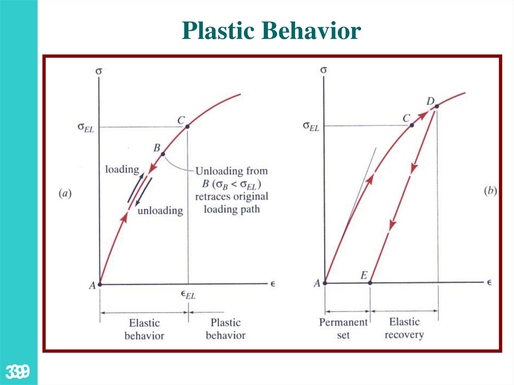
2.1 Stress Strain DiagramElastic versus Plastic Behavior
• If the strain disappears when the
stress is removed, the material is
said to behave elastically.
• The largest stress for which this
occurs is called the elastic limit.
• When the strain does not return
to zero after the stress is
removed, the material is said to
behave plastically.
38
39.
Plastic Behavior39
39
40.
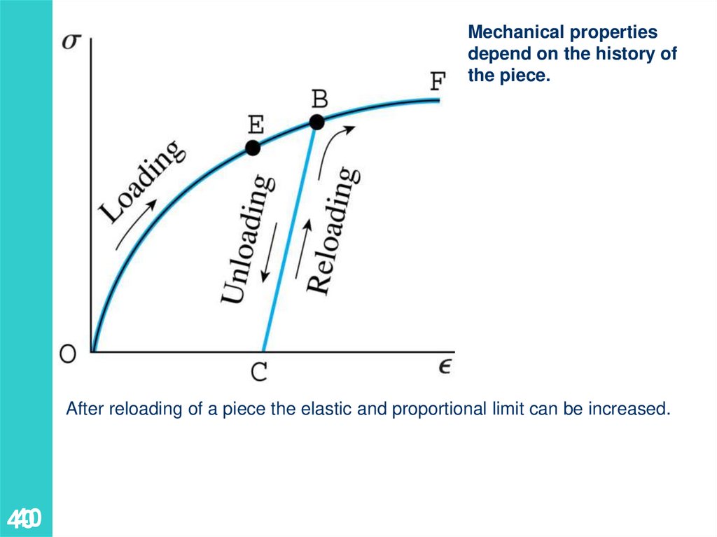
Mechanical propertiesdepend on the history of
the piece.
After reloading of a piece the elastic and proportional limit can be increased.
40
40
41.
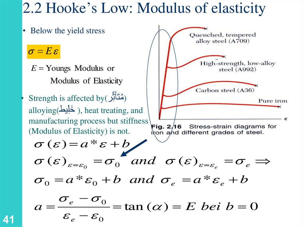
2.2 Hooke’s Low: Modulus of elasticity• Below the yield stress
Ee
E Youngs Modulus or
Modulus of Elasticity
• Strength is affected by() ُمتَأَثِّر
َ ), heat treating, and
alloying(خ ِّليط
manufacturing process but stiffness
(Modulus of Elasticity) is not.
(e ) a * e b
(e )e e 0 and (e )e e e
0
41
e
0 a * e 0 b and e a * e e b
e 0
a
tan ( ) E bei b 0
ee e0
42.
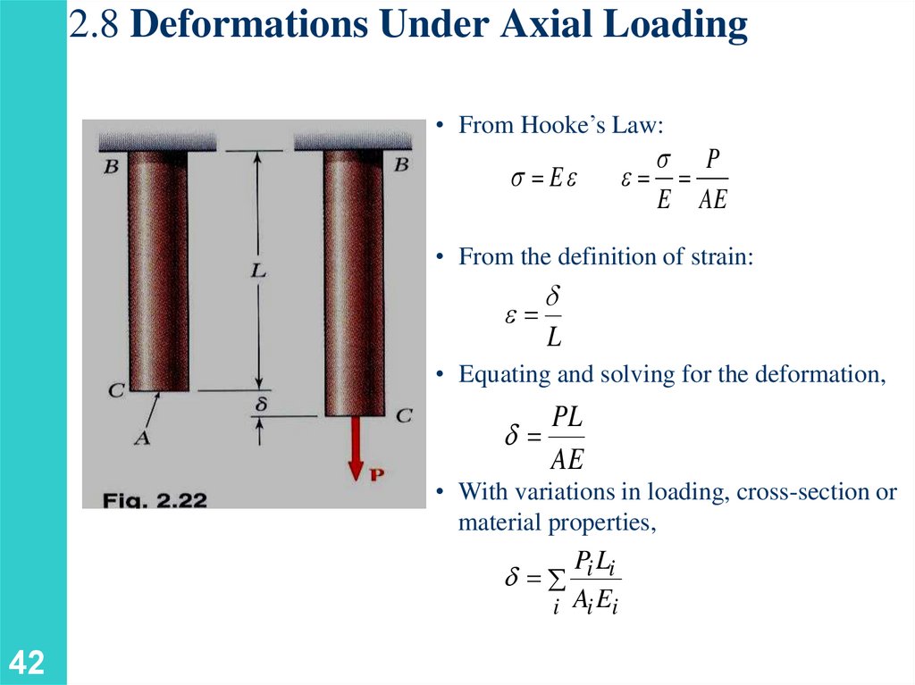
2.8 Deformations Under Axial Loading• From Hooke’s Law:
Ee
P
e
E AE
• From the definition of strain:
e
d
L
• Equating and solving for the deformation,
PL
d
AE
• With variations in loading, cross-section or
material properties,
Pi Li
d
i Ai Ei
42
43.
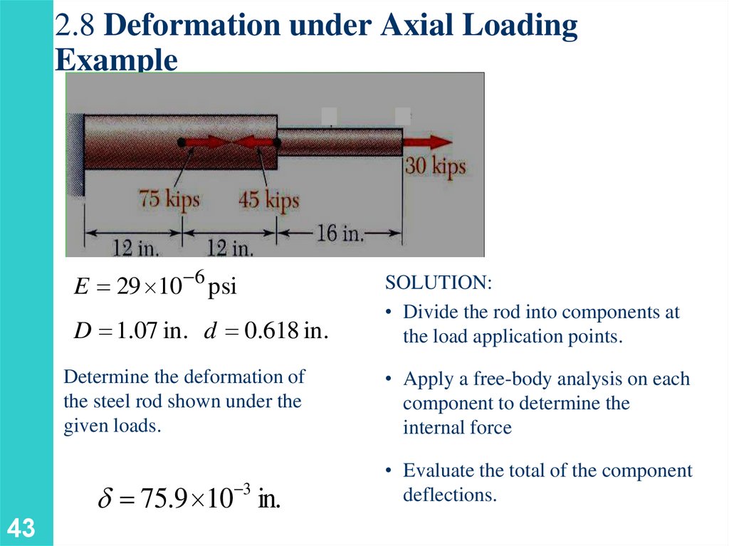
2.8 Deformation under Axial LoadingExample
E 29 10 6 psi
D 1.07 in. d 0.618 in.
Determine the deformation of
the steel rod shown under the
given loads.
• Apply a free-body analysis on each
component to determine the
internal force
d 75.9 10 in.
• Evaluate the total of the component
deflections.
3
43
SOLUTION:
• Divide the rod into components at
the load application points.
44.
2.8 Deformation under Axial LoadingExample
SOLUTION:
• Divide the rod into three
components:
• Apply free-body analysis to each
component to determine internal forces,
P1 60 103 lb
P2 15 103 lb
P3 30 103 lb
• Evaluate total deflection,
Pi Li 1 P1L1 P2 L2 P3 L3
E A1
A2
A3
i Ai Ei
d
60 103 12 15 103 12 30 103 16
6
0
.
9
0
.
9
0
.
3
29 10
1
75.9 10 3 in.
44
L1 L2 12 in.
L3 16 in.
A1 A2 0.9 in 2
A3 0.3 in 2
d 75.9 10 3 in.
45.
4545
46.
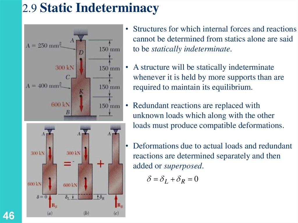
2.9 Static Indeterminacy• Structures for which internal forces and reactions
cannot be determined from statics alone are said
to be statically indeterminate.
• A structure will be statically indeterminate
whenever it is held by more supports than are
required to maintain its equilibrium.
• Redundant reactions are replaced with
unknown loads which along with the other
loads must produce compatible deformations.
• Deformations due to actual loads and redundant
reactions are determined separately and then
added or superposed.
d dL dR 0
46
47.
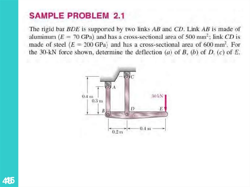
2.9 Static IndeterminacySOLUTION:
• Solve for the displacement at B due to the applied
loads with the redundant constraint released,
P1 0 P2 P3 600 103 N
A1 A2 400 10 6 m 2
P4 900 103 N
A3 A4 250 10 6 m 2
L1 L2 L3 L4 0.150 m
Pi Li 1.125 109
dL
A
E
E
i i i
• Solve for the displacement at B due to the redundant
constraint,
P1 P2 RB
A1 400 10 6 m 2
L1 L2 0.300 m
47
A2 250 10 6 m 2
Pi Li
1.95 103 RB
δR
E
i Ai Ei
48.
2.9 Static Indeterminacy• Require that the displacements due to the loads and due to
the redundant reaction be compatible,
• Find the reaction at A due to the loads and the reaction at B
R A 323kN
RB 577 kN
48
49.
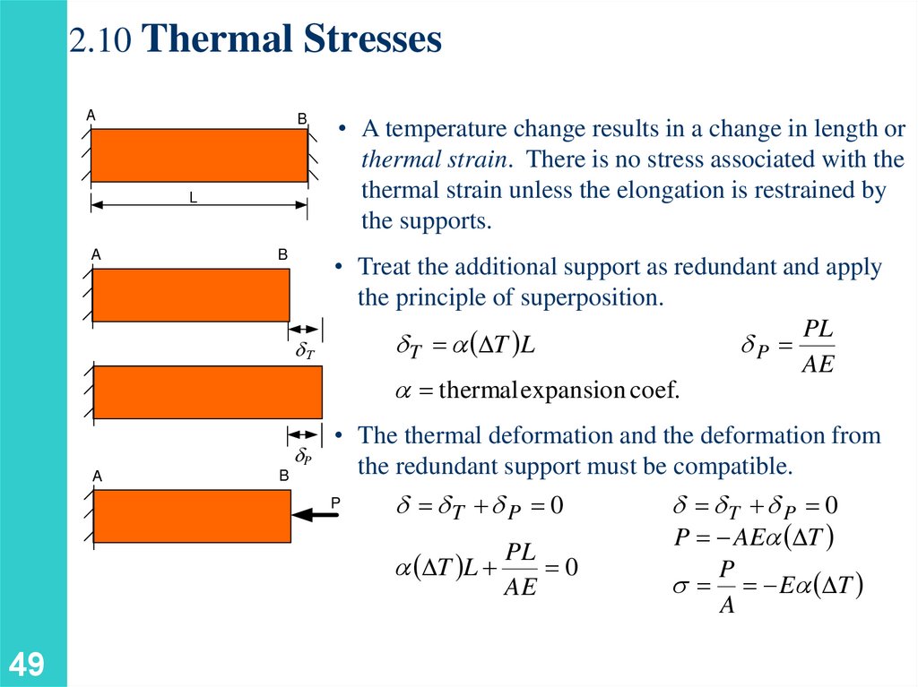
2.10 Thermal StressesA
B
L
A
B
dT
dP
A
B
• A temperature change results in a change in length or
thermal strain. There is no stress associated with the
thermal strain unless the elongation is restrained by
the supports.
• Treat the additional support as redundant and apply
the principle of superposition.
PL
d T T L
dP
AE
thermal expansion coef.
• The thermal deformation and the deformation from
the redundant support must be compatible.
P
d dT d P 0
T L
49
PL
0
AE
d dT d P 0
P AE T
P
E T
A
50.
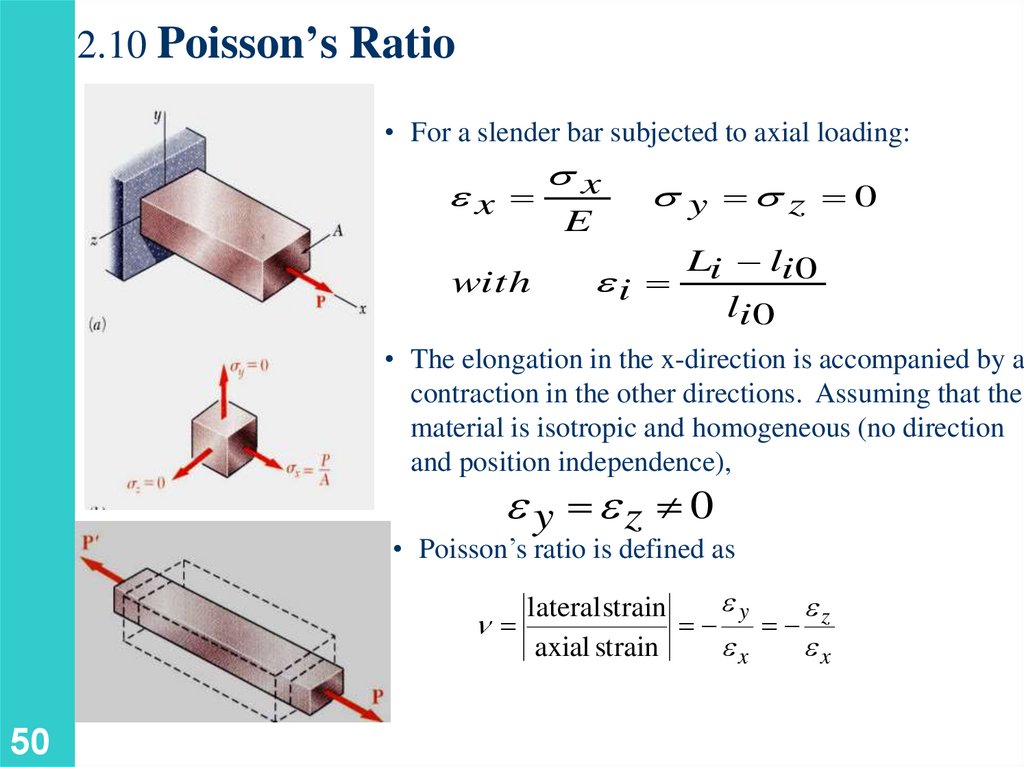
2.10 Poisson’s Ratio• For a slender bar subjected to axial loading:
ex
with
x
E
y z 0
Li li 0
ei
li 0
• The elongation in the x-direction is accompanied by a
contraction in the other directions. Assuming that the
material is isotropic and homogeneous (no direction
and position independence),
e y ez 0
• Poisson’s ratio is defined as
ey
e
lateral strain
n
z
axial strain
ex
ex
50
51.
2.10 Poisson’s RatioSiméon Poisson
“Life is good for only two
things, discovering
mathematics and teaching
mathematics.”
etransverse n e longitudinal
n (Greek letter nu) is called
51
the Poisson’s ratio. Typical values are
in the 0.2 – 0.35 range.
52.
5252
53.
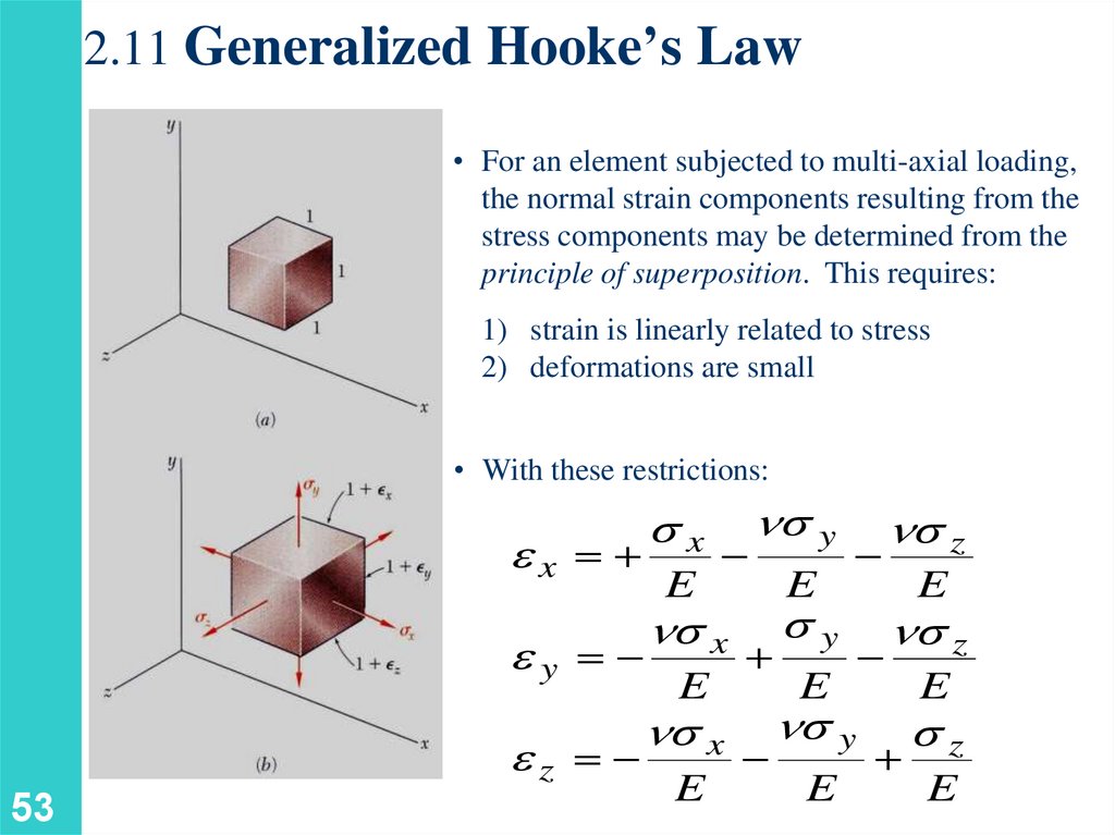
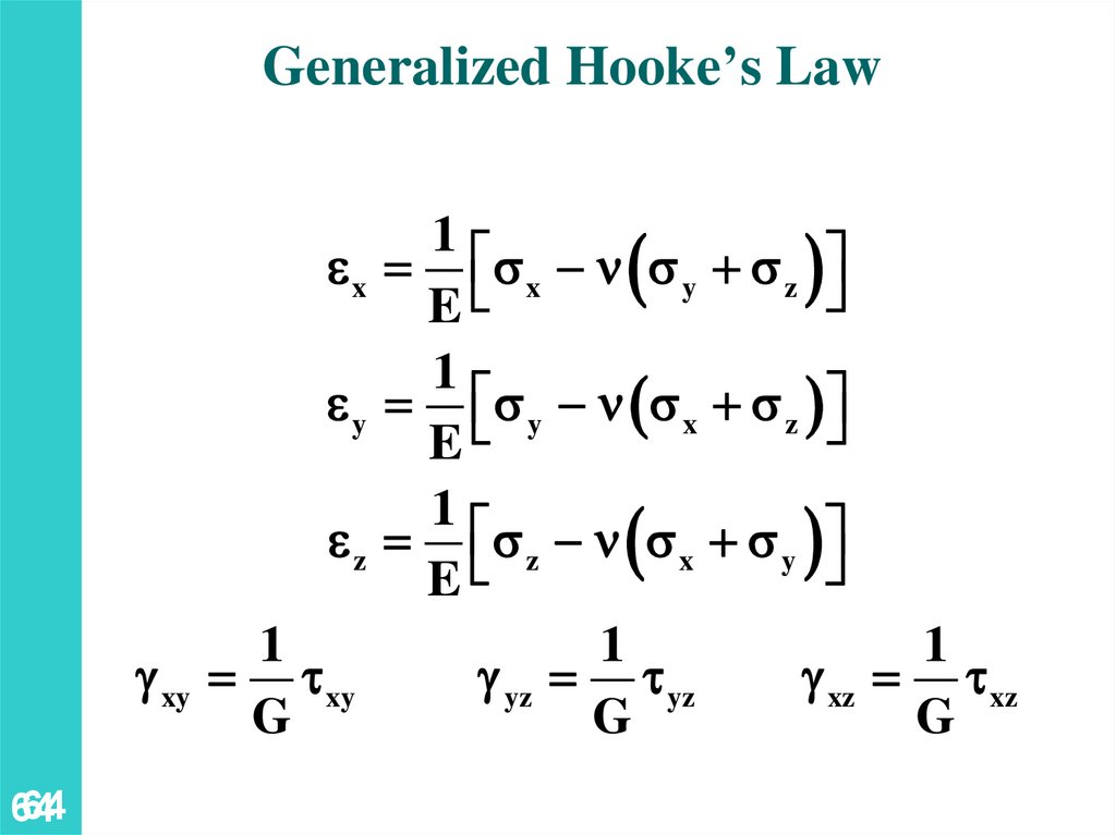
2.11 Generalized Hooke’s Law• For an element subjected to multi-axial loading,
the normal strain components resulting from the
stress components may be determined from the
principle of superposition. This requires:
1) strain is linearly related to stress
2) deformations are small
• With these restrictions:
x
ex
E
ey
53
ez
n x
E
n x
E
n y
E
n z
n z
y
E
n y
E
E
E
z
E
54.
5454
55.
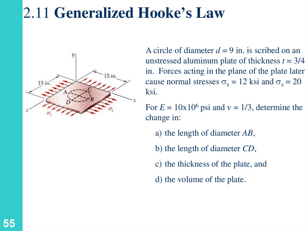
2.11 Generalized Hooke’s LawA circle of diameter d = 9 in. is scribed on an
unstressed aluminum plate of thickness t = 3/4
in. Forces acting in the plane of the plate later
cause normal stresses x = 12 ksi and z = 20
ksi.
For E = 10x106 psi and n = 1/3, determine the
change in:
a) the length of diameter AB,
b) the length of diameter CD,
c) the thickness of the plate, and
d) the volume of the plate.
55
56.
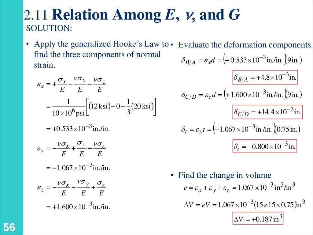
2.11 Relation Among E, n, and GSOLUTION:
• Apply the generalized Hooke’s Law to • Evaluate the deformation components.
find the three components of normal
d B A e x d 0.533 10 3 in./in. 9 in.
strain.
ex
x n y n z
E
E
E
1
12
ksi
0
20
ksi
3
10 106 psi
1
0.533 10 3 in./in.
ey
n x y n z
E
E
E
1.067 10 3 in./in.
ez
n x n y
E
z
E
E
1.600 10 3 in./in.
56
dC
D
dB
A
4.8 10 3 in.
e z d 1.600 10 3 in./in. 9 in.
dC
D
14.4 10 3 in.
d t e y t 1.067 10 3 in./in. 0.75 in.
d t 0.800 10 3 in.
• Find the change in volume
e e x e y e z 1.067 10 3 in 3/in 3
V eV 1.067 10 3 15 15 0.75 in 3
V 0.187 in 3
57.
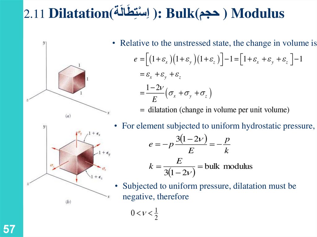
َ ِست2.11 Dilatation(طالَة
ْ ِ) ا: Bulk( ) حجمModulus
• Relative to the unstressed state, the change in volume is
e 1 e x 1 e y 1 e z 1 1 e x e y e z 1
ex e y ez
1 2n
x y z
E
dilatation (change in volume per unit volume)
• For element subjected to uniform hydrostatic pressure,
3 1 2n
p
e p
k
E
k
E
bulk modulus
3 1 2n
• Subjected to uniform pressure, dilatation must be
negative, therefore
0 n 12
57
58.
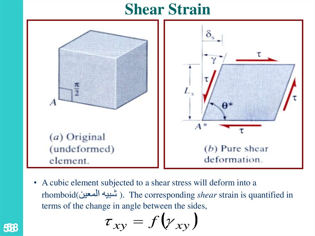
Shear Strain• A cubic element subjected to a shear stress will deform into a
rhomboid() شبيه المعين. The corresponding shear strain is quantified in
terms of the change in angle between the sides,
58
58
xy f g xy
59.
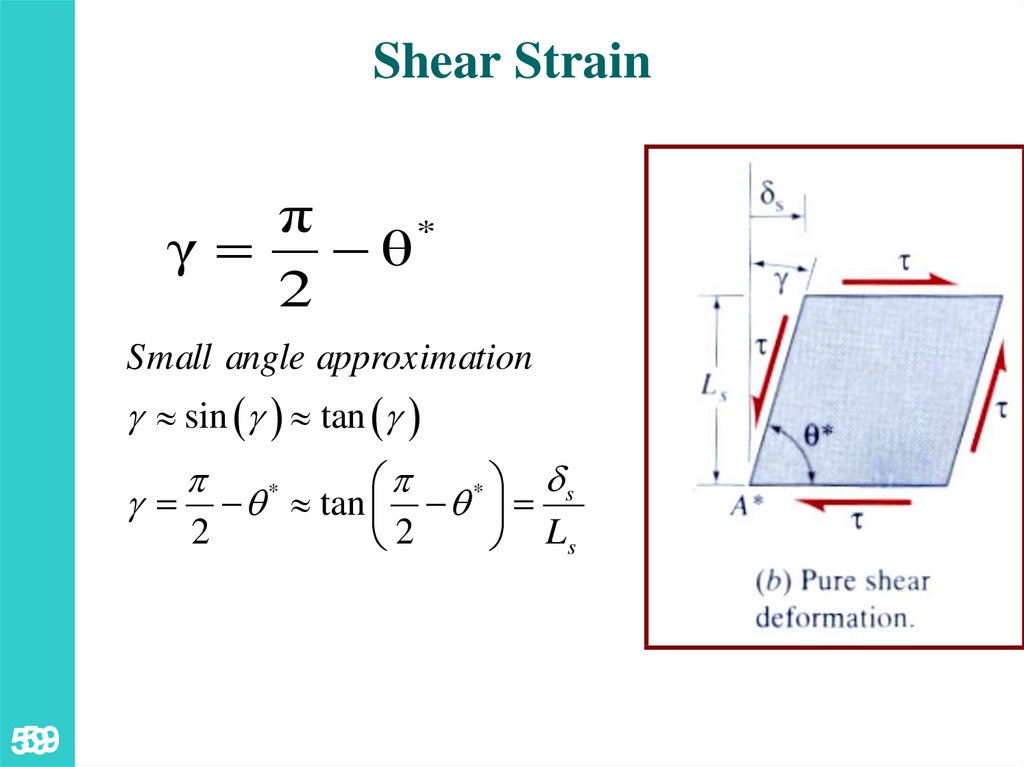
Shear Strainπ
*
γ θ
2
Small angle approximation
g sin g tan g
ds
p
*
g q tan q
2
2
Ls
p
59
59
*
60.
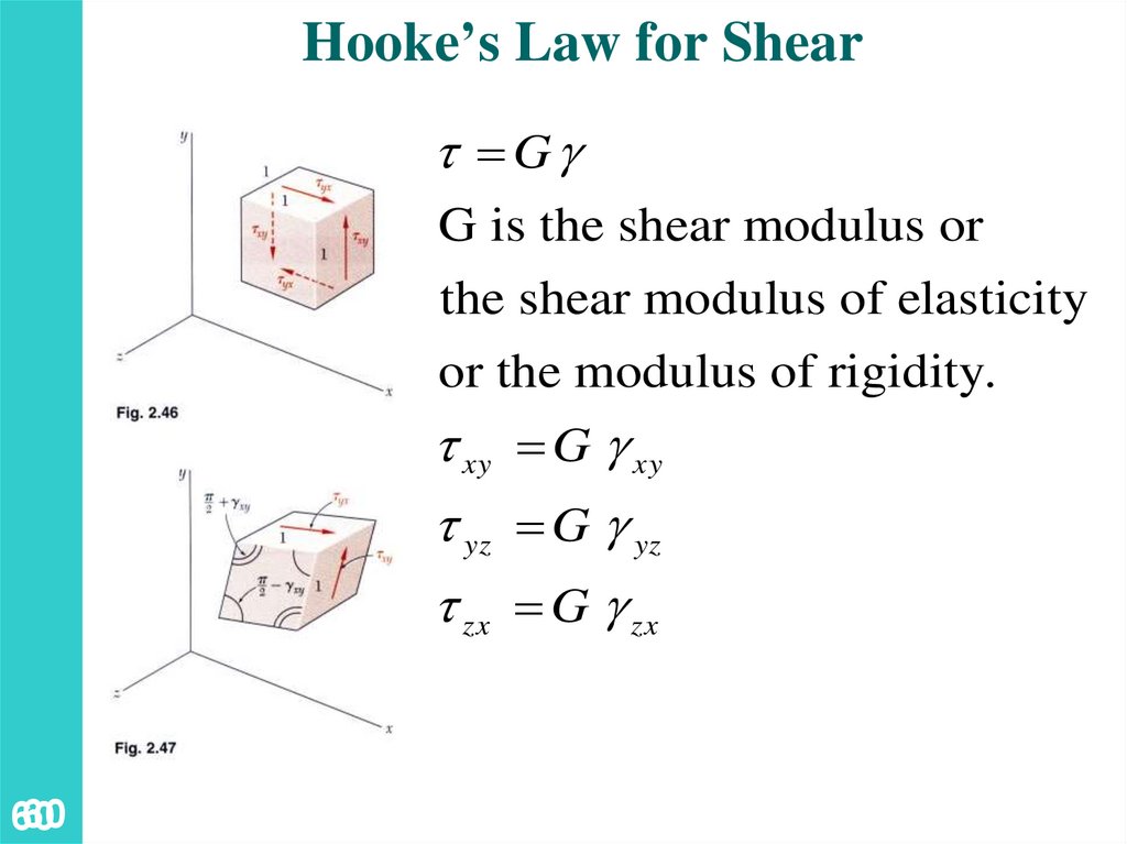
Hooke’s Law for ShearGg
G is the shear modulus or
the shear modulus of elasticity
or the modulus of rigidity.
xy G g xy
yz G g yz
zx G g zx
60
60
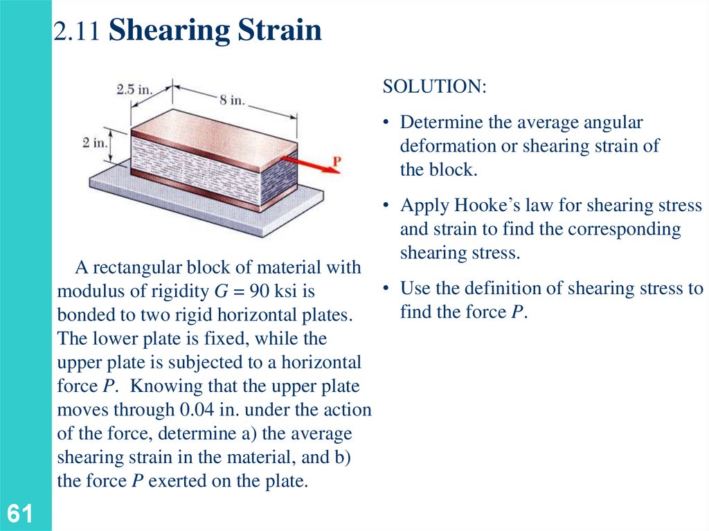
61.
2.11 Shearing StrainSOLUTION:
• Determine the average angular
deformation or shearing strain of
the block.
• Apply Hooke’s law for shearing stress
and strain to find the corresponding
shearing stress.
A rectangular block of material with
• Use the definition of shearing stress to
modulus of rigidity G = 90 ksi is
find the force P.
bonded to two rigid horizontal plates.
The lower plate is fixed, while the
upper plate is subjected to a horizontal
force P. Knowing that the upper plate
moves through 0.04 in. under the action
of the force, determine a) the average
shearing strain in the material, and b)
the force P exerted on the plate.
61
62.
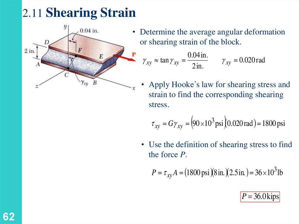
2.11 Shearing Strain• Determine the average angular deformation
or shearing strain of the block.
g xy tan g xy
0.04 in.
2 in.
g xy 0.020 rad
• Apply Hooke’s law for shearing stress and
strain to find the corresponding shearing
stress.
xy Gg xy 90 103 psi 0.020 rad 1800 psi
• Use the definition of shearing stress to find
the force P.
P xy A 1800 psi 8 in. 2.5 in. 36 103 lb
P 36.0 kips
62
63.
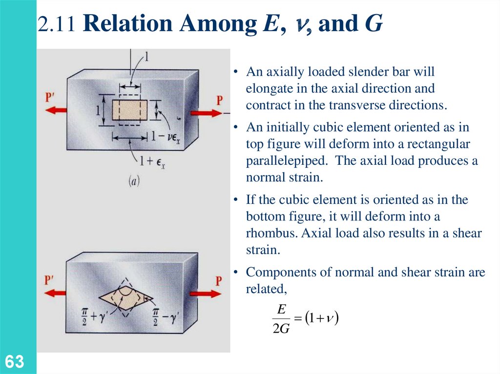
2.11 Relation Among E, n, and G• An axially loaded slender bar will
elongate in the axial direction and
contract in the transverse directions.
• An initially cubic element oriented as in
top figure will deform into a rectangular
parallelepiped. The axial load produces a
normal strain.
• If the cubic element is oriented as in the
bottom figure, it will deform into a
rhombus. Axial load also results in a shear
strain.
• Components of normal and shear strain are
related,
E
1 n
2G
63
64.
Generalized Hooke’s Lawg xy
64
64
1
e x x n y z
E
1
e y y n x z
E
1
e z z n x y
E
1
1
1
xy
g yz yz
g xz xz
G
G
G
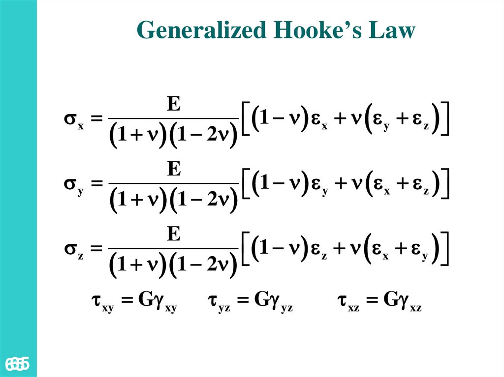
65.
Generalized Hooke’s LawE
1 n e x n e y e z
x
1 n 1 2n
E
1 n e y n e x e z
y
1 n 1 2n
E
1 n e z n e x e y
z
1 n 1 2n
xy Gg xy
65
65
yz Gg yz
xz Gg xz
66.
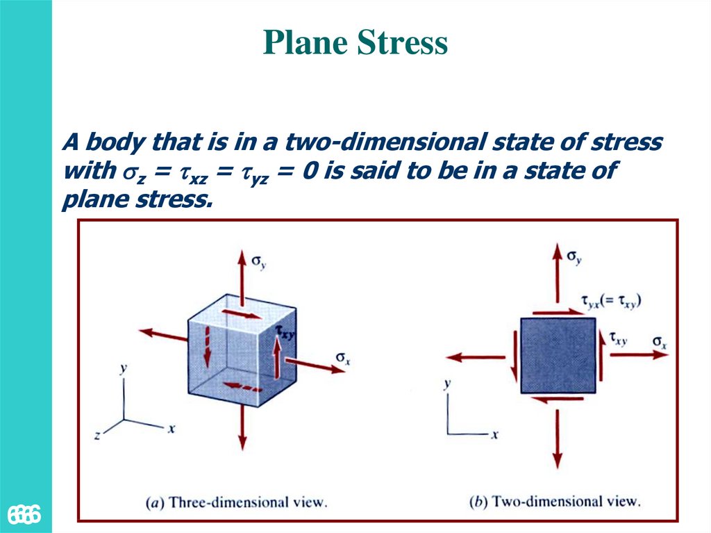
Plane StressA body that is in a two-dimensional state of stress
with z = xz = yz = 0 is said to be in a state of
plane stress.
66
66
67.
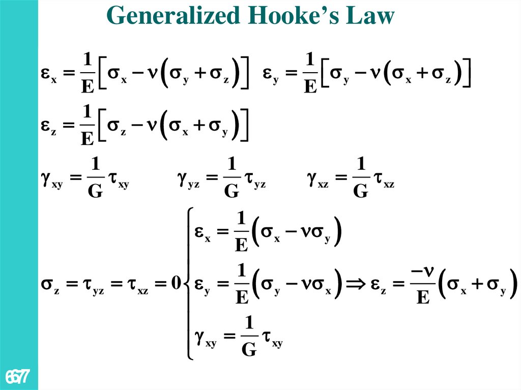
Generalized Hooke’s Law1
1
e x x n y z e y y n x z
E
E
1
e z z n x y
E
1
1
1
g xy xy
g yz yz
g xz xz
G
G
G
1
e x E x n y
1
n
z yz xz 0 e y
y n x e z
x y
E
E
1
g xy G xy
67
67
68.
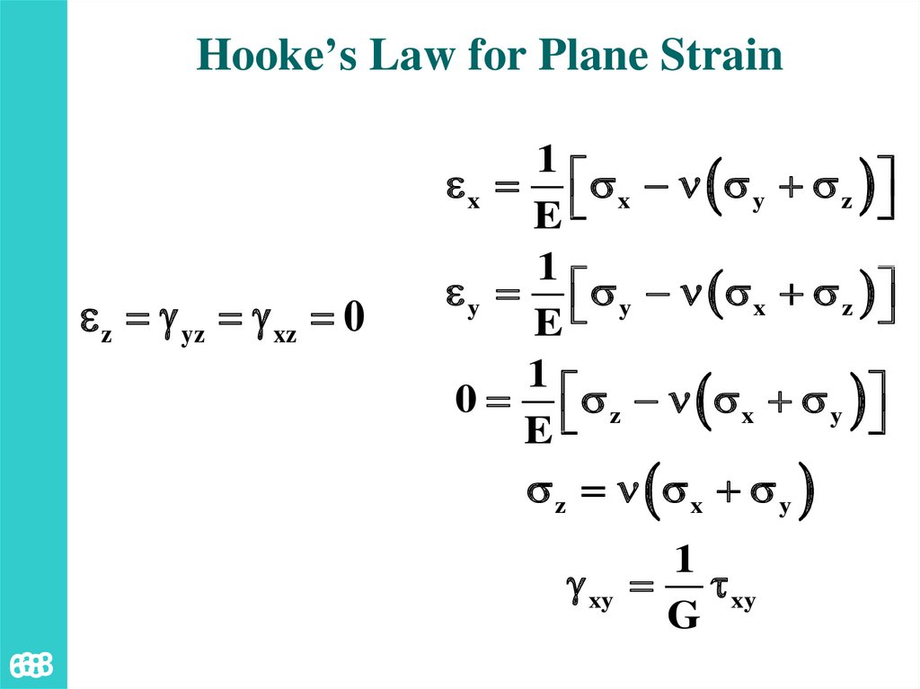
Hooke’s Law for Plane Straine z g yz g xz 0
1
e x x n y z
E
1
e y y n x z
E
1
0 z n x y
E
z n x y
g xy
68
68
1
xy
G
69.
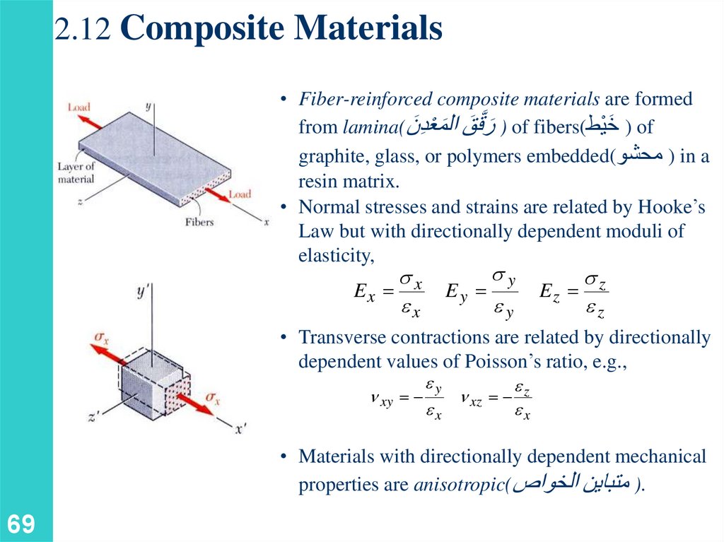
2.12 Composite Materials• Fiber-reinforced composite materials are formed
َ ) of
from lamina( َ ) َر َّققَ ال َمعْدِّنof fibers(خيْط
graphite, glass, or polymers embedded( ) محشوin a
resin matrix.
• Normal stresses and strains are related by Hooke’s
Law but with directionally dependent moduli of
elasticity,
y
x
Ex
Ey
Ez z
ex
ey
ez
• Transverse contractions are related by directionally
dependent values of Poisson’s ratio, e.g.,
n xy
ey
e
n xz z
ex
ex
• Materials with directionally dependent mechanical
properties are anisotropic() متباين الخواص.
69
70.
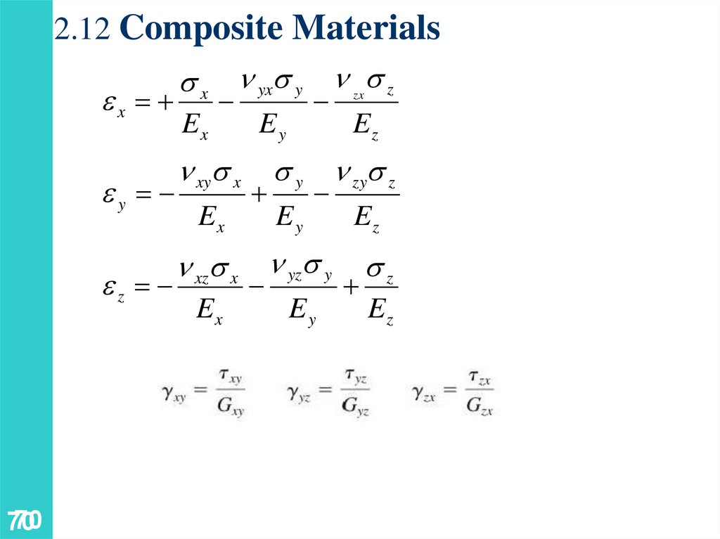
2.12 Composite Materialsx n yx y n z
ex
zx
Ex
ey
ez
70
70
n xy x
Ex
Ey
Ez
y n zy z
Ey
n xz x n yz y
Ex
Ey
Ez
z
Ez
71.
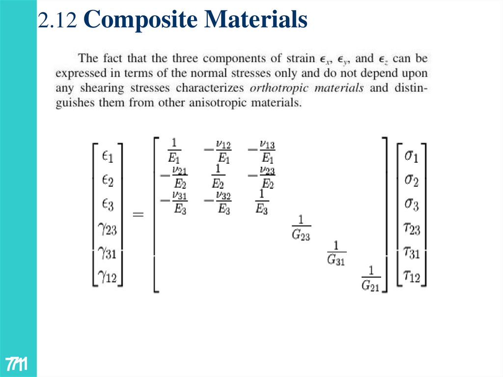
2.12 Composite Materials71
71
72.
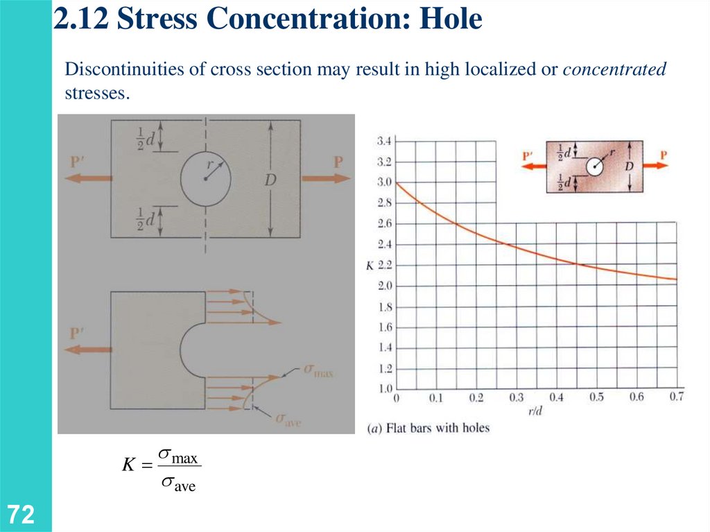
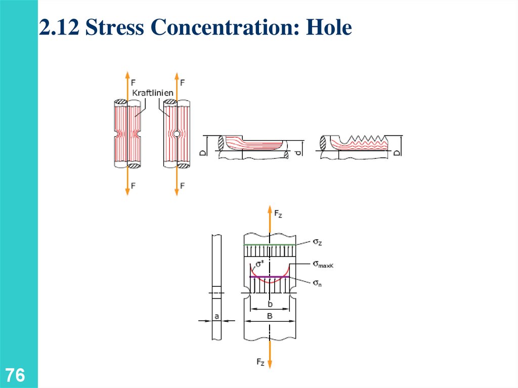
2.12 Stress Concentration: HoleDiscontinuities of cross section may result in high localized or concentrated
stresses.
max
K
ave
72
73.
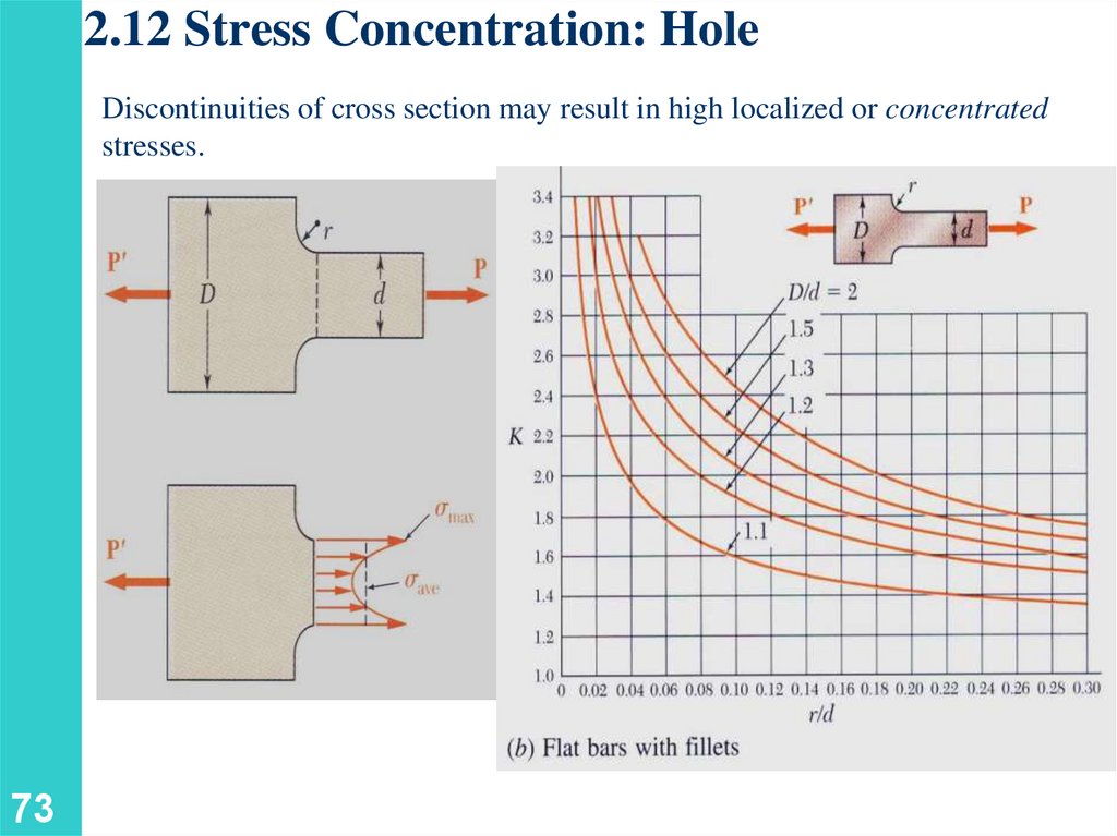
2.12 Stress Concentration: HoleDiscontinuities of cross section may result in high localized or concentrated
stresses.
73
74.
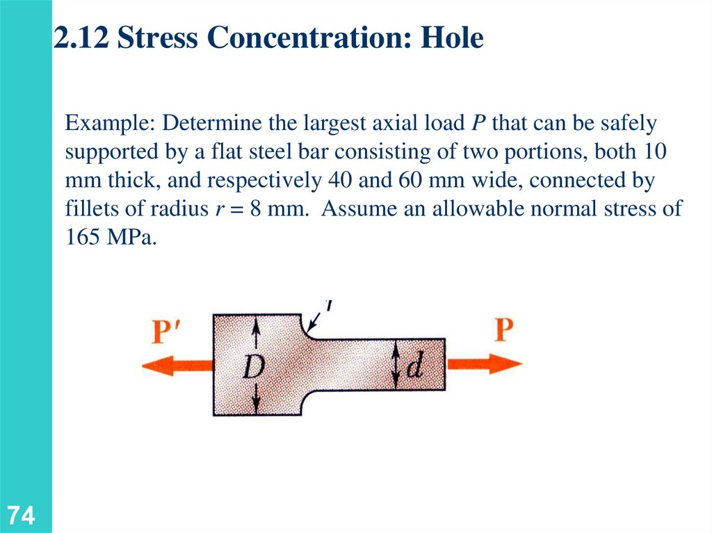
2.12 Stress Concentration: HoleExample: Determine the largest axial load P that can be safely
supported by a flat steel bar consisting of two portions, both 10
mm thick, and respectively 40 and 60 mm wide, connected by
fillets of radius r = 8 mm. Assume an allowable normal stress of
165 MPa.
74
75.
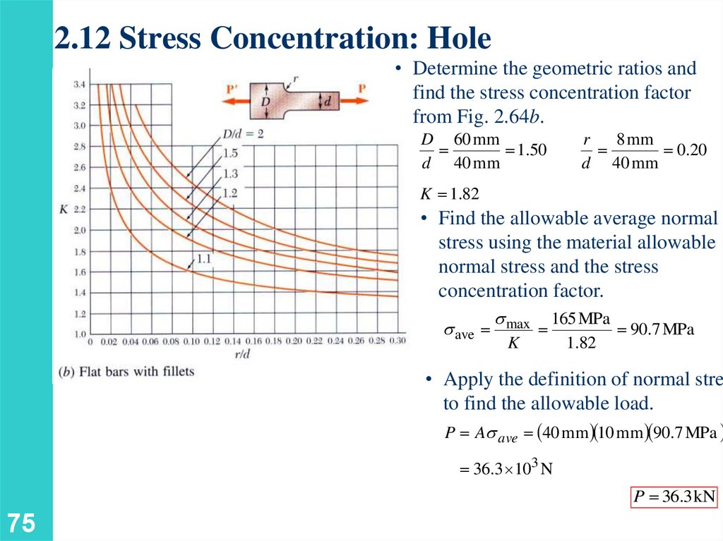
2.12 Stress Concentration: Hole• Determine the geometric ratios and
find the stress concentration factor
from Fig. 2.64b.
D 60 mm
1.50
d 40 mm
r
8 mm
0.20
d 40 mm
K 1.82
• Find the allowable average normal
stress using the material allowable
normal stress and the stress
concentration factor.
ave
max
K
165 MPa
90.7 MPa
1.82
• Apply the definition of normal stres
to find the allowable load.
P A ave 40 mm 10 mm 90.7 MPa
36.3 103 N
P 36.3 kN
75
76.
2.12 Stress Concentration: Hole76