


 Менеджмент
Похожие презентации:


Workplace Organization. Lean OS Development & Global BOP Team
1.
Workplace OrganizationLean OS Development & Global BOP Team
DPGP-4.3-ME-03 A01 Effective date: 02/18/2013
1
Lean OS Develop. Team / Global BOP Team
2.
1. Workplace Organization PurposeTo provide an ergonomic and safe work environment
for operators, standardized processes that comply with
quality requirements, producing right part, right time,
right quantity, while achieving high manpower/capacity
utilization.
DPGP-4.3-ME-03 A01 Effective date: 02/18/2013
2
Lean OS Develop. Team / Global BOP Team
3.
3. Handling & ProtectionHow to Accommodate Components at the Point of Use
In order to develop a good parts presentation for the operators
follow the Delivery Routes Guideline. Key points are the
following:
Select Right Container
(Size & Type)
• D. Routes have to be performed based on fixed time & 1 hour frequency,
due to that at the point of use is necessary to have 2 kanban cards (one
behind the other) representing 2 hours by kanban
• Define Right Container to be used at point of use (definition is done by
PC&L based on the dimensions of the components and the line targets
submitted by ME and afterwards the assigned container sizes are confirmed
together by ME and PC&L):
•Define 3 container type that can contain 2 hours consumption per
part ( 1 liter / 2,5 liters / 5 liters)
•a Cup for very small parts – (seals, secondary lock,…), cup is just
to measure the quantity to be loaded to the small container
• If supplier pack represents less than 8 hours consumption should be
delivery in the original pack to the point of use (ME / PCL should analyze if it
is feasible)
Easy for pickup
Kanban should be visible all
time
Full fill the containers in the
right way – parts should not
follow down anytime
• If necessary to repack it should be selected the smallest container that
contains 2 hours consumption.
• Quality should define what are the parts that cannot be repacked and this
information should exist in PFMEA.
Separators in between the
containers to avoid the
wrong size container.
• All parts have to be identified all the time and visible from the operator’s
point of view.
Loading
•Material should be available at the exact point of use, rack should provide
conditions to avoid mixed parts and to assure the FIFO. Cells should be
prepared in order to be loaded by the exterior not to disturb operators.
Special shuttles to reorder the parts have to be installed (see in cell design
chapter)
DPGP-4.3-ME-03 A01 Effective date: 02/18/2013
3
Picking
Shuttle + KB collect Box
Lean OS Develop. Team / Global BOP Team
4.
3. Handling & ProtectionSummary Matrix
3.2 Wires:
700mm
Length: 700mm<α<1300mm
1300mm
DPGP-4.3-ME-03 A01 Effective date: 02/18/2013
4
Lean OS Develop. Team / Global BOP Team
5.
3. Handling & ProtectionHow to Accommodate Wires at the Cutting Supermarket
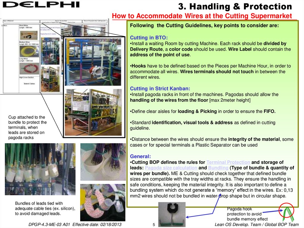
Following the Cutting Guidelines, key points to consider are:
Cutting in BTO:
•Install a waiting Room by cutting Machine. Each rack should be divided by
Delivery Route, a color code should be used. Wire Label should contain the
address of the point of use.
•Hooks have to be defined based on the Pieces per Machine Hour, in order to
accommodate all wires. Wires terminals should not touch in between the
different wires.
Cutting in Strict Kanban:
•Install pagoda racks in front of the machines. Pagodas should allow the
handling of the wires from the floor [max 2meter height]
•Define clear aisles for loading & Picking in order to ensure the FIFO.
Cup attached to the
bundle to protect the
terminals, when
leads are stored on
pagoda racks
•Standard identification, visual tools & address as defined in cutting
guideline.
•Distance between the wires should ensure the integrity of the material, some
cases or for special terminals a Plastic Separator can be used
General:
•Cutting BOP defines the rules for Terminal Protection and storage of
leads: Pagoda size calculation and Bundling (Type of bundle & quantity of
wires per bundle). ME & Cutting should check together that defined bundle
sizes are compatible with the tray widths at racks. They ensure the handling in
safe conditions, keeping the material integrity. It is also important to define a
bundling system which do not generate a “memory” effect in the wires. Ex: 0,13
mm2 wires should not be bundled in water-drop shape but in circular shape.
Bundles of leads tied with
adequate cable ties (ex. silicon),
to avoid damaged leads.
DPGP-4.3-ME-03 A01 Effective date: 02/18/2013
5
Pagoda hook
protection to avoid
bundle memory effect
Lean OS Develop. Team / Global BOP Team
6.
3. Handling & ProtectionHow to Accommodate Wires at the Point of Use
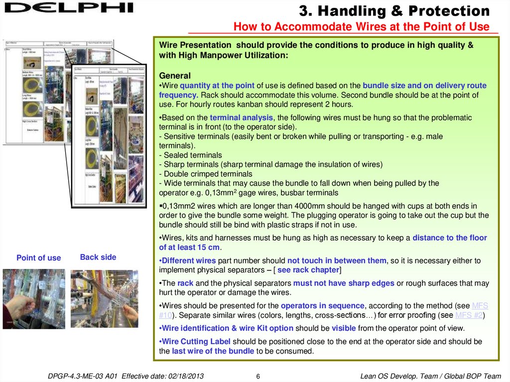
Wire Presentation should provide the conditions to produce in high quality &
with High Manpower Utilization:
General
•Wire quantity at the point of use is defined based on the bundle size and on delivery route
frequency. Rack should accommodate this volume. Second bundle should be at the point of
use. For hourly routes kanban should represent 2 hours.
•Based on the terminal analysis, the following wires must be hung so that the problematic
terminal is in front (to the operator side).
- Sensitive terminals (easily bent or broken while pulling or transporting - e.g. male
terminals).
- Sealed terminals
- Sharp terminals (sharp terminal damage the insulation of wires)
- Double crimped terminals
- Wide terminals that may cause the bundle to fall down when being pulled by the
operator e.g. 0,13mm2 gage wires, busbar terminals
0,13mm2 wires which are longer than 4000mm should be hanged with cups at both ends in
order to give the bundle some weight. The plugging operator is going to take out the cup but the
bundle should still be bind with plastic straps if not in use.
•Wires, kits and harnesses must be hung as high as necessary to keep a distance to the floor
of at least 15 cm.
Point of use
Back side
•Different wires part number should not touch in between them, so it is necessary either to
implement physical separators – [ see rack chapter]
•The rack and the physical separators must not have sharp edges or rough surfaces that may
hurt the operator or damage the wires.
•Wires should be presented for the operators in sequence, according to the method (see MFS
#10). Separate similar wires (colors, lengths, cross-sections…) for error proofing (see MFS #2)
•Wire identification & wire Kit option should be visible from the operator point of view.
•Wire Cutting Label should be positioned close to the end at the operator side and should be
the last wire of the bundle to be consumed.
DPGP-4.3-ME-03 A01 Effective date: 02/18/2013
6
Lean OS Develop. Team / Global BOP Team
7.
3. Handling & ProtectionHow to Accommodate Wires at the Point of Use
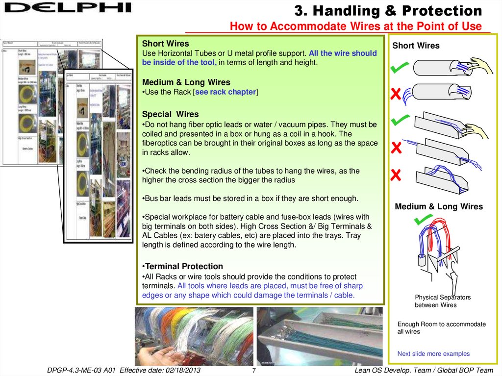
Short Wires
Use Horizontal Tubes or U metal profile support. All the wire should
be inside of the tool, in terms of length and height.
Short Wires
Medium & Long Wires
•Use the Rack [see rack chapter]
Special Wires
•Do not hang fiber optic leads or water / vacuum pipes. They must be
coiled and presented in a box or hung as a coil in a hook. The
fiberoptics can be brought in their original boxes as long as the space
in racks allow.
•Check the bending radius of the tubes to hang the wires, as the
higher the cross section the bigger the radius
•Bus bar leads must be stored in a box if they are short enough.
Medium & Long Wires
•Special workplace for battery cable and fuse-box leads (wires with
big terminals on both sides). High Cross Section &/ Big Terminals &
AL Cables (ex: batery cables, etc) are placed into the trays. Tray
length is defined according to the wire length.
•Terminal Protection
•All Racks or wire tools should provide the conditions to protect
terminals. All tools where leads are placed, must be free of sharp
edges or any shape which could damage the terminals / cable.
Physical Separators
between Wires
Enough Room to accommodate
all wires
Next slide more examples
DPGP-4.3-ME-03 A01 Effective date: 02/18/2013
7
Lean OS Develop. Team / Global BOP Team
8.
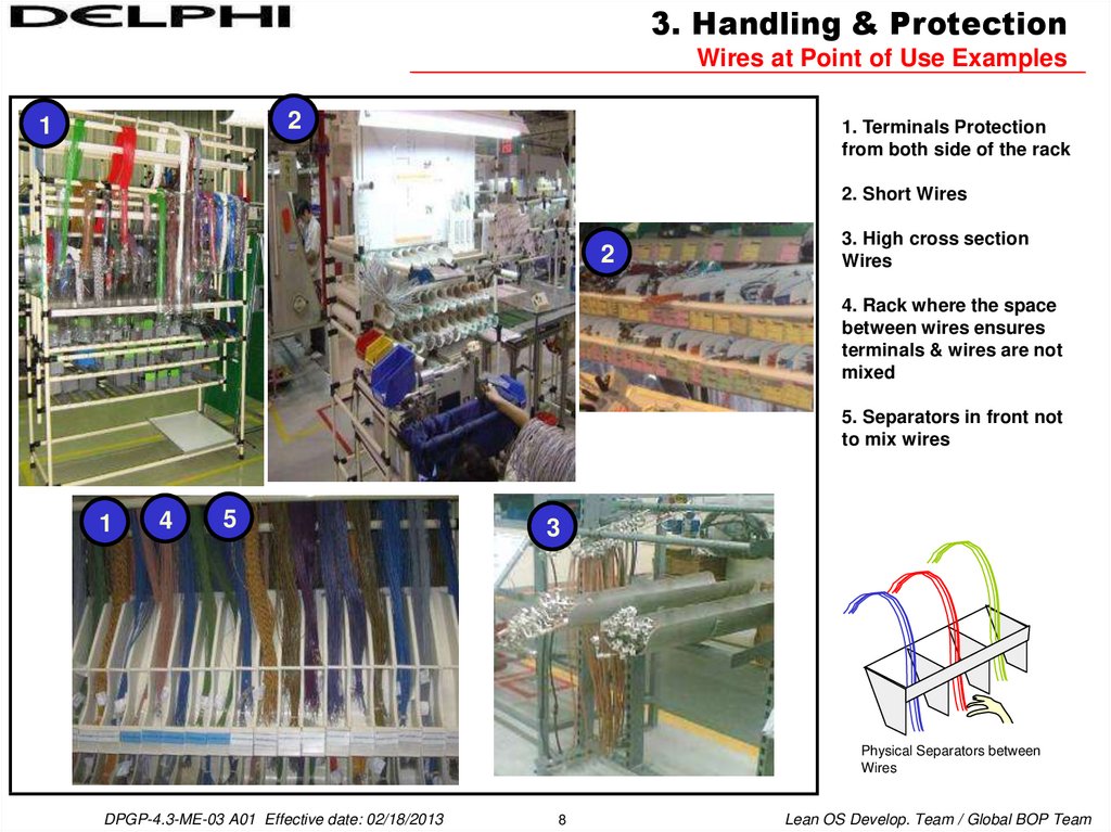
3. Handling & ProtectionWires at Point of Use Examples
2
1
1. Terminals Protection
from both side of the rack
2. Short Wires
2
3. High cross section
Wires
4. Rack where the space
between wires ensures
terminals & wires are not
mixed
5. Separators in front not
to mix wires
1
4
5
3
Physical Separators between
Wires
DPGP-4.3-ME-03 A01 Effective date: 02/18/2013
8
Lean OS Develop. Team / Global BOP Team
9.
3. Handling & ProtectionWires at Point of Use Examples
6. Terminals Protection
from the front side of the
rack
6
7. Terminals Protection
from the back side of the
rack with transparent
flexible tool
All systems with an easy
concept to load & pick up
leads
Different leads codes will
not touch the other ones
placed close on the racks.
7
DPGP-4.3-ME-03 A01 Effective date: 02/18/2013
9
Lean OS Develop. Team / Global BOP Team
10.
3. Handling & ProtectionWires at Point of Use Examples
8
10
8. Terminals Protection
from the back side of the
rack with transparent
flexible tool
9. Terminals Protection
from the front side of the
rack
10. Optical Fibers in
containers
9
11
12
11. Battery Cable in
special trays with 2
positions per wire to
support delivery routes
12. For high cross section
cables with not very big
terminals, waterfall type
special trays
9
DPGP-4.3-ME-03 A01 Effective date: 02/18/2013
10
Lean OS Develop. Team / Global BOP Team
11.
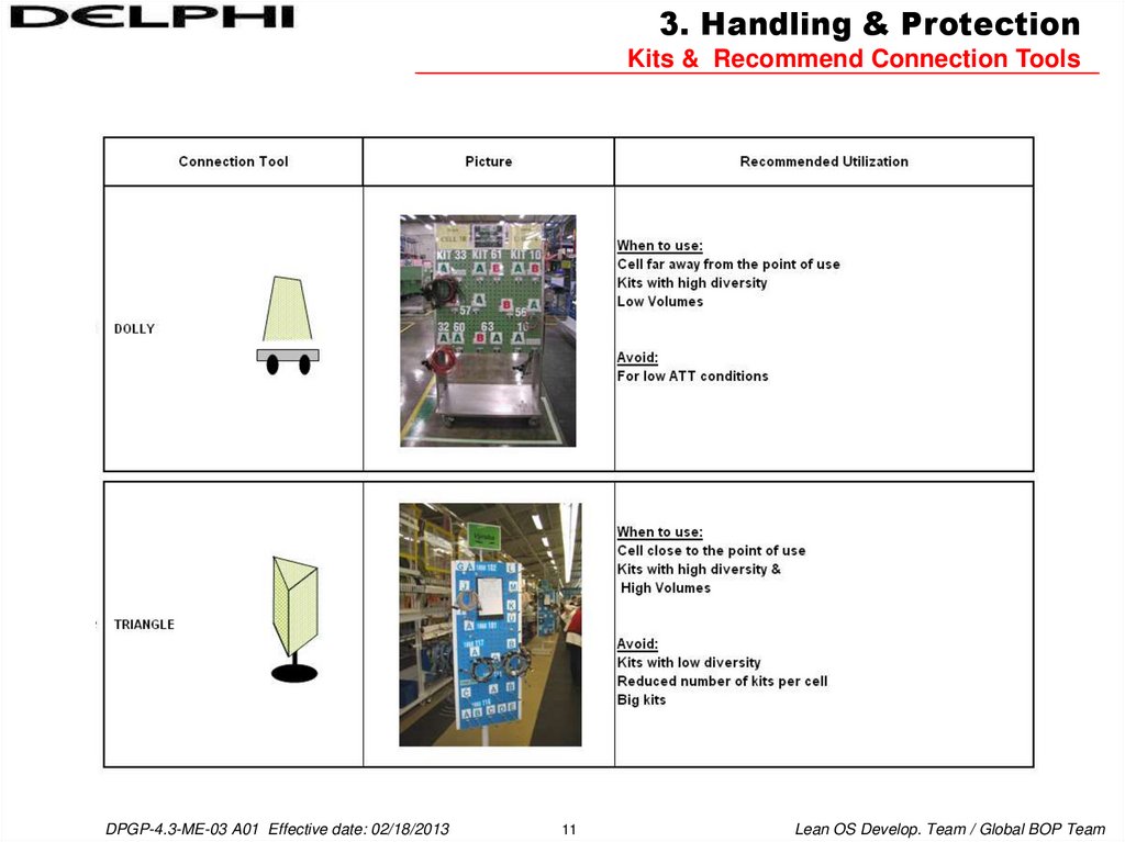
3. Handling & ProtectionKits & Recommend Connection Tools
DPGP-4.3-ME-03 A01 Effective date: 02/18/2013
11
Lean OS Develop. Team / Global BOP Team
12.
3. Handling & ProtectionKits & Recommend Connection Tools
DPGP-4.3-ME-03 A01 Effective date: 02/18/2013
12
Lean OS Develop. Team / Global BOP Team
13.
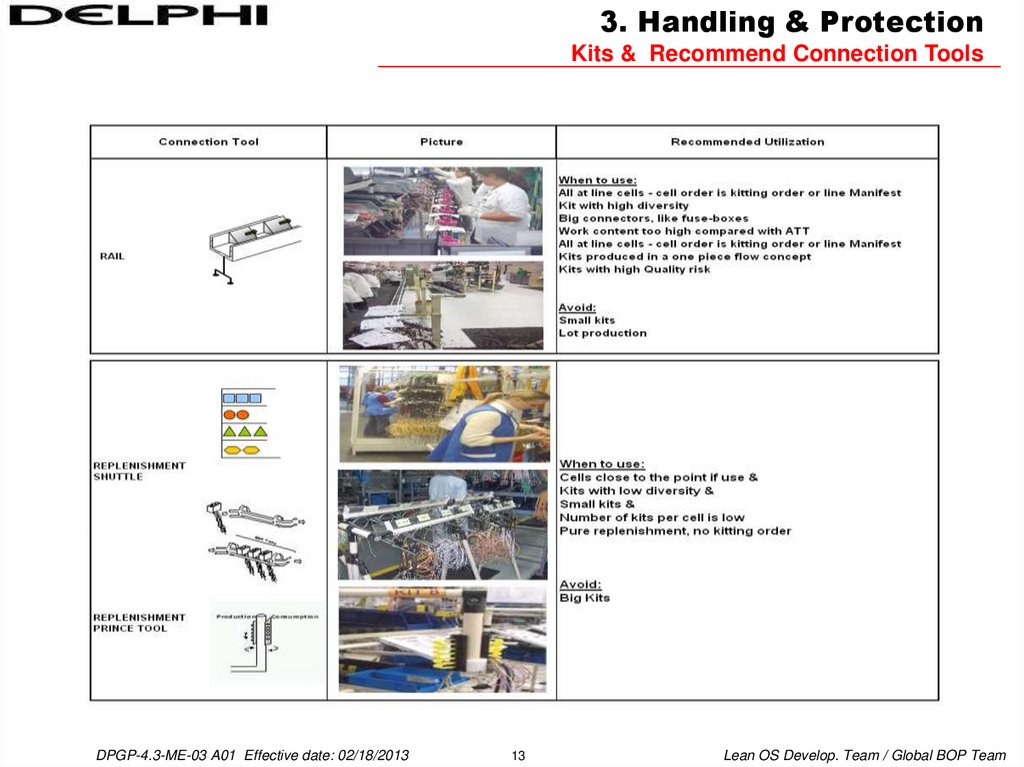
3. Handling & ProtectionKits & Recommend Connection Tools
DPGP-4.3-ME-03 A01 Effective date: 02/18/2013
13
Lean OS Develop. Team / Global BOP Team
14.
Rack Design ConceptSpecificities for Wire Racks
The rack design and dimensions shown in the rack drawings are only
examples, rack design and dimensions can be changed as long as the rack
design criteria is respected.
Example of EU – Wire Rack
Wire Rack Design Criteria:
•Minimum reaching point for all materials/ Splice / kit/ lead coil is 700mm
from the floor. (A)
•Any accessory starts at minimum 150mm above from the floor. (B)
•In the down part there can be 2 layers of tubes for cable protection. (C)
•The minimum distance between any two level of materials (components,
cables) is 150mm. (D)
•There can be 2 levels of long wires. (E)
•The long wire trays, if available, should not be parallel, but there should
be angle difference between them. (F)
•Each rack should have pools at the bottom, where the operators work; in
order to prevent any material to touch the floor. (G)
•There should be belts at the upper side of the cable trays to prevent the
hanged wires come out of the trays. (H)
•Maximum number of wires that can be hanged on a rack depends on the
rack width, tray width, number of levels of wires on that rack, if the wires
are not tangled to each other at the back side of the rack and if the
transporter is able to hang the wires easily from the back side of the rack.
•For all splice / lead / kit coils to be hanged on the rack, each line should
be seperated with seperators.
•The ideal levels on racks should be defined for each region. For Europe
the values are given below:
Ideal Levels on Racks
IDEAL MINIMUM
(mm)
RACK LEVEL MIN (mm) MAX (mm)
COMPONENT
700
1500
800
WIRE
700
1700
800
(H) There should be belts to
prevent the wires coming out
of trays
(E) 2 levels of
long wire trays
(F) Long wire trays
should not be parallel
(D) Min
150mm
between any
two levels of
components
IDEAL MAXIMUM
(mm)
1300
1300
(C) Max 2 layers of tubes at the back of the rack
(G) There should be pools in the front at the bottom
DPGP-4.3-ME-03 A01 Effective date: 02/18/2013
Operator side
14
(B) Min height from
the ground = 150mm
(A) Min reaching point
for materials from the
ground = 700mm
Lean OS Develop. Team / Global BOP Team
15.
Rack Design ConceptExample of Europe - Rack Type 3
FRONT VIEW
BACK VIEW
CUBICAL VIEW
Operator
side
DPGP-4.3-ME-03 A01 Effective date: 02/18/2013
15
Lean OS Develop. Team / Global BOP Team
16.
Cell DesignSome Examples & Distances
The connection tool is chosen according to the connection tool matrix. The working area for operators should be min 0,8m.
an example layout is given below:
Space between racks
Assembly lines
2,6 meters
1m
1,6 m
1,6 meters
0,8 m
DPGP-4.3-ME-03 A01 Effective date: 02/18/2013
16
0,8 m
Lean OS Develop. Team / Global BOP Team
17.
Cell DesignSome Examples & Distances
The connection tool is chosen according to the connection tool matrix. The working area for operators should be min 0,8m.
an example layout is given below:
3,6 meters
0,8m
0,8m
1m
1m
1,6 meters
0,8 m
DPGP-4.3-ME-03 A01 Effective date: 02/18/2013
17
0,8 m
Lean OS Develop. Team / Global BOP Team
18.
Cell DesignSome Examples & Distances
The connection tool is chosen according to the connection tool matrix. The working area for operators should be min 0,8m.
4,4 meters
1m
DPGP-4.3-ME-03 A01 Effective date: 02/18/2013
18
0,8m
0,8m
0,8m
1m
Lean OS Develop. Team / Global BOP Team
19.
Cell Design ConceptExamples of Layouts
Address system has to be clearly visible. Layout
markings to support Visual Management.
Assembly area layout has to support clear
material flow and the Visual Management.
Workplace organization in a “one piece flow” kit cell.
DPGP-4.3-ME-03 A01 Effective date: 02/18/2013
19
Lean OS Develop. Team / Global BOP Team
20.
5. Standardized WorkImpact of the Workplace Organization on the Manpower Results
Good WPO can lead to reduction in Element Time., like in example below.
Before
WCT
CT 98 % ET 97 %
Before
After
WCT
CT 98 % ET
DPGP-4.3-ME-03 A01 Effective date: 02/18/2013
20
97 %
CT
WCT
88 %
ET 87 %
Lean OS Develop. Team / Global BOP Team
A
21.
Address On RacksEU
• The address should be standard, either if exist more or less levels, and more or less positions
(Back side of rack)
F
• Identify levels “A,B,C, etc”; each 20
cm, starting 20 cm from the floor “A”
ADDRESS GUIDELINE
E
10 cm
distance
between
positions
• Should be on the pillar of the right
side of the rack
D
10 cm from
the right
20 cm
distance
C
…
…
5
4
3
2
• If the component is between two
levels or positions, choose upper
level or bigger position.
1
B
20 cm from
the floor
A
• EX1:“B” and “C”, will be considered
the upper level “C”.
• EX2:“2” and “3”, will be considered
the bigger position “3”.
• Identify positions “1, 2, 3, etc”; each 10 cm, starting
10 cm from the right; from right to the left. Should be
on the middle height
DPGP-4.3-ME-03 A01 Effective date: 02/18/2013
21
Lean OS Develop. Team / Global BOP Team