


 Интернет
Похожие презентации:


Data Networks: Introduction
1.
Data Networks: Introduction2.
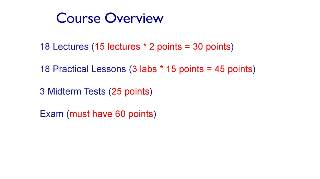
Course Overview18 Lectures (15 lectures * 2 points = 30 points)
18 Practical Lessons (3 labs * 15 points = 45 points)
3 Midterm Tests (25 points)
Exam (must have 60 points)
3.
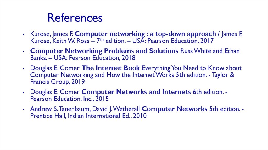
ReferencesKurose, James F. Computer networking : a top-down approach / James F.
Kurose, Keith W. Ross – 7th edition. – USA: Pearson Education, 2017
Computer Networking Problems and Solutions Russ White and Ethan
Banks. – USA: Pearson Education, 2018
Douglas E. Comer The Internet Book Everything You Need to Know about
Computer Networking and How the Internet Works 5th edition. - Taylor &
Francis Group, 2019
Douglas E. Comer Computer Networks and Internets 6th edition. Pearson Education, Inc., 2015
Andrew S. Tanenbaum, David J. Wetherall Computer Networks 5th edition. Prentice Hall, Indian International Ed., 2010
4.
Study ToolsLecture PPTs, Labs, Additional materials:
https://jointvlab.ipt.pt/moodle/
Wireshark, Packet Tracer
5.
Topic 1: introductiongoal:
Overview/roadmap:
Get “feel,” “big picture,”
introduction to terminology
What is the Internet?
What is a protocol?
Network edge: hosts, access network,
physical media
Network core: packet/circuit switching,
internet structure
Performance: loss, delay, throughput
Security
Protocol layers, service models
History
• more depth, detail later in
course
Approach:
• use Internet as example
Introduction: 1-5
6.
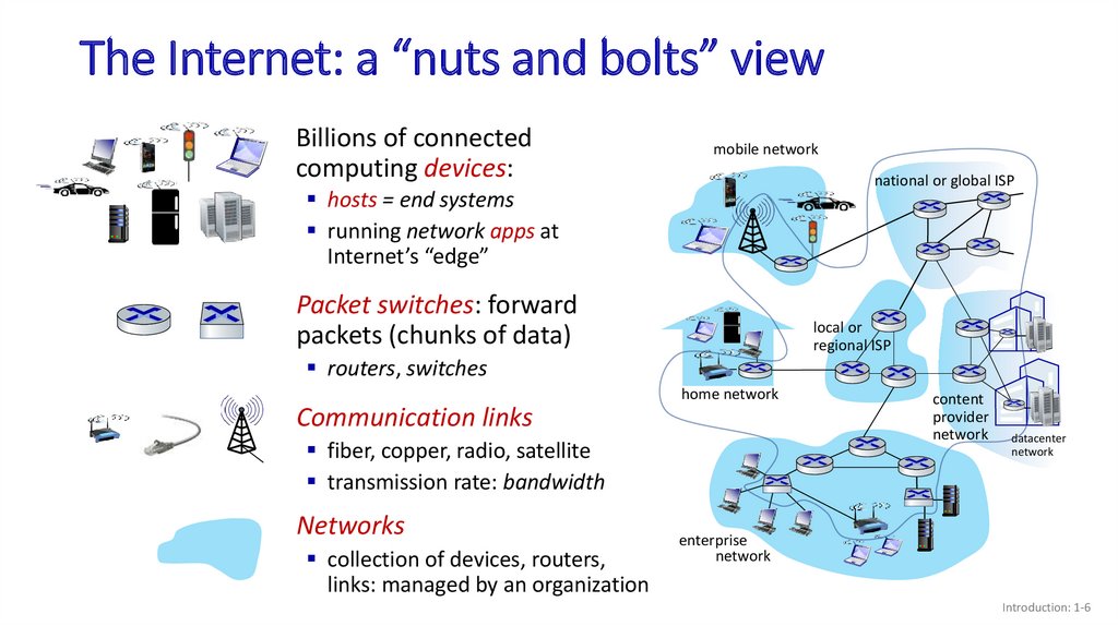
The Internet: a “nuts and bolts” viewBillions of connected
computing devices:
mobile network
national or global ISP
hosts = end systems
running network apps at
Internet’s “edge”
Packet switches: forward
packets (chunks of data)
local or
regional ISP
Internet
routers, switches
home network
Communication links
fiber, copper, radio, satellite
transmission rate: bandwidth
Networks
collection of devices, routers,
links: managed by an organization
content
provider
network
datacenter
network
enterprise
network
Introduction: 1-6
7.
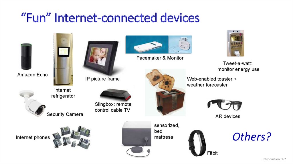
“Fun” Internet-connected devicesPacemaker & Monitor
Tweet-a-watt:
monitor energy use
Amazon Echo
IP picture frame
Web-enabled toaster +
weather forecaster
Internet
refrigerator
Security Camera
Internet phones
Slingbox: remote
control cable TV
AR devices
sensorized,
bed
mattress
Others?
Fitbit
Introduction: 1-7
8.
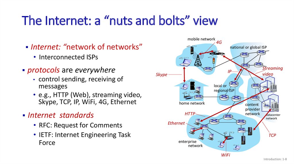
The Internet: a “nuts and bolts” viewmobile network
Internet: “network of networks”
4G
national or global ISP
• Interconnected ISPs
protocols are everywhere
control sending, receiving of
messages
• e.g., HTTP (Web), streaming video,
Skype, TCP, IP, WiFi, 4G, Ethernet
Internet standards
• RFC: Request for Comments
• IETF: Internet Engineering Task
Force
Streaming
video
IP
Skype
local or
regional ISP
home network
content
provider
network
HTTP
datacenter
network
Ethernet
TCP
enterprise
network
WiFi
Introduction: 1-8
9.
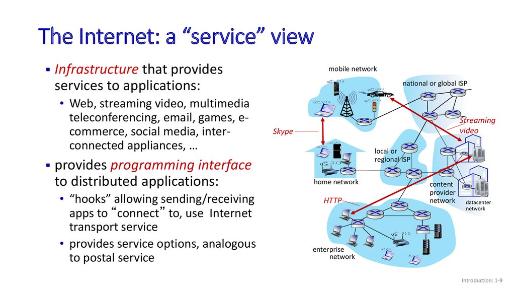
The Internet: a “service” viewInfrastructure that provides
services to applications:
• Web, streaming video, multimedia
teleconferencing, email, games, ecommerce, social media, interconnected appliances, …
provides programming interface
to distributed applications:
• “hooks” allowing sending/receiving
apps to “connect” to, use Internet
transport service
• provides service options, analogous
to postal service
mobile network
national or global ISP
Streaming
video
Skype
local or
regional ISP
home network
HTTP
content
provider
network
datacenter
network
enterprise
network
Introduction: 1-9
10.
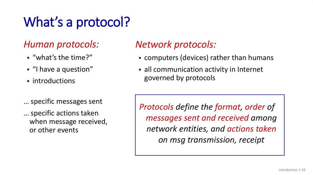
What’s a protocol?Human protocols:
“what’s the time?”
“I have a question”
introductions
… specific messages sent
… specific actions taken
when message received,
or other events
Network protocols:
computers (devices) rather than humans
all communication activity in Internet
governed by protocols
Protocols define the format, order of
messages sent and received among
network entities, and actions taken
on msg transmission, receipt
Introduction: 1-10
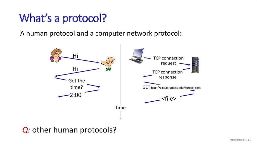
11.
What’s a protocol?A human protocol and a computer network protocol:
Hi
TCP connection
request
Hi
TCP connection
response
Got the
time?
GET http://gaia.cs.umass.edu/kurose_ross
2:00
<file>
time
Q: other human protocols?
Introduction: 1-11
12.
Topic 1: roadmapWhat is the Internet?
What is a protocol?
Network edge: hosts, access network,
physical media
Network core: packet/circuit
switching, internet structure
Performance: loss, delay, throughput
Security
Protocol layers, service models
History
Introduction: 1-12
13.
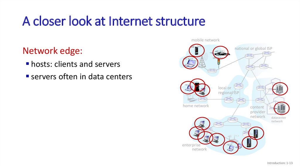
A closer look at Internet structuremobile network
Network edge:
national or global ISP
hosts: clients and servers
servers often in data centers
local or
regional ISP
home network
content
provider
network
datacenter
network
enterprise
network
Introduction: 1-13
14.
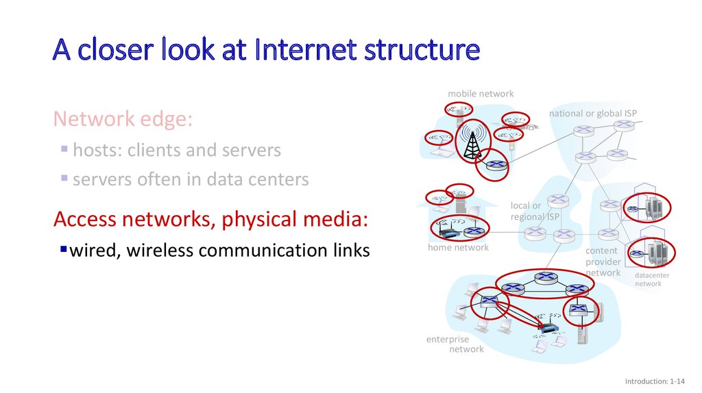
A closer look at Internet structuremobile network
Network edge:
national or global ISP
hosts: clients and servers
servers often in data centers
local or
regional ISP
Access networks, physical media:
wired, wireless communication links
home network
content
provider
network
datacenter
network
enterprise
network
Introduction: 1-14
15.
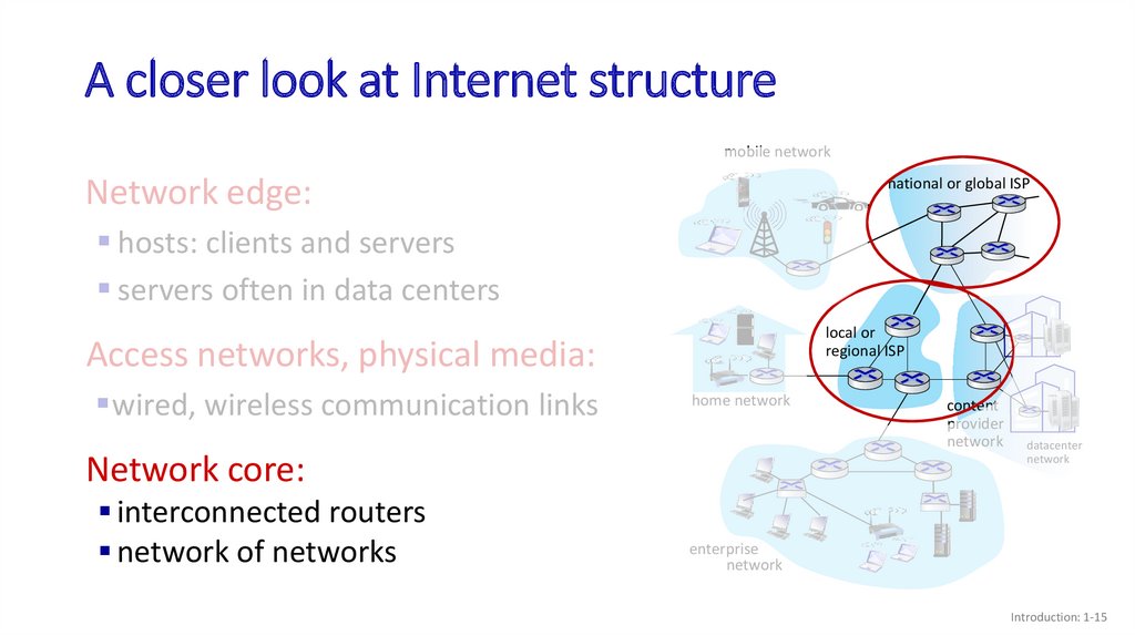
A closer look at Internet structuremobile network
Network edge:
national or global ISP
hosts: clients and servers
servers often in data centers
local or
regional ISP
Access networks, physical media:
wired, wireless communication links
home network
Network core:
interconnected routers
network of networks
content
provider
network
datacenter
network
enterprise
network
Introduction: 1-15
16.
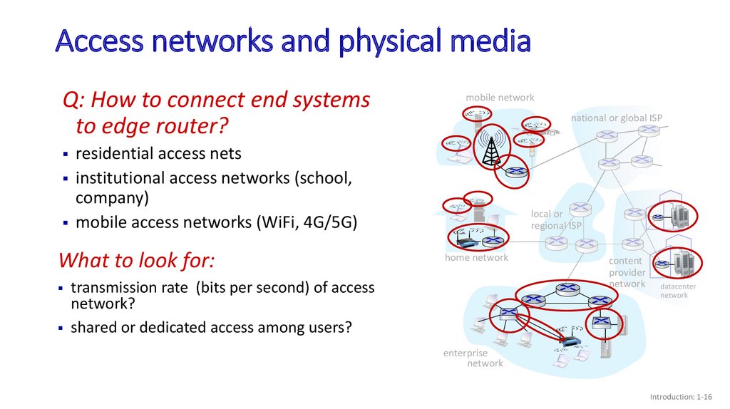
Access networks and physical mediaQ: How to connect end systems
to edge router?
national or global ISP
residential access nets
institutional access networks (school,
company)
mobile access networks (WiFi, 4G/5G)
What to look for:
mobile network
local or
regional ISP
home network
transmission rate (bits per second) of access
network?
shared or dedicated access among users?
content
provider
network
datacenter
network
enterprise
network
Introduction: 1-16
17.
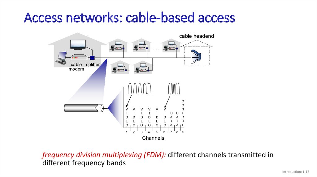
Access networks: cable-based accesscable headend
…
cable splitter
modem
V
I
D
E
O
V
I
D
E
O
V
I
D
E
O
V
I
D
E
O
V
I
D
E
O
V
I
D
E
O
D
A
T
A
D
A
T
A
C
O
N
T
R
O
L
1
2
3
4
5
6
7
8
9
Channels
frequency division multiplexing (FDM): different channels transmitted in
different frequency bands
Introduction: 1-17
18.
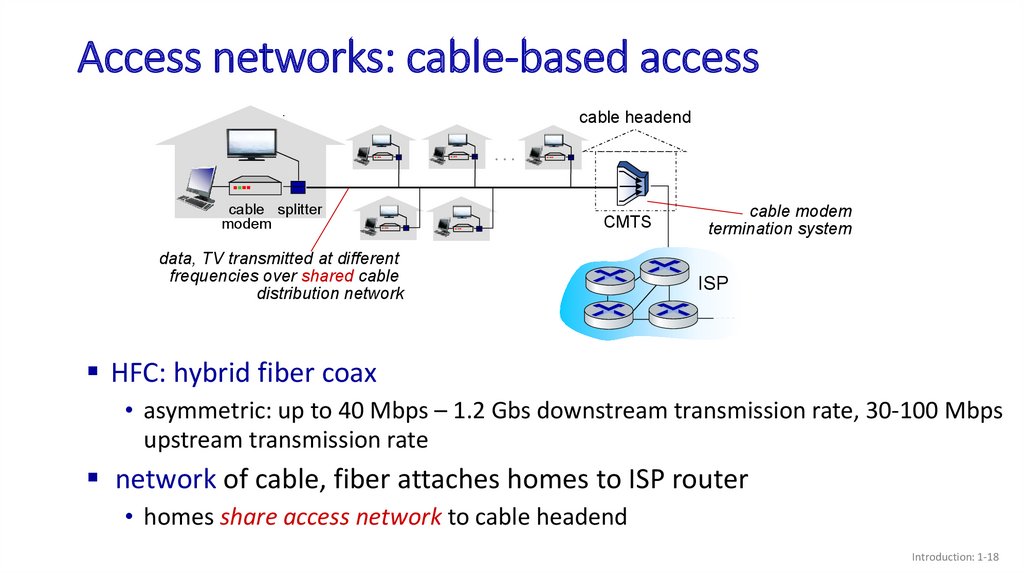
Access networks: cable-based accesscable headend
…
cable splitter
modem
CMTS
data, TV transmitted at different
frequencies over shared cable
distribution network
cable modem
termination system
ISP
HFC: hybrid fiber coax
• asymmetric: up to 40 Mbps – 1.2 Gbs downstream transmission rate, 30-100 Mbps
upstream transmission rate
network of cable, fiber attaches homes to ISP router
• homes share access network to cable headend
Introduction: 1-18
19.
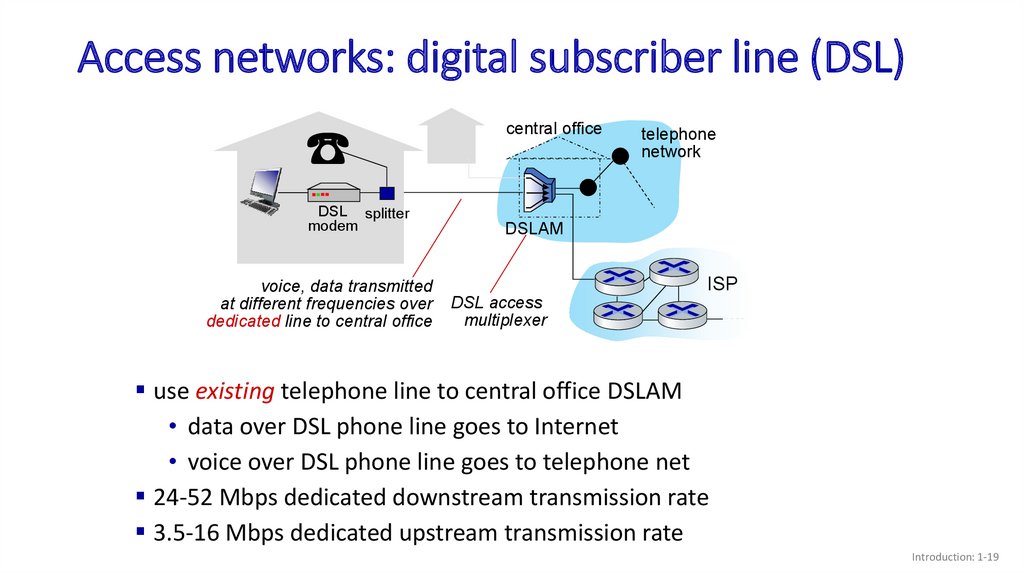
Access networks: digital subscriber line (DSL)central office
DSL splitter
modem
voice, data transmitted
at different frequencies over
dedicated line to central office
telephone
network
DSLAM
ISP
DSL access
multiplexer
use existing telephone line to central office DSLAM
• data over DSL phone line goes to Internet
• voice over DSL phone line goes to telephone net
24-52 Mbps dedicated downstream transmission rate
3.5-16 Mbps dedicated upstream transmission rate
Introduction: 1-19
20.
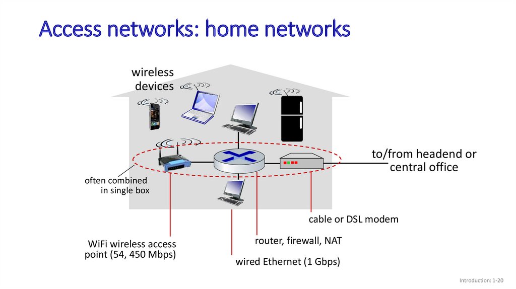
Access networks: home networkswireless
devices
to/from headend or
central office
often combined
in single box
cable or DSL modem
WiFi wireless access
point (54, 450 Mbps)
router, firewall, NAT
wired Ethernet (1 Gbps)
Introduction: 1-20
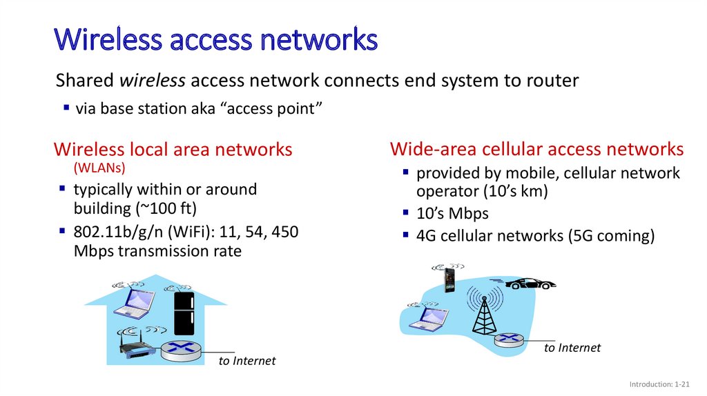
21.
Wireless access networksShared wireless access network connects end system to router
via base station aka “access point”
Wireless local area networks
(WLANs)
typically within or around
building (~100 ft)
802.11b/g/n (WiFi): 11, 54, 450
Mbps transmission rate
to Internet
Wide-area cellular access networks
provided by mobile, cellular network
operator (10’s km)
10’s Mbps
4G cellular networks (5G coming)
to Internet
Introduction: 1-21
22.
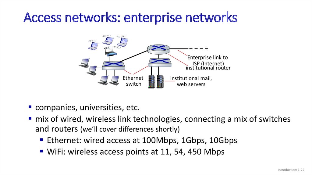
Access networks: enterprise networksEnterprise link to
ISP (Internet)
institutional router
Ethernet
switch
institutional mail,
web servers
companies, universities, etc.
mix of wired, wireless link technologies, connecting a mix of switches
and routers (we’ll cover differences shortly)
Ethernet: wired access at 100Mbps, 1Gbps, 10Gbps
WiFi: wireless access points at 11, 54, 450 Mbps
Introduction: 1-22
23.
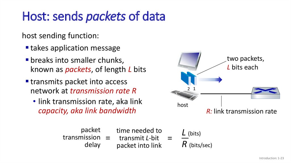
Host: sends packets of datahost sending function:
takes application message
breaks into smaller chunks,
known as packets, of length L bits
transmits packet into access
network at transmission rate R
• link transmission rate, aka link
capacity, aka link bandwidth
packet
transmission
delay
=
time needed to
transmit L-bit
packet into link
two packets,
L bits each
2 1
host
R: link transmission rate
L (bits)
=
R (bits/sec)
Introduction: 1-23
24.
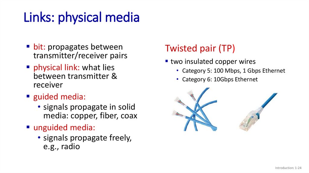
Links: physical mediabit: propagates between
transmitter/receiver pairs
physical link: what lies
between transmitter &
receiver
guided media:
• signals propagate in solid
media: copper, fiber, coax
unguided media:
• signals propagate freely,
e.g., radio
Twisted pair (TP)
two insulated copper wires
• Category 5: 100 Mbps, 1 Gbps Ethernet
• Category 6: 10Gbps Ethernet
Introduction: 1-24
25.
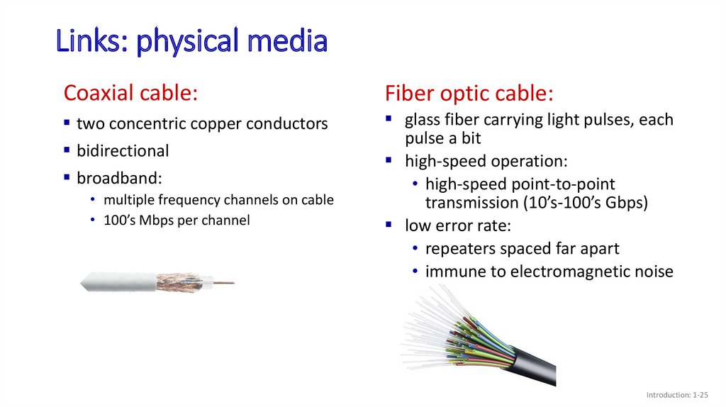
Links: physical mediaCoaxial cable:
Fiber optic cable:
two concentric copper conductors
bidirectional
broadband:
glass fiber carrying light pulses, each
pulse a bit
high-speed operation:
• high-speed point-to-point
transmission (10’s-100’s Gbps)
low error rate:
• repeaters spaced far apart
• immune to electromagnetic noise
• multiple frequency channels on cable
• 100’s Mbps per channel
Introduction: 1-25
26.
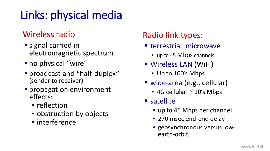
Links: physical mediaWireless radio
Radio link types:
signal carried in
electromagnetic spectrum
no physical “wire”
broadcast and “half-duplex”
terrestrial microwave
(sender to receiver)
propagation environment
effects:
• reflection
• obstruction by objects
• interference
• up to 45 Mbps channels
Wireless LAN (WiFi)
• Up to 100’s Mbps
wide-area (e.g., cellular)
• 4G cellular: ~ 10’s Mbps
satellite
• up to 45 Mbps per channel
• 270 msec end-end delay
• geosynchronous versus lowearth-orbit
Introduction: 1-26
27.
Topic 1: roadmapWhat is the Internet?
What is a protocol?
Network edge: hosts, access network,
physical media
Network core: packet/circuit
switching, internet structure
Performance: loss, delay, throughput
Security
Protocol layers, service models
History
Introduction: 1-27
28.
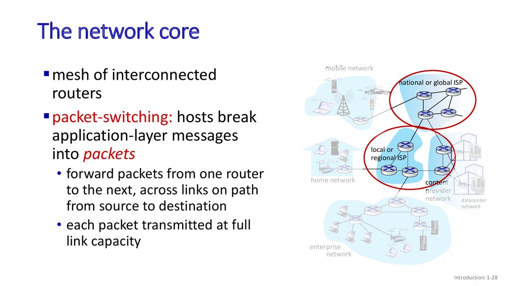
The network coremesh of interconnected
routers
packet-switching: hosts break
application-layer messages
into packets
• forward packets from one router
to the next, across links on path
from source to destination
• each packet transmitted at full
link capacity
mobile network
national or global ISP
local or
regional ISP
home network
content
provider
network
datacenter
network
enterprise
network
Introduction: 1-28
29.
Packet-switching: store-and-forwardL bits
per packet
source
3 2 1
R bps
R bps
Transmission delay: takes L/R seconds to
transmit (push out) L-bit packet into link at R
bps
Store and forward: entire packet must arrive at
router before it can be transmitted on next link
End-end delay: 2L/R (above), assuming zero
propagation delay (more on delay shortly)
destination
One-hop numerical example:
L = 10 Kbits
R = 100 Mbps
one-hop transmission delay
= 0.1 msec
Introduction: 1-29
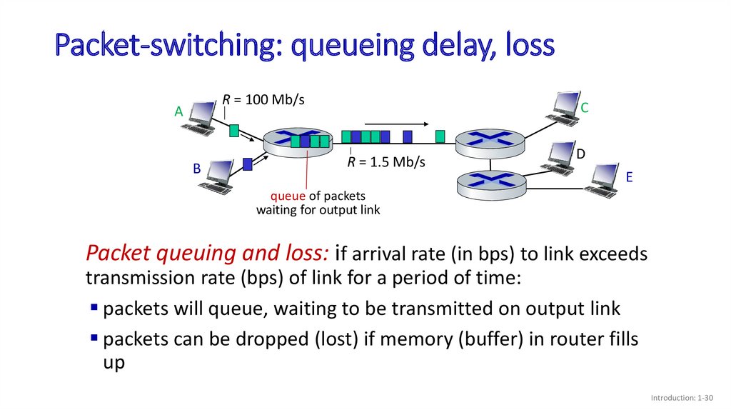
30.
Packet-switching: queueing delay, lossR = 100 Mb/s
A
B
C
R = 1.5 Mb/s
D
E
queue of packets
waiting for output link
Packet queuing and loss: if arrival rate (in bps) to link exceeds
transmission rate (bps) of link for a period of time:
packets will queue, waiting to be transmitted on output link
packets can be dropped (lost) if memory (buffer) in router fills
up
Introduction: 1-30
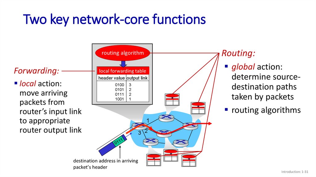
31.
Two key network-core functionsRouting:
routing algorithm
Forwarding:
local
local forwarding
forwarding table
table
local action:
move arriving
packets from
router’s input link
to appropriate
router output link
header value output link
0100
0101
0111
1001
3
2
2
1
global action:
determine sourcedestination paths
taken by packets
routing algorithms
1
3 2
destination address in arriving
packet’s header
Introduction: 1-31
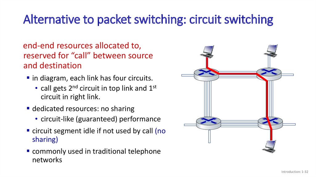
32.
Alternative to packet switching: circuit switchingend-end resources allocated to,
reserved for “call” between source
and destination
in diagram, each link has four circuits.
• call gets 2nd circuit in top link and 1st
circuit in right link.
dedicated resources: no sharing
• circuit-like (guaranteed) performance
circuit segment idle if not used by call (no
sharing)
commonly used in traditional telephone
networks
Introduction: 1-32
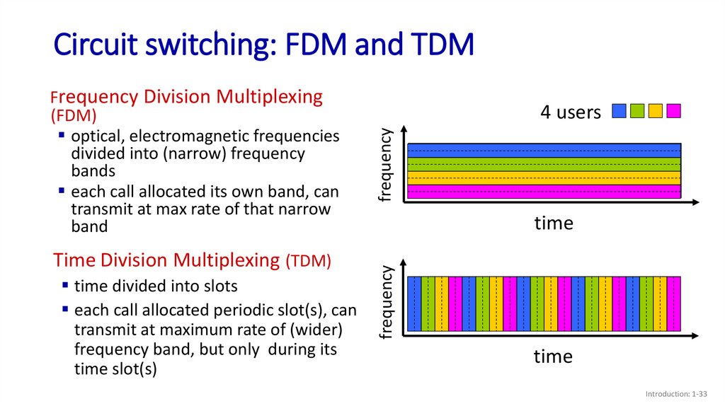
33.
Circuit switching: FDM and TDMTime Division Multiplexing (TDM)
time divided into slots
each call allocated periodic slot(s), can
transmit at maximum rate of (wider)
frequency band, but only during its
time slot(s)
frequency
4 users
time
frequency
Frequency Division Multiplexing
(FDM)
optical, electromagnetic frequencies
divided into (narrow) frequency
bands
each call allocated its own band, can
transmit at max rate of that narrow
band
time
Introduction: 1-33
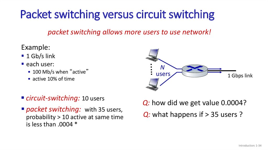
34.
Packet switching versus circuit switchingpacket switching allows more users to use network!
Example:
1 Gb/s link
each user:
• 100 Mb/s when “active”
• active 10% of time
circuit-switching: 10 users
packet switching: with 35 users,
probability > 10 active at same time
is less than .0004 *
N
users
1 Gbps link
Q: how did we get value 0.0004?
Q: what happens if > 35 users ?
Introduction: 1-34
35.
Packet switching versus circuit switchingIs packet switching a “slam dunk winner”?
great for “bursty” data – sometimes has data to send, but at other times not
• resource sharing
• simpler, no call setup
excessive congestion possible: packet delay and loss due to buffer overflow
• protocols needed for reliable data transfer, congestion control
Q: How to provide circuit-like behavior?
• bandwidth guarantees traditionally used for audio/video applications
Q: human analogies of reserved resources (circuit switching)
versus on-demand allocation (packet switching)?
Introduction: 1-35
36.
Internet structure: a “network of networks”Hosts connect to Internet via access Internet Service
Providers (ISPs)
• residential, enterprise (company, university, commercial) ISPs
Access ISPs in turn must be interconnected
• so that any two hosts can send packets to each other
Resulting network of networks is very complex
• evolution was driven by economics and national policies
Let’s take a stepwise approach to describe current
Internet structure
Introduction: 1-36
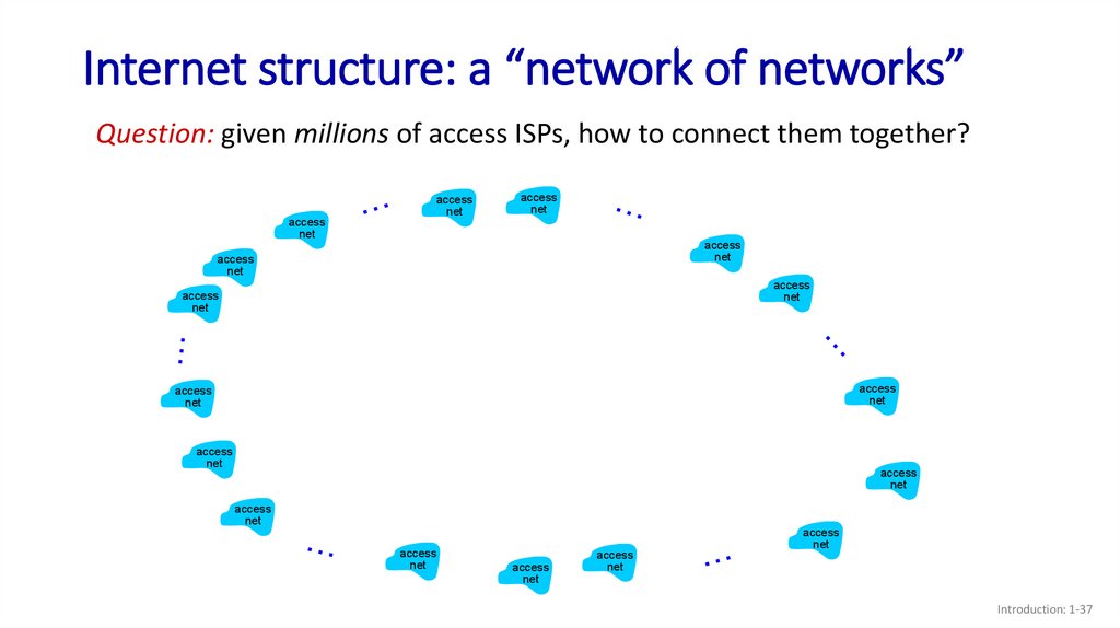
37.
Internet structure: a “network of networks”Question: given millions of access ISPs, how to connect them together?
access
net
access
net
access
net
access
net
access
net
access
net
access
net
access
net
access
net
access
net
access
net
access
net
access
net
access
net
access
net
access
net
Introduction: 1-37
38.
Internet structure: a “network of networks”Question: given millions of access ISPs, how to connect them together?
access
net
access
net
access
net
access
net
access
net
access
net
access
net
connecting each access ISP to
each other directly doesn’t scale:
O(N2) connections.
access
net
access
net
access
net
access
net
access
net
access
net
access
net
access
net
access
net
Introduction: 1-38
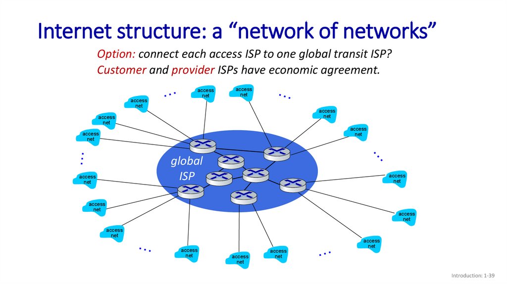
39.
Internet structure: a “network of networks”Option: connect each access ISP to one global transit ISP?
Customer and provider ISPs have economic agreement.
access
net
access
net
access
net
access
net
access
net
access
net
access
net
global
ISP
access
net
access
net
access
net
access
net
access
net
access
net
access
net
access
net
access
net
Introduction: 1-39
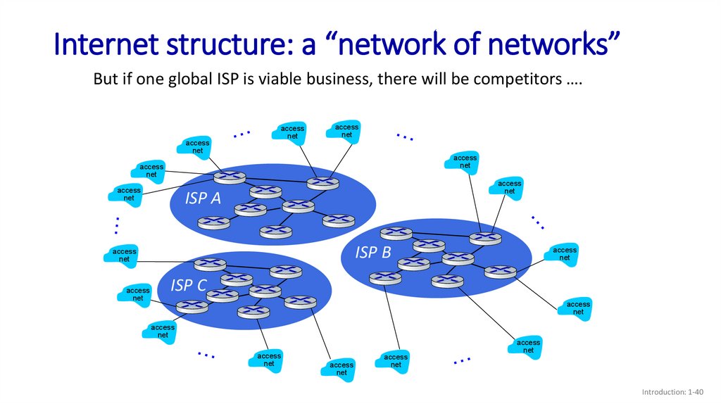
40.
Internet structure: a “network of networks”But if one global ISP is viable business, there will be competitors ….
access
net
access
net
access
net
access
net
access
net
access
net
access
net
ISP A
ISP B
access
net
access
net
access
net
ISP C
access
net
access
net
access
net
access
net
access
net
access
net
Introduction: 1-40
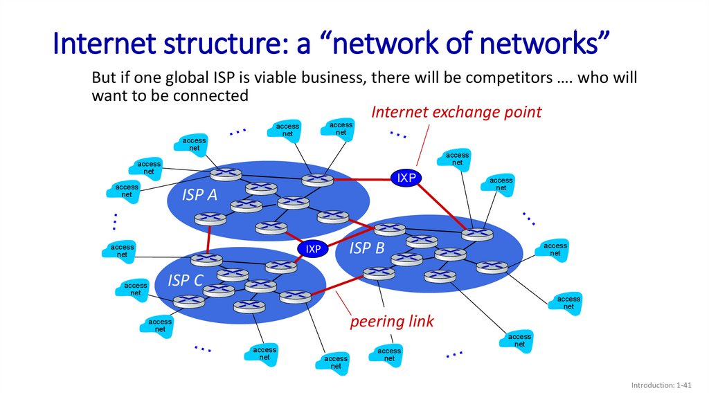
41.
Internet structure: a “network of networks”But if one global ISP is viable business, there will be competitors …. who will
want to be connected
Internet exchange point
access
net
access
net
access
net
access
net
access
net
IXP
access
net
ISP A
access
net
ISP B
IXP
access
net
access
net
access
net
ISP C
access
net
peering link
access
net
access
net
access
net
access
net
access
net
Introduction: 1-41
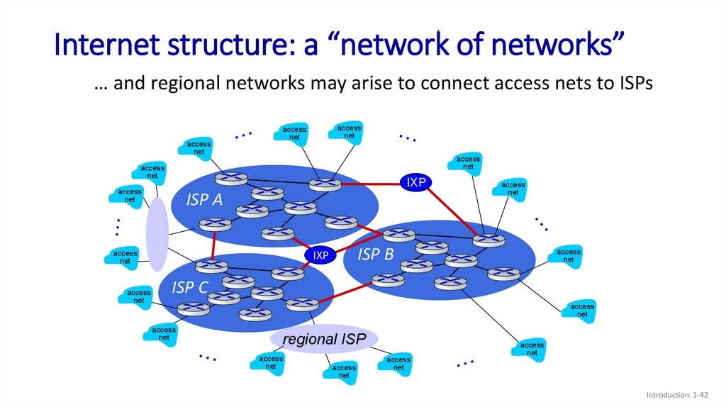
42.
Internet structure: a “network of networks”… and regional networks may arise to connect access nets to ISPs
access
net
access
net
access
net
access
net
access
net
IXP
access
net
ISP A
access
net
ISP B
IXP
access
net
access
net
access
net
ISP C
access
net
access
net
regional ISP
access
net
access
net
access
net
access
net
Introduction: 1-42
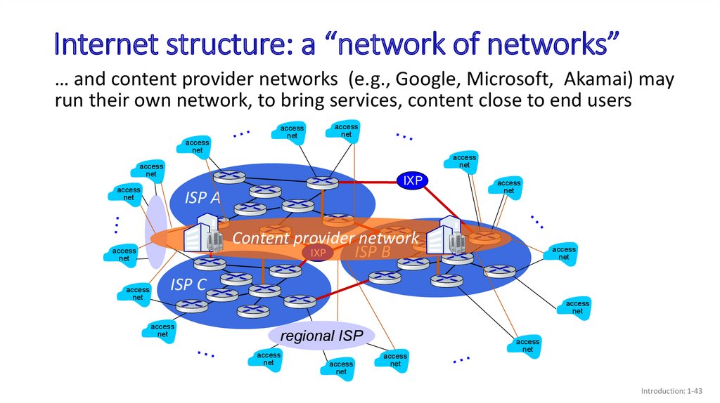
43.
Internet structure: a “network of networks”… and content provider networks (e.g., Google, Microsoft, Akamai) may
run their own network, to bring services, content close to end users
access
net
access
net
access
net
access
net
access
net
IXP
access
net
ISP A
Content provider network
IXP
ISP B
access
net
access
net
access
net
access
net
ISP C
access
net
access
net
regional ISP
access
net
access
net
access
net
access
net
Introduction: 1-43
44.
Internet structure: a “network of networks”Tier 1 ISP
IXP
IXP
Regional ISP
access
ISP
access
ISP
Tier 1 ISP
access
ISP
access
ISP
IXP
Regional ISP
access
ISP
access
ISP
access
ISP
access
ISP
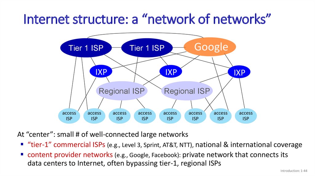
At “center”: small # of well-connected large networks
“tier-1” commercial ISPs (e.g., Level 3, Sprint, AT&T, NTT), national & international coverage
content provider networks (e.g., Google, Facebook): private network that connects its
data centers to Internet, often bypassing tier-1, regional ISPs
Introduction: 1-44
45.
Topic 1: roadmapWhat is the Internet?
What is a protocol?
Network edge: hosts, access network,
physical media
Network core: packet/circuit
switching, internet structure
Performance: loss, delay, throughput
Security
Protocol layers, service models
History
Introduction: 1-45
46.
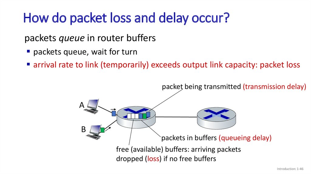
How do packet loss and delay occur?packets queue in router buffers
packets queue, wait for turn
arrival rate to link (temporarily) exceeds output link capacity: packet loss
packet being transmitted (transmission delay)
A
B
packets in buffers (queueing delay)
free (available) buffers: arriving packets
dropped (loss) if no free buffers
Introduction: 1-46
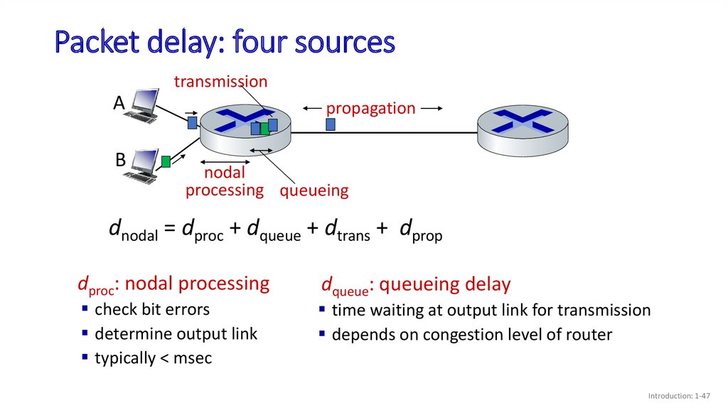
47.
Packet delay: four sourcestransmission
A
B
propagation
nodal
processing queueing
dnodal = dproc + dqueue + dtrans + dprop
dproc: nodal processing
check bit errors
determine output link
typically < msec
dqueue: queueing delay
time waiting at output link for transmission
depends on congestion level of router
Introduction: 1-47
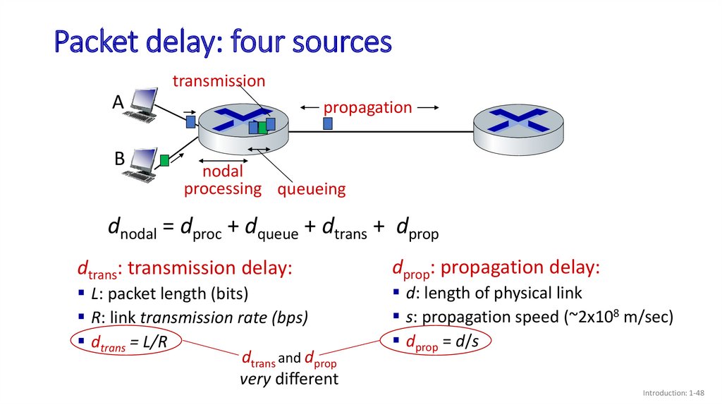
48.
Packet delay: four sourcestransmission
A
B
propagation
nodal
processing queueing
dnodal = dproc + dqueue + dtrans + dprop
dtrans: transmission delay:
L: packet length (bits)
R: link transmission rate (bps)
dtrans = L/R
dtrans and dprop
very different
dprop: propagation delay:
d: length of physical link
s: propagation speed (~2x10⁸ m/sec)
dprop = d/s
Introduction: 1-48
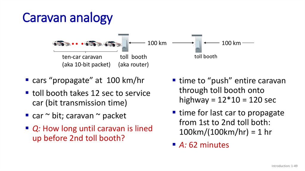
49.
Caravan analogy100 km
ten-car caravan
(aka 10-bit packet)
toll booth
(aka router)
cars “propagate” at 100 km/hr
toll booth takes 12 sec to service
car (bit transmission time)
car ~ bit; caravan ~ packet
Q: How long until caravan is lined
up before 2nd toll booth?
100 km
toll booth
time to “push” entire caravan
through toll booth onto
highway = 12*10 = 120 sec
time for last car to propagate
from 1st to 2nd toll both:
100km/(100km/hr) = 1 hr
A: 62 minutes
Introduction: 1-49
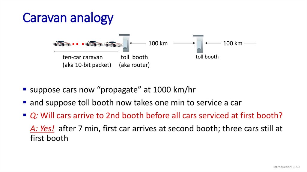
50.
Caravan analogy100 km
ten-car caravan
(aka 10-bit packet)
toll booth
(aka router)
100 km
toll booth
suppose cars now “propagate” at 1000 km/hr
and suppose toll booth now takes one min to service a car
Q: Will cars arrive to 2nd booth before all cars serviced at first booth?
A: Yes! after 7 min, first car arrives at second booth; three cars still at
first booth
Introduction: 1-50
51.
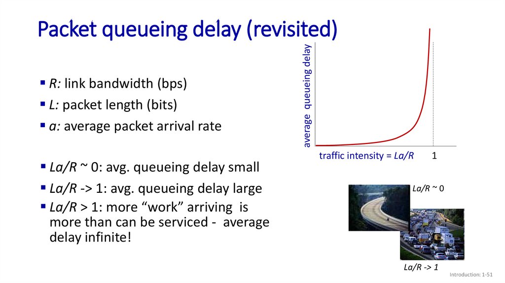
R: link bandwidth (bps)L: packet length (bits)
a: average packet arrival rate
La/R ~ 0: avg. queueing delay small
La/R -> 1: avg. queueing delay large
La/R > 1: more “work” arriving is
more than can be serviced - average
delay infinite!
average queueing delay
Packet queueing delay (revisited)
traffic intensity = La/R
1
La/R ~ 0
La/R -> 1
Introduction: 1-51
52.
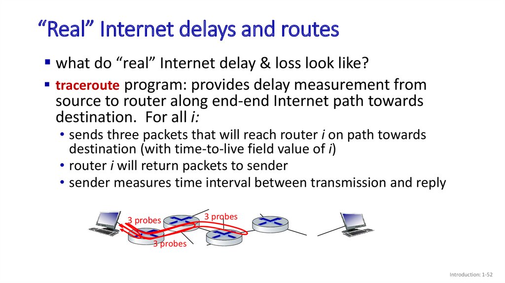
“Real” Internet delays and routeswhat do “real” Internet delay & loss look like?
traceroute program: provides delay measurement from
source to router along end-end Internet path towards
destination. For all i:
• sends three packets that will reach router i on path towards
destination (with time-to-live field value of i)
• router i will return packets to sender
• sender measures time interval between transmission and reply
3 probes
3 probes
3 probes
Introduction: 1-52
53.
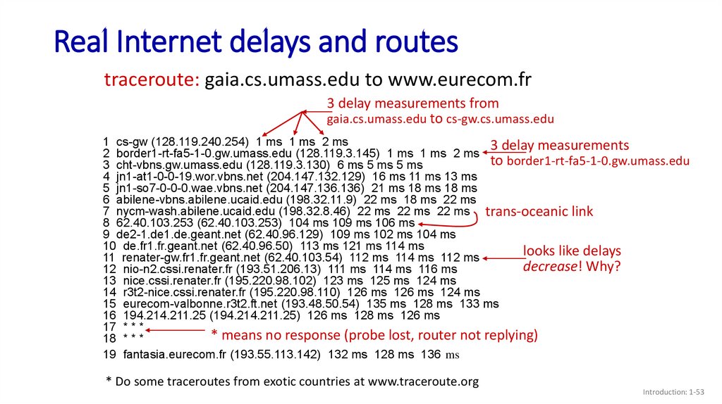
Real Internet delays and routestraceroute: gaia.cs.umass.edu to www.eurecom.fr
3 delay measurements from
gaia.cs.umass.edu to cs-gw.cs.umass.edu
1 cs-gw (128.119.240.254) 1 ms 1 ms 2 ms
3 delay measurements
2 border1-rt-fa5-1-0.gw.umass.edu (128.119.3.145) 1 ms 1 ms 2 ms
to border1-rt-fa5-1-0.gw.umass.edu
3 cht-vbns.gw.umass.edu (128.119.3.130) 6 ms 5 ms 5 ms
4 jn1-at1-0-0-19.wor.vbns.net (204.147.132.129) 16 ms 11 ms 13 ms
5 jn1-so7-0-0-0.wae.vbns.net (204.147.136.136) 21 ms 18 ms 18 ms
6 abilene-vbns.abilene.ucaid.edu (198.32.11.9) 22 ms 18 ms 22 ms
7 nycm-wash.abilene.ucaid.edu (198.32.8.46) 22 ms 22 ms 22 ms trans-oceanic link
8 62.40.103.253 (62.40.103.253) 104 ms 109 ms 106 ms
9 de2-1.de1.de.geant.net (62.40.96.129) 109 ms 102 ms 104 ms
10 de.fr1.fr.geant.net (62.40.96.50) 113 ms 121 ms 114 ms
looks like delays
11 renater-gw.fr1.fr.geant.net (62.40.103.54) 112 ms 114 ms 112 ms
decrease! Why?
12 nio-n2.cssi.renater.fr (193.51.206.13) 111 ms 114 ms 116 ms
13 nice.cssi.renater.fr (195.220.98.102) 123 ms 125 ms 124 ms
14 r3t2-nice.cssi.renater.fr (195.220.98.110) 126 ms 126 ms 124 ms
15 eurecom-valbonne.r3t2.ft.net (193.48.50.54) 135 ms 128 ms 133 ms
16 194.214.211.25 (194.214.211.25) 126 ms 128 ms 126 ms
17 * * *
* means no response (probe lost, router not replying)
18 * * *
19 fantasia.eurecom.fr (193.55.113.142) 132 ms 128 ms 136 ms
* Do some traceroutes from exotic countries at www.traceroute.org
Introduction: 1-53
54.
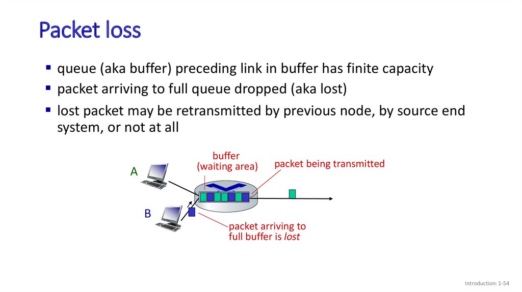
Packet lossqueue (aka buffer) preceding link in buffer has finite capacity
packet arriving to full queue dropped (aka lost)
lost packet may be retransmitted by previous node, by source end
system, or not at all
buffer
(waiting area)
A
packet being transmitted
B
packet arriving to
full buffer is lost
Introduction: 1-54
55.
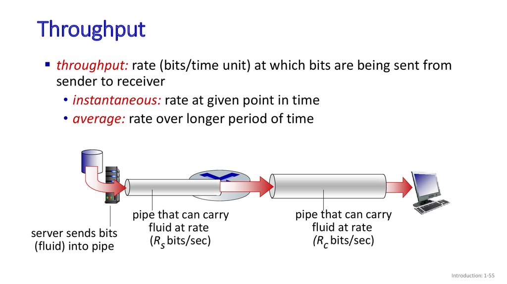
Throughputthroughput: rate (bits/time unit) at which bits are being sent from
sender to receiver
• instantaneous: rate at given point in time
• average: rate over longer period of time
link capacity
pipe
that can carry
Rsfluid
bits/sec
at rate
serverserver,
sends with
bits
(Rs bits/sec)
(fluid)
into
pipe
file of F bits
to send to client
linkthat
capacity
pipe
can carry
Rfluid
at rate
c bits/sec
(Rc bits/sec)
Introduction: 1-55
56.
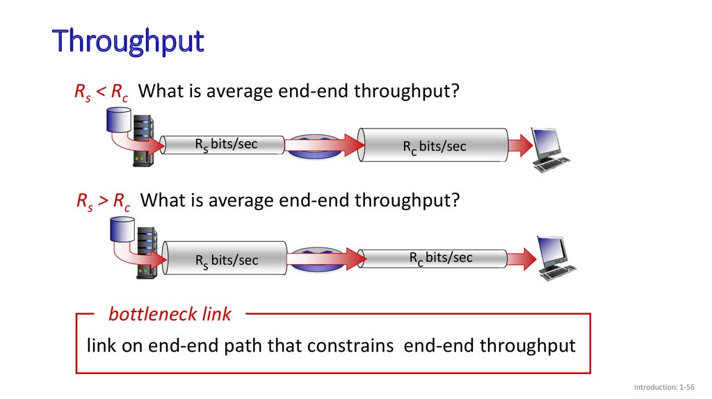
ThroughputRs < Rc What is average end-end throughput?
Rs bits/sec
Rc bits/sec
Rs > Rc What is average end-end throughput?
Rs bits/sec
Rc bits/sec
bottleneck link
link on end-end path that constrains end-end throughput
Introduction: 1-56
57.
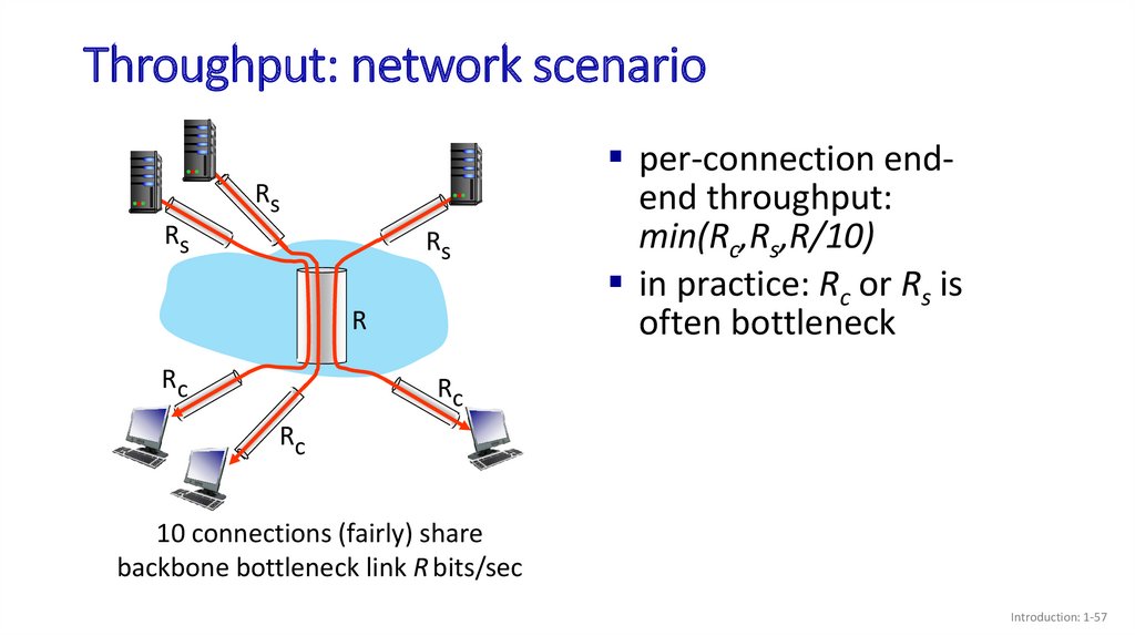
Throughput: network scenarioRs
Rs
Rs
R
Rc
per-connection endend throughput:
min(Rc,Rs,R/10)
in practice: Rc or Rs is
often bottleneck
Rc
Rc
10 connections (fairly) share
backbone bottleneck link R bits/sec
Introduction: 1-57
58.
Topic 1: roadmapWhat is the Internet?
What is a protocol?
Network edge: hosts, access network,
physical media
Network core: packet/circuit
switching, internet structure
Performance: loss, delay, throughput
Security
Protocol layers, service models
History
Introduction: 1-58
59.
Network securityfield of network security:
• how bad guys can attack computer networks
• how we can defend networks against attacks
• how to design architectures that are immune to attacks
Internet not originally designed with (much) security in
mind
• original vision: “a group of mutually trusting users attached to a
transparent network”
• Internet protocol designers playing “catch-up”
• security considerations in all layers!
Introduction: 1-59
60.
Bad guys: malwaremalware can get in host from:
• virus: self-replicating infection by receiving/executing object
(e.g., e-mail attachment)
• worm: self-replicating infection by passively receiving object that
gets itself executed
spyware malware can record keystrokes, web sites visited, upload
info to collection site
infected host can be enrolled in botnet, used for spam or
distributed denial of service (DDoS) attacks
Introduction: 1-60
61.
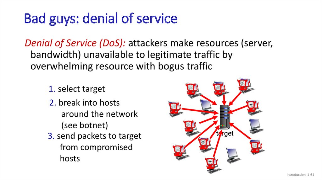
Bad guys: denial of serviceDenial of Service (DoS): attackers make resources (server,
bandwidth) unavailable to legitimate traffic by
overwhelming resource with bogus traffic
1. select target
2. break into hosts
around the network
(see botnet)
3. send packets to target
from compromised
hosts
target
Introduction: 1-61
62.
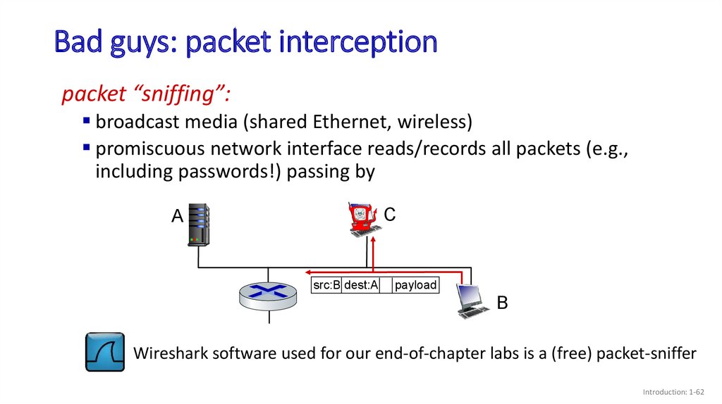
Bad guys: packet interceptionpacket “sniffing”:
broadcast media (shared Ethernet, wireless)
promiscuous network interface reads/records all packets (e.g.,
including passwords!) passing by
C
A
src:B dest:A
payload
B
Wireshark software used for our end-of-chapter labs is a (free) packet-sniffer
Introduction: 1-62
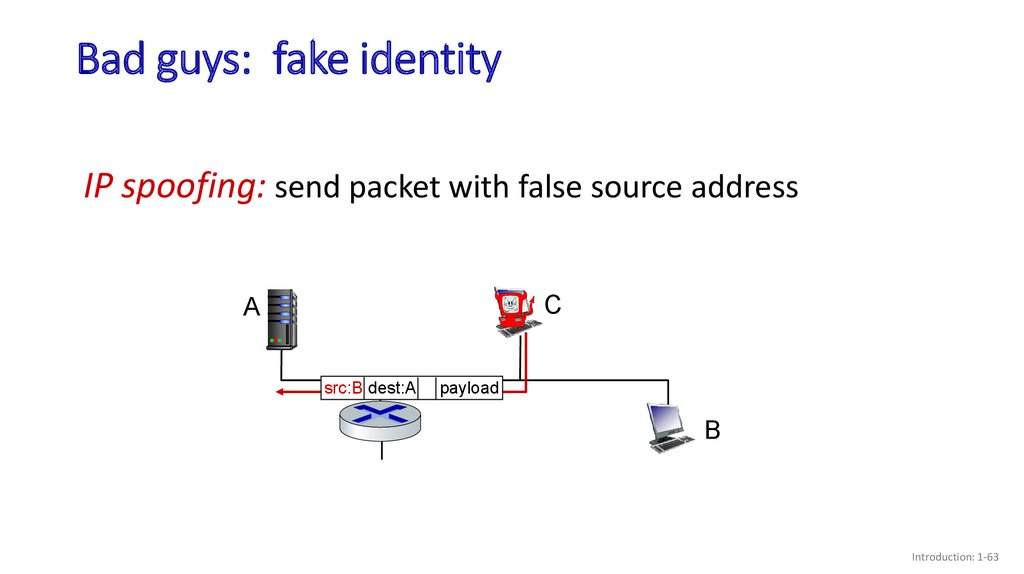
63.
Bad guys: fake identityIP spoofing: send packet with false source address
C
A
src:B dest:A
payload
B
Introduction: 1-63
64.
Topic 1: roadmapWhat is the Internet?
What is a protocol?
Network edge: hosts, access network,
physical media
Network core: packet/circuit
switching, internet structure
Performance: loss, delay, throughput
Security
Protocol layers, service models
History
Introduction: 1-64
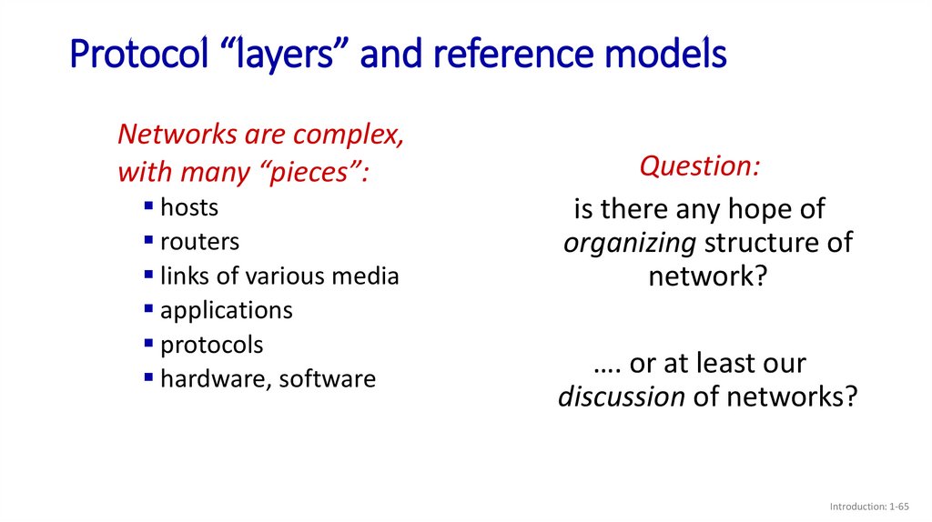
65.
Protocol “layers” and reference modelsNetworks are complex,
with many “pieces”:
hosts
routers
links of various media
applications
protocols
hardware, software
Question:
is there any hope of
organizing structure of
network?
…. or at least our
discussion of networks?
Introduction: 1-65
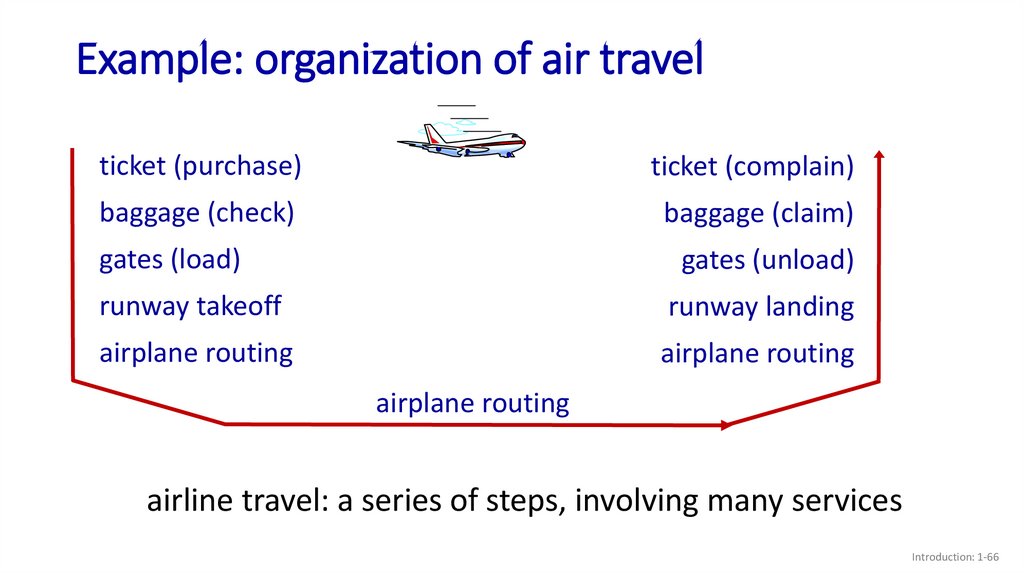
66.
Example: organization of air travelticket (purchase)
ticket (complain)
baggage (check)
baggage (claim)
gates (load)
gates (unload)
runway takeoff
runway landing
airplane routing
airplane routing
airplane routing
airline travel: a series of steps, involving many services
Introduction: 1-66
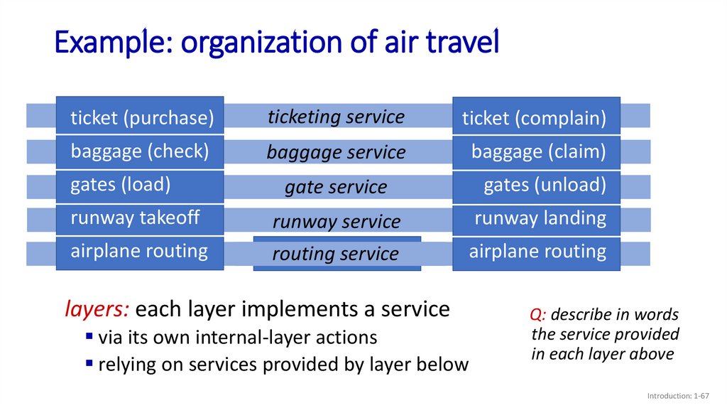
67.
Example: organization of air travelticket (purchase)
ticketing service
ticket (complain)
baggage (check)
baggage service
baggage (claim)
gate service
gates (unload)
runway takeoff
runway service
runway landing
airplane routing
routing service
airplane
routing
airplane routing
gates (load)
layers: each layer implements a service
via its own internal-layer actions
relying on services provided by layer below
Q: describe in words
the service provided
in each layer above
Introduction: 1-67
68.
Why layering?dealing with complex systems:
explicit structure allows identification, relationship of
complex system’s pieces
• layered reference model for discussion
modularization eases maintenance, updating of system
• change in layer's service implementation: transparent to rest of
system
• e.g., change in gate procedure doesn’t affect rest of system
layering considered harmful?
layering in other complex systems?
Introduction: 1-68
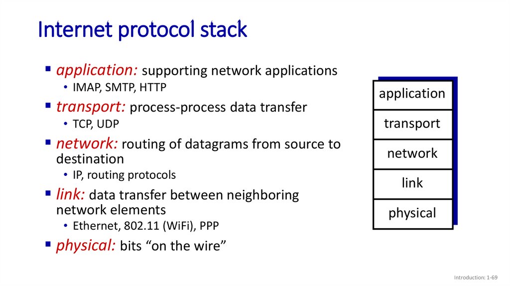
69.
Internet protocol stackapplication: supporting network applications
• IMAP, SMTP, HTTP
transport: process-process data transfer
• TCP, UDP
network: routing of datagrams from source to
destination
• IP, routing protocols
link: data transfer between neighboring
network elements
• Ethernet, 802.11 (WiFi), PPP
application
transport
network
link
physical
physical: bits “on the wire”
Introduction: 1-69
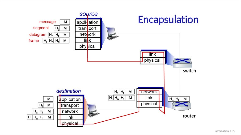
70.
sourcemessage
segment
M
Ht
M
datagram Hn Ht
M
frame
M
Hl Hn Ht
Encapsulation
application
transport
network
link
physical
link
physical
switch
M
Ht
M
Hn Ht
M
Hl Hn Ht
M
destination
Hn Ht
M
application
transport
network
link
physical
Hl Hn Ht
M
network
link
physical
Hn Ht
M
router
Introduction: 1-70
71.
Topic 1: roadmapWhat is the Internet?
What is a protocol?
Network edge: hosts, access network,
physical media
Network core: packet/circuit
switching, internet structure
Performance: loss, delay, throughput
Security
Protocol layers, service models
History
Introduction: 1-71
72.
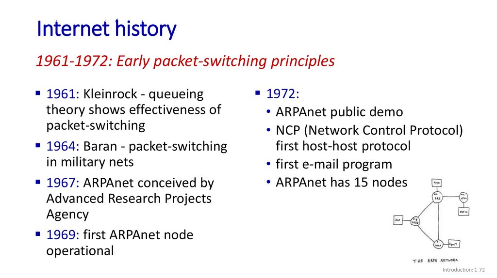
Internet history1961-1972: Early packet-switching principles
1961: Kleinrock - queueing
theory shows effectiveness of
packet-switching
1964: Baran - packet-switching
in military nets
1967: ARPAnet conceived by
Advanced Research Projects
Agency
1969: first ARPAnet node
operational
1972:
• ARPAnet public demo
• NCP (Network Control Protocol)
first host-host protocol
• first e-mail program
• ARPAnet has 15 nodes
Introduction: 1-72
73.
Internet history1972-1980: Internetworking, new and proprietary nets
1970: ALOHAnet satellite network
in Hawaii
1974: Cerf and Kahn - architecture
for interconnecting networks
1976: Ethernet at Xerox PARC
late70’s: proprietary architectures:
DECnet, SNA, XNA
late 70’s: switching fixed length
packets (ATM precursor)
1979: ARPAnet has 200 nodes
Cerf and Kahn’s internetworking
principles:
minimalism, autonomy - no
internal changes required to
interconnect networks
best-effort service model
stateless routing
decentralized control
define today’s Internet architecture
Introduction: 1-73
74.
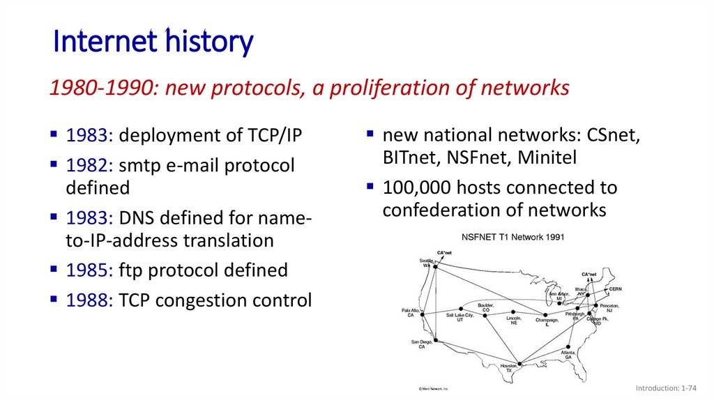
Internet history1980-1990: new protocols, a proliferation of networks
1983: deployment of TCP/IP
1982: smtp e-mail protocol
defined
1983: DNS defined for nameto-IP-address translation
1985: ftp protocol defined
1988: TCP congestion control
new national networks: CSnet,
BITnet, NSFnet, Minitel
100,000 hosts connected to
confederation of networks
Introduction: 1-74
75.
Internet history1990, 2000s: commercialization, the Web, new applications
early 1990s: ARPAnet
decommissioned
1991: NSF lifts restrictions on
commercial use of NSFnet
(decommissioned, 1995)
early 1990s: Web
hypertext [Bush 1945, Nelson 1960’s]
HTML, HTTP: Berners-Lee
1994: Mosaic, later Netscape
late 1990s: commercialization of the
late 1990s – 2000s:
more killer apps: instant
messaging, P2P file sharing
network security to forefront
est. 50 million host, 100 million+
users
backbone links running at Gbps
Web
Introduction: 1-75
76.
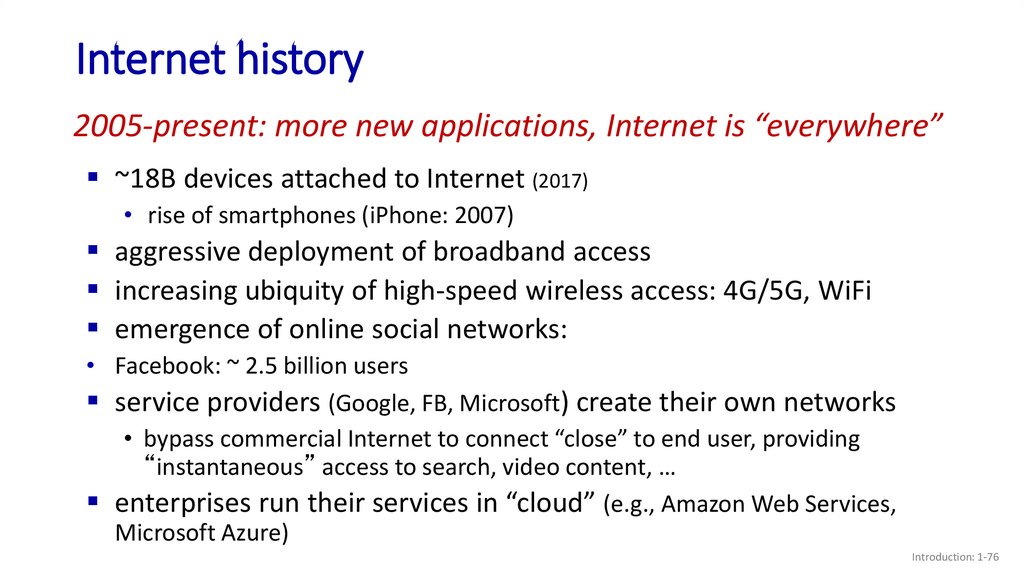
Internet history2005-present: more new applications, Internet is “everywhere”
~18B devices attached to Internet (2017)
• rise of smartphones (iPhone: 2007)
aggressive deployment of broadband access
increasing ubiquity of high-speed wireless access: 4G/5G, WiFi
emergence of online social networks:
• Facebook: ~ 2.5 billion users
service providers (Google, FB, Microsoft) create their own networks
• bypass commercial Internet to connect “close” to end user, providing
“instantaneous” access to search, video content, …
enterprises run their services in “cloud” (e.g., Amazon Web Services,
Microsoft Azure)
Introduction: 1-76
77.
Topic 1: summaryWe’ve covered a “ton” of material!
Internet overview
what’s a protocol?
network edge, access network, core
• packet-switching versus circuitswitching
• Internet structure
performance: loss, delay, throughput
layering, service models
security
history
You now have:
context, overview,
vocabulary, “feel”
of networking
more depth,
detail, and fun to
follow!
Introduction: 1-77
78.
Additional Topic 1 slidesIntroduction: 1-78
79.
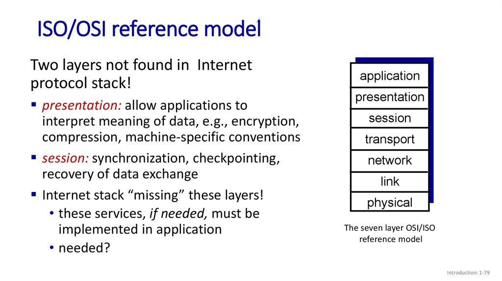
ISO/OSI reference modelTwo layers not found in Internet
protocol stack!
presentation: allow applications to
interpret meaning of data, e.g., encryption,
compression, machine-specific conventions
session: synchronization, checkpointing,
recovery of data exchange
Internet stack “missing” these layers!
• these services, if needed, must be
implemented in application
• needed?
application
presentation
session
transport
network
link
physical
The seven layer OSI/ISO
reference model
Introduction: 1-79
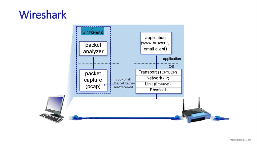
80.
Wiresharkapplication
(www browser,
email client)
packet
analyzer
application
packet
capture
(pcap)
OS
Transport (TCP/UDP)
copy of all
Ethernet frames
sent/received
Network (IP)
Link (Ethernet)
Physical
Introduction: 1-80