 Промышленность
Похожие презентации:


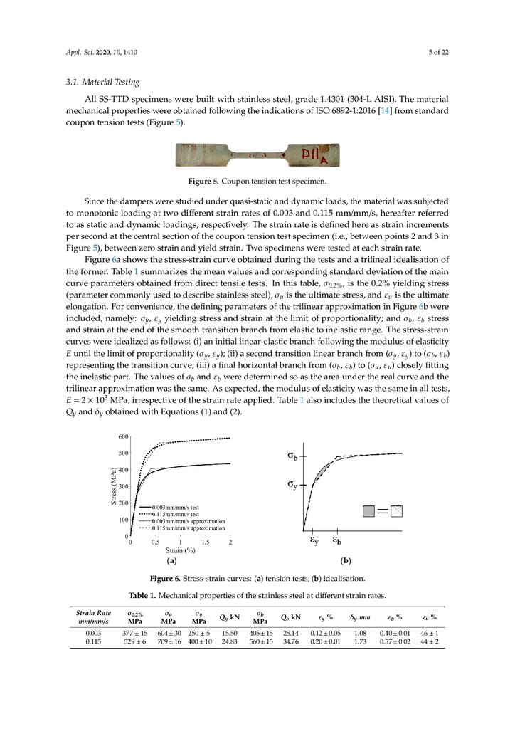
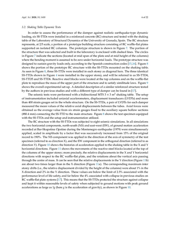
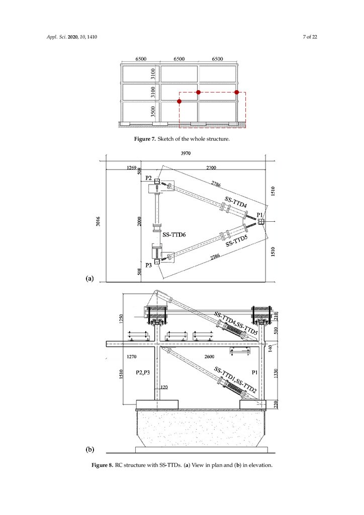
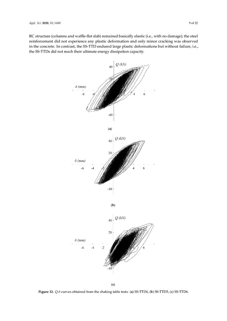
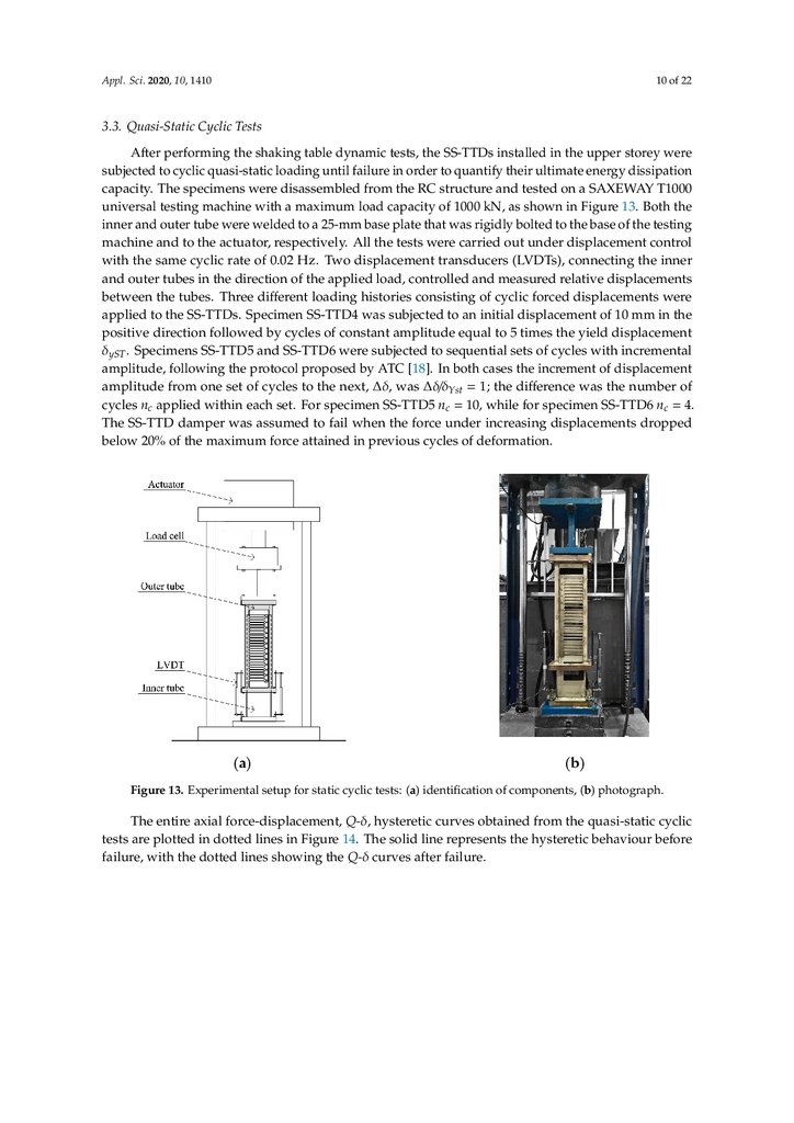
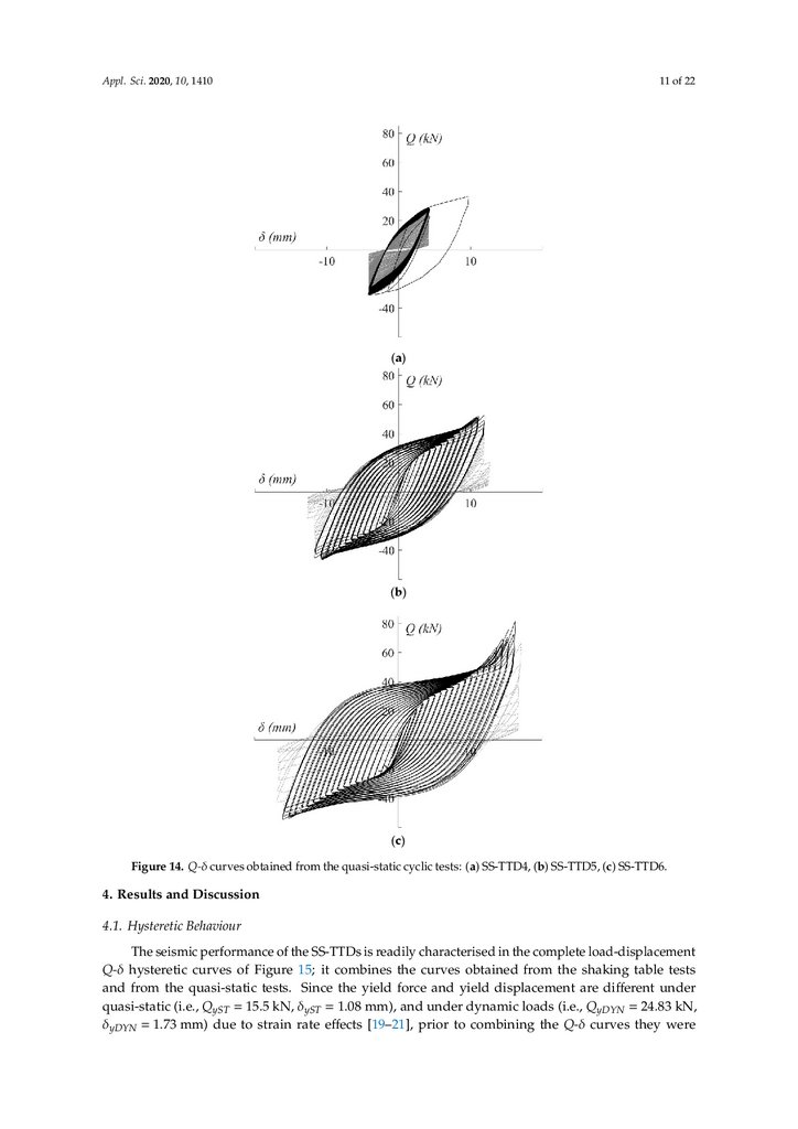
A New Stainless-Steel Tube-in-Tube Damper for Seismic Protection of Structures
1.
appliedsciences
Article
A New Stainless-Steel Tube-in-Tube Damper for
Seismic Protection of Structures
Guillermo González-Sanz , David Escolano-Margarit
and Amadeo Benavent-Climent *
Department of Mechanical Engineering, Universidad Politécnica de Madrid, 28006 Madrid, Spain;
[email protected] (G.G.-S.); [email protected] (D.E.-M.)
* Correspondence: [email protected]; Tel.: +34-910-677-237
Received: 1 February 2020; Accepted: 17 February 2020; Published: 19 February 2020
Featured Application: The damper presented in this paper is applied for the protection of buildings
subjected to strong earthquakes; in particular, for preventing or minimizing damage to the main
structure and reducing its lateral displacements.
Abstract: This paper investigates a new stainless-steel tube-in-tube damper (SS-TTD) designed for
the passive control of structures subjected to seismic loadings. It consists of two tubes assembled
in a telescopic configuration. A series of slits are cut on the walls of the exterior tube in order to
create a series of strips with a large height-to-width ratio. The exterior tube is connected to the
interior tube so that when the brace-type damper is subjected to forced axial displacements, the strips
dissipate energy in the form of flexural plastic deformations. The performance of the SS-TTD is
assessed experimentally through quasi-static and dynamic shaking table tests. Its ultimate energy
dissipation capacity is quantitatively evaluated, and a procedure is proposed to predict the failure.
The cumulative ductility of the SS-TTD is about 4-fold larger than that reported for other dampers
based on slit-type plates in previous studies. Its ultimate energy dissipation capacity is 3- and 16-fold
higher than that of slit-type plates made of mild steel and high-strength steel, respectively. Finally,
two hysteretic models are investigated and compared to characterise the hysteretic behaviour of the
SS-TTD under arbitrarily applied cyclic loads.
Keywords: metallic damper; stainless steel; shaking table test; cyclic loading; energy dissipation
1. Introduction
For decades, seismic-resistant structures have been designed using the conventional approach of
ensuring life safety against earthquakes, the main objective being to prevent buildings from collapsing.
However, this approach comes at the cost of assuming important damage to the structure after the
earthquake, requiring in most cases its demolition and rebuilding or a high cost of repair. Strong ground
motions such as the Northridge (Northridge, 1994) or Hyogo-ken Nambu (Kobe, 1995) earthquakes
have long since proven that this approach is no longer valid, as economic losses are also to be considered
in seismic-resistant design. Controlling damage is a key aspect of the so-called Performance-Based
Seismic Design: the new paradigm that has guided the development of codes, strategies and new
technologies in the earthquake engineering field since the beginning of this century.
Substantial research efforts have been devoted to the development of innovative systems to
control structures’ vibration. These are categorized into four groups: passive systems, active systems,
semi-active systems and hybrid systems [1–4]. Among them, passive control systems based on the use of
displacement-dependent energy dissipation devices (EDDs)—also referred to herein as dampers—have
been proven to be a cost-effective solution. When installed in the main structure, they can enhance the
overall performance of the building, reducing the seismic response in terms of displacements and,
Appl. Sci. 2020, 10, 1410; doi:10.3390/app10041410
www.mdpi.com/journal/applsci
2.
Appl.Appl.Sci. Sci.
2020,
10, 10,
1410
2020,
1410
of 22
2 of2 23
can enhance the overall performance of the building, reducing the seismic response in terms of
more
importantly,and,
attracting
most of the energy
input
by of
thethe
earthquake.
Thebydamage
concentrates
displacements
more importantly,
attracting
most
energy input
the earthquake.
The in
the damage
EDDs, which
are
specifically
engineered
elements
easy
to
inspect,
repair
and/or
replace
after
concentrates in the EDDs, which are specifically engineered elements easy to inspect, repairan
earthquake.
This prevents
to theThis
main
structure
and minimizes
disruption
onand
the building
and/or replace
after an damage
earthquake.
prevents
damage
to the main
structure
minimizesuse.
In
displacement-dependent
dampers,
energy
is
dissipated
through
different
mechanisms:
metal
disruption on the building use.
yielding,Inmetal
phase
transformation,
friction,
sliding,
etc.
Dampers
based
on
metal
yielding
(metallic
displacement-dependent dampers, energy is dissipated through different mechanisms: metal
dampers)
are
made
of materials
with afriction,
large inherent
plastic
deformation
capacity
and (metallic
shaped to
yielding,
metal
phase
transformation,
sliding, etc.
Dampers
based on metal
yielding
dampers)
are made
of materials
with a that
largecould
inherent
plastic deformation
and shaped
to
avoid
any source
of stress
concentration
jeopardise
the inherentcapacity
high energy
dissipation
avoid
any
source
of
stress
concentration
that
could
jeopardise
the
inherent
high
energy
dissipation
capacity of the material. Many metallic dampers have been developed in the last decades, and a
capacity of the
material.
Many metallic
dampers
have
beenindeveloped
in the lastdesigns
decades,
and based
a state-on
state-of-the-art
review
of metallic
dampers
can be
found
[5]. The original
were
of-the-art
review
of metallic
dampers
canand
be found
in [5].
The originalofdesigns
were
basedSome
on simple
simple
torsion
or bending
of steel
plates
uniaxial
deformation
U-shape
strips.
widely
torsion
or
bending
of
steel
plates
and
uniaxial
deformation
of
U-shape
strips.
Some
widely
used
used examples are: Buckling Restrained Braces, Added Damping and Stiffness, and its triangular
examples
are:
Buckling
Restrained
Braces,
Added
and Stiffness,
version.1a)
version.
Other
energy
dissipation
devices
that
haveDamping
drawn attention
latelyand
are its
thetriangular
slit type (Figure
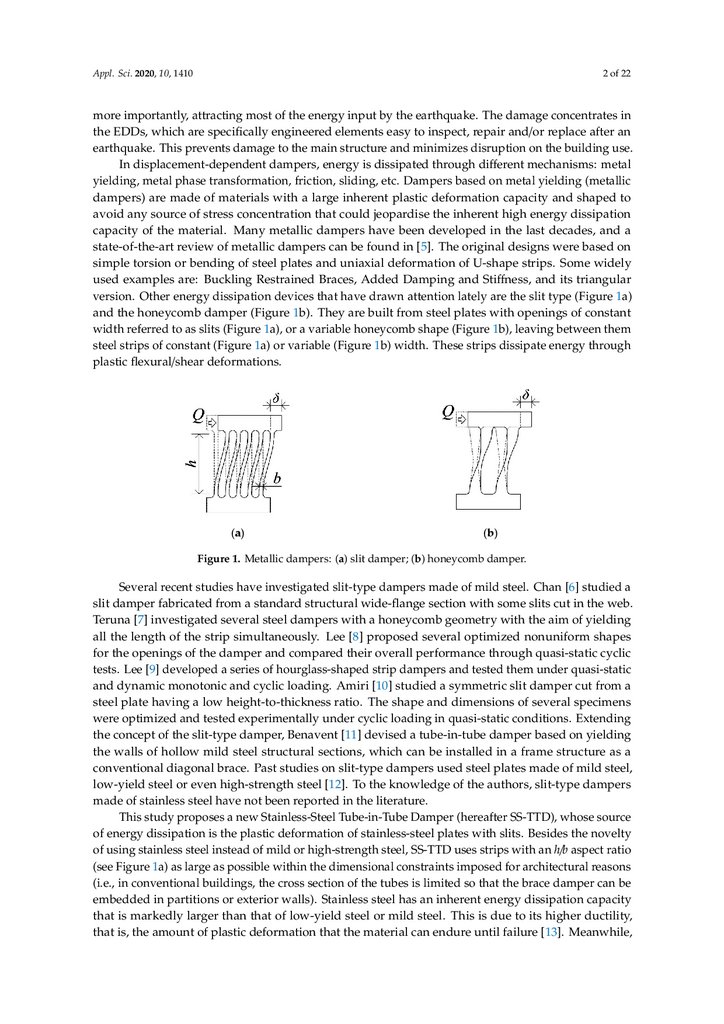
Other energy dissipation devices that have drawn attention lately are the slit type (Figure 1a) and the
and the honeycomb damper (Figure 1b). They are built from steel plates with openings of constant
honeycomb damper (Figure 1b). They are built from steel plates with openings of constant width
width referred to as slits (Figure 1a), or a variable honeycomb shape (Figure 1b), leaving between them
referred to as slits (Figure 1a), or a variable honeycomb shape (Figure 1b), leaving between them steel
steel strips of constant (Figure 1a) or variable (Figure 1b) width. These strips dissipate energy through
strips of constant (Figure 1a) or variable (Figure 1b) width. These strips dissipate energy through
plastic
flexural/shear deformations.
plastic flexural/shear deformations.
(a)
(b)
Figure
Metallicdampers:
dampers:(a)
(a) slit
slit damper;
damper; (b)
Figure
1. 1.
Metallic
(b)honeycomb
honeycombdamper.
damper.
Several
recent
studies
have
investigatedslit-type
slit-typedampers
dampersmade
madeof
ofmild
mild steel.
steel. Chan
Several
recent
studies
have
investigated
Chan [6]
[6]studied
studied a
a
slit
damper
fabricated
from
a
standard
structural
wide-flange
section
with
some
slits
cut
in
thethe
web.
slit damper fabricated from a standard structural wide-flange section with some slits cut in
web.
Teruna
[7]
investigated
several
steel
dampers
with
a
honeycomb
geometry
with
the
aim
of
yielding
Teruna [7] investigated several steel dampers with a honeycomb geometry with the aim of yielding
all the length of the strip simultaneously. Lee [8] proposed several optimized nonuniform shapes for
all the length of the strip simultaneously. Lee [8] proposed several optimized nonuniform shapes
the openings of the damper and compared their overall performance through quasi-static cyclic tests.
for the openings of the damper and compared their overall performance through quasi-static cyclic
Lee [9] developed a series of hourglass-shaped strip dampers and tested them under quasi-static and
tests. Lee [9] developed a series of hourglass-shaped strip dampers and tested them under quasi-static
dynamic monotonic and cyclic loading. Amiri [10] studied a symmetric slit damper cut from a steel
andplate
dynamic
monotonic and cyclic loading. Amiri [10] studied a symmetric slit damper cut from a
having a low height-to-thickness ratio. The shape and dimensions of several specimens were
steel
plate having
a low experimentally
height-to-thickness
shape
and dimensions
of several
specimens
optimized
and tested
underratio.
cyclic The
loading
in quasi-static
conditions.
Extending
the
were
optimized
and
tested
experimentally
under
cyclic
loading
in
quasi-static
conditions.
Extending
concept of the slit-type damper, Benavent [11] devised a tube-in-tube damper based on yielding
the
the walls
concept
the slit-type
damper,
Benavent
[11]which
devised
tube-in-tube
on yielding
of of
hollow
mild steel
structural
sections,
cana be
installed indamper
a framebased
structure
as a
the conventional
walls of hollow
mildbrace.
steel Past
structural
which
can be
installed
in a made
frameofstructure
as a
diagonal
studiessections,
on slit-type
dampers
used
steel plates
mild steel,
conventional
diagonal
brace.
Past studies
slit-type
used
steel
plates slit-type
made ofdampers
mild steel,
low-yield steel
or even
high-strength
steelon
[12].
To thedampers
knowledge
of the
authors,
low-yield
or even
[12].inTothe
the
knowledge of the authors, slit-type dampers
made ofsteel
stainless
steelhigh-strength
have not beensteel
reported
literature.
studysteel
proposes
a new
Stainless-Steel
Tube-in-Tube
made ofThis
stainless
have not
been
reported in the
literature. Damper (hereafter SS-TTD), whose
source
of energy
dissipation
the plastic deformation
of stainless-steel
plates with
slits. whose
Besidessource
the
This study
proposes
a newisStainless-Steel
Tube-in-Tube
Damper (hereafter
SS-TTD),
novelty
of
using
stainless
steel
instead
of
mild
or
high-strength
steel,
SS-TTD
uses
strips
with
an
h/b
of energy dissipation is the plastic deformation of stainless-steel plates with slits. Besides the novelty
aspect
ratio
(see
Figure
1a)
as
large
as
possible
within
the
dimensional
constraints
imposed
for
of using stainless steel instead of mild or high-strength steel, SS-TTD uses strips with an h/b aspect ratio
in conventional
theconstraints
cross section
of the tubes
is limited soreasons
that
(seearchitectural
Figure 1a) asreasons
large as(i.e.,
possible
within the buildings,
dimensional
imposed
for architectural
brace damper can be embedded in partitions or exterior walls). Stainless steel has an inherent
(i.e.,the
in conventional
buildings, the cross section of the tubes is limited so that the brace damper can be
energy dissipation capacity that is markedly larger than that of low-yield steel or mild steel. This is
embedded in partitions or exterior walls). Stainless steel has an inherent energy dissipation capacity
that is markedly larger than that of low-yield steel or mild steel. This is due to its higher ductility,
that is, the amount of plastic deformation that the material can endure until failure [13]. Meanwhile,
3.
Appl. Sci. 2020, 10, 14103 of 22
Appl. Sci. 2020, 10, 1410
3 of 23
dueh/b
to ratios
its higher
ductility,
is, the amount
of plastic
theand
material
can the
endure
large
guarantee
a that
flexural-type
yielding
modedeformation
of the steel that
strips
enhance
energy
until failure
[13]. Meanwhile,
largeThe
h/b ratios
guarantee
a flexural-type
yielding
mode of the
steel
dissipation
capacity
of the damper.
performance
of the
SS-TTD in terms
of hysteretic
behaviour,
strips and
energydissipation
dissipationcapacity
capacityisofinvestigated
the damper. through
The performance
the SS-TTD
ductility
andenhance
ultimatethe
energy
dynamicofshaking
tableintests
terms
of
hysteretic
behaviour,
ductility
and
ultimate
energy
dissipation
capacity
is
investigated
and quasi-static cyclic tests. A comparison with other metallic dampers proposed in the literature
dynamic
shaking
table tests and
quasi-static
cyclic tests.
comparison
other
is through
presented.
Finally,
two numerical
models
are proposed
and A
compared,
to with
predict
themetallic
hysteretic
dampers
proposed
in
the
literature
is
presented.
Finally,
two
numerical
models
are
proposed
and
behaviour and failure of the damper.
compared, to predict the hysteretic behaviour and failure of the damper.
2. Proposed Seismic Damper
2. Proposed Seismic Damper
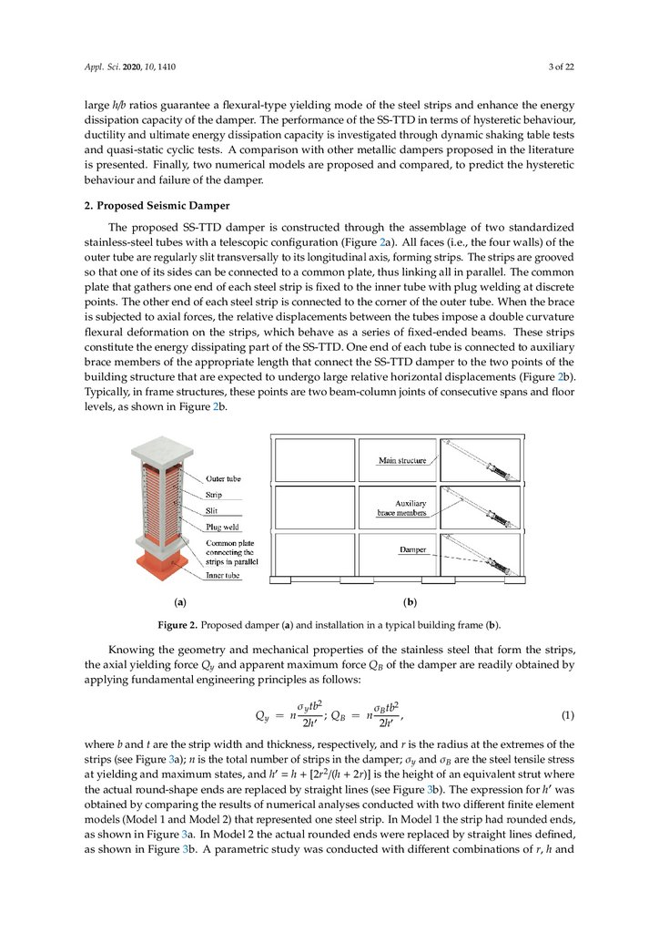
The proposed SS-TTD damper is constructed through the assemblage of two standardized
The proposed SS-TTD damper is constructed through the assemblage of two standardized
stainless-steel tubes with a telescopic configuration (Figure 2a). All faces (i.e., the four walls) of the
stainless-steel tubes with a telescopic configuration (Figure 2a). All faces (i.e., the four walls) of the
outer tube are regularly slit transversally to its longitudinal axis, forming strips. The strips are grooved
outer tube are regularly slit transversally to its longitudinal axis, forming strips. The strips are
so that one of its sides can be connected to a common plate, thus linking all in parallel. The common
grooved so that one of its sides can be connected to a common plate, thus linking all in parallel. The
plate
that gathers
one
end ofone
each
strip
is fixed
the inner
at discrete
common
plate that
gathers
endsteel
of each
steel
strip to
is fixed
to thetube
innerwith
tubeplug
withwelding
plug welding
at
points.
The
other
end
of
each
steel
strip
is
connected
to
the
corner
of
the
outer
tube.
When
the brace
discrete points. The other end of each steel strip is connected to the corner of the outer tube. When
is the
subjected
axial forces,
the forces,
relative
displacements
betweenbetween
the tubes
impose
a double
curvature
brace istosubjected
to axial
the
relative displacements
the
tubes impose
a double
flexural
deformation
on
the
strips,
which
behave
as
a
series
of
fixed-ended
beams.
These
strips
curvature flexural deformation on the strips, which behave as a series of fixed-ended beams. These
constitute
the energy
part of part
the SS-TTD.
One end
ofend
eachoftube
connected
to auxiliary
strips constitute
the dissipating
energy dissipating
of the SS-TTD.
One
eachistube
is connected
to
brace
members
the appropriate
length that
connect
the SS-TTD
damper
to the
points
of the
auxiliary
braceof
members
of the appropriate
length
that connect
the SS-TTD
damper
to two
the two
points
of the building
structure
that
are expected
to undergo
large
relative
horizontal
displacements(Figure
(Figure 2b).
building
structure
that are
expected
to undergo
large
relative
horizontal
displacements
2b).
Typically,
in
frame
structures,
these
points
are
two
beam-column
joints
of
consecutive
spans
andfloor
Typically, in frame structures, these points are two beam-column joints of consecutive spans and
floor as
levels,
as shown
in Figure
levels,
shown
in Figure
2b. 2b.
(a)
(b)
Figure2.2.Proposed
Proposed damper
damper (a)
building
frame
(b).(b).
Figure
(a)and
andinstallation
installationinina typical
a typical
building
frame
Knowingthe
the geometry
geometry and
properties
of the
steel that
strips,
Knowing
andmechanical
mechanical
properties
of stainless
the stainless
steelform
thatthe
form
thethe
strips,
force
QyQand
apparent
maximum
force
Q
B Q
of
the
damper
are
readily
obtained
by
theaxial
axialyielding
yielding
force
and
apparent
maximum
force
of
the
damper
are
readily
obtained
by
y
B
applying
fundamental
engineering
principles
as
follows:
applying fundamental engineering principles as follows: