
 Литература
Похожие презентации:


Electronic Journal «Technical Acoustics»
1.
Electronic Journal «Technical Acoustics»http://webcenter.ru/~eeaa/ejta/
2004, 14
Konstantin I. Matveev
California Institute of Technology, Pasadena, CA, 91125, USA
e-mail: matveev@caltech.edu
Vortex-acoustic instability in chambers with mean flow
and heat release
Received 30.09.2004, published 18.10.2004
Acoustic instability appearing in chambers with isothermal or reacting mean flow is
an important engineering problem. The subject of this work is the instability that is
coupled with vortex shedding and impingement, which can also be accompanied by
heat release. A reduced-order theory is formulated that includes the chamber acoustics,
vortex-structure interaction, and unsteady heat addition. Assuming that acoustic
sources are localized in space and time, the kicked oscillator concept is applied. Model
results are compared with experimental data. Possible applications for flow control are
discussed.
1. INTRODUCTION
Intensive pressure and flow fluctuations in the combustion chambers of rocket motors and
similar unstable phenomena in industrial applications involving ducts with isothermal mean flow
are important problems in mechanical engineering. In the development stage of rocket motors,
practically all of them experience some kind of these instabilities. This effect is very harmful, since
it may lead to intensive vibrations, unacceptable for navigation systems and payload, and to
enhanced heat transfer, which can result in overheating the structure. In extreme cases, rockets are
damaged or destroyed by mechanical or thermal mechanisms related to acoustic-combustion
instability. The problem of the acoustic instability in rocket flows attracted a lot of attention by
researchers, and extensive theoretical, experimental, and numerical studies were undertaken [1–6].
There is a variety of causes for acoustic instability in the systems with mean flow and heat
addition. This paper is concerned only with those that are coupled with vortex shedding occurring
inside the chambers. This type of instability can be approximately subdivided into two groups. In
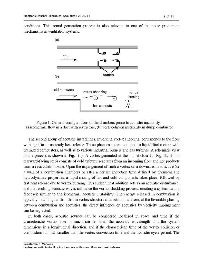
the first one, the vorticity impinging on the structure acts as an acoustic disturbance. A scheme of
such a process is shown in Fig. 1(a). There are baffles in the chamber that are analogous to
restrictors between propellant segments in actual solid-fuel rocket motors. Vortices are generated
on upstream baffles and impinge on downstream restrictors. Acoustic disturbances produced at
the moments of vortex collisions feed back to the process of vortex shedding. A closed-loop
system is formed that can exhibit self-excited oscillations at the suitable geometry and flow
2.
Electronic Journal «Technical Acoustics» 2004, 142 of 15
____________________________________________________________________________________________
conditions. This sound generation process is also relevant to one of the noise production
mechanisms in ventilation systems.
(a)
(b)
baffles
Figure 1. General configurations of the chambers prone to acoustic instability:
(a) isothermal flow in a duct with restrictors; (b) vortex-driven instability in dump combustor
The second group of acoustic instabilities, involving vortex shedding, corresponds to the flow
with significant unsteady heat release. These phenomena are common to liquid-fuel motors with
premixed combustors, as well as to various industrial burners and gas turbines. A schematic view
of the process is shown in Fig. 1(b). A vortex generated at the flameholder (in Fig. 1b, it is a
rearward-facing step) consists of cold unburnt reactants from an incoming flow and hot products
from a recirculation zone. Upon the impingement of such a vortex on a downstream structure (or
a wall of a combustion chamber) or after a certain induction time defined by chemical and
hydrodynamic properties, a rapid mixing of hot and cold components takes place, followed by
fast heat release due to vortex burning. This sudden heat addition acts as an acoustic disturbance,
and the resulting acoustic waves influence the vortex shedding process, creating a system with a
feedback similar to the isothermal acoustic instability. The energy released in combustion is
typically much higher than that in vortex-structure interaction; therefore, at the favorable phasing
between combustion and acoustics, the direct influence on acoustics by vorticity impingement
can be neglected.
In both cases, acoustic sources can be considered localized in space and time if the
characteristic vortex size is much smaller than the acoustic wavelength and the system
dimensions in a longitudinal direction, and if the characteristic time of the vortex collision or
combustion is much smaller than the vortex convection time and the acoustic cycle period. The
____________________________________________________________________________________________
Konstantin I. Matveev
Vortex-acoustic instability in chambers with mean flow and heat release
3.
Electronic Journal «Technical Acoustics» 2004, 143 of 15
____________________________________________________________________________________________
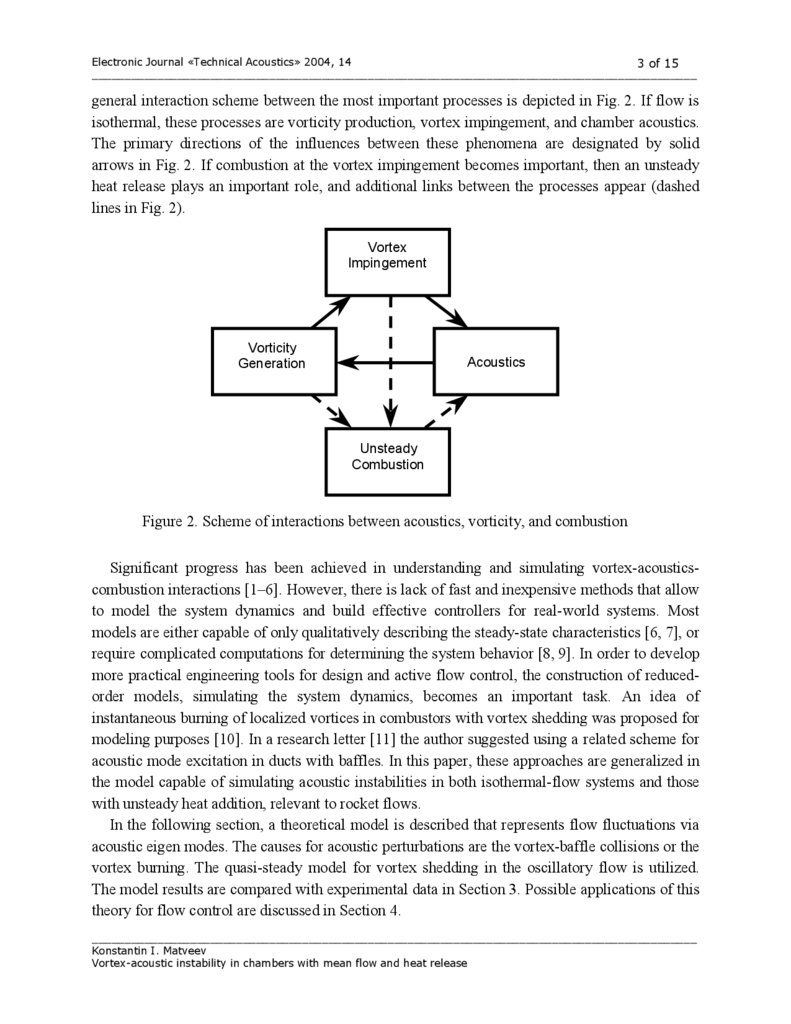
general interaction scheme between the most important processes is depicted in Fig. 2. If flow is
isothermal, these processes are vorticity production, vortex impingement, and chamber acoustics.
The primary directions of the influences between these phenomena are designated by solid
arrows in Fig. 2. If combustion at the vortex impingement becomes important, then an unsteady
heat release plays an important role, and additional links between the processes appear (dashed
lines in Fig. 2).
Vortex
Impingement
Vorticity
Generation
Acoustics
Unsteady
Combustion
Figure 2. Scheme of interactions between acoustics, vorticity, and combustion
Significant progress has been achieved in understanding and simulating vortex-acousticscombustion interactions [1–6]. However, there is lack of fast and inexpensive methods that allow
to model the system dynamics and build effective controllers for real-world systems. Most
models are either capable of only qualitatively describing the steady-state characteristics [6, 7], or
require complicated computations for determining the system behavior [8, 9]. In order to develop
more practical engineering tools for design and active flow control, the construction of reducedorder models, simulating the system dynamics, becomes an important task. An idea of
instantaneous burning of localized vortices in combustors with vortex shedding was proposed for
modeling purposes [10]. In a research letter [11] the author suggested using a related scheme for
acoustic mode excitation in ducts with baffles. In this paper, these approaches are generalized in
the model capable of simulating acoustic instabilities in both isothermal-flow systems and those
with unsteady heat addition, relevant to rocket flows.
In the following section, a theoretical model is described that represents flow fluctuations via
acoustic eigen modes. The causes for acoustic perturbations are the vortex-baffle collisions or the
vortex burning. The quasi-steady model for vortex shedding in the oscillatory flow is utilized.
The model results are compared with experimental data in Section 3. Possible applications of this
theory for flow control are discussed in Section 4.
____________________________________________________________________________________________
Konstantin I. Matveev
Vortex-acoustic instability in chambers with mean flow and heat release
4.
Electronic Journal «Technical Acoustics» 2004, 144 of 15
____________________________________________________________________________________________
2. THEORETICAL MODEL
A duct with a mean flow is considered as a general configuration for analyzing acoustic
instabilities inside real-world chambers. Examples of the parts of the duct, where all major
processes happen, are shown in Fig. 1 for two cases of isothermal flow and flow with heat
addition. Only longitudinal acoustics is the subject of this work, and one-dimensional acoustic
theory is applied to model disturbed motions. Mach numbers of both mean and oscillating flow
components are considered small.
Two locations inside the motor chamber, which are important for the phenomena studied, are
the point of vortex formation and the point of vortex impingement on the structure (or its position
when it burns abruptly). The first location is associated with an upstream baffle (Fig. 1a) or a
rearward-facing step (Fig. 1b). The second location is either the downstream baffle (Fig. 1a) or
the point of vortex burning (Fig. 1b), which depends on chemical and hydrodynamic properties of
the system.
Disturbed motions in the chamber are represented through the acoustic mode expansion in the
following form [12]:
p' ( x, t ) = ∑ p ' n ( x, t ) = p 0 ∑η n (t )ψ n ( x) ,
u ' ( x, t ) = ∑ u ' n ( x , t ) = ∑
1 dη n dψ n ( x )
,
dx
γ k n2 dt
(1)
(2)
where p0 is the mean undisturbed pressure, η n (t ) is the time-varying amplitude of the nth mode,
ψ n (x) is the pressure mode shape, γ is the gas constant, and k n is the modal wave number.
The dynamics of the modal time variables will be determined using a one-dimensional wave
equation with spatially averaged gas properties over a chamber volume and two driving sources
pertinent to the phenomena studied [13]:
2
∂ 2 p'
∂F
∂Q
2 ∂ p'
a
,
−
= − ρa 2
+ ρa 2
2
2
∂x
∂t
∂t
∂x
(3)
where x is the horizontal coordinate (starting from an upstream end of the duct), a is the speed
of sound, ρ is the gas density, F is the force per unit of mass, and Q is the heat addition rate
per unit of volume.
The driving sources on the right-hand side of Eq. (2) model the acoustic disturbances
happening at the moments of vortex impingement (or burning). The force F represents the
dipole source, which is the most effective radiator caused by vorticity impingement. The
unsteady heat release rate Q is the dominant source in reacting flows.
Equations for mode dynamics can be obtained by substituting Eqs. (1) and (2) into Eq. (3),
multiplying it by the mode shape, and integrating over a chamber length. Neglecting by the mode
non-orthogonality and introducing a modal damping ξ , dynamics equations for individual modes
are derived:
____________________________________________________________________________________________
Konstantin I. Matveev
Vortex-acoustic instability in chambers with mean flow and heat release
5.
Electronic Journal «Technical Acoustics» 2004, 145 of 15
____________________________________________________________________________________________
d 2η n
dη n
γ
∂F ∂Q
+ 2ξ n ω n
+ ω n2η n = 2 ∫ψ n −
+
dx ,
2
dt
dt
En
∂x ∂t
(4)
where E n2 = ∫ψ n2 dx .
To model the force F and the heat addition Q , the assumption of a shortness of the
impingement and burning, as well as the localized character of these acoustic sources, will be
used. Also, the magnitude of these disturbances should grow with increasing vortex circulation
Γ , which correlates with a vortex size. Thus, the force and heat release can be approximated by
the following expressions, involving delta functions in space and time:
F = c F ∑ Γ j δ ( L − x j )δ (t − t j ) ,
(5)
Q = cQ ∑ Γ j δ ( L − x j )δ (t − t j ) ,
(6)
j
j
where summation is carried on the number of vortices shed, L is the location of the vortex
impingement (burning) point in the chamber, x j is the position of the jth vortex, and t j is the
moment of impingement (burning) of the jth vortex. Numerical values for coefficients c F and cQ
can be determined using theoretical, numerical or experimental results for particular situations. In
this study, we will determine them empirically by fitting model results to experimental data. The
vortex instantaneous velocity is approximated by the formula
dx j
dt
= α u0 ( x j ) + u' ( x j , t ) ,
(7)
where u0 is the mean flow velocity at the plane of the vortex formation (at the upstream baffle or
at the step in a combustor).
The coefficient α accounts for a reduced velocity of the vortex convection due its motion
along the boundary of the recirculation zone. For example, this coefficient is commonly in the
range 0.5–0.6 for the solid-fuel rocket motors with cavities between propellant segments [6].
Substituting Eqs. (5–6) into Eq. (4) and integrating over a chamber length, we find the
dynamics equation for the nth mode amplitude in time interval (t j −1 ; t j +1 ) :
d 2η n
dη n
dψ n
dδ
(t − t j ) + c Fn
( x 2 )Γ j δ (t − t j ) ,
+ 2ξ n ω n
+ ω n2η n = cQnψ n ( x 2 )Γ j
2
dt
dt
dx
dt
(8)
where cQn = cQγ / En2 and c Fn = c F γ / En2 .
Differential equations with forces containing delta functions in time describe dynamics of the
systems that belong to the family of kicked oscillators [14]. The system behaves as an ordinary
linear oscillator almost all the time except time moments t j , where jumps in variables occur. The
____________________________________________________________________________________________
Konstantin I. Matveev
Vortex-acoustic instability in chambers with mean flow and heat release
6.
Electronic Journal «Technical Acoustics» 2004, 146 of 15
____________________________________________________________________________________________
influence of delta function is analogous to the instantaneous increment in the variable velocity
[15], while a time derivative of the delta function modifies the variable itself [10]. If the modal
damping is small enough, then the following jump conditions are satisfied at time t j :
η n (t j + ) − η n (t j − ) = cQnψ n ( x2 )Γ j ,
dη n
dη
dψ n
(t j + ) − n (t j − ) = c Fn
( x 2 )Γ j .
dt
dt
dx
(9)
(10)
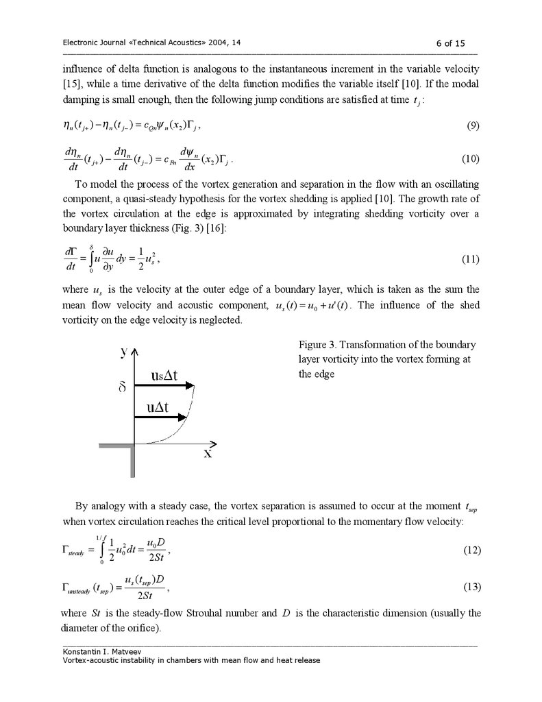
To model the process of the vortex generation and separation in the flow with an oscillating
component, a quasi-steady hypothesis for the vortex shedding is applied [10]. The growth rate of
the vortex circulation at the edge is approximated by integrating shedding vorticity over a
boundary layer thickness (Fig. 3) [16]:
δ
∂u
dΓ
1
= ∫ u dy = u s2 ,
dt 0 ∂y
2
(11)
where u s is the velocity at the outer edge of a boundary layer, which is taken as the sum the
mean flow velocity and acoustic component, u s (t ) = u 0 + u ' (t ) . The influence of the shed
vorticity on the edge velocity is neglected.
Figure 3. Transformation of the boundary
layer vorticity into the vortex forming at
the edge
By analogy with a steady case, the vortex separation is assumed to occur at the moment t sep
when vortex circulation reaches the critical level proportional to the momentary flow velocity:
1/ f
Γsteady =
∫
0
u D
1 2
u 0 dt = 0 ,
2
2St
Γunsteady (t sep ) =
u s (t sep ) D
2 St
,
(12)
(13)
where St is the steady-flow Strouhal number and D is the characteristic dimension (usually the
diameter of the orifice).
____________________________________________________________________________________________
Konstantin I. Matveev
Vortex-acoustic instability in chambers with mean flow and heat release
7.
Electronic Journal «Technical Acoustics» 2004, 147 of 15
____________________________________________________________________________________________
The quasi-steady vortex shedding hypothesis was verified against experimental data [10, 17].
However, this hypothesis is not universally held in all possible cases of the vortex shedding in
unsteady flow, and a caution is needed to apply it for particular cases. To simplify the modeling,
another assumption is imposed on the vortex dynamics: its circulation remains constant between
the moments of the vortex detachment and impingement.
The formulation of the vortex dynamics sub-model completes the mathematical theory for
acoustic instability in chambers involving vortex shedding. The system behavior can now be
studied by integrating numerically the dynamics equations for the modes and vortices.
3. EXPERIMENTAL AND MODEL RESULTS
The theory outlined in the previous section contains some non-obvious assumptions, such as
spatially and timely localized acoustic sources caused by vortex impingement and burning. To
prove that the model has meaning and can be used in practice, a verification of the model results
against test data is necessary. For a valid prediction, the accurate identification of the system
geometry, hydrodynamics, acoustics, and combustion is required. In this section, three welldefined experimental situations, two dealing with isothermal flow and one with reacting flow, are
modeled.
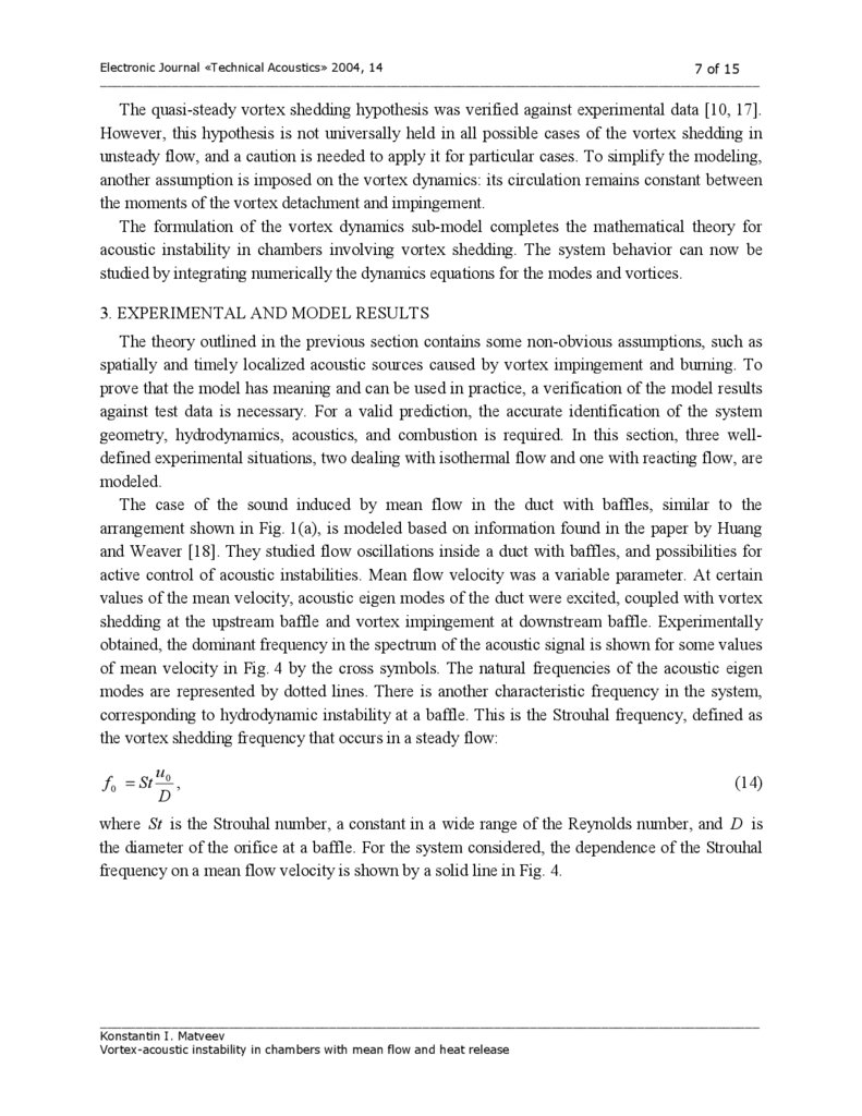
The case of the sound induced by mean flow in the duct with baffles, similar to the
arrangement shown in Fig. 1(a), is modeled based on information found in the paper by Huang
and Weaver [18]. They studied flow oscillations inside a duct with baffles, and possibilities for
active control of acoustic instabilities. Mean flow velocity was a variable parameter. At certain
values of the mean velocity, acoustic eigen modes of the duct were excited, coupled with vortex
shedding at the upstream baffle and vortex impingement at downstream baffle. Experimentally
obtained, the dominant frequency in the spectrum of the acoustic signal is shown for some values
of mean velocity in Fig. 4 by the cross symbols. The natural frequencies of the acoustic eigen
modes are represented by dotted lines. There is another characteristic frequency in the system,
corresponding to hydrodynamic instability at a baffle. This is the Strouhal frequency, defined as
the vortex shedding frequency that occurs in a steady flow:
f 0 = St
u0
,
D
(14)
where St is the Strouhal number, a constant in a wide range of the Reynolds number, and D is
the diameter of the orifice at a baffle. For the system considered, the dependence of the Strouhal
frequency on a mean flow velocity is shown by a solid line in Fig. 4.
____________________________________________________________________________________________
Konstantin I. Matveev
Vortex-acoustic instability in chambers with mean flow and heat release
8.
Electronic Journal «Technical Acoustics» 2004, 148 of 15
____________________________________________________________________________________________
450
Dom inant frequency [Hz]
400
350
300
250
200
150
100
50
0
10
15
20
25
30
Mean flow velocity [m/s]
Figure 4. Dominant frequency of the sound produced in isothermal flow through the duct with
baffles: o — model results, x — test data [18]. Dotted lines — natural frequencies of acoustic
modes; solid line — mean-flow Strouhal frequency
At the resonances observed, there was the identifiable integer number of vortices convected
between the baffles. In the regions close to intersections of the Strouhal frequency line with
acoustic eigen mode frequencies, there was only one vortex. At the mean velocities of about 10
and 12 m/s, there were two and three vortices between the baffles. The attraction of the dominant
frequency to the natural frequencies of the system and weak variation of the sound frequency
with a mean velocity in these regions is known as the lock-in phenomenon, which is often
observed in self-oscillating systems.
The model for simulating this experiment has the parameters identical to those of the actual
test system. The first natural frequency is 57 Hz. Higher frequencies are multiple integers of the
first one. The six lowest modes are accounted for in the mathematical modeling. The duct is
open-ended. The Strouhal number is 0.87. The coefficient α (Eq. 7) for the reduced convection
velocity is 0.6. Damping coefficients are calculated from the standard expressions for sound
attenuation due to a boundary layer and sound radiation from the open ends [13]. The forcing
coefficient cFn is empirically chosen for all modes to be equal 0.1 m-1. More accurate
identification of this coefficient would require computational fluid dynamics studies of the vortex
impingement process. Since the flow is non-reacting, the other forcing coefficient, cQn , is zero.
Numerical results are obtained by integrating dynamics equations given in Section 2. At the
initial time moment, there are no flow disturbances. Due to hydrodynamic instability at the
____________________________________________________________________________________________
Konstantin I. Matveev
Vortex-acoustic instability in chambers with mean flow and heat release
9.
Electronic Journal «Technical Acoustics» 2004, 149 of 15
____________________________________________________________________________________________
upstream baffle, vortices are generated, and their impingement on the downstream baffle leads to
excitation of the acoustic eigen modes of the duct. Integration is carried out until the system
reaches a steady state with well-defined periodic behavior of the system variables.
Numerical results for the dominant frequency in the acoustic signal at resonances are shown in
Fig. 4 by the open circle symbols. The model results generally agree with the test data, predicting
correctly the lock-in regions. Even the excitation of higher modes at low Strouhal frequency (in
the mean velocity range of 10–13 m/s) is captured well by the modeling. One of the possible
reasons for the excitation of higher modes, in particularly the third mode in this case, is the
remoteness of the mean-flow Strouhal frequency from the closest natural frequencies, while the
Strouhal frequency becomes a subharmonic of a higher mode. A fair agreement between model
results and test data demonstrates that the theory developed can be used for practical design and
control of the sound-vortex interaction in isothermal systems.
Let us now consider a system with heat release, similar to that shown in Fig. 1(b).
Experiments on a dump combustor built at California Institute of Technology were described by
Smith [19]. For certain values of the mean flow velocity and the fuel-to-oxidizer ratio, acoustic
modes of the system were excited and accompanied by regular vortex shedding and cyclic heat
release rate with periods of acoustic oscillations. Heat release had articulate maximums correlated
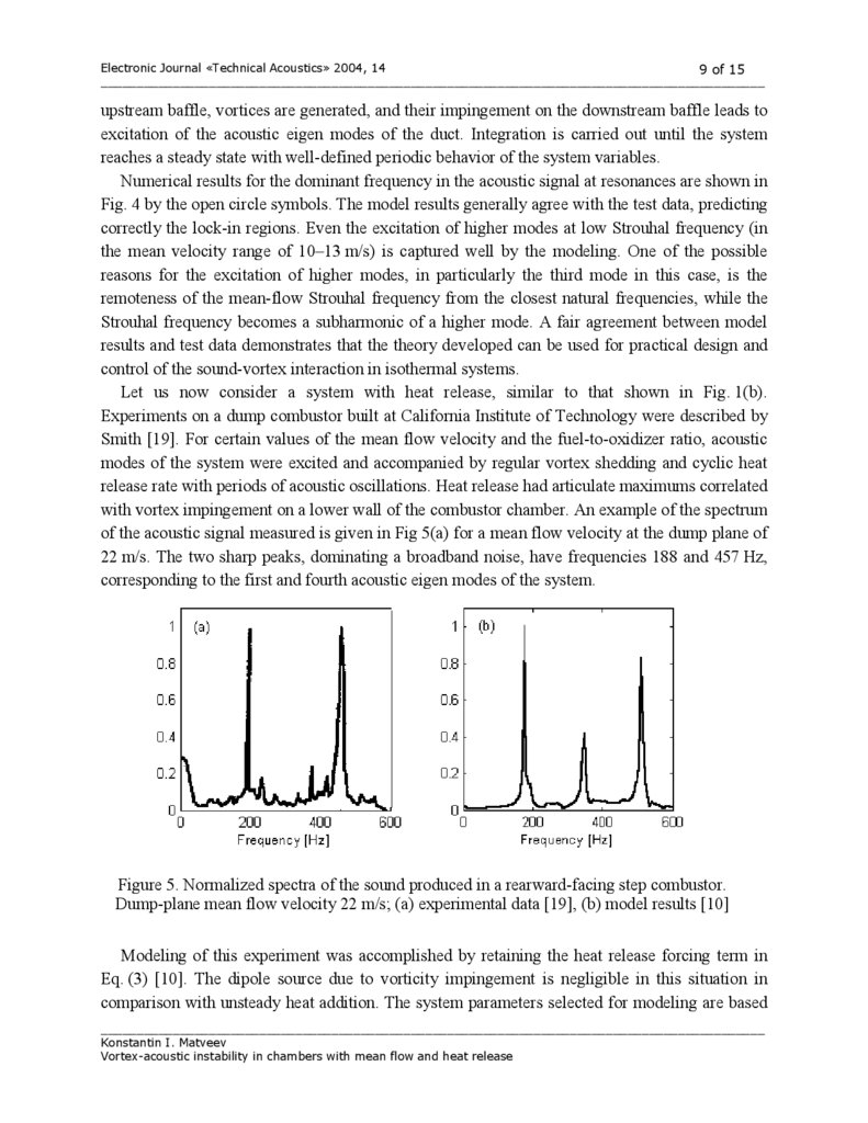
with vortex impingement on a lower wall of the combustor chamber. An example of the spectrum
of the acoustic signal measured is given in Fig 5(a) for a mean flow velocity at the dump plane of
22 m/s. The two sharp peaks, dominating a broadband noise, have frequencies 188 and 457 Hz,
corresponding to the first and fourth acoustic eigen modes of the system.
Figure 5. Normalized spectra of the sound produced in a rearward-facing step combustor.
Dump-plane mean flow velocity 22 m/s; (a) experimental data [19], (b) model results [10]
Modeling of this experiment was accomplished by retaining the heat release forcing term in
Eq. (3) [10]. The dipole source due to vorticity impingement is negligible in this situation in
comparison with unsteady heat addition. The system parameters selected for modeling are based
____________________________________________________________________________________________
Konstantin I. Matveev
Vortex-acoustic instability in chambers with mean flow and heat release
10.
Electronic Journal «Technical Acoustics» 2004, 1410 of 15
____________________________________________________________________________________________
on information available for the combustor studied [19, 20]. The model results in a form of the
acoustic spectrum at the given mean velocity are shown in Fig. 5(b). The two dominant
components have frequencies 177 and 513 Hz. There is also another noticeable peak, although
with a smaller magnitude. The approximate agreement between experimental data and model
results, as seen in Fig. 5, manifests the relevance of the model to real combustors. This allows
using the theory developed here for preliminary design and analysis of combustion systems prone
to acoustic instability coupled with vortex shedding. The discrepancy between model and test
data is due to an attempt to describe a very complicated real process with a fairly simple model.
Further model developing (and complicating) may improve its accuracy with regard to unstable
combustion devices.
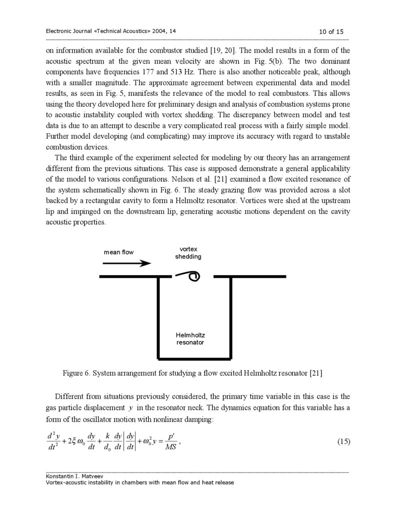
The third example of the experiment selected for modeling by our theory has an arrangement
different from the previous situations. This case is supposed demonstrate a general applicability
of the model to various configurations. Nelson et al. [21] examined a flow excited resonance of
the system schematically shown in Fig. 6. The steady grazing flow was provided across a slot
backed by a rectangular cavity to form a Helmoltz resonator. Vortices were shed at the upstream
lip and impinged on the downstream lip, generating acoustic motions dependent on the cavity
acoustic properties.
mean flow
vortex
shedding
Helmholtz
resonator
Figure 6. System arrangement for studying a flow excited Helmholtz resonator [21]
Different from situations previously considered, the primary time variable in this case is the
gas particle displacement y in the resonator neck. The dynamics equation for this variable has a
form of the oscillator motion with nonlinear damping:
d2y
dy k dy dy
p'
,
+ 2ξ ω 0
+
+ ω 02 y =
2
dt d 0 dt dt
MS
dt
(15)
____________________________________________________________________________________________
Konstantin I. Matveev
Vortex-acoustic instability in chambers with mean flow and heat release
11.
Electronic Journal «Technical Acoustics» 2004, 1411 of 15
____________________________________________________________________________________________
where y coordinate is directed downwards, ξ and k are linear and nonlinear damping
coefficients, d 0 is the slot width, ω 0 is the natural frequency of the Helmholtz resonator, p' is
the driving pressure outside the resonator, M is the inertance of the mass of air in the resonator
neck, and S is the area of the neck.
Nonlinear damping term is important at the resonance condition, when particle velocity
becomes large. From the system description available [21], it follows that the natural frequency is
605 Hz, the slot width is 0.01 m, the linear damping coefficient is 0.049, the inertance of air in
the neck is 22 kg/m4, the neck area is 10-3 m2, and the vortex convection coefficient α (Eq. 7)
is 0.27.
The vortex shedding frequency, corresponding to the mean flow velocity, was empirically
found as the linear function of the velocity far from resonance:
f 0 = St
u0
+∆ f ,
d
(16)
where Strouhal number St is 0.12 and the frequency shift ∆ f is 335 Hz.
It was also found that acoustic particle velocity at the neck was much smaller than the mean
flow velocity, so the circulation growth (Eq. 11) and a moment of the vortex detachment (Eq. 13)
were influenced mostly by mean flow.
The driving pressure term on the right-hand side of Eq. 15 was chosen in the form analogous
to Eqs. (5, 6):
p' = c P ∑ Γ j δ (d − x j )δ (t − t j ) ,
j
(17)
where c P is the appropriate constant, the x coordinate is directed from the upstream to
downstream lip of the resonator neck, the upstream lip being the origin of the x axis; and the
other parameters are the same as in Eqs. (5, 6).
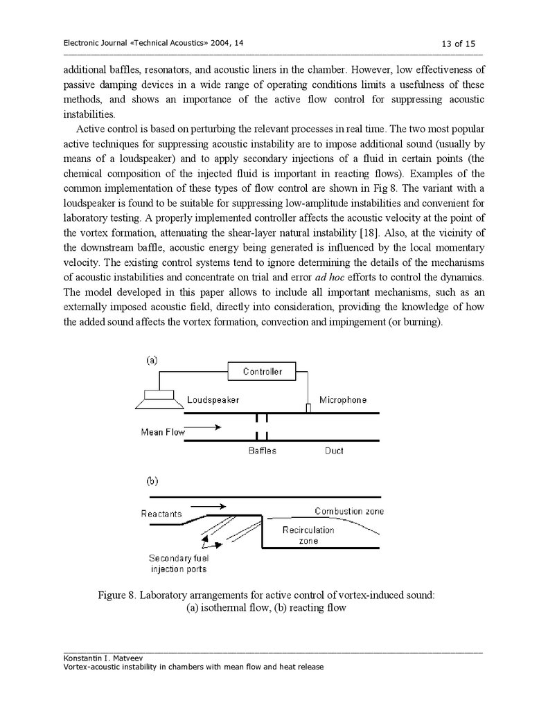
Numerical values for two parameters, c P and k , were selected empirically to be equal to
1.3 kg/m2 and 1.5, respectively. Experimental data and computed results, corresponding to
excited steady states, are shown in Fig. 7 for the sound pressure level inside the cavity and for the
dominant frequency. The results are given versus a variable parameter − the mean flow velocity
outside the resonator. The agreement between test data and model results is good, except for the
magnitude of pressure fluctuations at mean flow velocities much smaller that that corresponding
to a resonance. This comparison demonstrates the relevance of the model even to the systems
different from those upon which the theory was derived (Fig. 1). Other researchers have modeled
the same experiment [21] using other approaches: the describing-function theory [22] and the
computational fluid dynamics method based of the kinetic (Boltzmann) equation [23]. Our simple
model produces results no worse than those obtained by more complicated methods.
____________________________________________________________________________________________
Konstantin I. Matveev
Vortex-acoustic instability in chambers with mean flow and heat release
12.
Frequenc y [Hz]Electronic Journal «Technical Acoustics» 2004, 14
12 of 15
____________________________________________________________________________________________
650
(a)
600
550
500
16
18
20
22
V elocity [m /s]
24
26
28
18
20
22
V elocity [m /s]
24
26
28
140
(b)
S P L [dB ]
135
130
125
120
16
Figure 7. Dominant frequency (a) and sound pressure level (b) of the pressure fluctuations
inside the resonator: o — model results, x — test data [21]
4. POTENTIAL APPLICATION FOR FLOW CONTROL
Acoustic instability in real-world devices is usually a harmful phenomenon that needs to be
suppressed. Both passive and active control methodologies are used in practice. Since the
interactions among vorticity dynamics, acoustics, and combustion are complex, the control of
acoustic instabilities poses a challenging task. An introduction of the reduced-order model
considered in this paper improves the understanding of the relevant process, and makes it
possible to optimize the design and to apply methods of the control theory for a well-defined
system.
Passive control for suppressing acoustic instabilities is usually based on the system geometry
modification. The objectives are to make the processes generating sound fade and to enhance the
acoustic damping. In the general configurations considered here, the first objective is achieved by
selecting the proper horizontal locations for the upstream baffle (or a step in dump combustors)
and the downstream baffle (or a point of vortex burning), as well as the shapes of these system
components. Due to lack of reduced-order models for the sound-producing mechanisms, passive
control methods are usually implemented on a costly trial-and-error approach. The model
proposed in this work allows incorporating explicitly the influence of the system geometry on the
processes of vortex formation and impingement and their interaction with acoustic modes. The
other objective of the passive control, an increase of sound attenuation, is achieved by placing
____________________________________________________________________________________________
Konstantin I. Matveev
Vortex-acoustic instability in chambers with mean flow and heat release
13.
Electronic Journal «Technical Acoustics» 2004, 1413 of 15
____________________________________________________________________________________________
additional baffles, resonators, and acoustic liners in the chamber. However, low effectiveness of
passive damping devices in a wide range of operating conditions limits a usefulness of these
methods, and shows an importance of the active flow control for suppressing acoustic
instabilities.
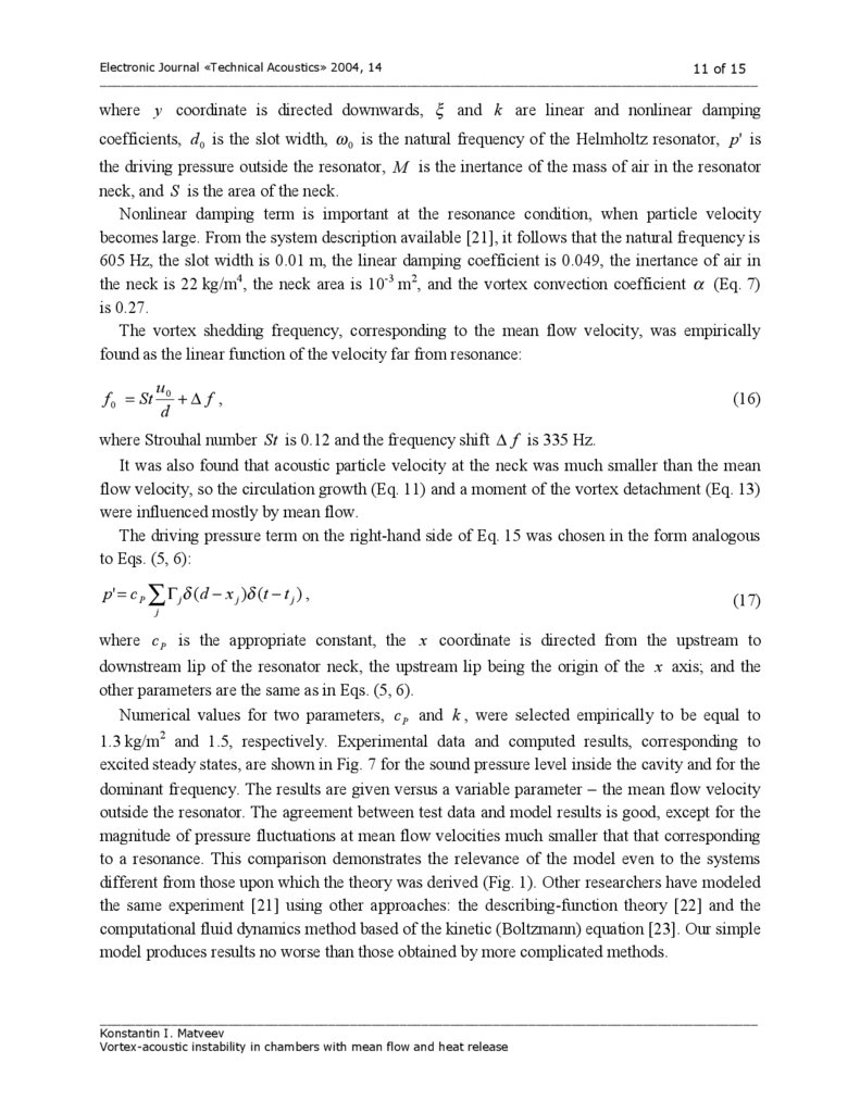
Active control is based on perturbing the relevant processes in real time. The two most popular
active techniques for suppressing acoustic instability are to impose additional sound (usually by
means of a loudspeaker) and to apply secondary injections of a fluid in certain points (the
chemical composition of the injected fluid is important in reacting flows). Examples of the
common implementation of these types of flow control are shown in Fig 8. The variant with a
loudspeaker is found to be suitable for suppressing low-amplitude instabilities and convenient for
laboratory testing. A properly implemented controller affects the acoustic velocity at the point of
the vortex formation, attenuating the shear-layer natural instability [18]. Also, at the vicinity of
the downstream baffle, acoustic energy being generated is influenced by the local momentary
velocity. The existing control systems tend to ignore determining the details of the mechanisms
of acoustic instabilities and concentrate on trial and error ad hoc efforts to control the dynamics.
The model developed in this paper allows to include all important mechanisms, such as an
externally imposed acoustic field, directly into consideration, providing the knowledge of how
the added sound affects the vortex formation, convection and impingement (or burning).
Figure 8. Laboratory arrangements for active control of vortex-induced sound:
(a) isothermal flow, (b) reacting flow
____________________________________________________________________________________________
Konstantin I. Matveev
Vortex-acoustic instability in chambers with mean flow and heat release
14.
Electronic Journal «Technical Acoustics» 2004, 1414 of 15
____________________________________________________________________________________________
In the case of acoustic-vortex-combustion instabilities, more effective and practical way to
suppress instability is to vary the fuel-oxidizer ratio of the fluid injected into combustion
chambers and to utilize secondary injection ports. Variation of the equivalence ratio can be
accounted in the model by changing the magnitude of the heat addition term. Fluid injected into
the flow (Fig. 8b) affects both the process of the vortex formation and the amount of heat to be
released at the vortex burning.
Combustion systems are often characterized by the hysteretic boundary between stable and
unstable operating regimes, i.e. the system state is determined by the history of parameter
variation. Pulses of the fuel at the flame-holding step can initiate a fast transition from the
unstable to stable condition, with other system parameters kept fixed [24]. This is an example of
nonlinear control that may cost less than other control methods, since only a few pulses are
needed for the transition, instead of a continuing action of common controllers. The properties of
this control approach, dealing with complex underlying physical processes, can be studied in a
simple manner using the model developed in this paper.
5. CONCLUSIONS
Acoustic instabilities in ducts, especially those coupled with heat release in combustion
chambers, pose a serious technical problem. Understanding and description of these phenomena
for the systems with vortex shedding is provided in this work on a base of the reduced-order
approach. Model results satisfactorily agree with experimental data in both isothermal and
reacting flows. For successful application of the theory, the system acoustics and hydrodynamics,
as well as the chemistry when combustion is involved, must be known with high accuracy. The
necessary condition for using this model is the compact and time-localized character of acoustic
sources, caused by vortex impingement on the structure or vortex burning.
To make the model developed here be usable in routine engineering practice, the well-defined
quantified criteria for limitations of the model applicability still have to be formulated. To widen
a range of the systems modeled by the theory, the assumptions on time and space compactness of
acoustic sources can be relaxed. However, the challenge will be to stay within a reduced-order
approach. The explicit description of all relevant processes suggests a straightforward application
of the model for flow control. Both passive and active control means can be directly incorporated
into mathematical formulation.
REFERENCES
1. Raushenbakh, B. V. Vibratory Combustion. Fizmatgiz, Moscow, 1961.
2. Harrje, D. T., Reardon, F. H. Liquid propellant rocket combustion instability. NASA SP-194,
1972.
3. Natanzon, M. S. Combustion Instability. Mashinostroenie, Moscow, 1986.
4. Flandro, G. A. Vortex driving mechanism in oscillatory rocket flows. J. Propulsion and
Power, 1986, 2, 206–214.
____________________________________________________________________________________________
Konstantin I. Matveev
Vortex-acoustic instability in chambers with mean flow and heat release
15.
Electronic Journal «Technical Acoustics» 2004, 1415 of 15
____________________________________________________________________________________________
5. Culick, F. E. C. Combustion instabilities in liquid-fuelled propulsion systems – an overview.
AGARD-CP-450, 1988.
6. Dotson, K. W., Koshigoe, S., Pace, K. K. Vortex shedding in a large solid rocket motor
without inhibitors at the segment interfaces. J. Propulsion and Power, 1997, 13, 197–206.
7. Rossiter, J. E. Wind tunnel experiments on the flow over rectangular cavities at subsonic and
transonic speeds. Aeronautical Research Council, Report and Memorandum, No. 3438, 1964.
8. Bruggeman, J. C., Hirschberg, A., van Dongen, M. E. H., Wijnands, A. P. J., Gorter, J. Flow
induced pulsations in gas transport systems: analysis of the influence of closed side branches.
J. Fluids Eng., 1989, 111, 484–491.
9. Hourigan, K., Welsh, M. C., Thompson, M. C., and Stokes, A. N. Aerodynamic sources of
acoustic resonance in a duct with baffles. J. Fluids and Structures, 1990, 4, 345–370.
10. Matveev, K. I., and Culick, F. E. C. A model for combustion instability involving vortex
shedding. Combust. Sci. and Tech., 2003, 175, 1059–1083.
11. Matveev, K. I. Reduced-order modeling of vortex-driven excitation of acoustic modes.
Acoust. Res. Let. Online. In press.
12. Culick, F. E. C. Nonlinear behavior of acoustic waves in combustion chambers. Acta
Astronautica, 1976, 3, 714–757.
13. Howe, M. S. Acoustics of Fluid-Structure Interactions. Cambridge University Press,
Cambridge, 1998.
14. Andronov, A. A., Vitt, A. A., and Khaikin, S. E. Theory of Oscillators. Dover Publications,
New York, 1987.
15. Landau, L. D., Lifshitz, E. M. Mechanics. Pergamon Press, Oxford, 1996.
16. Clements, R. R. An inviscid model of two-dimensional vortex shedding. J. Fluid Mech.,
1973, 57, 321–336.
17. Castro, J. P. Vortex shedding from a ring in oscillatory flow. J. Wind Eng. Ind. Aerodyn.,
1997, 71, 387–398.
18. Huang, X. Y., Weaver, D. S. On the active control of shear layer oscillations across a cavity
in the presence of pipeline acoustic resonance. J. Fluids Struct., 1991, 5, 207–219.
19. Smith, D. A. An Experimental Study of Acoustically Excited, Vortex Driven, Combustion
Instability within a Rearward Facing Step Combustor. Ph. D. dissertation, Caltech, Pasadena,
CA, 1985.
20. Sterling, J. D., Zukoski, E. E. Nonlinear dynamics of laboratory combustor pressure
oscillations. Combust. Sci. and Tech., 1991, 77, 225–238.
21. Nelson, P. A., Halliwell, N. A., and Doak, P. E. Fluid dynamics of a flow excited resonance,
Part I: experiment. J. Sound Vibr., 1981, 78, 15–38.
22. Mast, T. D., Pierce, A. D. Describing-function theory for flow excitation of resonators.
J. Acoust. Soc. Am., 1995, 97(1), 163–172.
23. Mallick, S., Shock, R., Yakhot, V. Numerical simulation of the excitation of a Helmholtz
resonator by a grazing flow. J. Acoust. Soc. Am., 2003, 114(4), 1833–1840.
24. Knoop, P., Culick, F. E. C., Zukoski, E. E. Extension of the stability of motions in a
combustion chamber by nonlinear active control based on hysteresis. Combust. Sci. and
Tech., 1997, 123, 363–376.
____________________________________________________________________________________________
Konstantin I. Matveev
Vortex-acoustic instability in chambers with mean flow and heat release