


 Информатика
 Программное обеспечение
Похожие презентации:
")
")
")
")
")
")
")


Модель вариантов использования в Rose. (Тема 4)
1.
Тема 4: Модель вариантов использования2. Where Are We?
The why and what of a use-case modelElements of a use-case diagram
Flow of events and project artifacts
Elements of an activity diagram
Fundamentals of Rational Rose
Copyright © 2000, 2002 Rational Software, all rights reserved
2
3. Why Create a Use-Case Model?
A use-case model allows the customer andsystem developer to communicate WHAT
the system should do, in a language
understandable to the customer.
Consider the use-case model as the visual
contract between customer and developer.
Fundamentals of Rational Rose
Copyright © 2000, 2002 Rational Software, all rights reserved
3
4.
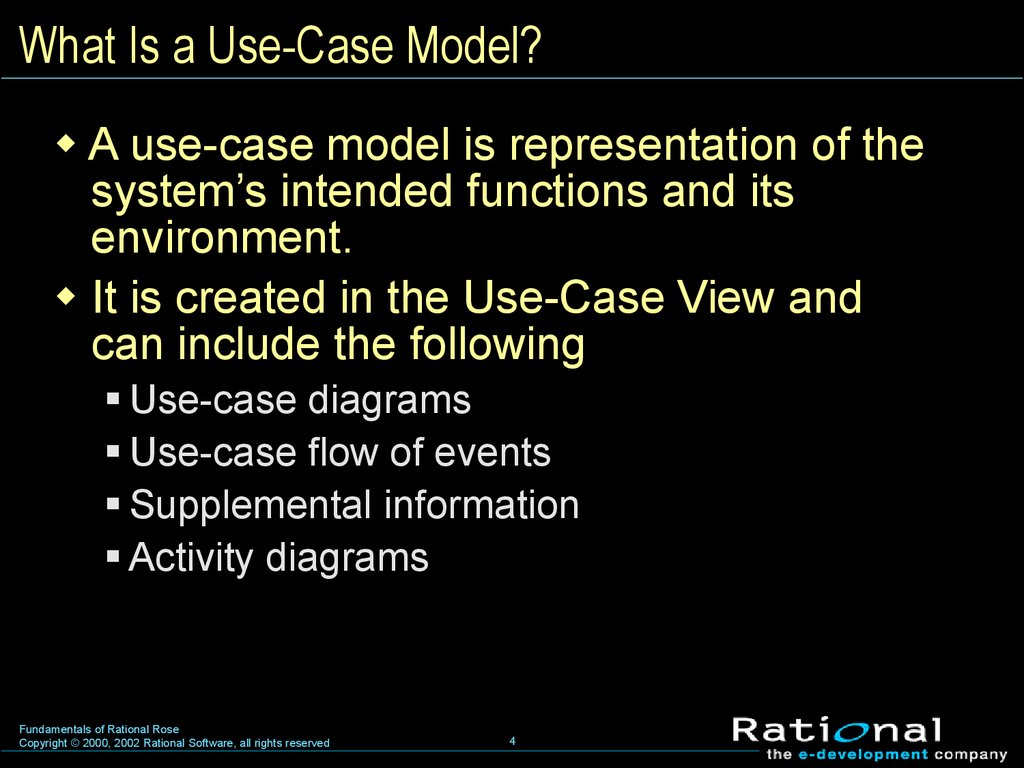
What Is a Use-Case Model?A use-case model is representation of the
system’s intended functions and its
environment.
It is created in the Use-Case View and
can include the following
Use-case diagrams
Use-case flow of events
Supplemental information
Activity diagrams
Fundamentals of Rational Rose
Copyright © 2000, 2002 Rational Software, all rights reserved
4
5. Where Are We?
The why and what of a use-case modelElements of a use-case diagram
Flow of events and project artifacts
Elements of an activity diagram
Fundamentals of Rational Rose
Copyright © 2000, 2002 Rational Software, all rights reserved
5
6. What Is a Use-Case Diagram?
A use-case diagram is an illustration thatshows the relationships among use cases
and actors and among related use cases.
Fundamentals of Rational Rose
Copyright © 2000, 2002 Rational Software, all rights reserved
6
7. What Is a Use-Case Diagram?
A use-case diagram can be modeled in anumber of ways.
(from List Property)
(from Maintain Profile)
Fundamentals of Rational Rose
Copyright © 2000, 2002 Rational Software, all rights reserved
7
8.
Use CasesA use case is a sequence of actions
performed by the system that yields a
measurable value for an actor.
In the UML, a use case is represented
by an oval.
Use Case
Fundamentals of Rational Rose
Copyright © 2000, 2002 Rational Software, all rights reserved
8
9.
ActorsAn actor is someone or something outside
the system that interacts with the system.
In the UML, an actor is represented by a
“stickman.”
Actor
Fundamentals of Rational Rose
Copyright © 2000, 2002 Rational Software, all rights reserved
9
10.
RelationshipsA relationship illustrates a semantic
connection among model elements.
In the UML, an association relationship is
represented by a solid line with or without
an arrow.
Association Relationships
Fundamentals of Rational Rose
Copyright © 2000, 2002 Rational Software, all rights reserved
10
11. Review
1. Why create a use-case model?2. What are possible sources for developing
a use-case diagram?
3. What are the elements of a use-case
diagram?
4. Define a use case.
Fundamentals of Rational Rose
Copyright © 2000, 2002 Rational Software, all rights reserved
11
12. Where Are We?
The why and what of a use-case modelElements of a use-case diagram
Flow of events and project artifacts
Elements of an activity diagram
Fundamentals of Rational Rose
Copyright © 2000, 2002 Rational Software, all rights reserved
12
13. What Is a Flow of Events?
A flow of events is a text description ofthe use case and is part of the use-case
specification.
In Rose, you include each use case’s flow
of events in the Use-Case View.
A flow of events is included under its usecase package in Rose and can be
accessed directly from Rose once it’s
attached.
Fundamentals of Rational Rose
Copyright © 2000, 2002 Rational Software, all rights reserved
13
14. What Are Artifacts?
Artifacts are documents, models, or modelelements used to capture and convey
project information.
In Rose, you will attach only those
artifacts important to maintaining the
use-case model.
Fundamentals of Rational Rose
Copyright © 2000, 2002 Rational Software, all rights reserved
14
15. Where Are We?
The why and what of a use-case modelElements of a use-case diagram
Flow of events and project artifacts
Elements of an activity diagram
Fundamentals of Rational Rose
Copyright © 2000, 2002 Rational Software, all rights reserved
15
16. What Is an Activity Diagram?
An activity diagram in the use-case model can beused to capture the activities in a use case.
It is essentially a flow chart, showing flow of
control from activity to activity.
Flow of Events
This use case starts when the Registrar requests
that the system close registration.
1. The system checks to see if registration is in
progress. If it is, then a message is displayed to
the Registrar and the use case terminates. The
Close Registration processing cannot be
performed if registration is in progress.
2. For each course offering, the system checks if
a professor has signed up to teach the course
offering and at least three students have
registered. If so, the system commits the course
offering for each schedule that contains it.
Fundamentals of Rational Rose
Copyright © 2000, 2002 Rational Software, all rights reserved
16
17. Activity
An activity represents the performance of atask within the workflow.
In the UML, an activity is represented by a
lozenge (horizontal top and bottom with
convex sides).
Activity
State
Fundamentals of Rational Rose
Copyright © 2000, 2002 Rational Software, all rights reserved
17
18. Start State
A start state explicitly shows the beginningof a workflow on an activity diagram.
There is only one start state.
In the UML, a start state is represented by a
solid circle.
Start State
Fundamentals of Rational Rose
Copyright © 2000, 2002 Rational Software, all rights reserved
18
19. End State
An end state represents a final or terminalstate on an activity diagram.
There can be zero or more end states on an
activity diagram.
In the UML, an end state is represented by
a bull’s eye.
End State
Fundamentals of Rational Rose
Copyright © 2000, 2002 Rational Software, all rights reserved
19
20. State Transitions
A state transition shows what activityfollows after another.
In the UML, a state transition is represented
by a solid line with an arrow.
State Transition
Fundamentals of Rational Rose
Copyright © 2000, 2002 Rational Software, all rights reserved
20
21. Decisions
A decision is a point in an activity diagramwhere guard conditions are used to indicate
different possible transitions.
In the UML, a decision is
represented by a diamond.
Decision
Fundamentals of Rational Rose
Copyright © 2000, 2002 Rational Software, all rights reserved
21
22. Synchronization Bars
A synchronization bar allows you to showconcurrent threads in a workflow of a use
case.
In the UML, a synchronization
bar is represented by a thick
horizontal or vertical line.
Synchronization Bar
Fundamentals of Rational Rose
Copyright © 2000, 2002 Rational Software, all rights reserved
22
23. Swimlanes
A swimlane is used to partition an activitydiagram to help us better understand who
or what is initiating the activity.
Swimlane
Fundamentals of Rational Rose
Copyright © 2000, 2002 Rational Software, all rights reserved
23
24. Review
1. What is the difference between a flow ofevents and an activity diagram?
2. What artifacts might be important to a usecase model?
3. Name three elements of an
activity diagram.
Fundamentals of Rational Rose
Copyright © 2000, 2002 Rational Software, all rights reserved
24