


")

")
")
")
")
")
")
")
")
")
")

")
")
")

")


 (Lamp Control)")
 (Colour or Gamut settings)")
")
")

")

")


 Интернет
Похожие презентации:


 Part of Cybersecurity")

Cp2000 series training notes
1. Training Notes
CP2000 SeriesTraining Notes
April 2009
2.
3. The Family
X/S Models will be phased out in 2009CP2000-S/SB
7KW Electronic Switching ballast
2.0 kW, 3.0 kW, 4.5kW or 6kW
(SB – High Brightness version)
Projection
Head
TM
CP2000-ZX
Combined Single piece unit.
Single phase AC input
CDXL20, CDXL30 and CDXL30-SD
Pedestal
High Power (h)
or
Low Power (i)
CP2000-X/XB
Separate Head and ballast.
Same Switching ballast as “s”
Cable length for ballast; 1.8, 7.6, 15.2
and 30.5 meters
(XB – High Brightness version)
S, X, ZX all share the same Interface, Processor
and EFIB. The light engine (DMD chip and
prism) for the ZX is different to the S and X.
CP2000-M
Uses 0.98” chips designed for Post
Production and small screens
Two versions
-01
CDXL-18SD
-02
CDXL-18SD
CDXL-20SD
4. Lens Suite
X/S/XB/SB/ZXThrow Ratio
*1.25 – 1.45:1
1.45 – 1.8:1
1.8 – 2.4:1
2.2 – 3.0:1
3.0 – 4.3:1
4.3 – 6.0:1
M
Equivalent local length
Throw Ratio
35.4 – 40.7 mm
40.7 – 50.9 mm
50.7 – 67.8 mm
62.4 – 84.8 mm
85.0 – 121.6 mm
121.6 – 170 mm
Zoom lenses comes in HC or HB version.
CP2000-ZX/SB/XB can use both types
1.05:1 (fixed)
23.55 mm
1.3 – 1.75:1
28.9 – 38.9 mm
1.39 – 1.9:1
31.1 – 42.5 mm
1.5 – 2.2:1
33.5 – 49.2 mm
1.75 – 2.4:1
39.0 – 53.4 mm
1.9 – 3.0:1
41.1 – 65.0 mm
2.4 – 3.9:1
52.4 – 85.3 mm
Additional lens (late 2008)
3.9 – 6.52:1
84.9 – 142.0 mm
1.25 – 1.83:1 (summer 09)
1.45 – 2.05:1
CP2000-S/X can only use HC lenses
1.6 – 2.4:1
(HC- high contrast)
1.8 – 3.0:1
(HB – high brightness)
2.15 – 3.6:1
(motorized early 2009)
anamorphic lens (x 1.26)
*
Equivalent local length
Not compatible with WCL
Wide Converter Lens (WCL, x1.26)
5.
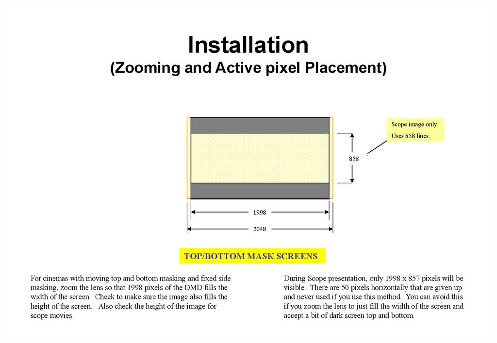
Installation(Zooming and Active pixel Placement)
Scope image only
Uses 858 lines.
858
1998
2048
TOP/BOTTOM MASK SCREENS
For cinemas with moving top and bottom masking and fixed side
masking, zoom the lens so that 1998 pixels of the DMD fills the
width of the screen. Check to make sure the image also fills the
height of the screen. Also check the height of the image for
scope movies.
During Scope presentation, only 1998 x 857 pixels will be
visible. There are 50 pixels horizontally that are given up
and never used if you use this method. You can avoid this
if you zoom the lens to just fill the width of the screen and
accept a bit of dark screen top and bottom.
6.
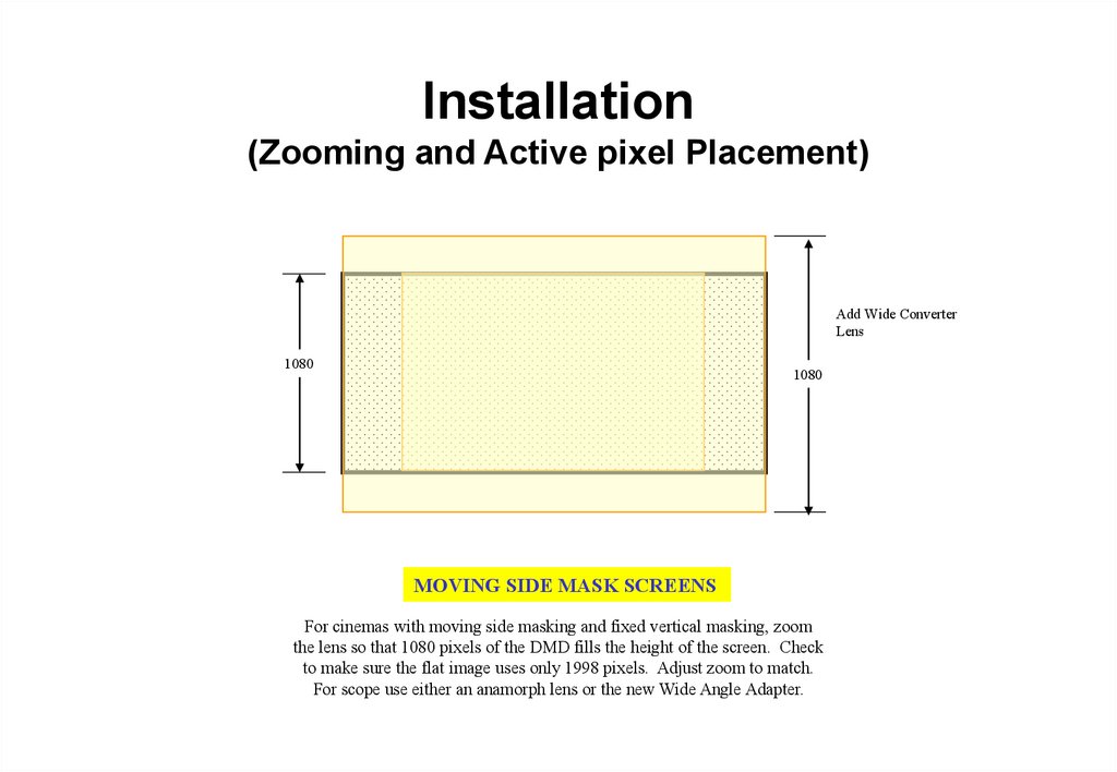
Installation(Zooming and Active pixel Placement)
Add Wide Converter
Lens
1080
1080
MOVING SIDE MASK SCREENS
For cinemas with moving side masking and fixed vertical masking, zoom
the lens so that 1080 pixels of the DMD fills the height of the screen. Check
to make sure the flat image uses only 1998 pixels. Adjust zoom to match.
For scope use either an anamorph lens or the new Wide Angle Adapter.
7. Optional Cine-IPM 2K
ControlRS232 IN/OUT
RS422
GPIO
Ethernet
Wired Remote
TPC (via rear RS232)
Inputs
Optional Input Cards
1 - RGBHV
2 - DVI
3 – Composite Video
4 – S-Video
5 – Option Card
6 – Option Card
Dual SDI/HDSDI
RGBHV
DVI
DO NOT CONNECT RS232 AT BACK
OF CINE-IPM2K TO RS232B OF ZX
PROJECTOR
8. Installation
General Overview
1.
2.
3.
4.
5.
6.
7.
8.
9.
Unpack and wheel pedestal to approximate location
Add projection head to pedestal
Position CP2000 at port window (leave approx. 2 ft. from wall)
Connect pre-installed internal cabling (pedestal-to-head)
Install sources/controllers/servers etc.
Connect lamp leads (pedestal-to-head).
Install lamp, TPC, and lens
Fill liquid coolant (50/50 antifreeze, only required on “s” )
Connect to exhaust ducting
a. Verify 600 CFM. Ft/min x 0.34 = CFM (1765
Ft/min)Minimum
9. Installation
General Overview—Continues
10. Verify AC selector setting on Ballast.
11. Initial 3-phase power-up
a. Set local date/time
b. Enter “New Lamp” details
c. Ensure to select proper lamp type
12. Adjust zoom lens for proper sizing. See separate discussion on lens
selection.
13. Optimize light output
a. Auto Lamp Alignment (after 20 minutes warmup)
b. Set (MCGD) Measured Color Gamut Data
c. Calibrate screen for 14fL (use “DCIXYZWhite_12bit” pattern)
13.Optimize Focus and Boresight
14.Backup conf.dat files or setup “Custom” page settings
15.Test flat and scope content.
10. Installation (Bolt Projection Head to Pedestal)
Locate pedestal to approximately 2 feet from port window (or move after assembly)
Extend rear safety prop
Lift head onto pedestal — requires 4 people
4 rods (head) into 4 holes (pedestal)
Retract safety prop and secure rods with 4 washers/nuts
1.
Safety prop
Elevates
rear of
head
until
fingers are
safely out of
the way
2.
4 rods
into
holes
in frame
3.
Retract
safety
prop
fully
4.
With head
in place,
secure
4 rods.
¾” wrench
11.
Installation(AC Mains Input Options)
The AC Mains Input for the CP2000-M and series 2 ZX projectors provides an option
to connect a separate UPS to power the electronics of the projector.
OR
UPS
1 Single phase 240VAC
1 Single phase 240VAC
For Lamp Ballast Only
240VAC single phase for
other electronics.
12. Installation (Connect Lamp Leads “S” model only)
• Route lamp cables up from pedestal• Connect positive (white) cable to
igniter terminal and ensure PCB is on
top of the cable and below the lock
washer.
• White cable lead must be routed
towards the back as shown in picture.
• PCB may not be up-side-down as
shown.
13. Installation (Connect Lamp Leads “S” model only)
Lamp CoolingCompartment
Open lamp cooling
compartment
Reflector
Door
Lamp Cooling
Compartment
Reflector
Route negative (black)
lamp lead into lamp area
Firewall Hole
(to igniter area)
m
Fro
Ballast
14. Installation (Connect Lamp Leads “S” model only)
• Secure negative (black)lamp lead — along with the
2 other wires from the
igniter area — to the lamp
connector nut.
• Make sure lamp lead is on
FIRST, then other 2 smaller
cables last.
From
Igniter “5”
From
PCB
From
Ballast
Secure all
15. Installation (Installing Lamp )
CP2000-ZXAnode
Connector
Reflector
Lamp
Cradle
CP2000-X/S
16. Installation (Install Lamp)
Allen head 5/32
Secure lamp at cathode
Slip anode connector on and secure
Secure anode connector
Note:
Reflector
!
Secure cathode connector
Lamp
Cradle
Allen head 9/64
Note: Additional adapter is required to
use CDXL30-SD lamp on CP2000-ZX
Take care when using
CDXL-30SD lamp.
Anode sleeve has
bevelled edge that will
catch at the lamp
cradle. Rotate lamp
until bevelled edge
does not interfere with
cradle.
17. Installation (Connect Water hoses)
Projection Head Hosesnon-operator’s side
warm
operator’s side
cool
NOTE:
warm
heat exchanger
reservoir
Depress while
inserting hose
end
cool
From Projection Head
non-operator’s side
operator’s side
From Pedestal
Pedestal Hoses
pump
to reservoir
from heat
exchanger
18. Installation (Fill Reservoir, required for Pedestal Units only)
Fill completely — no need
to watch gauge
½ Water
½ Ethylene Glycol
Second fill will be needed
after the head has been
power-up for a few
minutes. (check for air
bubbles and squeeze tube
to remove air)
Fill twice!
Use a low Silica Ethylene Glycol mixed
with distilled or de-ionized water (50/50).
NOTE: The capacity of the
reservoir is approximately
½ that of the cooling system.
19. Installation (Install Lens)
1.Insert Lens
Clamp
Open
CP2000-ZX
Notches at top
Push lens all
the way back
into projector
— there are
2 notches.
2.
Turn & Lock
Lock with
clamping
lever
If you experience slight
vibration in image, check the
exhaust fans to make sure it is
not causing the problem. If
vibration still occurs, there are
2 small slotted screws at the
top of the lens mount that you
can tighten. Remember to
loosen these next time you
remove the lens.
Clamp
Locked
CP2000-M/MR
When installing HC lens
in ZX, you need to take
note of the up position of
the lens and rotate the lens
after in has been fully
seated so that “up” is
pointing upwards.
20. Installation (Boresight or top/bottom, side/side focus)
CP2000-ZX/XB/SBTools: 3/16 + (3mm or 7/64) Allen key
Ensure image is centered and focused before proceeding.
Vertical Boresight: Using a 3mm or 7/64 Allen key, loosen the Set
screw to allow the Adjust screw to travel. Turn the Adjust screw until
the top and bottom focus is equal. You may need to play with the
center focus settings.
Horizontal Boresight: Use the same procedure as for Vertical
Boresight. You may need to go back to the Vertical adjustment as
there are some interaction between the two.
After all adjustments are complete, remember to tighten the Set
screw for both Vertical and Horizontal.
21. Installation (Boresight or top/bottom, side/side focus)
CP2000-MTools: 5mm Allen key
Vertical Boresight: To adjust Top/Bottom focus, start by loosening the
Set screw beside the Adjust screw. Turn the Adjust screw 1/8 of a turn
in one direction. Now turn both Right and Left Adjust screw, 1/16 of a
turn in the opposite direction. Continue this procedure until you are
satisfy with the focus.
Horizontal Boresight: To adjust the Left/Right focus, start by
loosening both Set screws beside the Adjust screw. Start with the right
side of the picture and turn the Right Adjust screw 1/16 of a turn. Now
turn the Left Adjust screw in the opposite direction the same amount.
Continue this procedure until the right side is in focus compare to the
middle. Repeat the
Once both Vertical and Horizontal Boresight has been
completed, remember to tighten the Set screw beside the Adjust
screw for all 3 group of screws.
22.
Installation(Install Lens)
CP2000-M Lens Calibration
Any time a new lens is installed on a CP2000M, you must “Calibrate” the lens motors for
proper ILS operation.
Press the “Calibrate” button. This procedure
takes approximtely 2 minutes.
It is also a good idea to enable the “Lens
Reset On Startup” function. This will ensure
the lens returns to the same point as it was
programed to even if someone has
accidentally bumped into it.
23. Installation (Head and Pedestal Interconnections “SB” model only)
Top Sec tion1
2
4
3
5
Pedestal
9
6
7
8
1.
Water hoses
2.
AC (front)
3.
Ethernet (from Hub)
4.
9-pin Control (front)
5.
15-pin Interconnect
6.
9-pin Control (back)
7.
AC (Back)
8.
Touch Panel Controller
9.
Lamp DC Power
24. Installation (Exhaust)
Lamp PowerMinimum Extraction
2 - 3KW
450 CFM or 212 l/s
4 – 6KW
600CFM or 283 l/s
Use the higher 600 CFM rating for systems installed in
small, poorly ventilated rooms. Remember if you have 3D,
use this lamp rating for calculations.
Change weight on flow switch if necessary (i/h/x/s/xb/sb)
Exhaust
Duct to
Outside
600 cfm
required
25. Installation (Enter Lamp Data)
Enter New Lamp Type and Serial number. The “Type” will tell the projector
what power settings to use. After installing new lamp, projector will keep track
of usage hours.
CP2000-ZX
26.
Installation(Main Menu)
Lamp On/Off
Press and hold for 1 second
CP2000-ZX/M
Mechanical Shutter On/Off
Listen for “clunk” noise if
in doubt
Test Patterns List
Patterns added in
Advanced Menu
Login: (CP2000-X/S)
User = service
Password = tpccds
Click again to remove
advanced features
Login: (CP2000-ZX/M)
User = service
Password = service
27. Installation (Enter Lamp Hour Limit)
Enter lamp hour limit to receive a lamp replacement warning message.
Lamp
CDXL-20
CDXL-30
CDXL-30SD
CDXL-45
CDXL-60
Hour Limit
2400
1440
1100
900
500
28.
Touch Panel Controller (TPC)(Custom setup files)
Inputs:
292-A or B (Typical Mpeg servers)
292-Dual (used in JPEG2K 4:4:4)
DVI - A, B, Twin (3rd party processors)
Cine-IPM - A, B, Twin (Inputs 1, 2, ..6)
Cine-IPM - A, B, Twin (Channels 1, 2, …)
Synchronizes head activity with TPC
Use Cinema Path for all
D-Cinema sources.
Click after you load/delete files from head
Target Color: (TCGD)
P7v2 – Telecine, Theatre (Old standard)
DCI_XENON (New standard for Mpeg servers)
DCI_XYZE_314_351 (Standard for JPEG servers)
Rec. 709 (Standard HDTV)
SMPTE C (Standard Broadcast)
Data Format:
422 Unpacked 10Bit, O/E Pixels
422 Unpacked 10Bit, O/E Lines
422 Packed 12 Bit, O/E Pixels
422 Packed 12 Bit, O/E Lines
444 Unpacked 10 Bits
444 Packed 10 Bits, Mixed
444 Packed 10 Bits, O/E Pixels
444 Packed 12 Bits
422 Unpacked 10 Bit, O/E Frames
Color Space: (CSC)
YCbCr240M (Standard 292 inputs)
RGB (Standard DVI inputs or Dual 292 4:4:4)
Unpacked 8 Bit (for DVI inputs)
Twin packed 10 Bit (for Twin-DVI)
Source:
Auto Square Pixels (assume no squeeze)
H x V Aspect ratio (e.g. 1920 x 1080 1.77)
Aspect ratio 0 = square pixels
Gamma: (LUT-DG)
Gamma 2.6 (Standard D-Cinema)
Pal (Standard Video format)
This Tab will only
appear if projector is
3D capable.
29.
Touch Panel Controller (TPC)(Custom setup files)
Screen:
Sets Masking and Anamorph Type
Measured Color: (MCGD)
Typically use “OnSite” as label
LUT – CLUT:
Also known as 3D color lookup table
Linear_9x9x9 (Standard D-Cinema)
Others created by Post Production Houses
30.
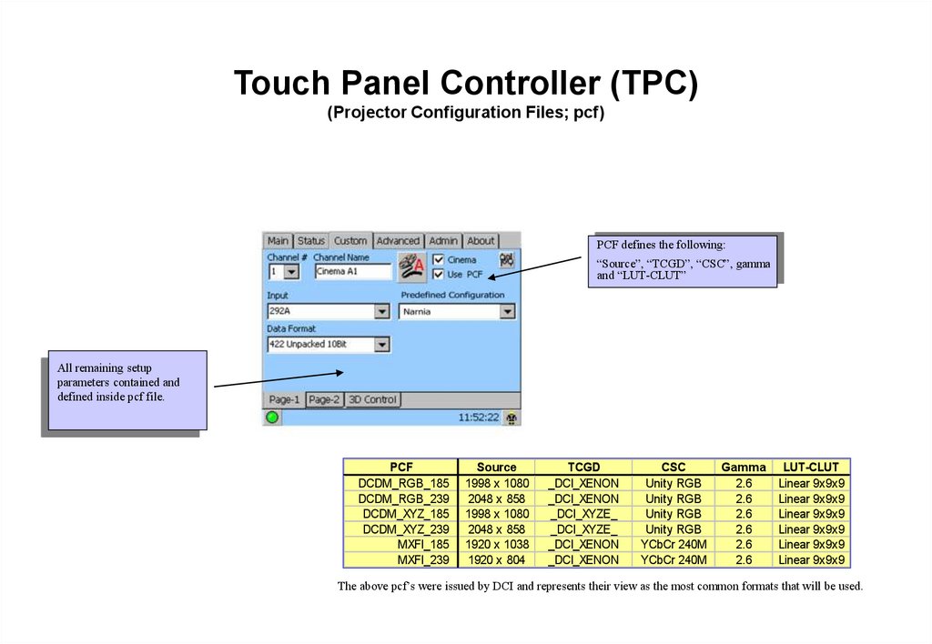
Touch Panel Controller (TPC)(Projector Configuration Files; pcf)
PCF defines the following:
“Source”, “TCGD”, “CSC”, gamma
and “LUT-CLUT”
All remaining setup
parameters contained and
defined inside pcf file.
PCF
DCDM_RGB_185
DCDM_RGB_239
DCDM_XYZ_185
DCDM_XYZ_239
MXFI_185
MXFI_239
Source
1998 x 1080
2048 x 858
1998 x 1080
2048 x 858
1920 x 1038
1920 x 804
TCGD
_DCI_XENON
_DCI_XENON
_DCI_XYZE_
_DCI_XYZE_
_DCI_XENON
_DCI_XENON
CSC
Unity RGB
Unity RGB
Unity RGB
Unity RGB
YCbCr 240M
YCbCr 240M
Gamma
2.6
2.6
2.6
2.6
2.6
2.6
LUT-CLUT
Linear 9x9x9
Linear 9x9x9
Linear 9x9x9
Linear 9x9x9
Linear 9x9x9
Linear 9x9x9
The above pcf’s were issued by DCI and represents their view as the most common formats that will be used.
31.
Touch Panel Controller (TPC)(3D)
Sets whether port A is left eye or right eye.
# frames Display : # frames Input
(Typical input = 24fps; 6:2)
Max frame rate ~ 144Hz.
Input sync signal used by GPIO
connector. Most dual signal system
do not require separate sync input.
Determines if the left or right eye is the
dominant or frame leading trigger for motion.
If set wrong, static images may appear okay
but motion will appear jerky.
L/R Display Reference not used. This
information is either in the source or the
Input GPI signal.
Output polarity of sync signal should be
matched to L/R dominance frame. If set
wrong, left eye sees right eye image.
(i. e. set to “None”)
Related to Display Reference which
is not used by dual signal systems
Sync pulse used to trigger IR
transmitters or “Z” screens. Check
GPIO connector to match.
Dark Time and Output Delay together varies the
sync pulse to reduce image ghosting or crosstalk.
Dark Time Range: 388 – 4500 for 4:2
Dark Time Range: 388 – 2500 for 5:2
Output Delay Range: +/- 2000us for 4:2
Output Delay Range: +/- 200us for 5:2
Output Delay (P): not supported
If this menu is missing on your TPC, then the projector may not have an EFIB installed. Check the “About” tab to see if FIB or EFIB is installed.
32. Touch Panel Controller (TPC) (Lamp Control)
Lamp Current Range:(requires TPC 2.4d firmware or higher)
2D = 12 - 14 fL (41 – 48
cd/m2).
3D = (~30 fL before filters)
CP2000-ZX
LiteLOC: Select “Enable” to
use. Projector will
automatically adjust Lamp
Power to track light output as
lamp ages. Click “Set”
periodically to reset the target
point.
LampLOC optimises
alignment between lamp and
reflector. Use when installing
a new lamp and periodically
as lamp ages. Allow lamp to
warm up before using.
Lamp
2KW
3KW
4.5KW
6KW
75%
66
82
112
126
110%
98
128
160
180
33. Touch Panel Controller (TPC) (Colour or Gamut settings)
MCGD System must becalibrated on site. Usually
performed during installation
and checked anually. You
may need to create 2 MCGD
file: 2D and 3D
If desired, TCGD’s can be
manually created here. More
likely, use this menu to
identify the exact x,y values
of the target color used.
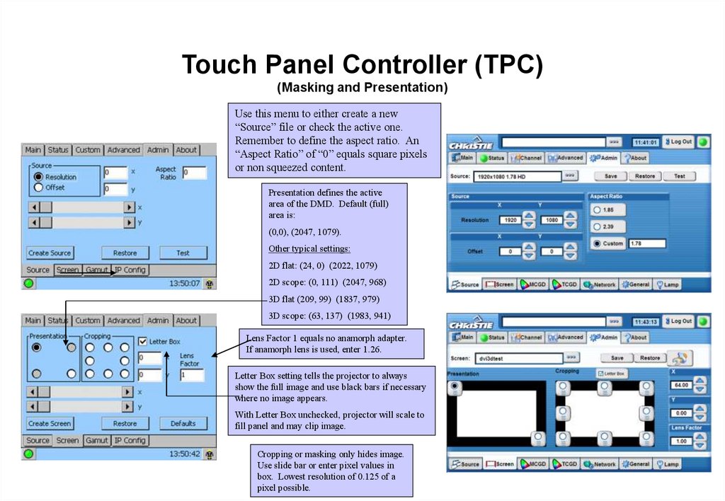
34.
Touch Panel Controller (TPC)(Masking and Presentation)
Use this menu to either create a new
“Source” file or check the active one.
Remember to define the aspect ratio. An
“Aspect Ratio” of “0” equals square pixels
or non squeezed content.
Presentation defines the active
area of the DMD. Default (full)
area is:
(0,0), (2047, 1079).
Other typical settings:
2D flat: (24, 0) (2022, 1079)
2D scope: (0, 111) (2047, 968)
3D flat (209, 99) (1837, 979)
3D scope: (63, 137) (1983, 941)
Lens Factor 1 equals no anamorph adapter.
If anamorph lens is used, enter 1.26.
Letter Box setting tells the projector to always
show the full image and use black bars if necessary
where no image appears.
With Letter Box unchecked, projector will scale to
fill panel and may clip image.
Cropping or masking only hides image.
Use slide bar or enter pixel values in
box. Lowest resolution of 0.125 of a
pixel possible.
35. Installation (Leveling and Tilting)
Lens
barrel
Adjust lens shift and look
into the front of the lens
to ensure image is not
being cut by lens barrel.
Reduce lens shift if image
is blocked by the lens.
You will then have to tilt
and pivot the projector to
align the image back onto
the screen.
Add Masking
Image being
clipped by
lens barrel.
Turn to
adjust
height
7/8” wrench
36. Installation (Setting IP Address)
CP2000-ZXYou may need to change the default IP Address of
the projector head and controller (e.g. TPC or PCM).
Use the menus shown above to do this.
Both projector head and Touch Panel needs to be
power cycled for changes to take place.
Default IP address: DLP IP – 192.168.206.10
Remote Controlling: You may need to
set the Remote Access Level to “Free
Access” if you wish to control the
projector via a Server or Third party
controller which does not have password
authenticated commands.
TPC or PCM – 192.168.206.110
37.
Installation(CP2000-ZX/M I/O Connections)
Used for general serial communication
to Projector. Not to be used for CineIPM2K or connections directly to the
“head”. RS232 A is located to the left
of this panel and is dedicated to serial
connection to T.I. electronics.
Connect to System
Ethernet Switch or Hub.
Not used at the moment.
38. Installation (Cine-IPM 2K)
Projectors with FIB will loose 15lines top and 15 lines bottom.
Projectors with EFIB will loose no
lines but must be set to nonCinema path.
Output of Cine-IPM 2K is
selectable:
1280 x 720
1280 x 1024
1400 x 1050
1920 x 1080
2048 x 1080
Make sure you set the Projectors
Source and Data Format to match.
39.
Maintenance40. Maintenance (Proper Cooling)
Standard precautions
Air filter
Some environments are not “sealed” and the main filter becomes clogged
regularly.
Replaced air filters every lamp change or more as required. Check
monthly.
Liquid Cooler
Avoid crowding with other equipment
Keep louvers & vents clear and away from other heat sources
Check coolant level every month.
Coolant is 50/50 distilled water and ethylene glycol (antifreeze)
CP2000-M also has a washable filter for the radiator.
Exhaust Duct
No kinks or obstructions
41.
Maintenance(Cleaning; dust, dirt, oil)
Electrical: AC connections
Check every 60 days or 500 hours:
Contact surfaces of anode and cathode connections
Look for heat fatigue on metal surfaces (discolouration)
All other connections tight?
Optical See CP User’s Manual
Avoid unnecessary cleaning! Damage possible!
Check LENS and LAMP REFLECTOR only
IF DUSTY LENS
1.
2.
3.
4.
Camel-hair brush
Compressed air (filtered nitrogen through anti-static nozzle)
Microfibre cloth if dust is bound to surface. No pressure.
Lens cleaning solution only if necessary
IF FINGERPRINTS, SMUDGES, OIL ON LENS
1. Camel-hair brush or compressed air first
2. Damp lens tissue with lens cleaning solution, wrap around cotton
swab
42.
Maintenance(Cleaning; dust, dirt, oil)
• Optical Continued
Other Cleaning
Lamp fan
Igniter
Air flow interlocks (lamp fan and exhaust opening)
43. Lamp Replacement Schedule
Warranties for CDXL lamps
2.0 Kw
3.0 kW
4.5 kW
6.0 kW
[ 60 hours full warranty, 61 - 1200 pro-rated ]
[ 720 hours full warranty, 721 - 1440 pro-rated ]
[ 60 hours full warranty, 61 - 900 pro-rated ]
[ 50 hours full warranty, 51 - 500 pro-rated ]
Never exceed warranted life by more than 20% (safety)
Lamp age is tracked in proj. Can also record on card provided.
44. Main Filter Replacement
1. Open filter door2. Open or remove door
3. Remove old filter
4. Install new filter, tabs out
5. Filter installed
6. Shut filter door (magnetic closure)
Replace Main Filter with
each lamp change!
45. Temperature Limits
DeviceWarning
Critical
Card Cage
DMD – Blue
DMD – Red
Integrator
Prism
SSM
55-69
50-54
50-54
95-104
70-74
55-59
70
55
55
105
75
60
46.
Interface Board Hardware LEDsLED Identifier
Short Description
Full Description
D3
DOC Active
Indicates Disk-On-Chip read or write activity
D4
Ethernet TX
Indicates Ethernet transmit activity from the board
D5
Ethernet RX
Indicates all Ethernet activity on the connected LAN, including,but not limited to, data
intended for the board
D6
Ethernet SPD
Indicates the speed of the Ethernet link (if present)OFF = 10Mbit ; ON = 100Mbit
D7
Ethernet LNK
Indicates the presence of a link to an external deviceOFF = Link Not Present ; ON = Link
Present
D8
Ethernet COL
D9
Ethernet FDX
Indicates recent Ethernet collisions. While this is an error, itcan occur during normal
operation of a LAN when there are multiple devices attempting to transmit at the same
time. This is usually corrected at the hardware layer by the normal Ethernet
protocol.Occasional and brief collision indications are not usually a problem.OFF = No
Collision ; ON = Collision
Indicates full duplex Ethernet (not important)OFF = Not Full Duplex ; ON = Full Duplex
D12
Fuse Fail
Indicates that fuse F1 is blown. Fuse F1 protects the input to the 1.5V switching
regulator.OFF = Fuse OK ; ON = Fuse Blown
D13
Software Fail
Indicates that the FPGA has not loaded, or that the CPU watchdoghas timed out.OFF =
OK ; ON = Fail
47.
Interface Board Hardware LEDs (continues)LED Identifier
Short Description
Full Description
D14
5VDC OK
Indicates that the 5VDC supply is nominally greater than 4.65VDCOFF = Fail ; ON = OK
D15
3.3VDC OK
Indicates that the 3.3VDC supply is nominally between 3.06VDC and 3.52VDCOFF =
Fail ; ON = OK
D16
1.5VDC OK
Indicates that the 1.5VDC switching regulator is operating properlyOFF = Fail ; ON = OK
D17
Supply Fail
Indicates that one or more of the power inputs has failedOFF = OK ; ON = FAIL
D18
Hardware Fail
Indicates that the ARM software has declared an error.OFF = OK ; ON = FAILConditions
that will be indicated by this LED:•This LED will be illuminated during system
initialization. If any part of the initialization fails, LED will remain illuminated.•This LED
will illuminate during system operation if an error occurs that puts the system in a state
that is less than fully functional. An example would be the loss of communication with the
cinema processor board.This LED will illuminate during system operation if an error
occurs where the setup of the electronics does not match the last user request. An example
of the would be if active data could not be made active in the electronics. If this occurs,
the user should examine the System Status and Error Logs.
48.
Processor Board Hardware LEDsLED Identifier
Short Description
Full Description
D3
Local Power Good
Indicates the on-board 1.8VDC and 1.5VDC regulators are operating properlyOFF = FAIL
; ON = OK
D4
3.3VDC Supply
Indicates presence of external 3.3VDC supplyOFF = FAIL ; ON = OK
D5
5VDC Supply
Indicates presence of external 5VDC supplyOFF = FAIL ; ON = OK
D6
12VDC Supply
Indicates presence of external 12VDC supplyOFF = FAIL ; ON = OK
D7
Flash V_ID Mode
Indicates that FLASH memory is in an unprotected stateOFF = Protected ; ON =
Unprotected•FLASH memory protection is not being used, therefore, this LED has no
meaning.•In certain Series-0 Pre-Production Processor boards (with MSN numbers
starting with “0123”), FLASH protection of some sectors was used. Updating the FLASH
onthese boards required using the “TEMP UNPROTECT”button which would unprotect
the FLASH and illuminate this LED.
D8
Diagnostic Fail
Indicates that built-in diagnostic test failed. See System Status for details on which test
failedOFF = OK ; ON = FAIL