
 Промышленность
Похожие презентации:


Furnaces bases operation
1.
FURNACES BASESOPERATION
Th Roustan DT Melting 09/2021
2.
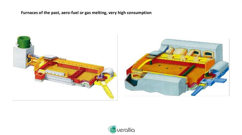
Furnaces of the past, aero-fuel or gas melting, very high consumption3.
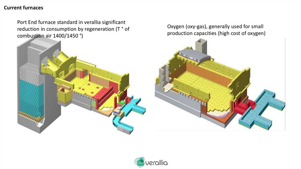
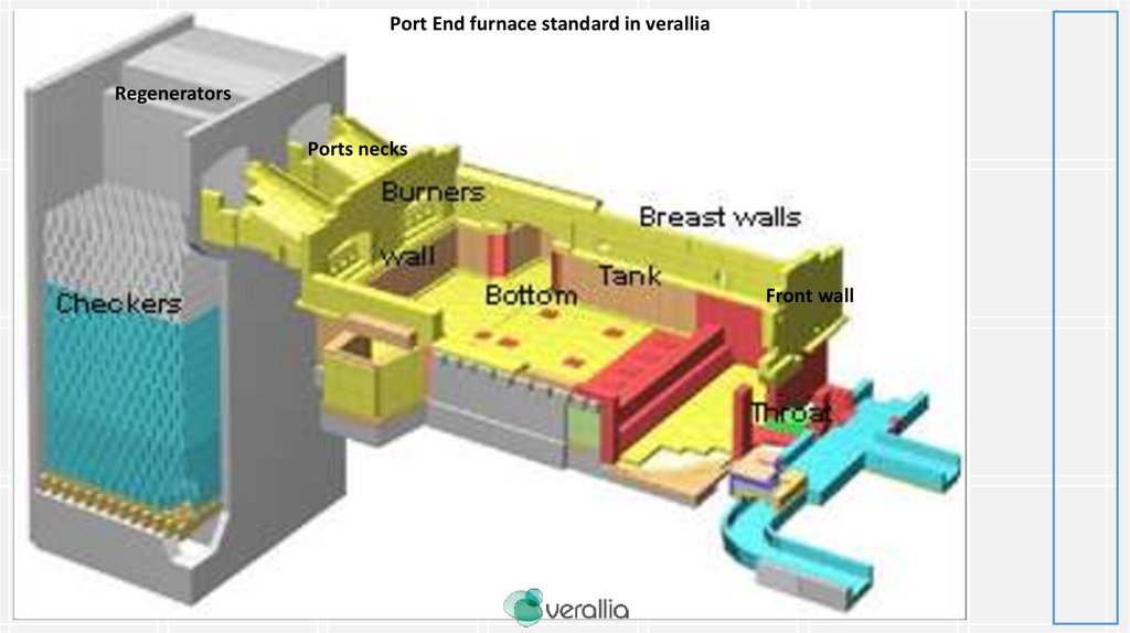
Current furnacesPort End furnace standard in verallia significant
reduction in consumption by regeneration (T ° of
combustion air 1400/1450 °)
Oxygen (oxy-gas), generally used for small
production capacities (high cost of oxygen)
4.
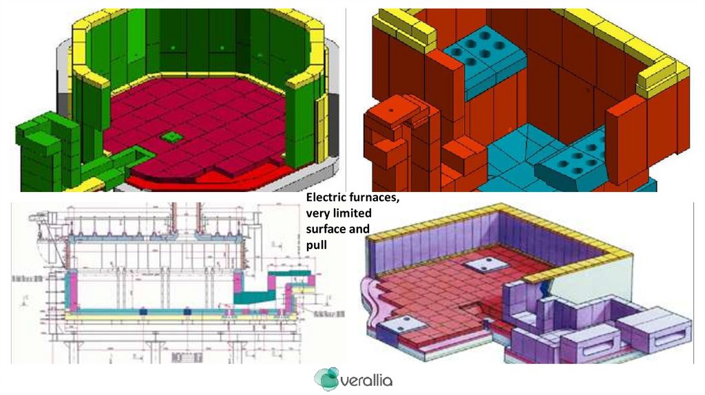
Electric furnaces,very limited
surface and
pull
5.
Port End furnace standard in veralliaRegenerators
Ports necks
Front wall
6.
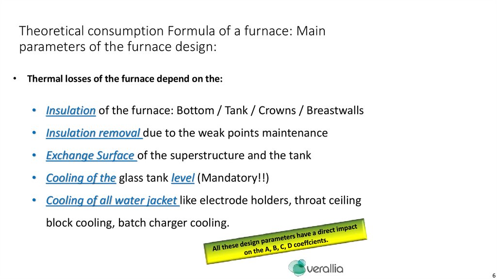
Theoretical consumption Formula of a furnace: Mainparameters of the furnace design:
• Thermal losses of the furnace depend on the:
• Insulation of the furnace: Bottom / Tank / Crowns / Breastwalls
• Insulation removal due to the weak points maintenance
• Exchange Surface of the superstructure and the tank
• Cooling of the glass tank level (Mandatory!!)
• Cooling of all water jacket like electrode holders, throat ceiling
block cooling, batch charger cooling.
6
7.
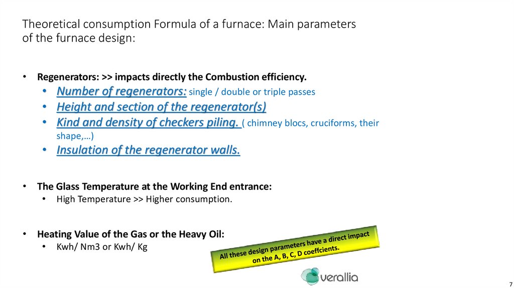
Theoretical consumption Formula of a furnace: Main parametersof the furnace design:
• Regenerators: >> impacts directly the Combustion efficiency.
• Number of regenerators: single / double or triple passes
• Height and section of the regenerator(s)
• Kind and density of checkers piling. ( chimney blocs, cruciforms, their
shape,…)
• Insulation of the regenerator walls.
• The Glass Temperature at the Working End entrance:
High Temperature >> Higher consumption.
• Heating Value of the Gas or the Heavy Oil:
Kwh/ Nm3 or Kwh/ Kg
7
8.
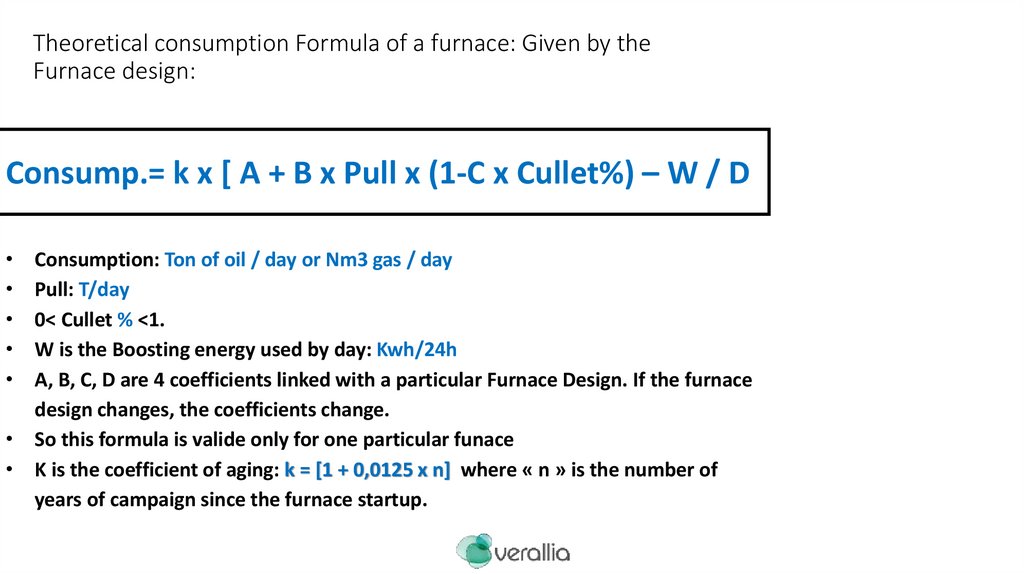
Theoretical consumption Formula of a furnace: Given by theFurnace design:
Consump.= k x [ A + B x Pull x (1-C x Cullet%) – W / D
Consumption: Ton of oil / day or Nm3 gas / day
Pull: T/day
0< Cullet % <1.
W is the Boosting energy used by day: Kwh/24h
A, B, C, D are 4 coefficients linked with a particular Furnace Design. If the furnace
design changes, the coefficients change.
• So this formula is valide only for one particular funace
• K is the coefficient of aging: k = [1 + 0,0125 x n] where « n » is the number of
years of campaign since the furnace startup.
9.
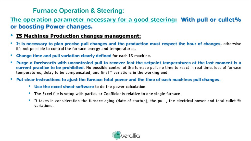
Furnace Operation & Steering:The operation parameter necessary for a good steering: With pull or cullet%
or boosting Power changes.
IS Machines Production changes management:
It is necessary to plan precise pull changes and the production must respect the hour of changes, otherwise
it’s not possible to control the furnace energy and temperatures.
Change time and pull variation clearly defined for each IS machine.
Purge a forehearth with uncontroled pull to recover fast the setpoint temperatures at the last moment is a
current practice to be prohibited. No possible control of the furnace pull, no time to react in real time, loss of furnace
temperatures, delay to be compensated, and final T variations in the working end.
Put clear instructions to ajust the furnace total power and the time of each machines pull changes.
Use the excel sheet software to do the power calculation.
The Excel file is setup with particular Coefficients relative to one single furnace .
It takes in consideration the furnace aging (date of startup), the pull , the electrical power and total cullet %
variations.
10.
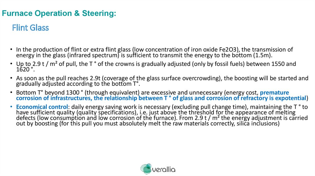
Furnace Operation & Steering:Flint Glass
• In the production of flint or extra flint glass (low concentration of iron oxide Fe2O3), the transmission of
energy in the glass (infrared spectrum) is sufficient to transmit the energy to the bottom (1.5m).
• Up to 2.9 t / m² of pull, the T ° of the crowns is gradually adjusted (only by fossil fuels) between 1550 and
1620 °.
• As soon as the pull reaches 2.9t (coverage of the glass surface overcrowding), the boosting will be started and
gradually adjusted according to the bottom T°.
• Bottom T° beyond 1300 ° (through equivalent) are excessive and unnecessary (energy cost, premature
corrosion of infrastructures, the relationship between T ° of glass and corrosion of refractory is expotential)
• Economical control: daily energy saving work is necessary (excluding pull change time), maintaining the T ° to
have sufficient quality (quality specifications), i.e. just above the threshold for the appearance of melting
defects (low consumption and low corrosion of the furnace). From 2.9 t / m² the energy adjustment is carried
out by boosting (for this pull you must absolutely melt the raw materials correctly, silica inclusions)
11.
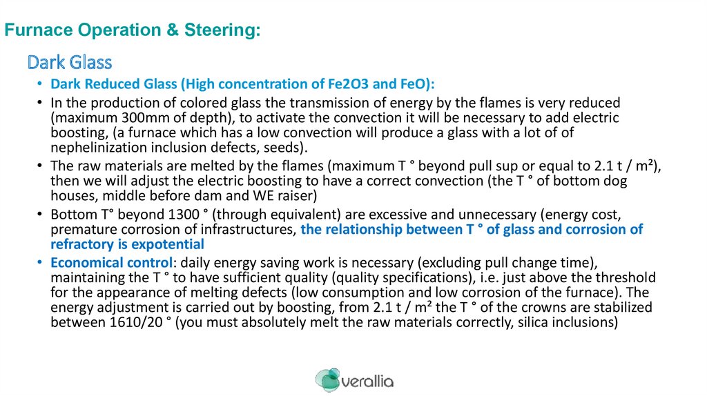
Furnace Operation & Steering:Dark Glass
• Dark Reduced Glass (High concentration of Fe2O3 and FeO):
• In the production of colored glass the transmission of energy by the flames is very reduced
(maximum 300mm of depth), to activate the convection it will be necessary to add electric
boosting, (a furnace which has a low convection will produce a glass with a lot of of
nephelinization inclusion defects, seeds).
• The raw materials are melted by the flames (maximum T ° beyond pull sup or equal to 2.1 t / m²),
then we will adjust the electric boosting to have a correct convection (the T ° of bottom dog
houses, middle before dam and WE raiser)
• Bottom T° beyond 1300 ° (through equivalent) are excessive and unnecessary (energy cost,
premature corrosion of infrastructures, the relationship between T ° of glass and corrosion of
refractory is expotential
• Economical control: daily energy saving work is necessary (excluding pull change time),
maintaining the T ° to have sufficient quality (quality specifications), i.e. just above the threshold
for the appearance of melting defects (low consumption and low corrosion of the furnace). The
energy adjustment is carried out by boosting, from 2.1 t / m² the T ° of the crowns are stabilized
between 1610/20 ° (you must absolutely melt the raw materials correctly, silica inclusions)
12.
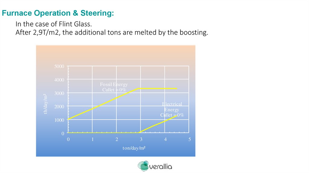
Furnace Operation & Steering:In the case of Flint Glass.
After 2,9T/m2, the additional tons are melted by the boosting.
5000
th/day/m²
4000
Fossil Energy
Cullet = 0%
3000
Electrical
Energy
Cullet = 0%
2000
1000
0
0
1
2
3
ton/day/m²
4
5
13.
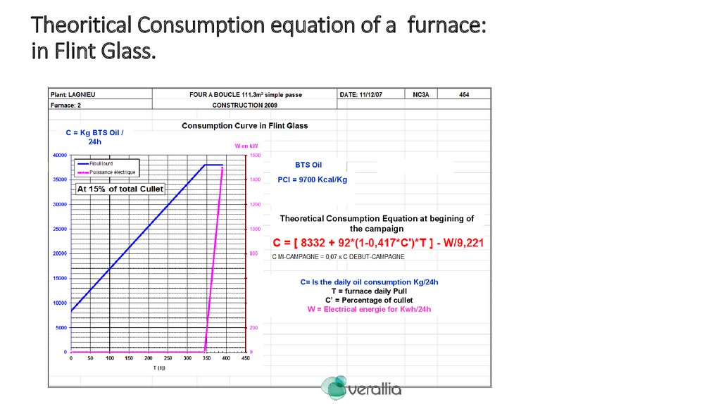
Theoritical Consumption equation of a furnace:in Flint Glass.
C = Kg BTS Oil /
24h
BTS Oil
PCI = 9700 Kcal/Kg
Theoretical Consumption Equation at begining of
the campaign
C= Is the daily oil consumption Kg/24h
T = furnace daily Pull
C’ = Percentage of cullet
W = Electrical energie for Kwh/24h
14.
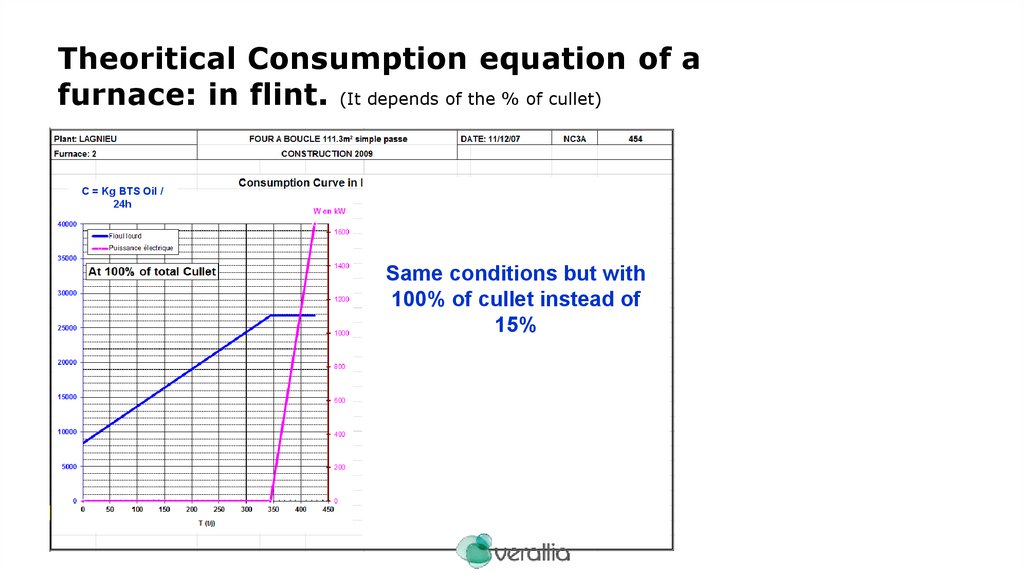
Theoritical Consumption equation of afurnace: in flint. (It depends of the % of cullet)
C = Kg BTS Oil /
24h
Same conditions but with
100% of cullet instead of
15%
15.
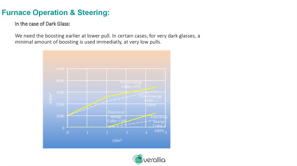
Furnace Operation & Steering:In the case of Dark Glass:
We need the boosting earlier at lower pull. In certain cases, for very dark glasses, a
minimal amount of boosting is used immediatly, at very low pulls.
5000
th/j/m²
4000
Fossil energy
Cullet = 0%
3000
Fossil energy
Cullet =
100%
2000
Electrical
energy
Cullet = 0%
1000
0
0
1
2
3
t/j/m²
Electrical
energy
Cullet =
100% 5
4
16.
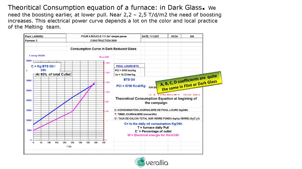
Theoritical Consumption equation of a furnace: in Dark Glass.We
need the boosting earlier, at lower pull. Near 2,2 – 2,5 T/d/m2 the need of boosting
increases. This electrical power curve depends a lot on the color and local practice
of the Melting team.
C = Kg BTS Oil /
24h
BTS Oil
PCI = 9700 Kcal/Kg
Theoretical Consumption Equation at begining of
the campaign
C= Is the daily oil consumption Kg/24h
T = furnace daily Pull
C’ = Percentage of cullet
W = Electrical energie for Kwh/24h
17.
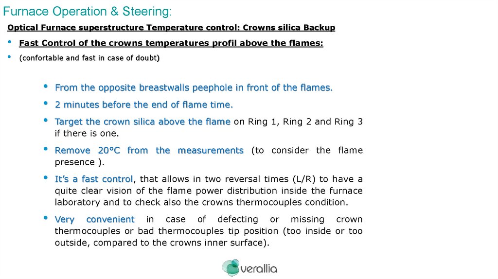
Furnace Operation & Steering:Optical Furnace superstructure Temperature control: Crowns silica Backup
Fast Control of the crowns temperatures profil above the flames:
(confortable and fast in case of doubt)
From the opposite breastwalls peephole in front of the flames.
Remove 20°C from the measurements (to consider the flame
presence ).
It’s a fast control, that allows in two reversal times (L/R) to have a
quite clear vision of the flame power distribution inside the furnace
laboratory and to check also the crowns thermocouples condition.
Very convenient in case of defecting or missing crown
thermocouples or bad thermocouples tip position (too inside or too
outside, compared to the crowns inner surface).
2 minutes before the end of flame time.
Target the crown silica above the flame on Ring 1, Ring 2 and Ring 3
if there is one.
18.
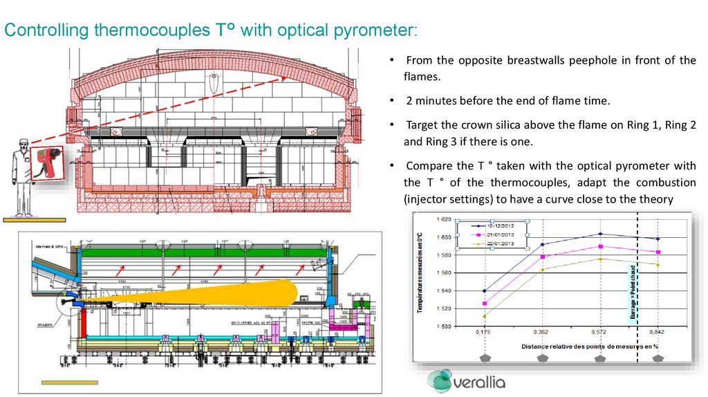
Controlling thermocouples T° with optical pyrometer:Optical
Furnace
Temperature
control:
Backup
superstructure
Crowns
silica
Fast
Control
of
the
crowns
temperatures
profil
above
the
flames:
(confortable and fast in case of doubt)
• From the opposite breastwalls peephole in front of the
flames.
• 2 minutes before the end of flame time.
• Target the crown silica above the flame on Ring 1, Ring 2
and Ring 3 if there is one.
• Compare the T ° taken with the optical pyrometer with
the T ° of the thermocouples, adapt the combustion
(injector settings) to have a curve close to the theory
19.
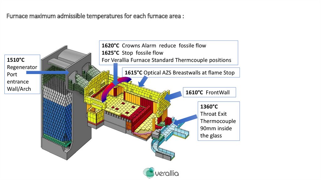
Furnace maximum admissible temperatures for each furnace area :1510°C
Regenerator
Port
entrance
Wall/Arch
1620°C Crowns Alarm reduce fossile flow
1625°C Stop fossile flow
For Verallia Furnace Standard Thermcouple positions
1615°C Optical AZS Breastwalls at flame Stop
1610°C FrontWall
1360°C
Throat Exit
Thermocouple
90mm inside
the glass
20.
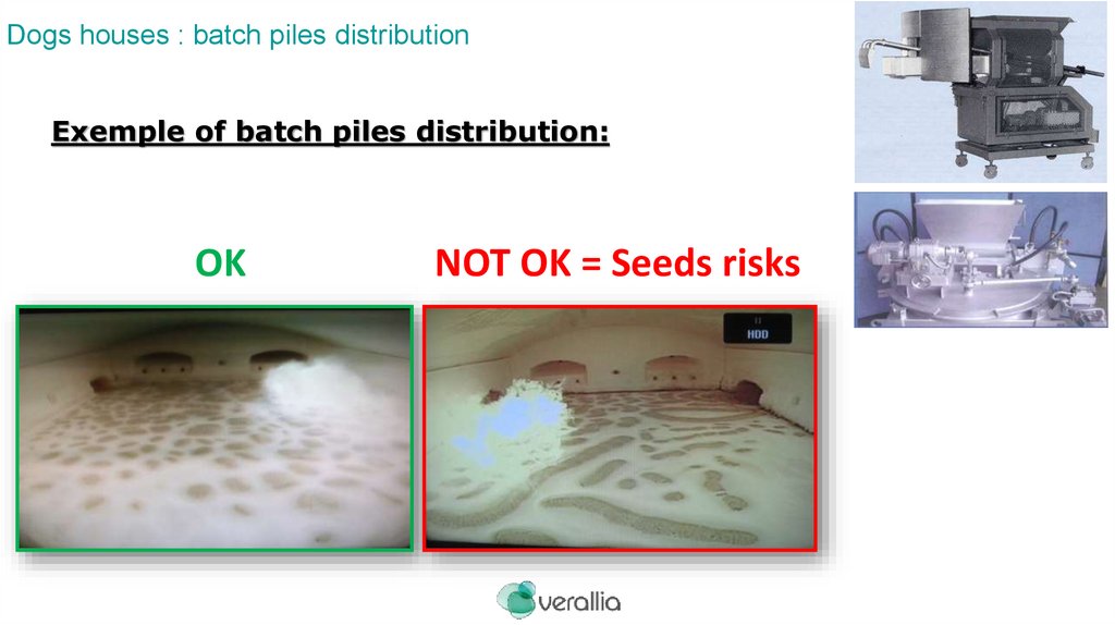
Dogs houses : batch piles distributionExemple of batch piles distribution:
OK
NOT OK = Seeds risks
21.
Furnace Operation & Steering:The operation parameters necessary for a good steering: At stable pull.
Which Furnace Steering Setpoints and Why:
On the superstructure:
Combustion parameters: (contrôle des NOx).
Specific thrust Mini – Maxi. (Adaptation of injection diameters)
Inclination / Azimut.
Condition of injectors: Cleanliness and status.
Fumes analyze at the port neck sides (CO 5000ppm maxi, NOx)
Fumes analyzes at the stach, with reaction standard procedure in
case of deviation on CO or NOx
Flame
shape
and
endoscope screen.
development
looking
at
the
front
wall
22.
Electric Boosting :The operation parameters necessary for a good steering: At stable pull.
Which Furnace Steering Setpoints and Why:
On the infrastructure: Tank bottom
Define a pilot thermocouple as the reference temperature (with a setpoint) to drive the
boosting: Ideally melting bottom thermocouple in front of the doghouses, distante from
the electrodes blocks.
The Electrical Power steering is operated following the evolution of the impedance of an
electrode group that changes when the average glass temperature evolves. (fine
tuning).
(Electrical power steering).
When the glass tank temperature decreases (the bottom temperature will
decrease very soon), the conductivity of the glass decreases, so the
impedance of the glass increases, so you must inject more tension to increase
the power, and increase the glass temperature.
+1°C bottom temperature -0,3 mOhm impedance.
-1°C bottom temperature +0,3 mOhm impedance.
It is the finest and fastest way to anticipate any bottom temperature drift!!
Define the step of maximale power variation (KW), and minimum delay before
adjusting the power setpoint another time.
23.
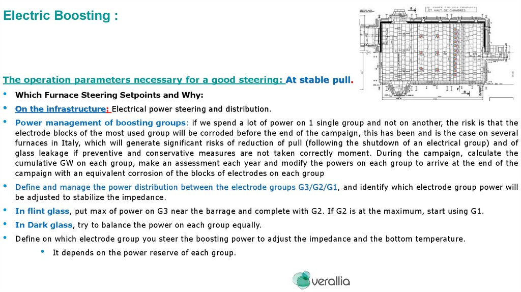
Electric Boosting :The operation parameters necessary for a good steering: At stable pull.
Which Furnace Steering Setpoints and Why:
On the infrastructure: Electrical power steering and distribution.
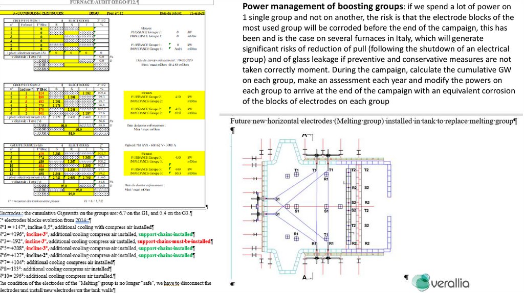
Power management of boosting groups: if we spend a lot of power on 1 single group and not on another, the risk is that the
electrode blocks of the most used group will be corroded before the end of the campaign, this has been and is the case on several
furnaces in Italy, which will generate significant risks of reduction of pull (following the shutdown of an electrical group) and of
glass leakage if preventive and conservative measures are not taken correctly moment. During the campaign, calculate the
cumulative GW on each group, make an assessment each year and modify the powers on each group to arrive at the end of the
campaign with an equivalent corrosion of the blocks of electrodes on each group
Define and manage the power distribution between the electrode groups G3/G2/G1, and identify which electrode group power will
be adjusted to stabilize the impedance.
In flint glass, put max of power on G3 near the barrage and complete with G2. If G2 is at the maximum, start using G1.
In Dark glass, try to balance the power on each group equally.
Define on which electrode group you steer the boosting power to adjust the impedance and the bottom temperature.
It depends on the power reserve of each group.
24.
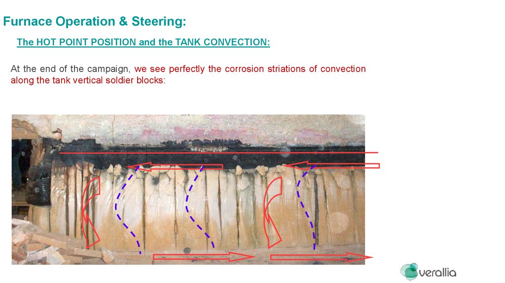
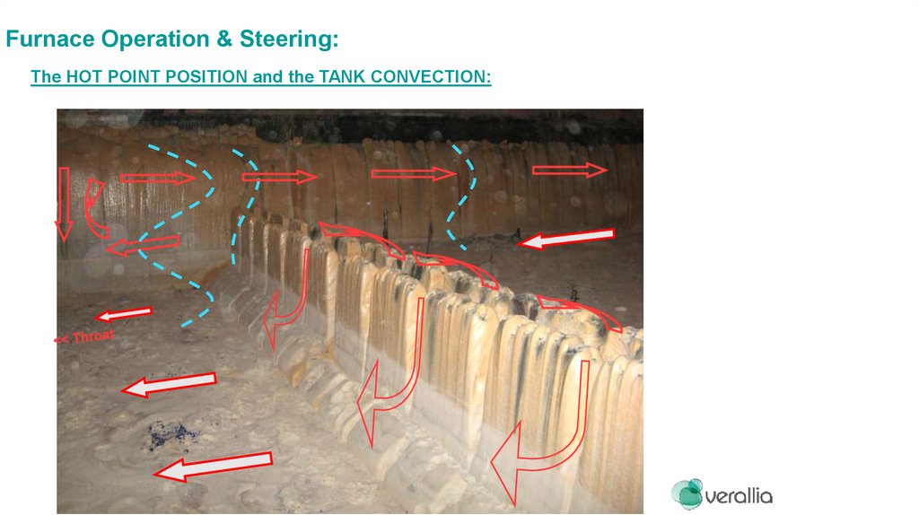
Furnace Operation & Steering:The HOT POINT POSITION and the TANK CONVECTION:
At the end of the campaign, we see perfectly the corrosion striations of convection
along the tank vertical soldier blocks:
D. Grand MP & EV 2012
25.
Furnace Operation & Steering:The HOT POINT POSITION and the TANK CONVECTION:
26.
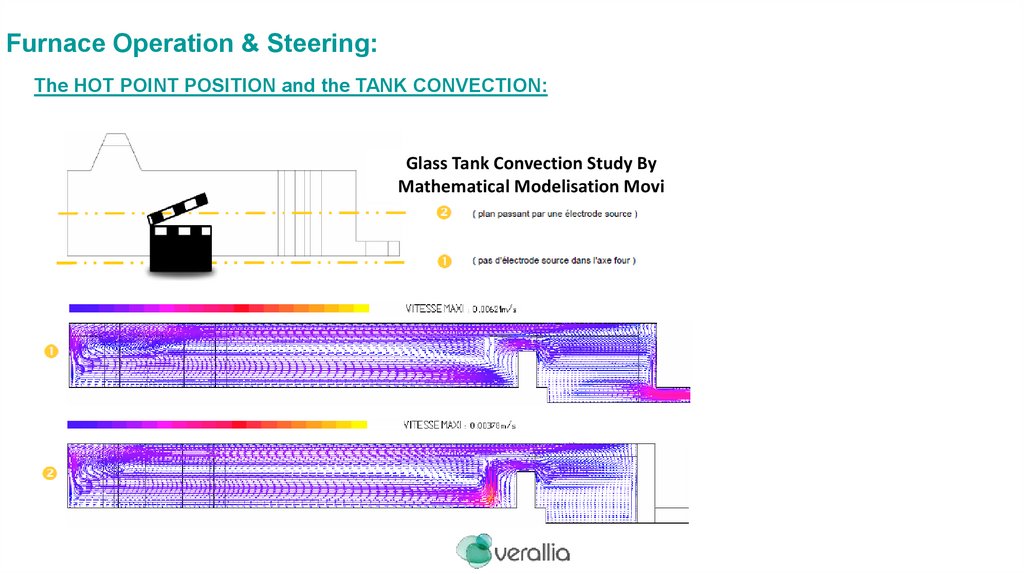
Furnace Operation & Steering:The HOT POINT POSITION and the TANK CONVECTION:
Glass Tank Convection Study By
Mathematical Modelisation Movi
D. Grand MP & EV 2012
27.
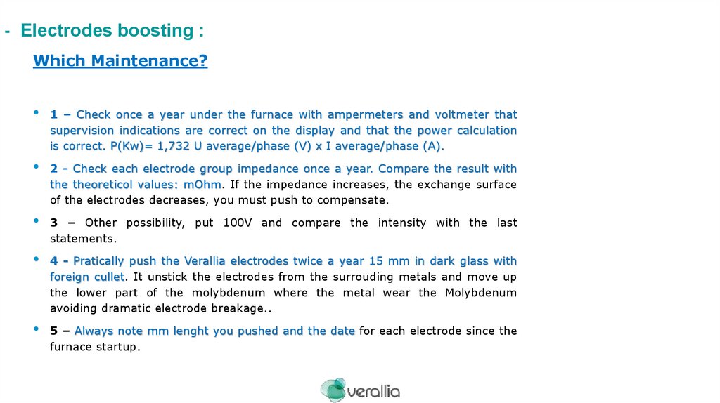
- Electrodes boosting :Which Maintenance?
1 – Check once a year under the furnace with ampermeters and voltmeter that
supervision indications are correct on the display and that the power calculation
is correct. P(Kw)= 1,732 U average/phase (V) x I average/phase (A).
2 - Check each electrode group impedance once a year. Compare the result with
the theoreticol values: mOhm. If the impedance increases, the exchange surface
of the electrodes decreases, you must push to compensate.
3 – Other possibility, put 100V and compare the intensity with the last
statements.
4 - Pratically push the Verallia electrodes twice a year 15 mm in dark glass with
foreign cullet. It unstick the electrodes from the surrouding metals and move up
the lower part of the molybdenum where the metal wear the Molybdenum
avoiding dramatic electrode breakage..
5 – Always note mm lenght you pushed and the date for each electrode since the
furnace startup.
28.
Power management of boosting groups: if we spend a lot of power on1 single group and not on another, the risk is that the electrode blocks of the
most used group will be corroded before the end of the campaign, this has
been and is the case on several furnaces in Italy, which will generate
significant risks of reduction of pull (following the shutdown of an electrical
group) and of glass leakage if preventive and conservative measures are not
taken correctly moment. During the campaign, calculate the cumulative GW
on each group, make an assessment each year and modify the powers on
each group to arrive at the end of the campaign with an equivalent corrosion
of the blocks of electrodes on each group
29.
Essen F1 2020 (Sorg electrodes) : Current situation on the G melting electrode blocks N ° 8 and N ° 9:N ° 9, the T ° holder has been increasing for several years, the holder has been replaced several times without success (T ° with boosting = 750 °), the holder showing
no anomaly (water leak, normal circulation of the water), which means that the AZS block is corroded, recently a small glass infiltration appeared, the electrode was
disconnected.
N ° 8, similar situation, the holder was replaced 2 years ago, the T ° also increases abnormally, we also notice an abnormal inclination 2.7 °, the electrode is also
disconnected and sprayed with a water lance.
N°8
N°9
30.
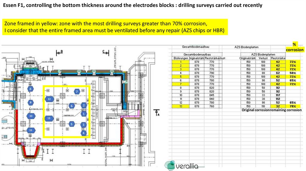
Essen F1, controlling the bottom thickness around the electrodes blocks : drilling surveys carried out recentlyZone framed in yellow: zone with the most drilling surveys greater than 70% corrosion,
I consider that the entire framed area must be ventilated before any repair (AZS chips or HBR)
%
corrosion
Original corrosionremaining corrosion
31.
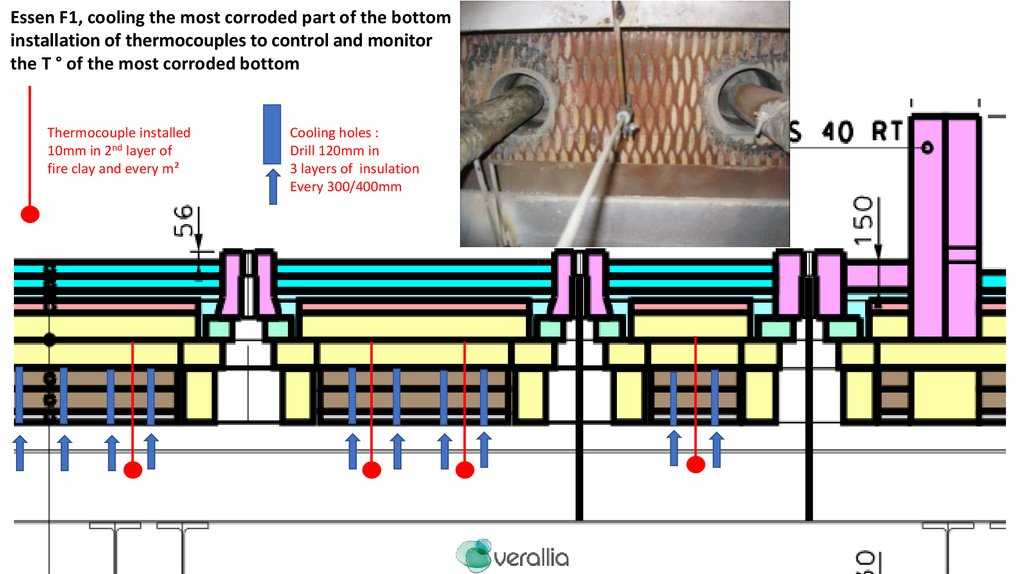
Essen F1, cooling the most corroded part of the bottominstallation of thermocouples to control and monitor
the T ° of the most corroded bottom
Thermocouple installed
10mm in 2nd layer of
fire clay and every m²
Cooling holes :
Drill 120mm in
3 layers of insulation
Every 300/400mm
32.
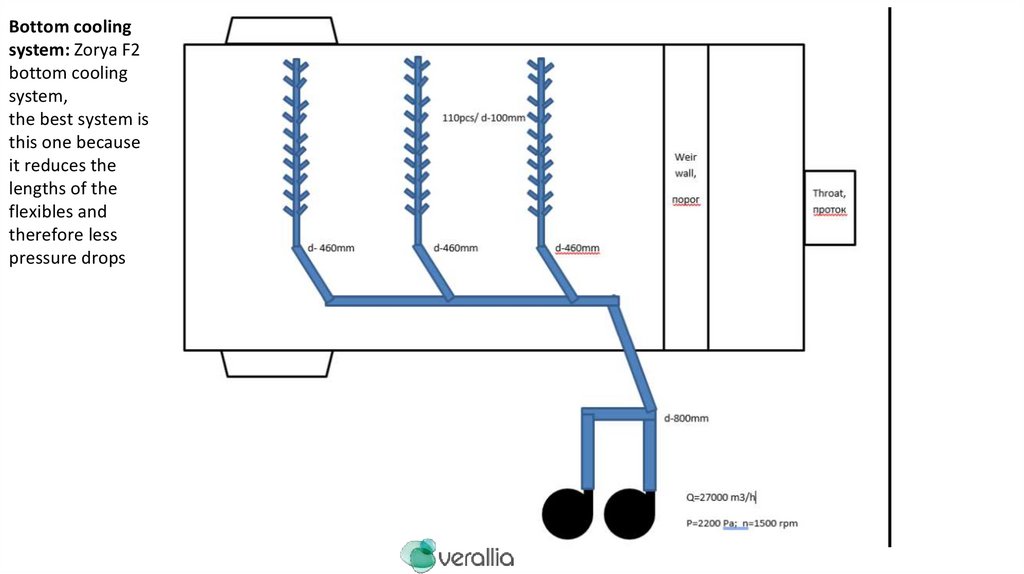
Bottom coolingsystem: Zorya F2
bottom cooling
system,
the best system is
this one because
it reduces the
lengths of the
flexibles and
therefore less
pressure drops
33.
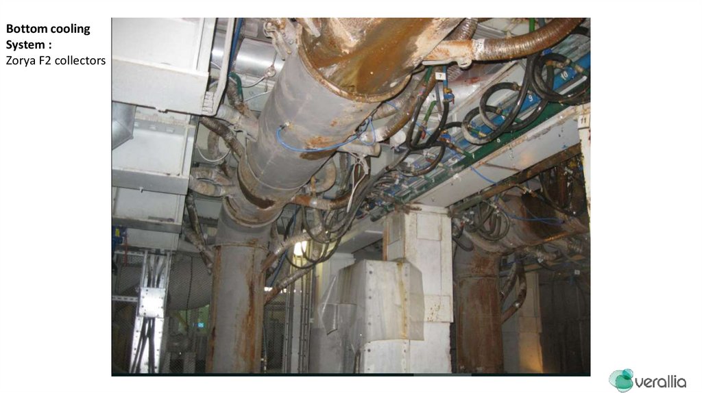
Bottom coolingSystem :
Zorya F2 collectors
34.
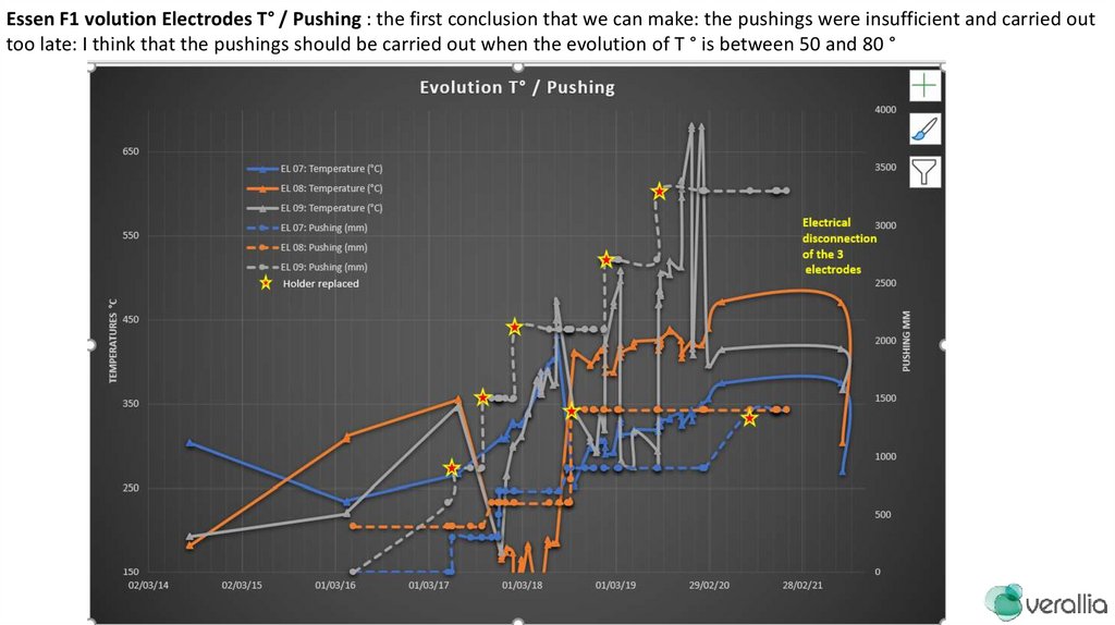
Essen F1 volution Electrodes T° / Pushing : the first conclusion that we can make: the pushings were insufficient and carried outtoo late: I think that the pushings should be carried out when the evolution of T ° is between 50 and 80 °
35.
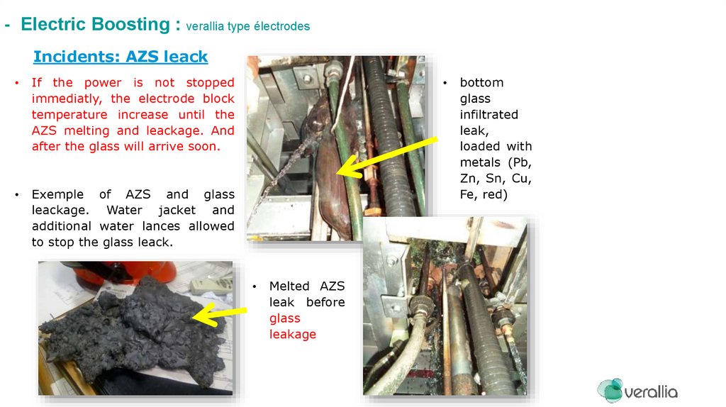
- Electric Boosting : verallia type électrodesIncidents: AZS leack
If the power is not stopped
immediatly, the electrode block
temperature increase until the
AZS melting and leackage. And
after the glass will arrive soon.
Exemple of AZS and glass
leackage. Water jacket and
additional water lances allowed
to stop the glass leack.
Melted AZS
leak before
glass
leakage
bottom
glass
infiltrated
leak,
loaded with
metals (Pb,
Zn, Sn, Cu,
Fe, red)
36.
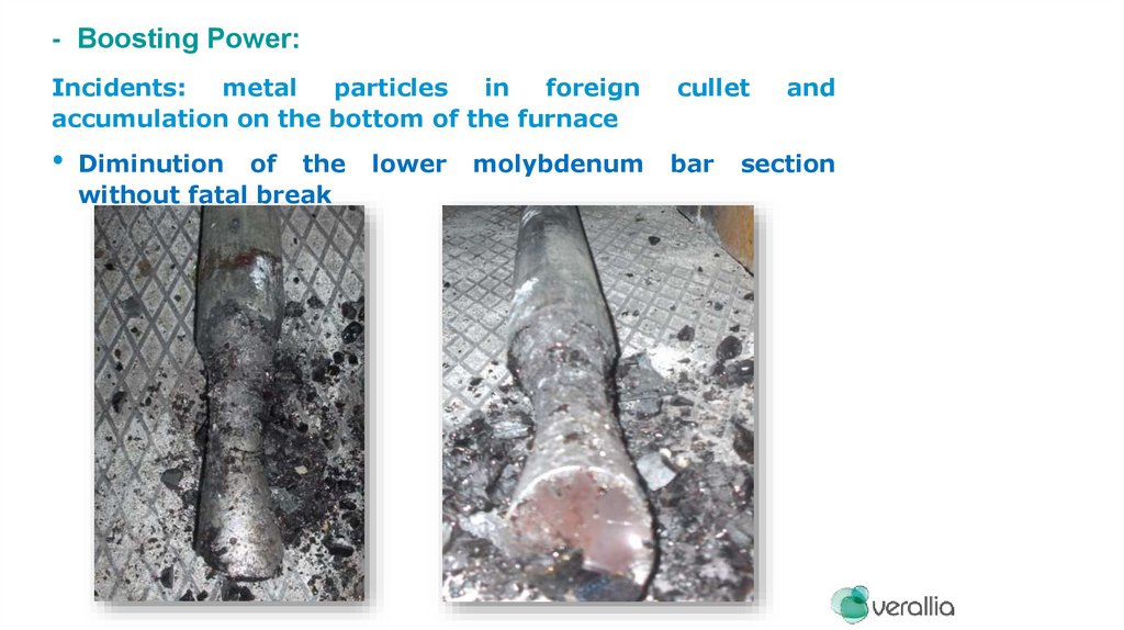
- Boosting Power:Incidents:
metal
particles
in
foreign
accumulation on the bottom of the furnace
cullet
bar
Diminution of the
without fatal break
lower
molybdenum
and
section
37.
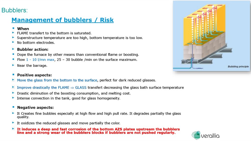
Bubblers:Management of bubblers / Risk
When
FLAME transfert to the bottom is saturated.
Superstructure temperature are too high, bottom temperature is too low.
No bottom electrodes.
Bubbler action:
Dope the furnace by other means than conventional flame or boosting.
Flow 1 - 10 l/mn max, 25 – 30 bubble /min on the surface maximum.
Near the barrage.
Positive aspects:
Move the glass from the bottom to the surface, perfect for dark reduced glasses.
Improve drastically the FLAME GLASS transfert decreasing the glass bath surface temperature
Drastic diminution of the boosting consumption, and melting cost.
Intense convection in the tank, good for glass homogeneity.
Negative aspects:
It Creates fine bubbles especially at high flow and high pull rate. It degrades partially the glass
quality.
It oxidizes the reduced glasses and move partially the color.
It induces a deep and fast corrosion of the bottom AZS plates upstream the bubblers
line and a strong wear of the bubblers blocks if bubblers are not pushed regularly.
38.
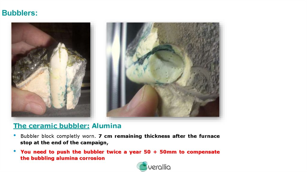
Bubblers:The ceramic bubbler: Alumina
Bubbler block completly worn. 7 cm remaining thickness after the furnace
stop at the end of the campaign,
You need to push the bubbler twice a year 50 + 50mm to compensate
the bubbling alumina corrosion
39.
Furnace Operation & Steering:The operation parameters necessary for a good steering: At stable pull.
Which Furnace Steering Setpoints and Why:
On the superstructure:
Furnace Pressure: By automatic regulation, target 5 Pa. Look at the peep holes on the
opposite side of the flame: flame must be 1/3 inside and 2/3 outside the peep hole, it’s a good
indicator to check fast the situation.
Too Low pressure >> Cold air entrances increase, energy consumption increase.
Too High Pressure >> furnace and regenerators silica superstrucutre degradation,
flames coming out corroding the silica crowns and the walls. Beyond + 10Pa without
being able to go down again, it is absolutely necessary to reduce the pull in order to
reduce the energy and consequently the pressure which must be less than 10Pa
Check the upper tank walls joint (hermetic), to limit air ventilation leaks inside the furnace, that
impacts the furnace pressure in case of bad situation on the checkers and increase the energy
consumption.
Check once by month the fumes pressure along the fumes circuit from the checker base until
the stack. To identify the pluggings or the atmosferic air entrances positions. Operate targeted
cleanings and sealings, in order to keep the furnace pressure in a correct range of value.
40.
Furnace Operation & Steering:The operation parameters necessary for a good steering: At stable pull.
• Which Furnace Steering Setpoints and Why:
Upper and lower
Températures:
Enable to verify if the combustion proceeds normally , and that the flames do not
lengthen, that the combustion inside the furnace is stable and the heat transfert flow to
the batch compostion doesn’t change. It’s a good reference point of the end of
combustion area (at constant power) and it is a good complement to O2 and CO fumes
analysis at the port neck : The target is not to burn inside the checker’s packs in the
regenerators, but to end the combustion inside the furnace.
Measure of the temperature by pyrometer on the port entrance arch key at the end of the
flame time. Allow the compare the temperature with the crown thermocouple indication
and a max temperature (1510°). It’s a safe precaution for silica superstructures and AZS
cruciform checkers that don’t appreciate excess of CO inside the regenerators aswell as
excessive temperatures.
regenerators
and
fumes
circuit
41.
Regenerator Checker Maintenance:1 – Never leave the thickness of sulfates deposites increase under the
rider arches more than the half height between the bootom and the
rider arches key. It favours preferential passages inside the checkers
packs, accelerate the local corrosion and wear with risks of premature
collapses, create pluggings in other cold areas.
2 – Proceed with yearly thermal cleanings, dice the 4th year of
campaign to eliminate dark areas on the light pattern under the checker.
3 – Prefer local thermal cleaning with localized air/gas lances. Prohibite
global thermal cleaning with big burners that lead sometime to dramatic
collapses of the rider arches.
42.
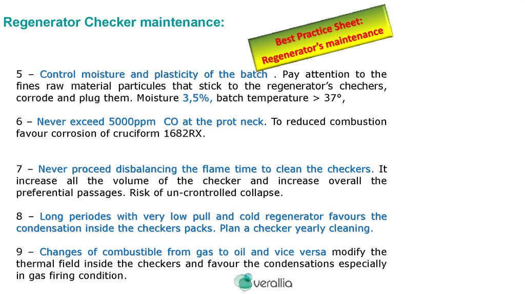
Regenerator Checker maintenance:5 – Control moisture and plasticity of the batch . Pay attention to the
fines raw material particules that stick to the regenerator’s chechers,
corrode and plug them. Moisture 3,5%, batch temperature > 37°,
6 – Never exceed 5000ppm CO at the prot neck. To reduced combustion
favour corrosion of cruciform 1682RX.
7 – Never proceed disbalancing the flame time to clean the checkers. It
increase all the volume of the checker and increase overall the
preferential passages. Risk of un-crontrolled collapse.
8 – Long periodes with very low pull and cold regenerator favours the
condensation inside the checkers packs. Plan a checker yearly cleaning.
9 – Changes of combustible from gas to oil and vice versa modify the
thermal field inside the checkers and favour the condensations especially
in gas firing condition.
43.
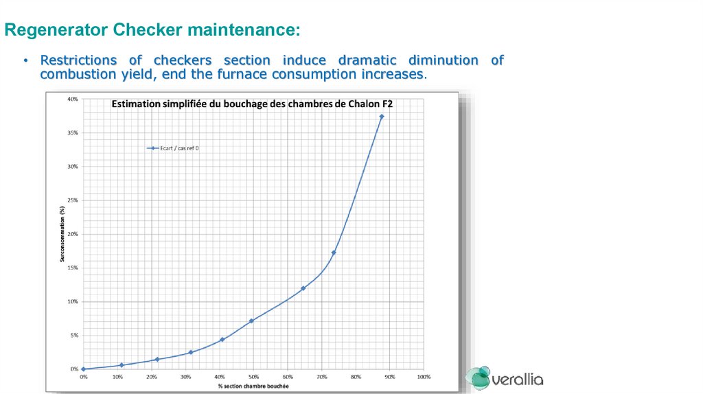
Regenerator Checker maintenance:• Restrictions of checkers section induce dramatic diminution of
combustion yield, end the furnace consumption increases.
44.
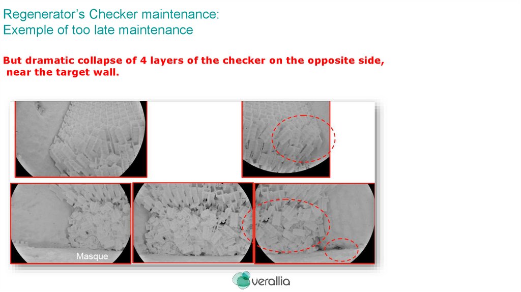
Regenerator’s Checker maintenance:Exemple of too late maintenance
But dramatic collapse of 4 layers of the checker on the opposite side,
near the target wall.