


")


 Промышленность
Похожие презентации:


 behavior")


Welding process
1. Welding process
2.
IntroductionPurposes of this report: - to give an outline of welding processes
Welding is a process of metal joining by applying heat
and sometime pressure
3.
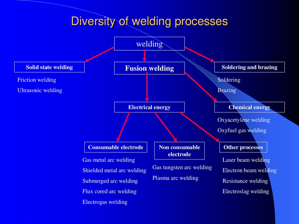
Diversity of welding processeswelding
Solid state welding
Fusion welding
Soldering and brazing
Friction welding
Soldering
Ultrasonic welding
Brazing
Electrical energy
Chemical energy
Oxyacetylene welding
Oxyfuel gas welding
Consumable electrode
Non consumable
electrode
Gas metal arc welding
Shielded metal arc welding
Submerged arc welding
Flux cored arc welding
Electrogas welding
Other processes
Laser beam welding
Gas tungsten arc welding
Plasma arc welding
Electron beam welding
Resistance welding
Electroslag welding
4. Solid state welding
It merges all the welding processes in which there is no fusion of the workpieces .For example, in the solid welding process named resistance seam welding, the
welding join is produced in the wheel electrodes region by applied a current and a
pressure without fusion of the base metal.
The resistance seam welding
(source: Modern Welding (p73))
5. Soldering or brazing
In these processes, only the filler metals which join the two pieces to bewelded are melted and not the base metal. The braze metals have higher
melting temperatures than the solder metals.
Filler metal: brass or solder
Base metal
Characteristics of a brazed or soldered joint
6. Fusion welding
This process involves the partial melting of the two members welded in thejoin region. The thermal energy required for this fusion is usually supplied
by chemical or electrical means.
Base metal melt + filler melt
Characteristics of the fusion weld joint
(Manufacturing Engineering and Technology: p820)
7.
Fusion welding Process8. Topics to Discuss
IntroductionOxyfuel Gas welding
Arc-Welding Processes:Consumable electrode
Electrodes
Arc-Welding Processes:Non Consumable Process
Thermit Welding
Electron Beam Welding
Laser Beam Welding
Cutting
Welding Safety
9. Introduction
Definition : Fusion Welding is defined asmelting together and coalescing
materials by means of heat
Energy is supplied by thermal or
electrical means
Fusion welds made without filler metals
are known as autogenous welds
10. Oxyfuel Gas Welding
Fig : Three basic types of oxyacetylene flames used in oxyfuel-gas welding and cutting operations: (a)neutral flame; (b) oxidizing flame; (c) carburizing, or reducing flame. The gas mixture in (a) is
basically equal volumes of oxygen and acetylene.
11. Oxyfuel Gas Welding
Welding process that uses fuel gas combined with oxygen toproduce flame
This flame heat melts the metals at the joint
Acetylene fuel is used in gas welding process
Primary combustion process
C2H2 + O2
2CO + H2 + heat
This reaction dissociates into carbon monoxide and hydrogen.
Secondary combustion process
2CO + H2 + 1.5 O2
2CO2 + H2O + heat
12. Types of flames
Neutral flameOxidising flame
Carburising flame
Filler Metals :
Additional material to weld the weld zone
Available as rod or wire
They can be used bare or coated with flux
The purpose of the flux is to retard
13. Welding practice & equipment
Welding practice & equipmentSTEPS :
Prepare the edges to be joined and maintain the proper
position
Open the acetylene valve and ignite the gas at tip of
the torch
Hold the torch at about 45deg to the work piece plane
Inner flame near the work piece and filler rod at about
30 – 40 deg
Touch filler rod at the joint and control the movement
according to the flow of the material
14. Torch used in Oxyacetylene Welding
Fig : (a) General view of and(b) cross-section of a
torch used in
oxyacetylene welding.
The acetylene valve is
opened first; the gas is
lit with a park lighter or
a pilot light; then the
oxygen valve is opened
and the flame adjusted.
(c) Basic equipment
used in oxyfuel-gas
welding. To ensure
correct connections, all
threads on acetylene
fittings are left-handed,
whereas those for
oxygen are righthanded. Oxygen
regulators are usually
painted green, acetylene
regulators red.
15. Arc welding process : Consumable electrode
Process goes with the consumable electrode or nonconsumable electrode
Arc produced between the tip of the electrode & work
piece
Arc temperature about 3000 deg
Oldest ,simple & versatile
50 % of industry uses this process
heat generated heats the electrode & immediate area of
the base projected by arc
weld forms when molten metal ,mixture of base metal
and electrode metal and substance from the coating on
the electrode solidifies
electrodes are in the shape of thin,long stick, so the
process is known as stick welding
16. Shielded metal arc welding process
Fig : Schematic illustration of the shielded metal-arcwelding process ( also known as stick welding,
because the electrode is in the shape of a stick).
Fig : Schematic illustration of the shielded metal-arc
welding process. About 50% of all large-scale
industrial welding operations use this process.
17. Submerged arc welding:
Fig : Schematic illustration of the submerged-arc welding process andequipment. The unfused flux is recovered and reused .
18. Submerged arc welding:
Weld arc is shielded by a granular flux ,consisting of silica, lime,manganese oxide, calcium fluoride and other compounds.
Flux is fed into the weld zone by gravity flow through nozzle
Thick layer of flux covers molten metal
Flux acts as a thermal insulator ,promoting deep penetration of heat
into the work piece
Consumable electrode is a coil of bare round wire fed automatically
through a tube
Power is supplied by 3-phase or 2-phase power lines
19. Gas metal arc welding:
GMAW is a metal inert gas welding (MIG)Weld area shielded by an effectively inert atmosphere of
argon,helium,carbon dioxide,various other gas mixtures
Metal can be transferred by 3 methods :
Spray transfer
Globular transfer
Short circuiting
Process capabilities
GMAV process is suitable for welding a variety of ferrous and
non-ferrous metals
Process is versatile ,rapid,economical,welding productivity is
double that of SMAW
20. Gas Metal-Arc Welding
Fig : Schematic illustration of the gas metal-arc welding process,formerly known as MIG (for metal inert gas) welding.
21. Equipment used in Metal-Arc Welding Operations
Fig : Basic equipment used in gas metal-arc welding operations22. Flux–cored Arc – Welding
Flux cored arc welding is similar to a gas metalarc welding
Electrode is tubular in shape and is filled with
flux
Cored electrodes produce more stable arc
improve weld contour and produce better
mechanical properties
Flux is more flexible than others
23. Flux-Cored Arc Welding
Fig : Schematicillustration of the
flux-cored arcwelding process.
This operation is
similar to gas
metal-arc
welding.
24. Electro gas Welding :
EGW is welding the edges of sections vertically in one pass with thepieces placed edge to edge
Weld metal is deposited into weld cavity between the two pieces to be
joined
Mechanical drives moves shoes upwards
Single and multiple electrodes are fed through a conduit and a
continuous arc is maintained using flux-cored electrodes at up to 750 A
Process capabilities :
Weld thickness ranges from 12mm to 75mm
Metals welded are steels, titanium, aluminum alloys
Applications are construction of bridges, pressure vessels, thick walled
and large diameter pipes, storage tanks and ships.
25. Electrogas Welding
Fig : Schematicillustration of the
electrogas welding
process
26. Electroslag Welding:
Similar to Electro gas weldingDifference is Arc is started between electrode tip and bottom part of
the part to be welded
Flux added first and then melted by the heat on the arc
Molten slag reaches the tip of the electrode and the arc is
extinguished
Heat is then continuously produced by electrical resistance of the
molten slag
Single or multiple solid as well as flux-cored electrodes may be used
27. Equipment used in Electroslag welding
Fig : Equipment usedfor electroslag
welding operations.
28.
Solid-State Welding Processes29. Cold Welding
Pressure is applied to theworkpieces through dies or
rolls
Preferably both work pieces
should be ductile
The work pieces should
cleaned thoroughly
Fig: The roll bonding or cladding process
Can not join dissimilar metals
30. Ultrasonic Welding
Surfaces of the twocomponents are
subjected to a static
forces and oscillating
shearing force
Produces a strong,
solid-state bond
Versatile and reliable
for joining metals
Fig: a) Components of an ultrasonic welding machine
for lap welds.The lateral vibration of the tool tip
cause plastic deformation and bonding at the
interface of the work piece b)Ultrasonic some
welding using a roller c)An ultrasonically welded
part
31. Friction Welding
Developed in the 1940’sParts are circular in shape
Can be used to join a wide variety of materials
Fig: Sequence of operation in the friction welding process 1)Left-hand component is rotated at high speed. 2)
Right-hand component is brought into contact under an axial force 3)Axial force is increased;the flash begins to
form 4) Left-hand component stops rotating;weld is completed.The flash can subsequently be removed by
machining or grinding
32. Friction Welding
Process can be fully automatedCan weld solid steel bars up to 250mm in outside diameter
Fig:Shape of friction zone in friction welding,as a function of the force applied and the rotational speed
33. Inertia Friction Welding
Modification of Friction WeldingEnergy is supplied by a fly wheel
The parts are pressed together by a normal force
As friction at the interface increases, the fly wheel slows down
The weld is completed when the flywheel stops
Fig : The principle of the friction stir welding
process. Aluminum-alloy plates up to 75mm
(3in) thick have been welded by this process
34. Linear Friction Welding
Parts are joined by a linear reciprocating motionParts do not have to be circular or tubular
In this application, one part is moved across the face of the
other part using a balanced reciprocating mechanism
35. Friction Stir Welding (FSW)
New Process for welding aerospace metalsResearch is being directed towards using this
process for polymers
FSW uses a 3rd nonconsumable tool inserted
between the two bodies to heat the material to be
joined
36. Resistance Welding
Developed in the early 1900’sA process in which the heat required for welding is
produced by means of electrical resistance across the two
components
RW does not requiring the following:
– Consumable electrodes
– Shield gases
– Flux
37. Resistance Spot Welding
RSW uses the tips of two opposing solid cylindrical electrodesPressure is applied to the lap joint until the current is turned off in
order to obtain a strong weld
Fig: (a) Sequence in the resistance spot welding
38. Resistance Spot Welding
Surfaces should be cleanAccurate control of and timing of electric current and of pressure are
essential in resistance welding
Fig: b)Cross-section of a spot weld,showing
the weld nugget and the indentation of
the electrode on the sheet surfaces.This
is one of the most commonly used
process in sheet-metal fabrication and in
automotive-body assembly
39. Resistance Seam Welding
RSEM is modification of spot welding wherein the electrodes are replaced byrotating wheels or rollers
The electrically conducting rollers produce a spot weld
RSEM can produce a continuous seam & joint that is liquid and gas tight
Fig : (a) Seam-Welding Process in which rotating rolls act as electrode (b)
Overlapping spots in a seam weld. (c) Roll spot weld (d) Resistance-welded gasoline tank
40. Resistance Projection Welding
RPW is developed byintroducing high
electrical resistance at
a joint by embossing
one or more
projections on the
surface to be welded
Weld nuggets are
similar to spot welding
Fig: a) Resistance projection Welding b)A welded bracket c) &
d) Projection welding of nuts r threaded hosses and stack
41. Resistance Projection Welding
The electrodes exert pressure to compress theprojections
Nuts and bolts can be welded to sheet and plate
by this process
Metal baskets, oven grills, and shopping carts
can be made by RPW
42. Flash Welding
Heat is generated from the arc as the ends as the two members contactsAn axial force is applied at a controlled rate
Weld is formed in plastic deformation
Fig : (a)Flash-welding process for end-to –end welding of solid rods or tubular parts
(b) & (c) Typical parts made by flash welding (d)Design Guidelines for flash welding
43. Stud Welding
Small part or a threaded rod or hanger serves as a electrodeAlso called as Stud arc welding
Prevent oxidation to concentrate the heat generation
Portable stud-welding is also available
Fig:The sequence of operation in stud welding,which is used for welding bars threaded rods and
various fasteners onto metal plates