


 Электроника
Похожие презентации:


User Manual
1.
A4 SeriesUser Manual
2.
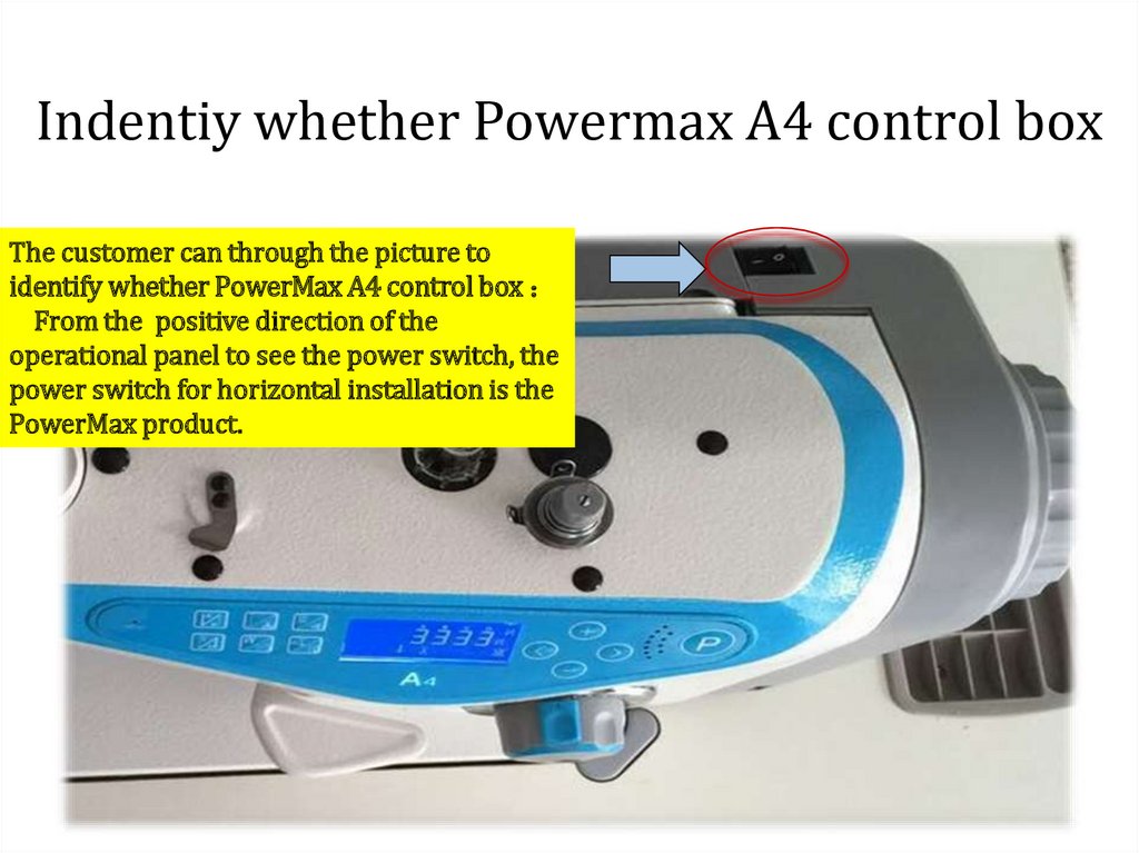
Indentiy whether Powermax A4 control boxThe customer can through the picture to
identify whether PowerMax A4 control box
From the positive direction of the
operational panel to see the power switch, the
power switch for horizontal installation is the
PowerMax product.
3.
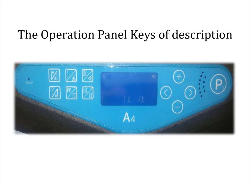
The Operation Panel Keys of description4.
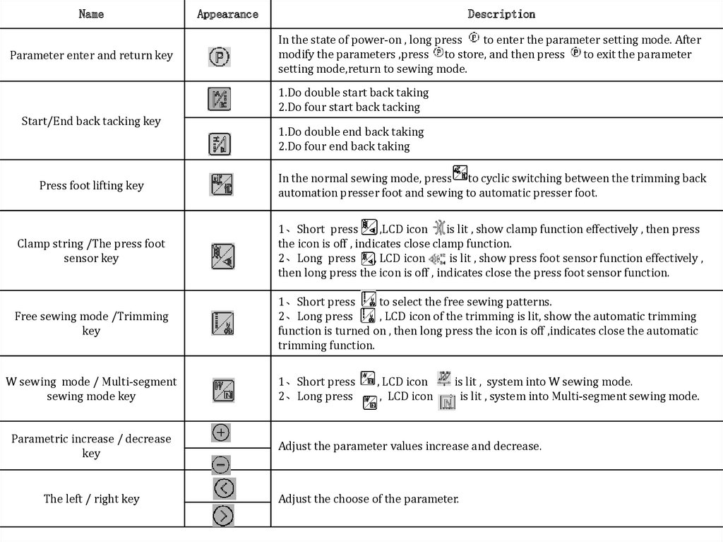
NameParameter enter and return key
Appearance
Description
In the state of power-on , long press
to enter the parameter setting mode. After
modify the parameters ,press to store, and then press
to exit the parameter
setting mode,return to sewing mode.
1.Do double start back taking
2.Do four start back tacking
Start/End back tacking key
1.Do double end back taking
2.Do four end back taking
Press foot lifting key
In the normal sewing mode, press to cyclic switching between the trimming back
automation presser foot and sewing to automatic presser foot.
Clamp string /The press foot
sensor key
1、Short press
,LCD icon
is lit , show clamp function effectively , then press
the icon is off , indicates close clamp function.
2、Long press
, LCD icon
is lit , show press foot sensor function effectively ,
then long press the icon is off , indicates close the press foot sensor function.
Free sewing mode /Trimming
key
1、Short press
to select the free sewing patterns.
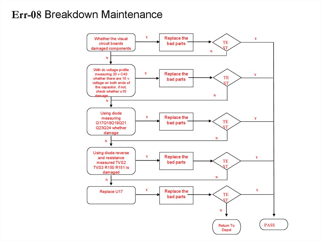
2、Long press
, LCD icon of the trimming is lit, show the automatic trimming
function is turned on , then long press the icon is off ,indicates close the automatic
trimming function.
W sewing mode / Multi-segment
sewing mode key
Parametric increase / decrease
key
The left / right key
1、Short press
2、Long press
, LCD icon
, LCD icon
is lit , system into W sewing mode.
is lit , system into Multi-segment sewing mode.
Adjust the parameter values increase and decrease.
Adjust the choose of the parameter.
5.
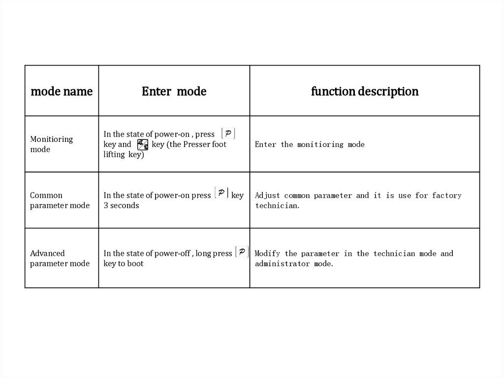
mode nameEnter mode
function description
Monitioring
mode
In the state of power-on , press
key and
key (the Presser foot
lifting key)
Common
parameter mode
In the state of power-on press
3 seconds
Advanced
parameter mode
In the state of power-off , long press
key to boot
Enter the monitioring mode
key
Adjust common parameter and it is use for factory
technician.
Modify the parameter in the technician mode and
administrator mode.
6.
Motor Introduction7.
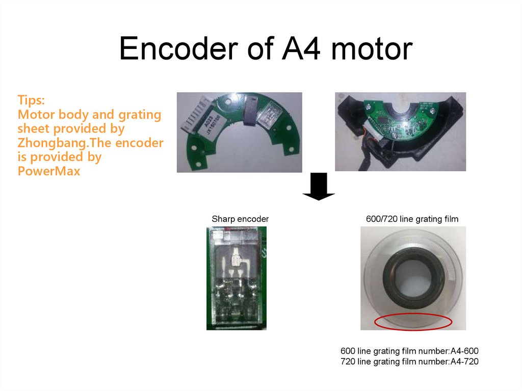
Encoder of A4 motorTips:
Motor body and grating
sheet provided by
Zhongbang.The encoder
is provided by
PowerMax
Sharp encoder
600/720 line grating film
600 line grating film number:A4-600
720 line grating film number:A4-720
8.
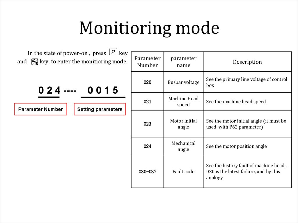
Monitioring modeIn the state of power-on , press
key
and
key. to enter the monitioring mode.
0 2 4 ---Parameter Number
Parameter
Number
parameter
name
Description
020
Busbar voltage
See the primary line voltage of control
box
021
Machine Head
speed
See the machine head speed
023
Motor initial
angle
See the motor initial angle (it must be
used with P62 parameter)
024
Mechanical
angle
See the motor position angle
030-037
Fault code
See the history fault of machine head ,
030 is the latest failure, and by this
analogy.
0015
Setting parameters
9.
Common mode parametersSpeed parameter adjustment
Speed locking
Restore Factory
Upper stop position adjust
A key to save the parameter setting
Constant sewing function setting
Motor initial angle measurement
language selection
10.
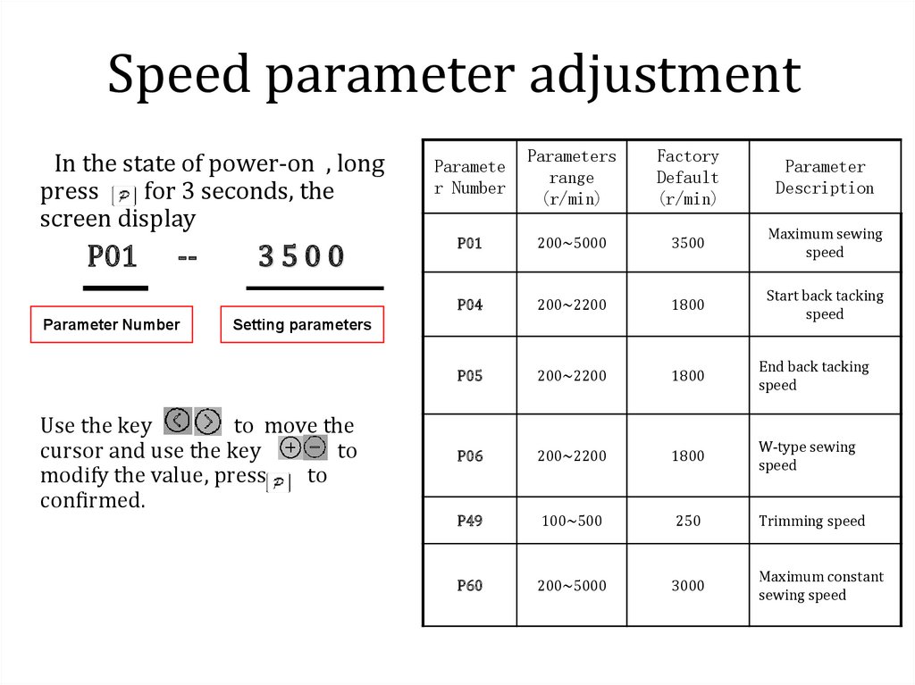
Speed parameter adjustmentIn the state of power-on , long
press
for 3 seconds, the
screen display
P01
--
Parameter Number
3500
Paramete
r Number
Parameters
range
(r/min)
Factory
Default
(r/min)
Parameter
Description
P01
200~5000
3500
Maximum sewing
speed
P04
200~2200
1800
Start back tacking
speed
P05
200~2200
1800
End back tacking
speed
P06
200~2200
1800
W-type sewing
speed
P49
100~500
250
Trimming speed
P60
200~5000
3000
Maximum constant
sewing speed
Setting parameters
Use the key
to move the
cursor and use the key
to
modify the value, press
to
confirmed.
11.
Lock speed settingIn the state of power-on ,long
press
for 3 seconds to enter
the parameter adjustment .
P68 -P68 parameter
is the maximum
lock speed
0000
Setting the maximum lock
speed
After setting press
take effect
to confirm, re-switch
Parameter
Number
Parameter
Range
Factory
Default
Parameter
Description
P68
0~5000
3500
The
maximum
speed lock
12.
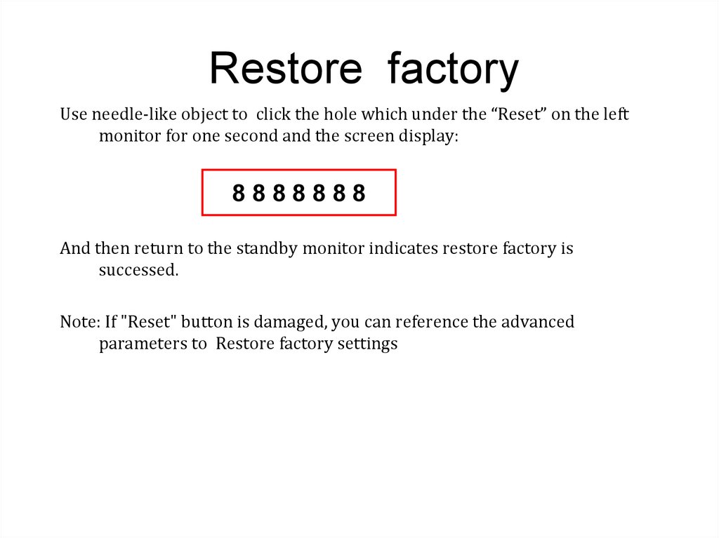
Restore factoryUse needle-like object to click the hole which under the “Reset” on the left
monitor for one second and the screen display:
8888888
And then return to the standby monitor indicates restore factory is
successed.
Note: If "Reset" button is damaged, you can reference the advanced
parameters to Restore factory settings
13.
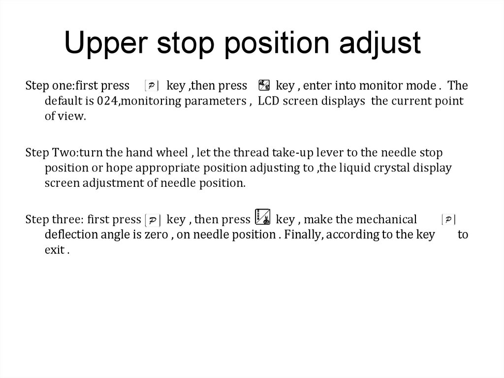
Upper stop position adjustStep one:first press
key ,then press
key , enter into monitor mode . The
default is 024,monitoring parameters , LCD screen displays the current point
of view.
Step Two:turn the hand wheel , let the thread take-up lever to the needle stop
position or hope appropriate position adjusting to ,the liquid crystal display
screen adjustment of needle position.
Step three: first press
key , then press
key , make the mechanical
deflection angle is zero , on needle position . Finally, according to the key
exit .
to
14.
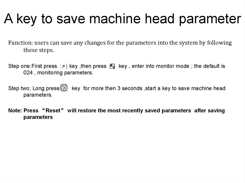
A key to save machine head parameterFunction: users can save any changes for the parameters into the system by following
these steps.
Step one:First press
key ,then press
024 , monitoring parameters.
Step two; Long press
parameters.
key , enter into monitor mode ; the default is
key for more then 3 seconds ,start a key to save machine head
Note: Press “Reset” will restore the most recently saved parameters after saving
parameters
15.
Constant sewing function settingFunction: fixed-length slit open after the trigger function, touch the pedal is automatically set in
accordance with the fixed length of the complete stitch sewing process parameters, the process is
not completed before the middle of the parking impact
Step:
Step one: long key
three seconds, the screen shows P01-01-16 set the total number of multi-seam section
P01
The total number
of segments set
-
01
-
16
Each pin
number
Number of
segments
Step Two: Press the panel button
after setting the top right corner of the screen
display
, shows the trigger function to play。
Step Three: After a light step on the foot controller automatically complete fixed slit
16.
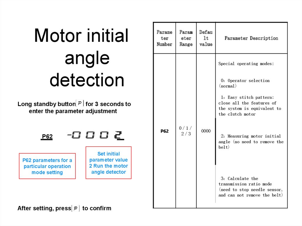
Motor initialangle
detection
Parame
ter
Number
Param
eter
Range
Defau
lt
value
Special operating modes:
0 Operator selection
(normal)
1 Easy stitch pattern:
close all the features of
the system is equivalent to
the clutch motor
Long standby button
for 3 seconds to
enter the parameter adjustment
P62
P62
P62 parameters for a
particular operation
mode setting
Parameter Description
0 1
2 3
0000
2 Measuring motor initial
angle (no need to remove the
belt)
Set initial
parameter value
2 Run the motor
angle detector
3 Calculate the
transmission ratio mode
(need to stop needle sensor,
and can not remove the belt)
After setting, press
to confirm
17.
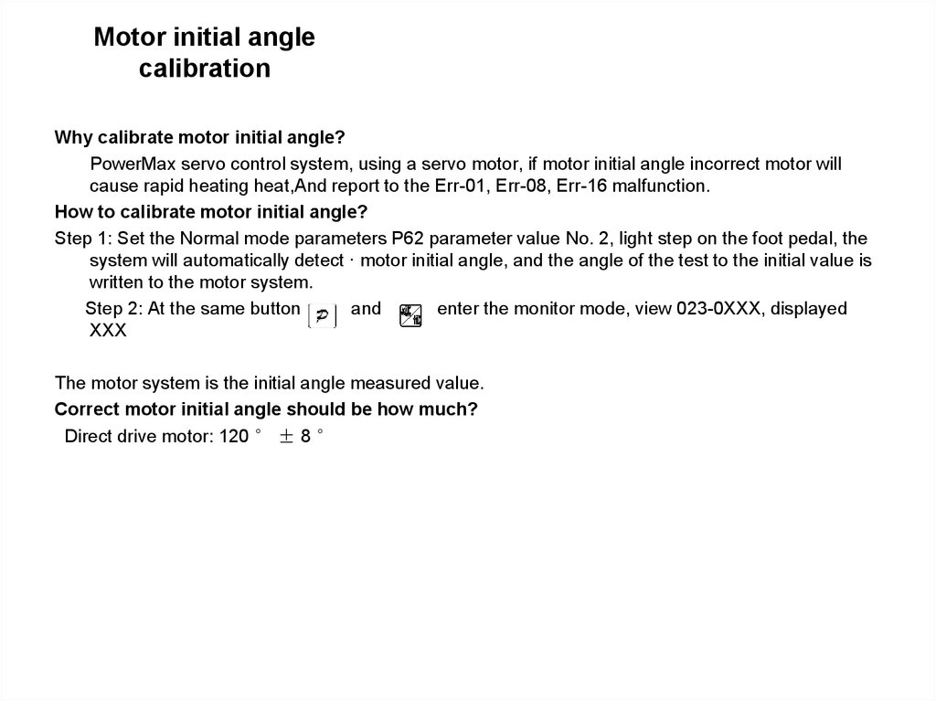
Motor initial anglecalibration
Why calibrate motor initial angle?
PowerMax servo control system, using a servo motor, if motor initial angle incorrect motor will
cause rapid heating heat,And report to the Err-01, Err-08, Err-16 malfunction.
How to calibrate motor initial angle?
Step 1: Set the Normal mode parameters P62 parameter value No. 2, light step on the foot pedal, the
system will automatically detect · motor initial angle, and the angle of the test to the initial value is
written to the motor system.
Step 2: At the same button
and
enter the monitor mode, view 023-0XXX, displayed
XXX
The motor system is the initial angle measured value.
Correct motor initial angle should be how much?
Direct drive motor: 120 ° ± 8 °
18.
languageselection
Paramet
er
Number
Paramete
r Range
Defaul
t
value
Parameter Description
Long standby button
for 3 seconds to
enter the parameter setting
P99 ----- 0001
0000 shut down
P99
P99 parameter
selection
parameters for
the language
After setting, press
Language
according to
their needs
to confirm
0/1/2
1
0001 Chines
0002 English
19.
Advanced parameter setting• Acceleration
sensitivity setting
• Pedal response
control settings
• reset
20.
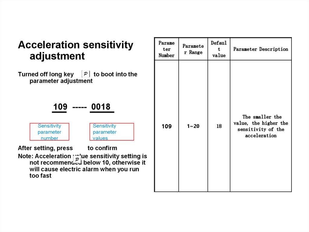
Acceleration sensitivityadjustment
Parame
ter
Number
Paramete
r Range
Defaul
t
value
Parameter Description
18
The smaller the
value, the higher the
sensitivity of the
acceleration
Turned off long key
to boot into the
parameter adjustment
109 ----- 0018
Sensitivity
parameter
number
Sensitivity
parameter
values
After setting, press
to confirm
Note: Acceleration value sensitivity setting is
not recommended below 10, otherwise it
will cause electric alarm when you run
too fast
109
1~20
21.
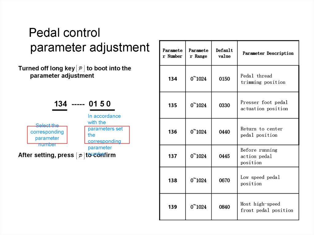
Pedal controlparameter adjustment
Turned off long key
to boot into the
parameter adjustment
134 ----- 01 5 0
Select the
corresponding
parameter
number
After setting, press
In accordance
with the
parameters set
the
corresponding
parameter
number
to
confirm
Paramete
r Number
Paramete
r Range
Default
value
134
0~1024
0150
Pedal thread
trimming position
135
0~1024
0330
Presser foot pedal
actuation position
136
0~1024
0440
Return to center
pedal position
Parameter Description
137
0~1024
0445
Before running
action pedal
position
138
0~1024
0670
Low speed pedal
position
139
0~1024
0840
Most high-speed
front pedal position
22.
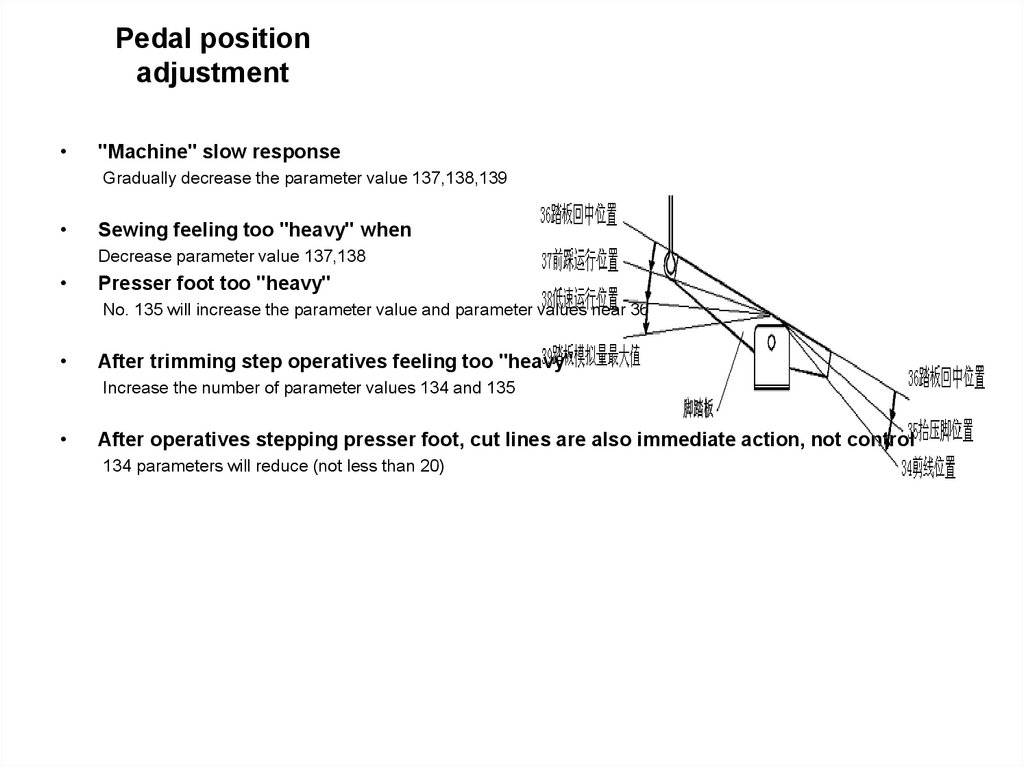
Pedal positionadjustment
"Machine" slow response
Gradually decrease the parameter value 137,138,139
Sewing feeling too "heavy" when
Decrease parameter value 137,138
Presser foot too "heavy"
No. 135 will increase the parameter value and parameter values near 36
After trimming step operatives feeling too "heavy"
Increase the number of parameter values 134 and 135
After operatives stepping presser foot, cut lines are also immediate action, not control
134 parameters will reduce (not less than 20)
23.
Pedal positionadjustment
When adjusting the parameters of what should pay attention to the pedal
When adjusting the pedal parameters should be set in accordance with the following rules
Parameter value 134 <value 135 <value 136 parameter values <137 parameter value <138 parameter
value <139
If I do not follow the rules set what would happen, how to solve
If you do not follow the rules set, there may be no cut line, presser foot or low case after you press the pedal
sewing machine. Then please restore the factory settings.
24.
Restore the factoryTurned off until the power button
long to enter the parameter setting
interface, adjusted to
162
162
parameters to
restore
factory
settings
–
0002
0002 to
restore
factory value
After completion of the setting press
key
three seconds after reverse
stitching restore factory
Note: This feature is under "Reset" button
in case of damage
25.
Fault code• Err-01 (Hardware overcurrent
• Err-03 (System Brown
• Err-04 (When parking
overvoltage)
• Err-05 (Run-time overvoltage)
• Err-07 (Current detection fault)
• Err-08 (Motor stall)
• Err-09 (Brake circuit fault)
• Err-10 (Communication
breakdown)
• Err-13 (Motor fault HALL)
• Err-15(Overspeed fault)
• Err-16 (Motor reverse
fault)
• Err-18 (Motor overload)
• Err-23 (Motor stall
• UP fault Total lift switch
failure
26.
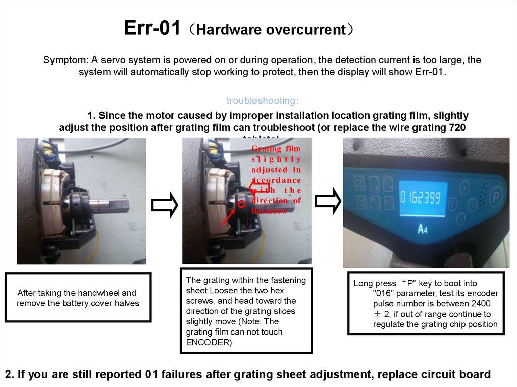
Err-01 Hardware overcurrentSymptom: A servo system is powered on or during operation, the detection current is too large, the
system will automatically stop working to protect, then the display will show Err-01.
troubleshooting:
1. Since the motor caused by improper installation location grating film, slightly
adjust the position after grating film can troubleshoot (or replace the wire grating 720
tablets).
Grating film
slightly
adjusted in
acco rd an ce
with the
direction of
the arrow
After taking the handwheel and
remove the battery cover halves
The grating within the fastening
sheet Loosen the two hex
screws, and head toward the
direction of the grating slices
slightly move (Note: The
grating film can not touch
ENCODER)
Long press “P" key to boot into
"016" parameter, test its encoder
pulse number is between 2400
± 2, if out of range continue to
regulate the grating chip position
2. If you are still reported 01 failures after grating sheet adjustment, replace circuit board
27.
Err-03 System BrownSymptom: A servo system detects if the input voltage is below the normal operating
voltage, the system will automatically stop working to protect the operating panel
displays Err-03 at startup.
troubleshooting:
1. City network voltage is too low
With a multimeter to check the power supply voltage is less
than 220V ± 20%. If the voltage is too low recommendations to
improve the grid voltage.
2. System board component damage
If the grid voltage is normal, it is a system board components
are damaged, replace the system board.
28.
Err-04 When parking overvoltageFault description: detects when the servo system is turned on input voltage is higher than
the normal operating voltage, the system will automatically stop working to protect,
then the panel will show Err-04.
troubleshooting:
1. Check the City Network Voltage
With a multimeter to check the power supply voltage is higher than 220V ± 20%,
if the voltage is too high recommendations to improve the grid voltage.
2. System board component damage
If the grid voltage is normal, it is a system board components are damaged,
replace the system board。
29.
Err-05 Run-time overvoltageErr-09 Brake circuit fault
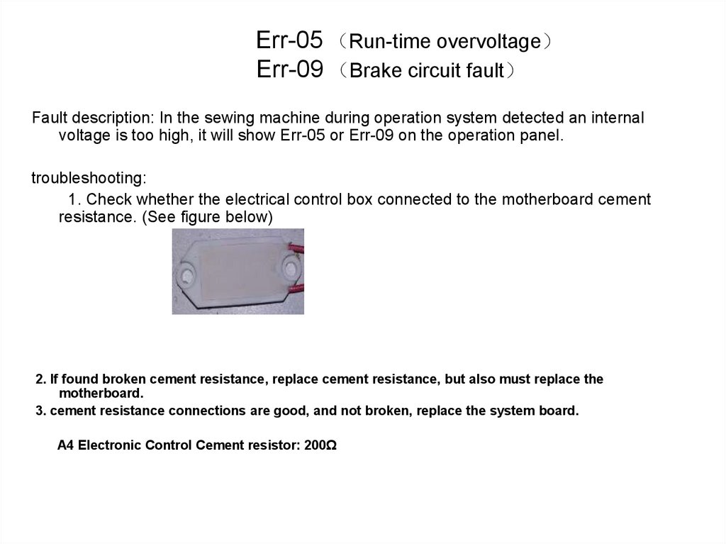
Fault description: In the sewing machine during operation system detected an internal
voltage is too high, it will show Err-05 or Err-09 on the operation panel.
troubleshooting:
1. Check whether the electrical control box connected to the motherboard cement
resistance. (See figure below)
2. If found broken cement resistance, replace cement resistance, but also must replace the
motherboard.
3. cement resistance connections are good, and not broken, replace the system board.
A4 Electronic Control Cement resistor: 200Ω
30.
Err-07 Current detection circuit faultFailure Description: The system detects when the machine is switched on or
run to the circuit board current sensor is damaged, Err-07 will be displayed
on the operator panel.
troubleshooting:
Replace the electric control box board.
31.
Err-08/ Err-23 Motor stallFault description: In the motor is driven, the system does not detect motor rotation or exceed its load capacity, it will
show Err-08 or Err-23 on the operation panel
troubleshooting:
1. turn on the power, they reported 08
A Check that the motor is dead foreign body stuck.
B according to Err-01 troubleshooting check sheet position raster
2. Restore factory restore factory settings as
3. Daily 08 during sewing
A test motor initial angle (refer to detect motor initial angle method)
B according to Err-01 troubleshooting check sheet position raster
4. If the above method does not resolve, replace the PCB
32.
Err-10 Communication breakdownSymptom: A communication system detected between the
control board and the operator panel is not normal, A4
operator panel displays Err-10.
troubleshooting:
Respectively replacement operation panel or circuit
board
33.
Err-13 motor HALL faultFailure Description: The system detects the motor encoder signal is not
synchronized with the sensor signal, the operation panel displays
Err-13.
troubleshooting:
1. Check the motor and the electronic control of the connection
socket is connected.
2. The motor encoder is damaged, replace encoder.
34.
Err-15 Overspeed faultErr-16 Motor reverse fault
Failure Description: The system detects the motor exceeds the set
value range or the occurrence of the reverse direction, the operator
panel displays Err-15 or Err-16 during operation.
troubleshooting:
1. Test motor initial angle
2. Replace the motor encoder.
35.
Err-18 Motor overloadFailure Description: The system detects motor load is too large, the operation panel
displays Err-18.
troubleshooting:
1. Test motor initial angle
2. Insert the needle position slightly elevated, or changing the trimming cam time
Trimming it slightly longer time
36.
Failure Description: The turn table switch defective Cause This error alarms.Troubleshooting:
1. Power status under long key P to enter the parameter setting
2. Set the parameter to "P66", the screen displays "P66-0002" change it to
"P66-0000".
3. Press the P button to confirm.
37.
No error Troubleshooting38.
Ⅰ. Depress the foot pedal and the motor without any response, whilenot being given the operation panel display
troubleshooting:
1. Check the pedal connected to the
control box is good
2. Replace the pedal.
39.
II. Pedal sewing machine no high-speed,error-free operation panel and display
troubleshooting:
1. Check speed parameter setting is
being modified
2. Replace the pedal.
40.
III. Display no displaytroubleshooting:
A first determine whether it is caused by
damage to the display, please replace the
display case
B as the display normal, replace circuit
board
41.
Circuit board repair42.
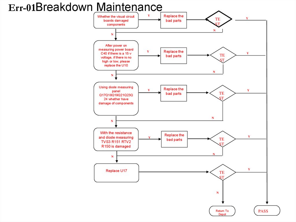
Err-01Breakdown MaintenanceWhether the visual circuit
boards damaged
components
Y
Replace the
bad parts
TE
ST
Y
N
N
After power on
measuring power board
C40 if there is a 15 v
voltage, if there is no
high or low, please
replace the U10
Y
Replace the
bad parts
TE
ST
Y
N
N
Using diode measuring
panel
Q17Q18Q19Q21Q23Q
24 whether have
damage of components
Y
Replace the
bad parts
Y
TE
ST
N
N
With the resistance
and diode measuring
TVS3 R151 RTV2
R150 is damaged
N
Y
Replace the
bad parts
TE
ST
Y
N
Y
Replace U17
TE
ST
N
Return To
Depot
PASS
43.
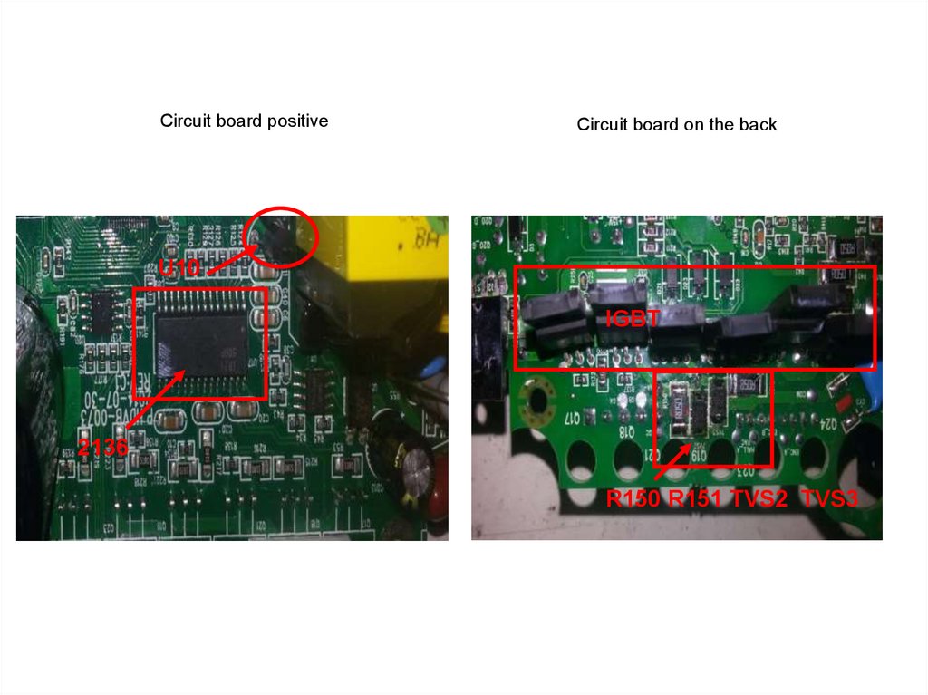
Circuit board positiveCircuit board on the back
U10
IGBT
2136
R150 R151 TVS2 TVS3
44.
Err-08 Breakdown MaintenanceWhether the visual
circuit boards
damaged components
Y
Replace the
bad parts
Y
TE
ST
N
N
With dc voltage profile
measuring 20 v C40
whether there are 15 v
voltage on both ends of
the capacitor, if not,
check whether u10
damage
Y
Replace the
bad parts
TE
ST
Y
N
N
Using diode
measuring
Q17Q18Q19Q21
Q23Q24 whether
damage
Y
Replace the
bad parts
Y
TE
ST
N
N
Using diode reverse
and resistance
measured TVS2
TVS3 R150 R151 is
damaged
Y
Replace the
bad parts
N
N
Replace U17
Y
TE
ST
Y
Y
Replace the
bad parts
TE
ST
N
Return To
Depot
PASS
45.
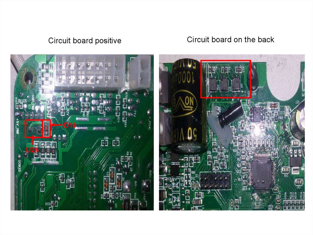
Circuit board positiveCircuit board on the back
U10
IGBT
2136
R150 R151 TVS2 TVS3
46.
Err-10 Breakdown MaintenanceWhether the visual
circuit boards
damaged components
Y
Replace
the bad
parts
TE
ST
Y
N
N
Voltage shift gears
was used to measure
the power plate U24
foot 1 and 2 feet 5 v
voltage output, U24
without replacement
Y
Replace
the bad
parts
TE
ST
Replace
the bad
parts
TE
ST
Y
N
Using diode
measuring panel D16
is damaged
Y
N
N
Measuring R57 R82
resistance is normal
Y
Y
Replace
the bad
parts
TE
ST
Y
N
Y
Replace U3 U11
TE
ST
N
Return
To Depot
PASS
47.
Circuit board positive1
U24
D16
Circuit board on the back
48.
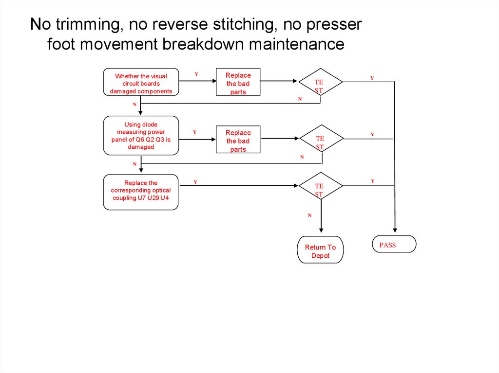
No trimming, no reverse stitching, no presserfoot movement breakdown maintenance
Whether the visual
circuit boards
damaged components
Y
Replace
the bad
parts
TE
ST
Y
N
N
Using diode
measuring power
panel of Q6 Q2 Q3 is
damaged
Y
Replace
the bad
parts
TE
ST
Y
N
N
Replace the
corresponding optical
coupling U7 U29 U4
Y
TE
ST
Y
N
Return To
Depot
PASS
49.
U29U7 U4
Reverse stitching
controlQ2
Shear line
controlQ6
Presser foot
controlQ3