


 Электроника
Похожие презентации:


")

")


 Wireless Audio - Soundbar ’2017 SAMSUNG ELECTRONICS CO.,LTD. VD R&D GROUP")

Development of air conditioning
1.
EDUCATION MANUAL- 06R INVERTER RAC -
2006.05
System Appliances Division
Air Conditioning R&D Team
Inverter TF
2.
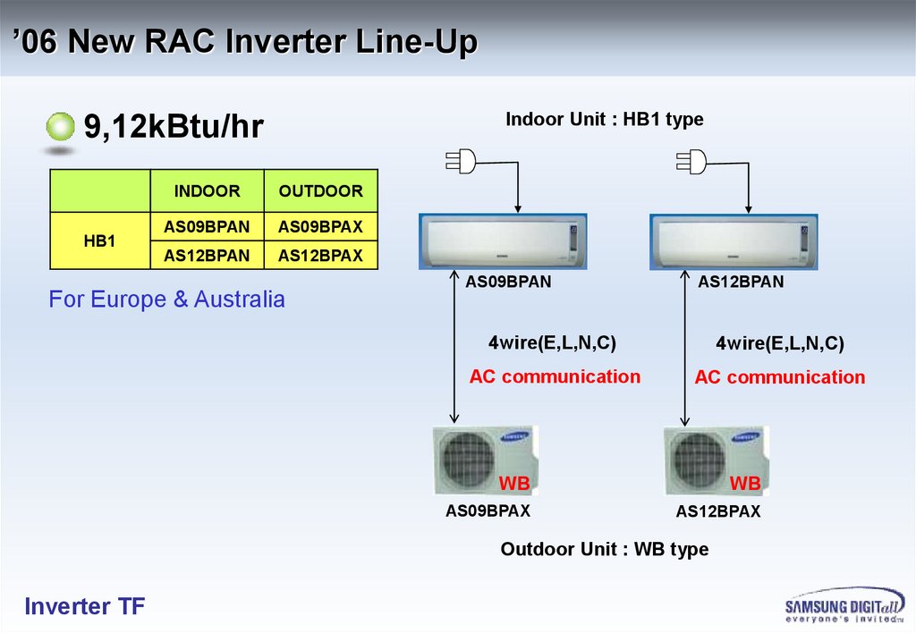
’06 New RAC Inverter Line-UpIndoor Unit : HB1 type
9,12kBtu/hr
HB1
INDOOR
OUTDOOR
AS09BPAN
AS09BPAX
AS12BPAN
AS12BPAX
For Europe & Australia
AS09BPAN
AS12BPAN
4wire(E,L,N,C)
4wire(E,L,N,C)
AC communication
AC communication
WB
WB
AS09BPAX
AS12BPAX
Outdoor Unit : WB type
Inverter TF
3.
’06 New RAC Inverter Line-UpIndoor Unit : WW1 Premium type
9,12kBtu/hr
WW1
AQB09JJWC/KCV
INDOOR
OUTDOOR
AQB09JJWC
UQB09JJWC
AQB12JJWC
UQB12JJWC
For United States
3wire (E,L,N)
3wire (E,L,N)
+ 2Wire(F1,F2)
+ 2Wire(F1,F2)
485 communication
485 communication
WB
UQB09JJWC/KCV
Inverter TF
AQB12JJWC/KCV
WB
UQB12JJWC/KCV
4.
’06 New RAC Inverter Line-Up18,24kBtu/hr
HB2
G3_P
WW2
INDOOR
OUTDOOR
AS18BPAN
AS18BPAX
AS24BPAN
AS24BPAX
SH18BP6
SH18BP6X
SH24BP2
SH24BP2X
SH18BW6
SH18BW6X
SH24BW2
SH24BW2X
AS18BPAN
AS24BPAN
SH18BP6
SH24BP2
SH18BW6
SH24BW2
3wire (E,L,N)
+ 2Wire(F1,F2)
485 communication
3wire (E,L,N)
+ 2Wire(F1,F2)
485 communication
For Europe & Australia
Q
P
AS18BPAX
SH18BP6X
SH18BW6X
Inverter TF
AS24BPAX
SH24BP2X
SH24BW2X
5.
’06 New RAC Inverter Line-UpIndoor Unit : WW2 Premium type
18,24kBtu/hr
WW2
AQB18J6WC/KCV
INDOOR
OUTDOOR
AQB18J6WC
UQB18J6WC
AQB24J2WC
UQB24J2WC
For United States
AQB24J2WC/KCV
3wire (E,L,N)
3wire (E,L,N)
+ 2Wire(F1,F2)
+ 2Wire(F1,F2)
485 communication
485 communication
Q
P
UQB18J6WC/KCV
UQB24J2WC/KCV
Inverter TF
6.
Comparison of Inverter Line-UpDaikin:●, Mitsubishi:●, Samsung ’06:
Capacity
9kBtu/hr
12kBtu/hr
18kBtu/hr
24kBtu/hr
Wall mounted
(RAC)
●●
●●
●●
●●
Europe
HB1
G2-P
WW1
HB1
G2-P
WW1
HB2
G3-P
WW2
HB2
G3-P
WW2
Australia
HB1
G2-P
HB1
G2-P
-
HB2
G3-P
US
WW1
WW1
WW2
WW2
China
HB1
G2-P
WW1
China Deluxe
HB1
G2-P
WW1
China Deluxe
-
-
SAMSUNG
Model
Type
Inverter TF
7.
FEATURES - High Energy EfficiencyEnergy Grade
Sales Area
Capacity
Model Name
Remarks
Cooling
Heating
9kBtu/hr
AS09BPAN
A
A
A/A
12kBtu/hr
AS12BPAN
A
A
A/A
AS18BPAN
A
B
-
SH18BP6
A
B
-
SH18BW6
A
B
-
AS24BPAN
B
D
-
SH24BP2
B
D
-
SH24BW2
B
D
-
9kBtu/hr
AS09BPAN
6.0 ★
5.0 ★
TESAW 2006
12kBtu/hr
AS12BPAN
5.0 ★
4.0 ★
TESAW 2006
24kBtu/hr
AS24BPAN
3.5 ★
2.0 ★
-
9kBtu/hr
AQB09JJWC
SEER 20.0
HSPF 10.0
Energy Star
12kBtu/hr
AQB12JJWC
SEER 19.0
HSPF 9.0
Energy Star
18kBtu/hr
AQB18J6WC
SEER 17.0
HSPF 8.0
-
24kBtu/hr
AQB24J2WC
SEER 15.5
HSPF 7.8
-
18kBtu/hr
EUROPE
24kBtu/hr
AUSTRALIA
UNITED
STATES
Inverter TF
8.
FEATURES - Wider Performance RangePerformance
Sales Area
Capacity
Model Name
Remarks
Cooling
Heating
9kBtu/hr
AS09BPAN
2.5 (0.99~3.5)
3.5 (0.85~5.0)
kW
12kBtu/hr
AS12BPAN
3.5 (0.99~4.2)
4.0 (0.85~5.5)
kW
AS18BPAN
5.0 (1.6~6.0)
6.0 (1.5~9.0)
kW
SH18BP6
5.0 (1.6~6.0)
6.0 (1.5~9.0)
kW
SH18BW6
5.0 (1.6~6.0)
6.0 (1.5~9.0)
kW
AS24BPAN
6.8 (1.9~8.0)
8.0 (1.7~10.5)
kW
SH24BP2
6.8 (1.9~8.0)
8.0 (1.7~10.5)
kW
SH24BW2
6.8 (1.9~8.0)
8.0 (1.7~10.5)
kW
9kBtu/hr
AS09BPAN
2.5 (0.99~3.5)
3.5 (0.85~5.0)
kW
12kBtu/hr
AS12BPAN
3.5 (0.99~4.2)
4.0 (0.85~5.5)
kW
24kBtu/hr
AS24BPAN
6.8 (1.9~8.0)
8.0 (1.7~10.5)
kW
9kBtu/hr
AQB09JJWC
9.0 (3.1~11.9)
12.0 (3.1~17.0)
kBtu/hr
12kBtu/hr
AQB12JJWC
12.0 (3.1~14.3)
13.6 (3.1~18.7)
kBtu/hr
18kBtu/hr
AQB18J6WC
18.0 (5.5~21.0)
20.5 (5.1~30.7)
kBtu/hr
24kBtu/hr
AQB24J2WC
24.0 (6.5~27.0)
27.0 (5.8~35.0)
kBtu/hr
18kBtu/hr
EUROPE
24kBtu/hr
AUSTRALIA
UNITED
STATES
Inverter TF
9.
FEATURES – Specification (HB)MODEL
DIV.
AS09BPAN
AS09BPAX
AS12BPAN
AS12BPAX
Power
S
I
Z
E
W
E
I
G
H
T
S
P
E
C
AS24BPAN
AS24BPAX
1ph, 220~240V, 50Hz
INDOOR
NET
mm
950x268x165
OUTDOOR
NET
mm
790x548x285
kg
9.0 / 10.5
kg
35.5 / 38.0
INDOOR
1099x315x200
880x638x310
880x798x310
13.0 / 16.0
NET/
GROSS
OUTDOOR
50.0 / 53.0
57.0 / 61.0
Performance
C/H
kW
2.5 / 3.5
3.5 / 4.0
5.0 / 6.0
6.8 / 8.0
Consumption
C/H
kW
0.61 / 0.9
1.03 / 1.105
1.56 / 1.76
2.26 / 2.85
Current
C/H
A
3.0 / 4.4
5.0 / 5.3
7.0 / 8.0
10.6 / 13.0
IN
dB
40 ↓
41 ↓
48 ↓
48 ↓
OUT
dB
51 ↓
53 ↓
58 ↓
60 ↓
Liquid
Inch (mm)
Gas
Inch (mm)
3/8 (9.52)
1/2 (12.7)
5/8 (15.88)
g
1,000
1,450
1,650
Noise
E
X
AS18BPAN
AS18BPAX
Piping OD
Refrigerant (R410A)
Inverter TF
1/4 (6.35)
10.
FEATURES – Specification (G3P_WW2)MODEL
DIV.
SH18BP6
SH18BP6X
SH24BP2
SH24BP2X
Power
S
I
Z
E
W
E
I
G
H
T
S
P
E
C
SH24BW2
SH24BW2X
1ph, 220~240V, 50Hz
INDOOR
NET
mm
OUTDOOR
NET
mm
INDOOR
1080x315x205
880x638x310
kg
1065x298x218
880x798x310
880x638x310
13.0 / 16.0
880x798x310
13.0 / 16.0
NET/
GROSS
OUTDOOR
kg
50.0 / 53.0
57.0 / 61.0
50.0 / 53.0
57.0 / 61.0
Performance
C/H
kW
5.0 / 6.0
6.8 / 8.0
5.0 / 6.0
6.8 / 8.0
Consumption
C/H
kW
1.56 / 1.76
2.26 / 2.85
1.56 / 1.76
2.26 / 2.85
Current
C/H
A
7.0 / 8.0
10.6 / 13.0
7.0 / 8.0
10.6 / 13.0
IN
dB
48 ↓
48 ↓
48 ↓
48 ↓
OUT
dB
58 ↓
60 ↓
58 ↓
60 ↓
Liquid
Inch (mm)
Gas
Inch (mm)
1/2 (12.7)
5/8 (15.88)
1/2 (12.7)
5/8 (15.88)
g
1,350
1,500
1,450
1,650
Noise
E
X
SH18BW6
SH18BW6X
Piping OD
Refrigerant (R410A)
Inverter TF
1/4 (6.35)
11.
FEATURES – Specification (WW1_WW2)MODEL
DIV.
AQB09JJWC
UQB09JJWC
AQB12JJWC
UQB12JJWC
Power
S
I
Z
E
W
E
I
G
H
T
S
P
E
C
AQB24J2WC
UQB24J2WC
1ph, 208~230V, 60Hz
Indoor
NET
inch
32.5x11.2x7.4
Outdoor
NET
mm
31.1x21.6x11.2
lb
17.0 / 20.3
kg
78.3 / 83.8
Indoor
41.9x11.7x8.6
34.6x25.1x12.2
34.6x31.4x12.2
28.0 / 34.6
NET/
GROSS
Outdoor
110.0 / 116.8
125.7 / 134.5
Performance
C/H
kBtu/hr
9.0 / 12.0
12.0 / 13.6
18.0 / 20.5
24.0 / 27.0
Consumption
C/H
kW
0.65 / 0.95
1.05 / 1.13
1.70 / 1.85
2.60 / 2.80
Current
C/H
A
3.0 / 4.4
4.9 / 5.3
7.5 / 8.2
12.0 / 13.0
IN
dB
41 ↓
43 ↓
48 ↓
48 ↓
OUT
dB
51 ↓
53 ↓
58 ↓
60 ↓
Liquid
Inch (mm)
Gas
Inch (mm)
3/8 (9.52)
1/2 (12.7)
5/8 (15.88)
lb
2.2
3.2
3.6
Noise
E
X
AQB18J6WC
UQB18J6WC
Piping OD
Refrigerant (R410A)
Inverter TF
1/4 (6.35)
12.
FEATURES - Longer Max. Piping Length & HeightDiv.
Standard Pipe Length
Maximum Pipe Length
Maximum Height Difference
Additional Refrigerant Charged
Inverter TF
Unit
9kBtu/hr
12kBtu/hr
18kBtu/hr
m
7.5
ft
24.6
24kBtu/hr
m
15.0
30.0
ft
49.2
98.4
m
8.0
15.0
ft
26.2
49.2
g/m
oz/ft
Charge-less
20
15
0.21
0.16
13.
FEATURES - Wider Operation Temperature RangeCooling
Heating
43℃
24℃
21℃
Conventional
0℃
- 5℃
New
Inverter TF
Conventional
- 10℃
New
14.
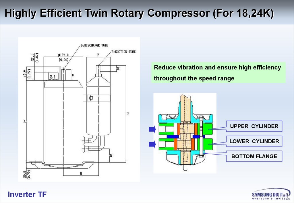
Highly Efficient Twin Rotary Compressor (For 18,24K)Reduce vibration and ensure high efficiency
throughout the speed range
UPPER CYLINDER
LOWER CYLINDER
BOTTOM FLANGE
Inverter TF
15.
Highly Efficient Wide Fin40% of heat transfer area is increased
Preventing clogging, the Initial high efficiency is maintained
throughout the unit’s long lifespan
Conventional Fin
Inverter TF
Wide Fin
16.
Accessory (HB1)Inverter TF
17.
Accessory (WW1)Inverter TF
18.
Accessory (HB2)Inverter TF
19.
Accessory (G3P)Inverter TF
20.
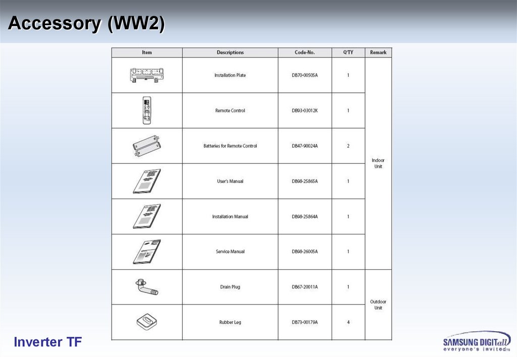
Accessory (WW2)Inverter TF
21.
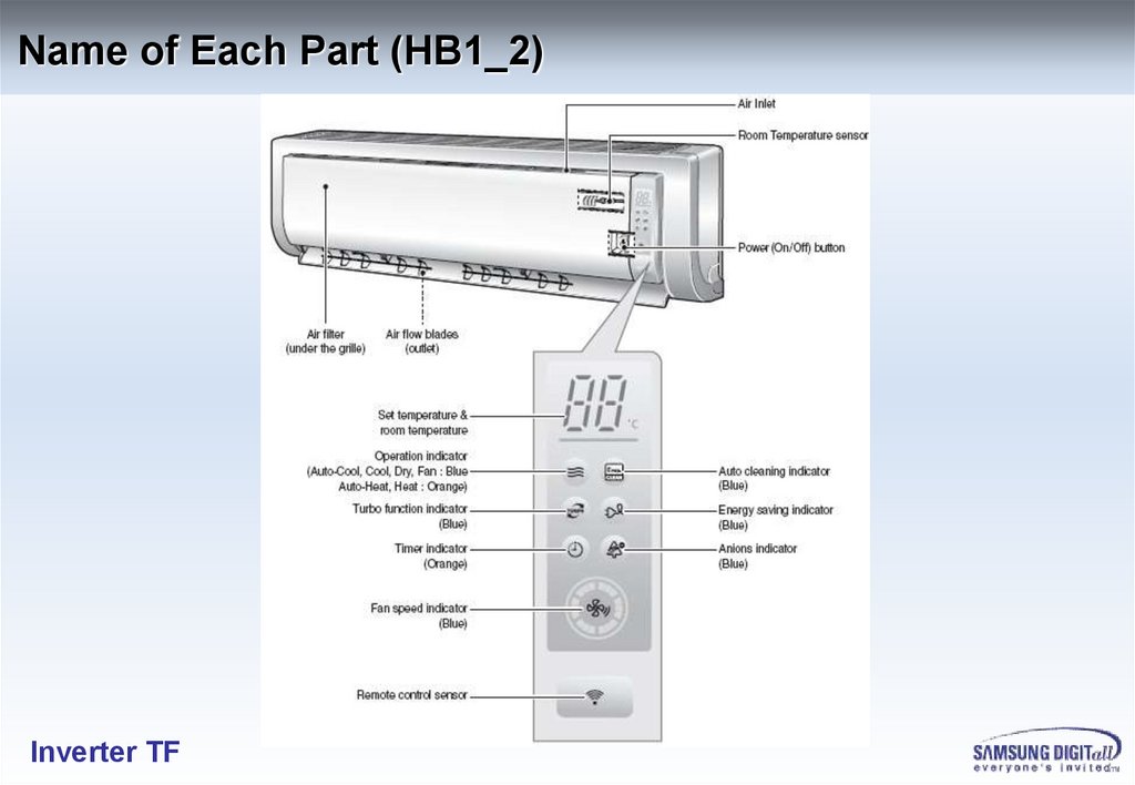
Name of Each Part (HB1_2)Inverter TF
22.
Name of Each Part (WW1_2)Inverter TF
23.
Name of Each Part (G3P)Inverter TF
24.
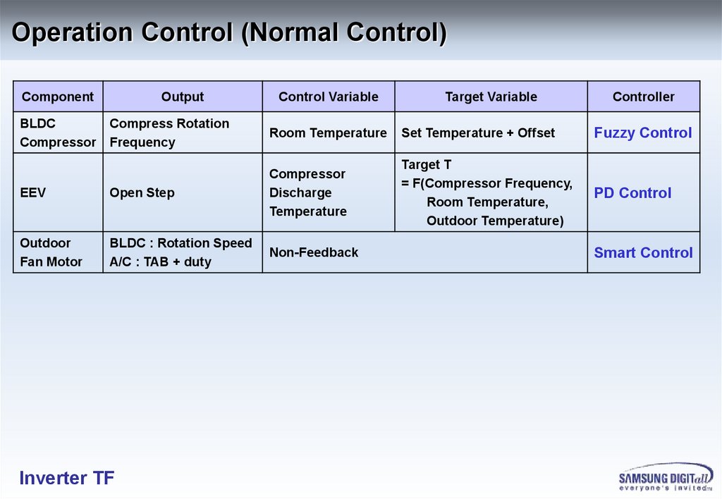
Operation Control (Normal Control)Component
BLDC
Compressor
Output
Control Variable
Target Variable
Controller
Compress Rotation
Frequency
Room Temperature
Set Temperature + Offset
Fuzzy Control
EEV
Open Step
Compressor
Discharge
Temperature
Target T
= F(Compressor Frequency,
Room Temperature,
Outdoor Temperature)
PD Control
Outdoor
Fan Motor
BLDC : Rotation Speed
A/C : TAB + duty
Non-Feedback
Inverter TF
Smart Control
25.
Start ControlCompressor Rotation Frequency
Frequency
Start Frequency
Case 3
Fuzzy Control
2nd Holding Time
= 1minute
2nd Hold
Frequency
Fuzzy Control
1st Hold
Frequency
Start Frequency
Case 2
Fuzzy Control Interval
= 1 minute
Fuzzy Control
Start Frequency
Case 1
1st Holding Time = 1minute
Electric Expansion Valve Open Step (4 minutes)
EEV Open Step = A * Compressor Frequency + B
Inverter TF
Time
26.
Disassembly & Reassembly (HB1 & HB2_INDOOR)Inverter TF
27.
Inverter TF28.
Disassembly & Reassembly (WW1 & WW2_INDOOR)Inverter TF
29.
Disassembly & Reassembly (WW1 & WW2_INDOOR)Inverter TF
30.
Disassembly & Reassembly (G3P_INDOOR)Inverter TF
31.
Disassembly & Reassembly (G3P_INDOOR)Inverter TF
32.
Disassembly & Reassembly (9&12K_OUTDOOR)Inverter TF
33.
Disassembly & Reassembly (9&12K_OUTDOOR)Inverter TF
34.
Disassembly & Reassembly (18K_OUTDOOR)Inverter TF
35.
Disassembly & Reassembly (18K_OUTDOOR)Inverter TF
36.
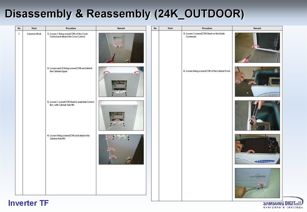
Disassembly & Reassembly (24K_OUTDOOR)Inverter TF
37.
Disassembly & Reassembly (24K_OUTDOOR)Inverter TF
38.
Disassembly & Reassembly (24K_OUTDOOR)Inverter TF
39.
Exploded Views & Part List (HB1_INDOOR)Inverter TF
40.
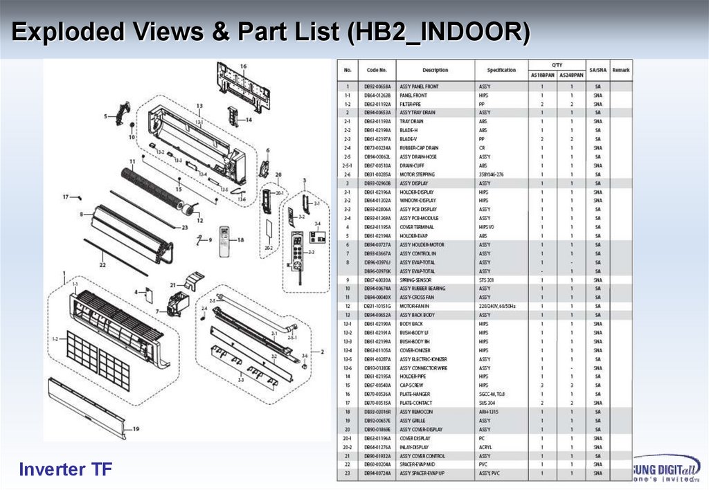
Exploded Views & Part List (HB2_INDOOR)Inverter TF
41.
Exploded Views & Part List (G3P_INDOOR)Inverter TF
42.
Exploded Views & Part List (WW1_INDOOR)Inverter TF
43.
Exploded Views & Part List (WW2_INDOOR)Inverter TF
44.
Exploded Views & Part List (9&12K_OUTDOOR)Inverter TF
45.
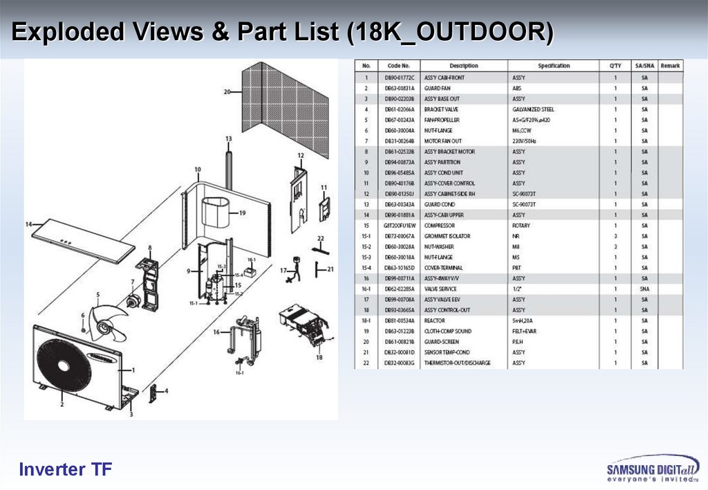
Exploded Views & Part List (18K_OUTDOOR)Inverter TF
46.
Exploded Views & Part List (24K_OUTDOOR)Inverter TF
47.
Exploded Views & Part List (9&12K_Control Out_AC)Inverter TF
48.
Exploded Views & Part List (9&12K_Control Out_485)Inverter TF
49.
Exploded Views & Part List (18&24K_Control Out_485)Inverter TF
50.
Wiring DiagramAC Serial
Inverter TF
485 Serial
- 50 -
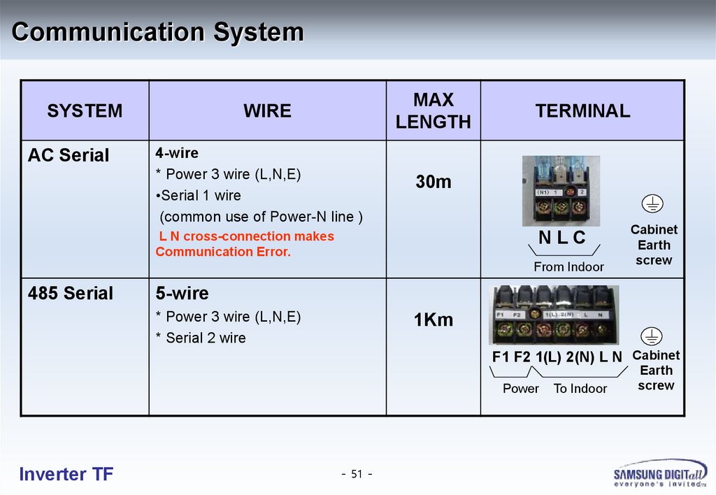
51.
Communication SystemSYSTEM
AC Serial
MAX
LENGTH
WIRE
4-wire
* Power 3 wire (L,N,E)
•Serial 1 wire
(common use of Power-N line )
TERMINAL
30m
NLC
L N cross-connection makes
Communication Error.
From Indoor
485 Serial
Cabinet
Earth
screw
5-wire
* Power 3 wire (L,N,E)
* Serial 2 wire
1Km
F1 F2 1(L) 2(N) L N Cabinet
Power
Inverter TF
- 51 -
To Indoor
Earth
screw
52.
Inverter Controller9/12K BTU (AC)
9/12K BTU (485)
18/24K BTU
2 PCBs
3 PCBs
2 PCBs
Figure
Terminal
Error
Display
Inverter TF
MAIN
Board
Display PCB
- 52 -
53.
Inverter Controller PCB (9/12K OUT_AC)Inverter TF
- 53 -
54.
Inverter Controller PCB (9/12K OUT_485)Inverter TF
- 54 -
55.
Inverter Controller PCB (18/24K OUT)Inverter TF
- 55 -
56.
Inverter Controller (Block Diagram_9/12K AC)Outdoor
Discharge
Defrost
090
COMP
Reactor
BLDC
FAN
IPM
pos.ZC
PFC
IGBT / ZC
FAN
DRIVE
EEPROM
INVERTER
MICOM
R G
LED
AC
COMM.
COM
L
N
Y
AC
RELAY
4way
Inverter TF
POWER
RELAY
INDOOR
- 56 -
Driver
MAIN PCB
EMI FILTER PCB
EEV
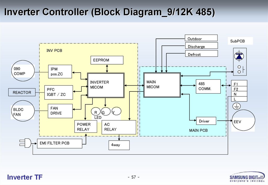
57.
Inverter Controller (Block Diagram_9/12K 485)Outdoor
SubPCB
Discharge
INV PCB
Defrost
EEPROM
090
COMP
IPM
pos.ZC
PFC
IGBT / ZC
REACTOR
FAN
DRIVE
BLDC
FAN
R G
LED
POWER
RELAY
EMI FILTER PCB
Inverter TF
MAIN
MICOM
INVERTER
MICOM
485
COMM.
F1
F2
N
L
Driver
EEV
Y
AC
RELAY
MAIN PCB
4way
- 57 -
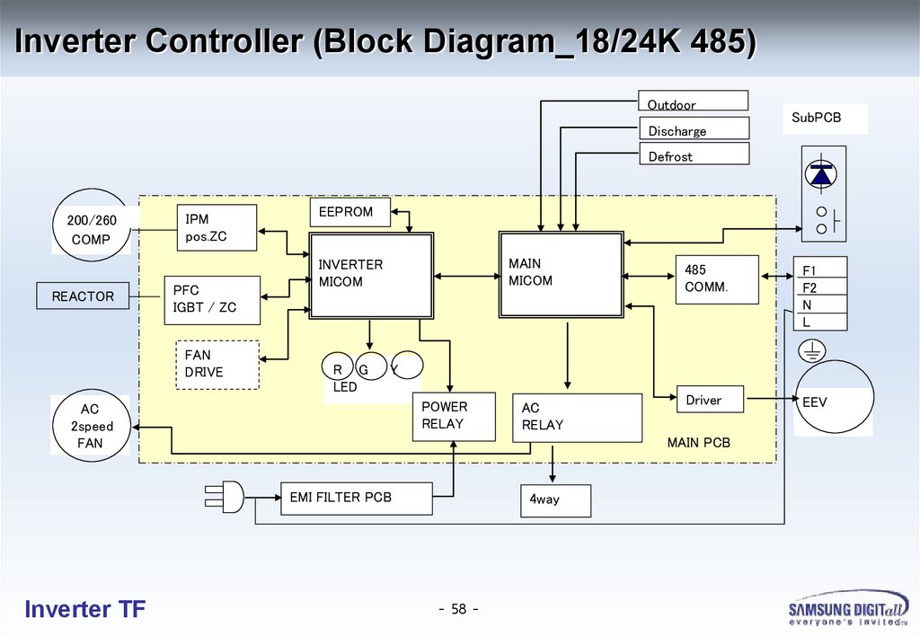
58.
Inverter Controller (Block Diagram_18/24K 485)Outdoor
Discharge
SubPCB
Defrost
200/260
220/260
COMP
REACTOR
IPM
pos.ZC
PFC
IGBT / ZC
FAN
DRIVE
EEPROM
MAIN
MICOM
INVERTER
MICOM
R G
LED
F1
F2
N
L
Driver
EEV
Y
POWER
RELAY
AC
2speed
FAN
AC
RELAY
MAIN PCB
EMI FILTER PCB
Inverter TF
485
COMM.
4way
- 58 -
59.
Inverter Electronics230Vac
50Hz
Power
Pulg
CONVERTER part
310Vdc
RECTIFIERS
Filter
RFI FILTER &
SURGE
SUPPLESSION
Reactor & PFC
INVERTER part
IPM
CAPACI
TOR
0-310V
6600rpm max
Compressor
BLDC
Motor
INDOOR
Unit
Communication
INVERTER & PFC
CONTROLLER
Cycle Controller
Driver
SMPS
EEV
Fan
Motor
Temperature
Sensor
Block Diagram of Outdoor Unit Inverter Controller
Inverter TF
- 59 -
Sensorless
Rotor
Position
Detector
60.
Intelligent Temperature ControlRobust Fuzzy Control
Rapid Temperature Response
High Stability
High Reliability
Inverter TF
61.
A S 12B P A N R e s id e n tia l T e s t F o r C o o lin g40
5000
Inverter
AS12BPAN
35
4500
4000
27℃ S e ttin g
30
25℃ S e ttin g
23℃ S e ttin g
25
3000
20
2500
Non Inverter
AS12HPA
15
2000
1500
10
1000
5
500
0
0
0
60
120
180
240
300
T im e(M in)
R o o m T e m p _A S 12B P A N
P o w e r In p u t_A S 12B P A N
P o w e r In p u t_A S 12H P A
Inverter TF
R o o m T e m p _A S 12H P A
In te g P o w e r In p u t_A S 12B P A N
In te g P o w e r In p u t_A S 12H P A
360
P ow er Input(W )
R oom Tem p.(℃)
3500
62.
A S 12B P A N R e s id e n tia l T e s t fo r H e a tin g5000
30
Inverter
AS12BPAN
4500
4000
3500
20
3000
Non Inverter
AS12HPA
15
2500
2000
10
1500
1000
5
500
0
0
60
180
120
240
300
T im e (M in )
R o o m T e m p _A S 12B P A N
P o w e r In p u t_A S 12B P A N
P o w e r In p u t_A S 12H P A
Inverter TF
R o o m T e m p _A S 12H P A
In te g P o w e r In p u t_A S 12B P A N
In te g P o w e r In p u t_A S 12H P A
0
360
P o w er In p ut(W )
R o o m T em p .(℃)
25
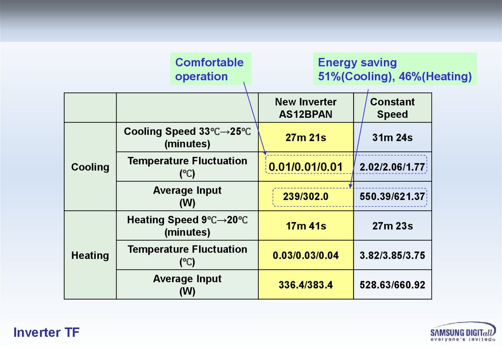
63.
Comfortableoperation
Cooling
Heating
Inverter TF
Energy saving
51%(Cooling), 46%(Heating)
New Inverter
AS12BPAN
Constant
Speed
Cooling Speed 33℃→25℃
(minutes)
27m 21s
31m 24s
Temperature Fluctuation
(℃)
0.01/0.01/0.01
2.02/2.06/1.77
Average Input
(W)
239/302.0
550.39/621.37
Heating Speed 9℃→20℃
(minutes)
17m 41s
27m 23s
Temperature Fluctuation
(℃)
0.03/0.03/0.04
3.82/3.85/3.75
Average Input
(W)
336.4/383.4
528.63/660.92
64.
ROTARY COMPRESSOR APPLICATION SHEETNo
1
Items
Operational standards and limits
Operating frequency range
15 ~ 110 rps (15 ~ 85Hz)
Quantity of refrigerant charge
2000 g (Need to the special discussion when refrigerant
quantity is over than 2000 g.)
Usage range in ordinary load
Discharge pressure : Less than 3.29MPa (33.5 ㎏/㎠)
Discharge temperature : Less than 100℃
Motor coil temperature : Less than 100℃
4
Usage range of pressure
Refer to pressure guarantee range (Page 6~7 )
5
Discharge gas temp.
Max. 115℃
6
Motor winding temp.
Max. 130℃
Bottom shell temperature
Min. 5 ℃ higher than condensing temp.
(Except transient condition)
8
On-Off cycle
Less than 6 cycle/hour => total 200,000 cycles
9
Liquid back operation
No liquid back with current variation and strange noise.
Vibration of tubing
Tubing vibration displacement : Max 0.8mm (±10% of rated voltage)
If the resonance of the pipe can be checked, above condition is not
necessary
Pipe Stress (Operation)
At continuous operation, stress of bottom of discharge part in accumulator
must be below 15MPa (1.5㎏/㎟)
12
Pipe Stress
(Stop starting)
On starting ,stopping and operation, the stress of bottom of discharge part in
accumulator must be below 29.5MPa (3㎏/㎟)
13
Allowable gradient at the time of the
installation
5 degree and below
2
3
7
10
11
Inverter TF
65.
PRESSURE GUARANTEE RANGEACCORDING TO LOW AND HIGH PRESSURE
4.5
4.12
45 90Hz
Pd (MPaG)
4.0
3.43
3.5
3.23
30Hz
110Hz
3.0
2.74
15Hz
2.5
2.0
1.5
A
1.0
0.79
1.03 1.18 1.30 1.42
0.5
0.59
0.0
0
0.2
0.4
0.6
0.8
1
1.2
1.4
Ps (MPaG)
Inverter TF
G8T260 Operating Envelope
1.6
66.
Protection Control – Overload ProtectionIndoor unit
Heat Exchanger
Temperature
T_Trip
T_Down
T_Hold
T_UpRelease
Prevent to Raise
Compressor Frequency
Inverter TF
Compressor Frequency
Down Region
67.
Protection Control – Discharge Temperature Over Heat ProtectionD ischarg e
Tem p erature
T[℃]
C om p
T rip
T_trip
H z D ow n
H z D ow n
T_d o w n
P revent to
raise H z
T_ho ld
10m in
T_U p R elease
stay
시간[s]
Inverter TF
68.
Protection Control – Over Current ProtectionCurrent [A]
Current [
I_ trip
I_ trip
I_D
I_down
own_Heat_10
0.4
2.0A
Id′
Hz Down 1 Hz 2s ec
I_down_cool_30
I_D
Hz Down 1 Hz 2s ec
own_Heat_50
Hz Hold
I_down_cool_50
Hz Hold
Cooling Mode
Inverter TF
Outdoor
Temperature
[℃]
Heating Mode
Outdoor
Temperature
[℃]
69.
Protection Control – Freezing Evaporator Protection1st P ro tectio n S tart
Indo o r
H eat E xchang er
Tem p erature
T_R elease
2 nd P ro tectio n S tart
R elease
T_D o w n
T_C o m p O FF
C om p
9 m in
M inim um
2m in 50sec
S tart F req uency
P ro tectio n
F req uency
O utdo o r Fan
O ff
On
On
O ff
Indo o r Fan
U ser S et A irflo w
U ser S et A irflo w
LL
Inverter TF
70.
Indoor Unit Display For Error Detecting (HB1/2,G3P)Inverter TF
71.
Indoor Unit Display For Error Detecting (WW1/2)Inverter TF
72.
Outdoor LED Error DisplayInverter TF
73.
Error OperationIndoor unit
Error Code
Outdoor unit
Error Cause
Display
Operation OFF
Display
Operation OFF
E102
Indoor/Outdoor Communication Time Out (1 minute)
immediately
immediately
immediately
immediately
E202
60 Packet Over data
immediately
immediately
immediately
immediately
E203
Communication Error between Outdoor Main and Inverter
Micom (Occurred after I minute detection in Main and Inverter)
immediately
immediately
immediately
immediately
E221
Outdoor Temp. Sensor Error (OPEN/SHORT ERROR)
immediately
immediately
immediately
immediately
E237
COND Temp. Sensor Error (OPEN/SHORT ERROR)
immediately
immediately
immediately
immediately
E260
Inverter Compressor Discharge Temp. sensor Error
(OPEN/SHORT ERROR)
immediately
immediately
immediately
immediately
E416
Discharge over temperature (Dual/Single)
3rd detection
3rd detection
immediately
3min restart
3rd detection
E462
I_Trip error / PFC Over current
3rd detection
3rd detection
immediately
3min restart 3rd
detection
E440/441
Operation condition secession
immediately
immediately
immediately
immediately
E460
Outdoor unit-Indoor unit Communication wire Voltage Detection
immediately
immediately
immediately
immediately
E554
Outdoor unit Refrigerant Full Leakage (Gas Leak)
3rd detection
3rd detection
immediately
3min restart
3rd detection
E458
Outdoor door Fan Error
immediately
immediately
immediately
10 min restart
E556
capacity miss match
immediately
immediately
immediately
immediately
Inverter TF
74.
Indoor unitError Code
Outdoor unit
Error Cause
Display
Operation OFF
Display
Operation OFF
E464
IPM Over Current (O.C)
9th detection
9th detection
immediately
3min restart 9th
detection
E461
Comp Starting error
5th detection
5th detection
immediately
3min restart 5th
detection
E473
Comp Lock error
3rd detection
3rd detection
immediately
3min restart 3rd
detection
E466
DC-Link voltage under/over error
immediately
immediately
immediately
immediately
E468
current sensor error
immediately
immediately
immediately
immediately
E465
Comp Vlimit error
9th detection
9th detection
immediately
3min restart 9th
detection
E471
OTP error
immediately
immediately
immediately
immediately
E467
Comp rotation error
3rd detection
3rd detection
immediately
3min restart 3rd
detection
E469
DC-Link valtage sensor error
immediately
immediately
immediately
immediately
E472
AC Line Zero Cross Signal out
immediately
immediately
immediately
immediately
Inverter TF
75.
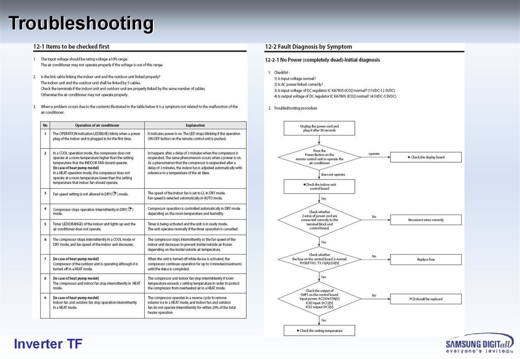
TroubleshootingInverter TF
76.
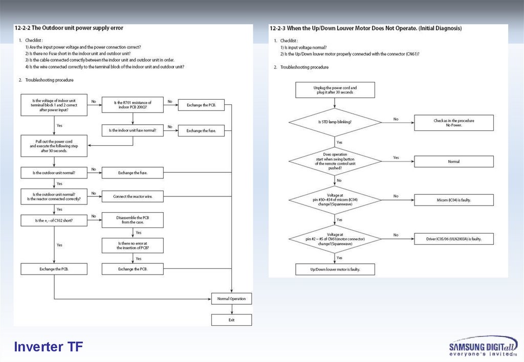
Inverter TF77.
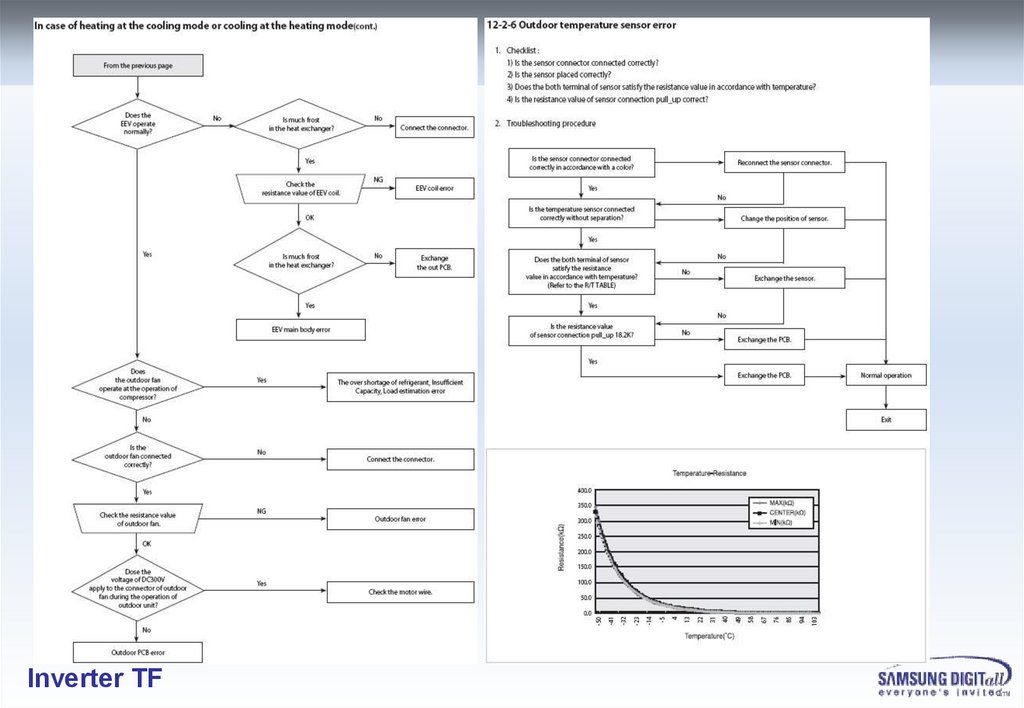
Inverter TF78.
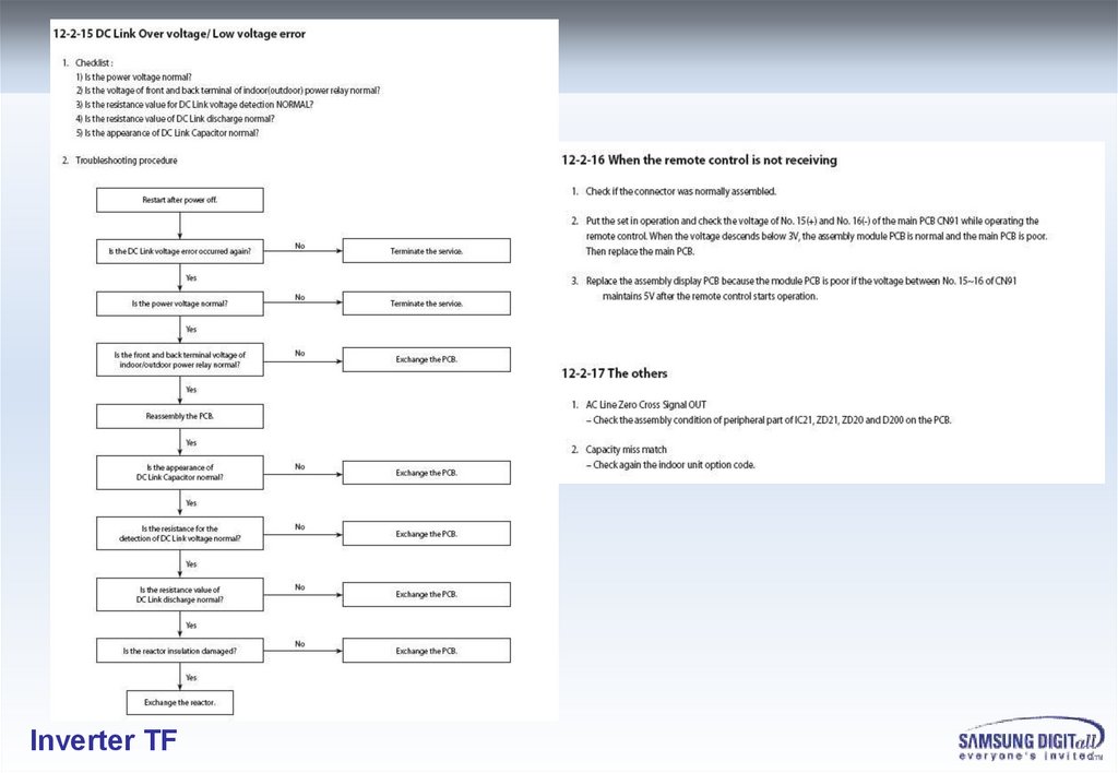
Inverter TF79.
Inverter TF80.
Inverter TF81.
Inverter TF82.
Inverter TF83.
Inverter TF84.
Wiring Diagram (HB1_INDOOR)Inverter TF
85.
Wiring Diagram (HB2_INDOOR)Inverter TF
86.
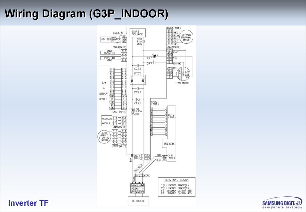
Wiring Diagram (G3P_INDOOR)Inverter TF
87.
Wiring Diagram (WW1/2_INDOOR)Inverter TF
88.
Wiring Diagram (HB1_OUTDOOR)Inverter TF
89.
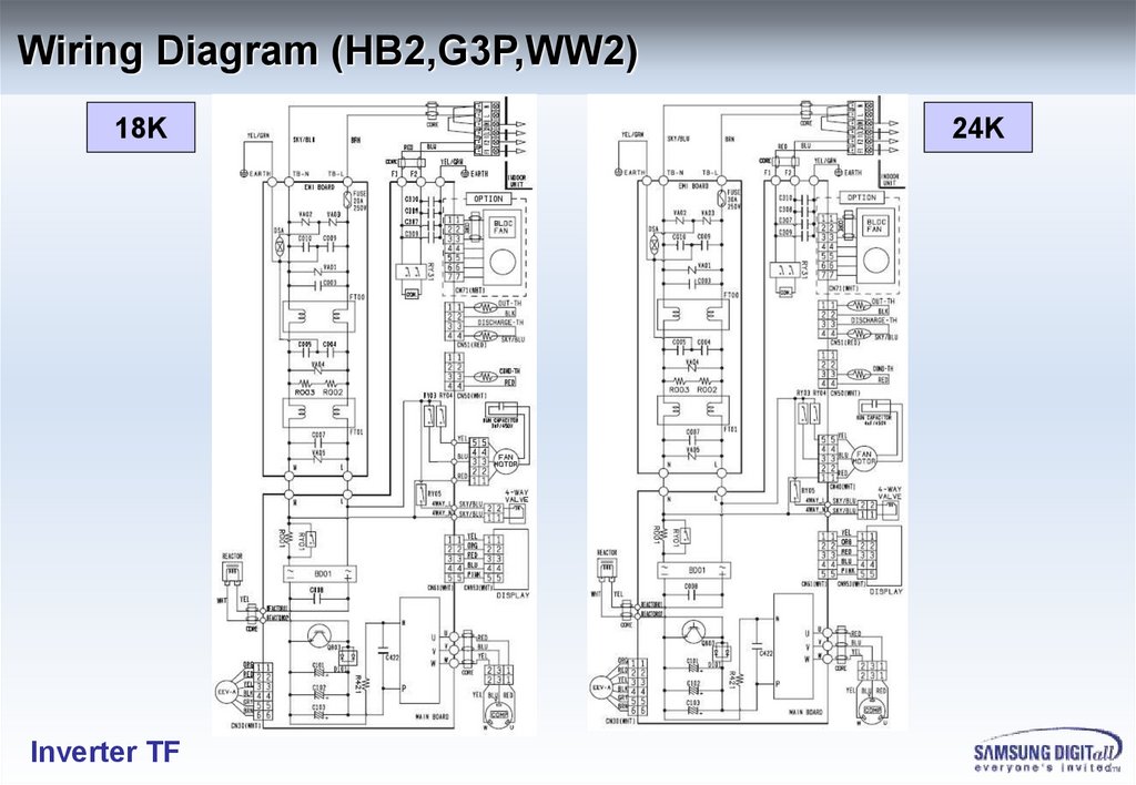
Wiring Diagram (HB2,G3P,WW2)18K
Inverter TF
24K
90.
Check Point In Service1. Temperature sensor off from the holder
Correct temperature detection can control the air conditioner
2. To loosen screws makes controller trouble
,especially Heat-Sink part
Inverter TF
- 90 -
91.
3. Always putting silicon greaseon the surface between Power semicondoctor and heatsink
Also putting insulation mica on non insulated power semiconductor.
4. Confirm POWER OFF and LED OFF
before Connecting / Dis-Connecting BLDC FAN socket.
Connecting / Dis-connecting of BLDC FAN SOCKET can make
Damage to both PCB assy and BLDC FAN MOTOR (9K/12K model).
5. Make sure the tight power wire connection
to the terminal block screw and OUTLET (power plug).
This cause troubles like fire, reset trouble, etc.
Inverter TF
- 91 -
92.
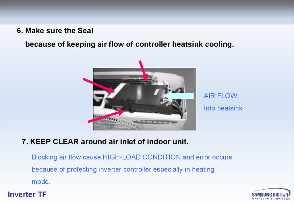
6. Make sure the Sealbecause of keeping air flow of controller heatsink cooling.
AIR FLOW
Into heatsink
7. KEEP CLEAR around air inlet of indoor unit.
Blocking air flow cause HIGH-LOAD CONDITION and error occurs
because of protecting inverter controller especially in heating
mode.
Inverter TF
93.
Thank you.Inverter TF