


 Электроника
Похожие презентации:


"Typhoon" Project Training Manual (Easytronics)
1.
ConfidentialTyphoon Project Training Manual
(Easytronics )
Jan.2008
Oven R&D Group
2.
1. Precaution1-1. Safety Precaution
Follow these special safety precautions during repair or inspection.
1. All repairs should be done in accordance with the procedures described in this manual.
This product complies with Federal Performance Standard 21 CFR Subchapter J(DHHS).
2. Check all grounds.
3. Do not power the OVEN from a “2 - prong” AC cord. Be sure that all of the built – in
protective devices are replaced. Restore any missing protective shields.
4. When reinstalling the chassis and its assemblies, be sure to restore all protective
devices including nonmetallic control knobs and compartment covers.
5. Make sure that there are no cabinet openings through which people --particularly
children --might insert objects and contact dangerous voltages.
6. Service technicians should remove their watches while repairing an OVEN.
7. Design Alteration Warning:
Use exact replacement parts only, i.e., only those that are specified in the drawings and
parts lists of this manual. Never alter or add to the mechanical or electrical design of the
OVEN. Any design changes or additions will void the manufacturer’s warranty.
Always unplug the unit’s AC power cord from the AC power source before attempting to
remove or reinstall any component or assembly.
3.
1. Precaution1-1. Safety Precaution
8. Never defeat any of the B+ voltage interlocks. Do not apply AC power to the unit (or any
of its assemblies) unless all solid-state heat sinks are correctly installed.
9. Some semiconductor (“solid state”) devices are easily damaged by static electricity.
Such components are called Electro statically Sensitive Devices (ESDs). Examples
include integrated circuits and field effect transistors. Immediately before handling any
semiconductor components or assemblies, drain the electrostatic charge from your body
by touching a known earth ground.
10. Always connect a test instrument’s ground lead to the instrument chassis ground
before connecting the positive lead; always remove the instrument’s ground lead last.
11. Use replacement components that have the same ratings, especially for flame
resistance and dielectric strength specifications. A replacement part that does not have
the same safety characteristics as the original might create shock, re or other hazards.
NOTE: Connect the oven to a 20 A. When connecting the oven to a 15 A, make sure that circuit
breaker can operate.
12. Never touch any circuit wiring with your hand nor with uninsulated tool during operation.
4.
revised Page2. Features and Specifications
2-1. Features
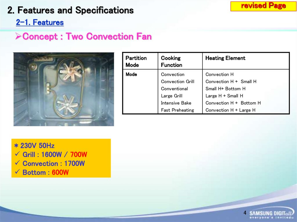
Concept : Two Convection Fan
Partition
Mode
Cooking
Function
Heating Element
Mode
Convection
Convection Grill
Conventional
Large Grill
Intensive Bake
Fast Preheating
Convection H
Convection H + Small H
Small H+ Bottom H
Large H + Small H
Convection H + Bottom H
Convection H + Large H
* 230V 50Hz
Grill : 1600W / 700W
Convection : 1700W
Bottom : 600W
4
5.
2. Features and Specificationsrevised Page
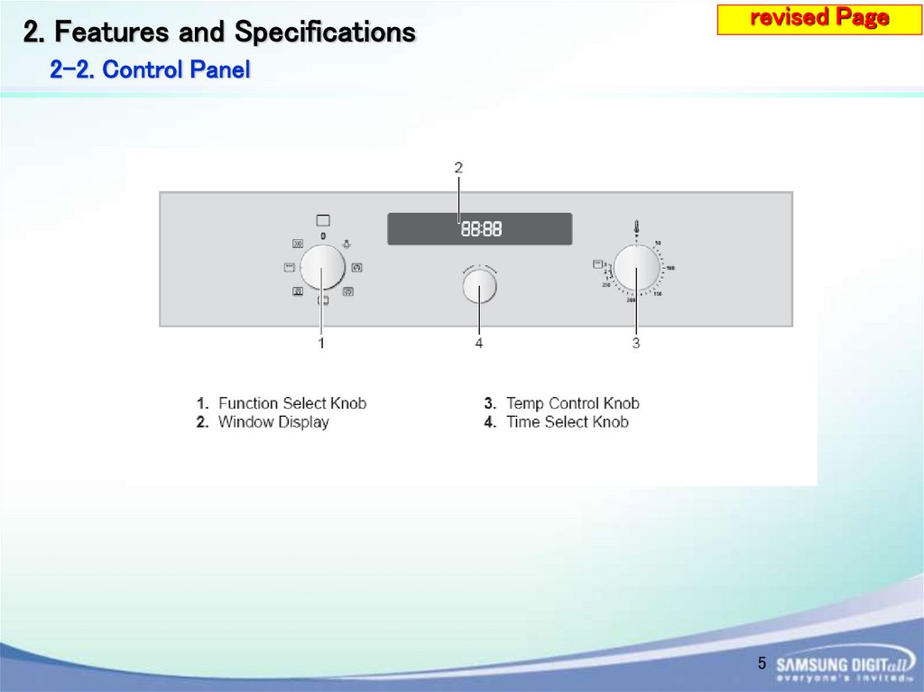
2-2. Control Panel
5
6.
2. Features and Specificationsrevised Page
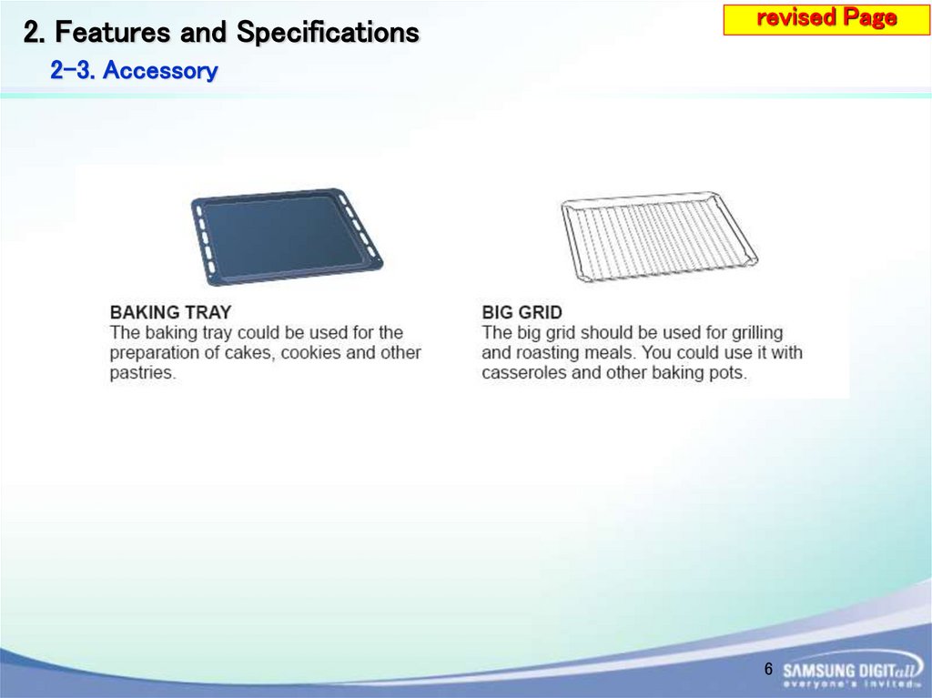
2-3. Accessory
6
7.
revised Page2. Features and Specifications
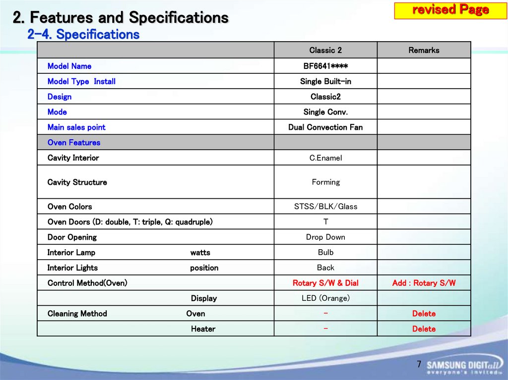
2-4. Specifications
Classic 2
Model Name
BF6641****
Model Type Install
Single Built-in
Design
Classic2
Mode
Single Conv.
Main sales point
Remarks
Dual Convection Fan
Oven Features
Cavity Interior
C.Enamel
Cavity Structure
Forming
Oven Colors
STSS/BLK/Glass
Oven Doors (D: double, T: triple, Q: quadruple)
Door Opening
T
Drop Down
Interior Lamp
watts
Bulb
Interior Lights
position
Back
Control Method(Oven)
Rotary S/W & Dial
Display
Cleaning Method
Add : Rotary S/W
LED (Orange)
Oven
-
Delete
Heater
-
Delete
7
8.
revised Page2. Features and Specifications
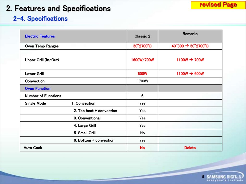
2-4. Specifications
Remarks
Electric Features
Classic 2
Oven Temp Ranges
50~2700℃
40~300 50~2700℃
Upper Grill (In/Out)
1600W/700W
1100W 700W
Lower Grill
600W
1100W 600W
Convection
1700W
Oven Function
Number of Functions
Single Mode
Auto Cook
6
1. Convection
Yes
2. Top heat + convection
Yes
3. Conventional
Yes
4. Large Grill
Yes
5. Small Grill
No
6. Bottom + convection
Yes
No
Delete
8
9.
revised Page2. Features and Specifications
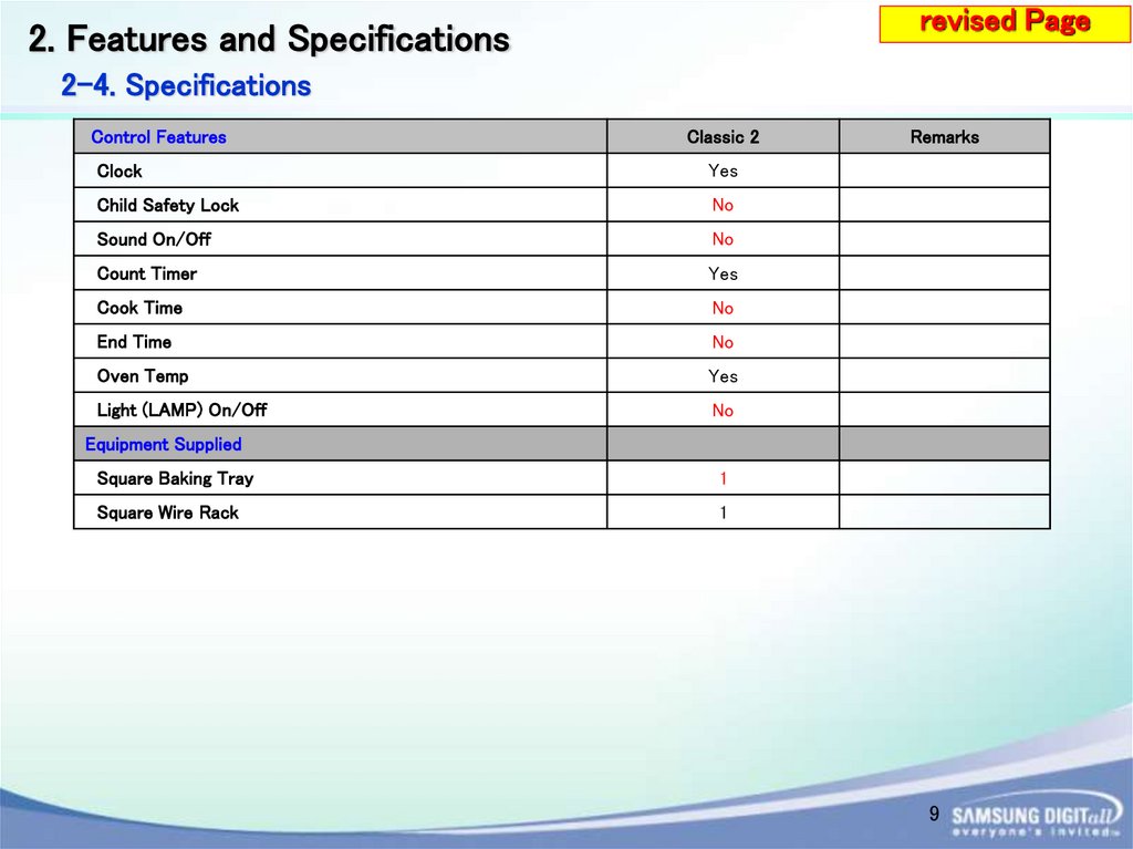
2-4. Specifications
Control Features
Classic 2
Clock
Yes
Child Safety Lock
No
Sound On/Off
No
Count Timer
Yes
Cook Time
No
End Time
No
Oven Temp
Yes
Light (LAMP) On/Off
No
Remarks
Equipment Supplied
Square Baking Tray
1
Square Wire Rack
1
9
10.
3. Installation3-1. How to install the oven
IMPORTANT
Any electrical installation work must be carried out by a qualified electrician / competent person.
The oven must be installed according to the instructions supplied.
Safety Instructions for the Installer
Protection against access to live parts must be guaranteed by the installation.
The unit in which the appliance is fitted must satisfy the requirements of DIN 68930 in respect
of stability. This oven must be installed by qualified personnel to the relevant Standards.
This oven is heavy. Take care when moving it. Remove all packaging, both inside and outside
the oven before using the oven. Do not attempt to modify the oven in any way.
10
11.
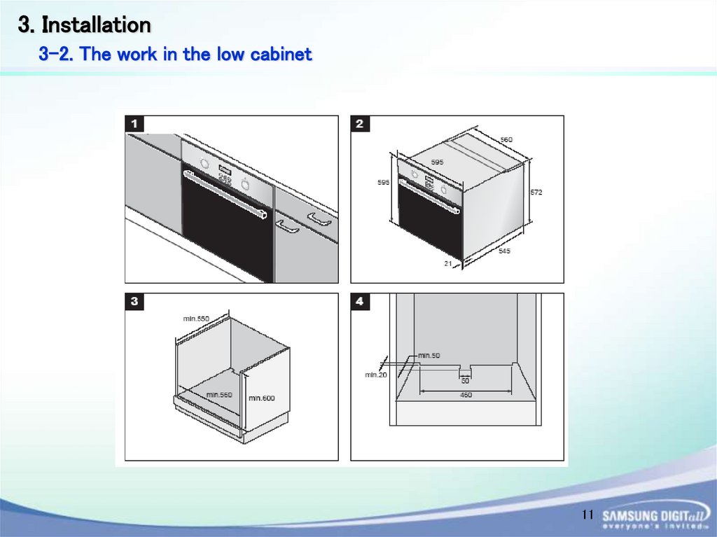
3. Installation3-2. The work in the low cabinet
11
12.
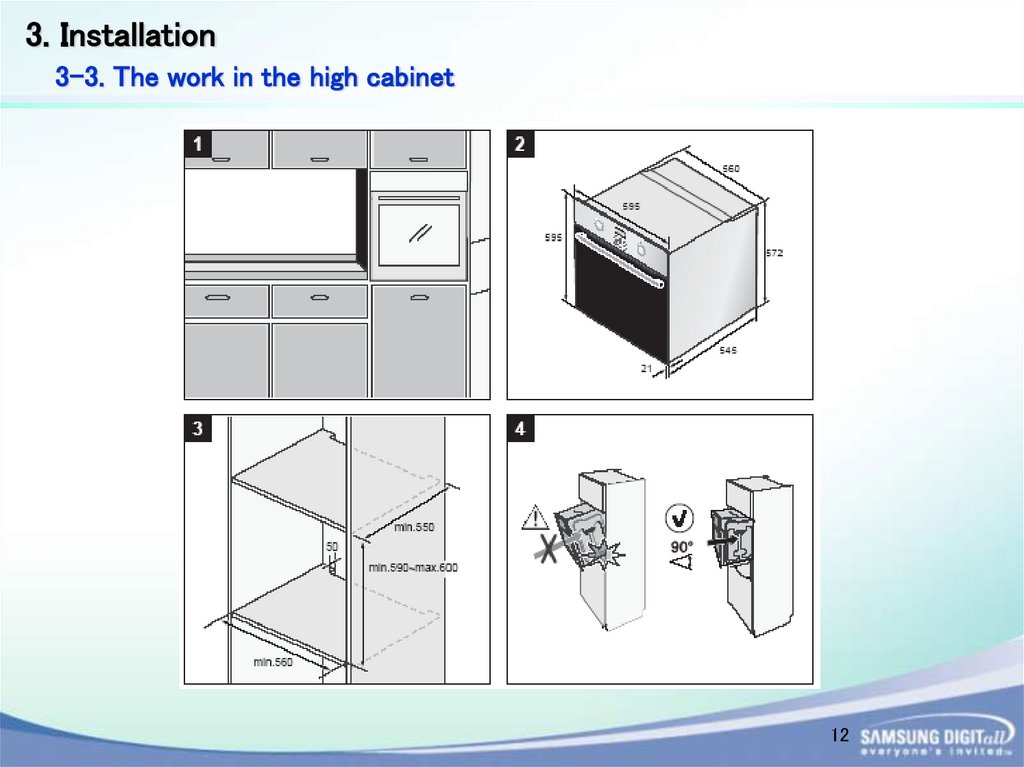
3. Installation3-3. The work in the high cabinet
12
13.
3. Installation3-4. Power connection
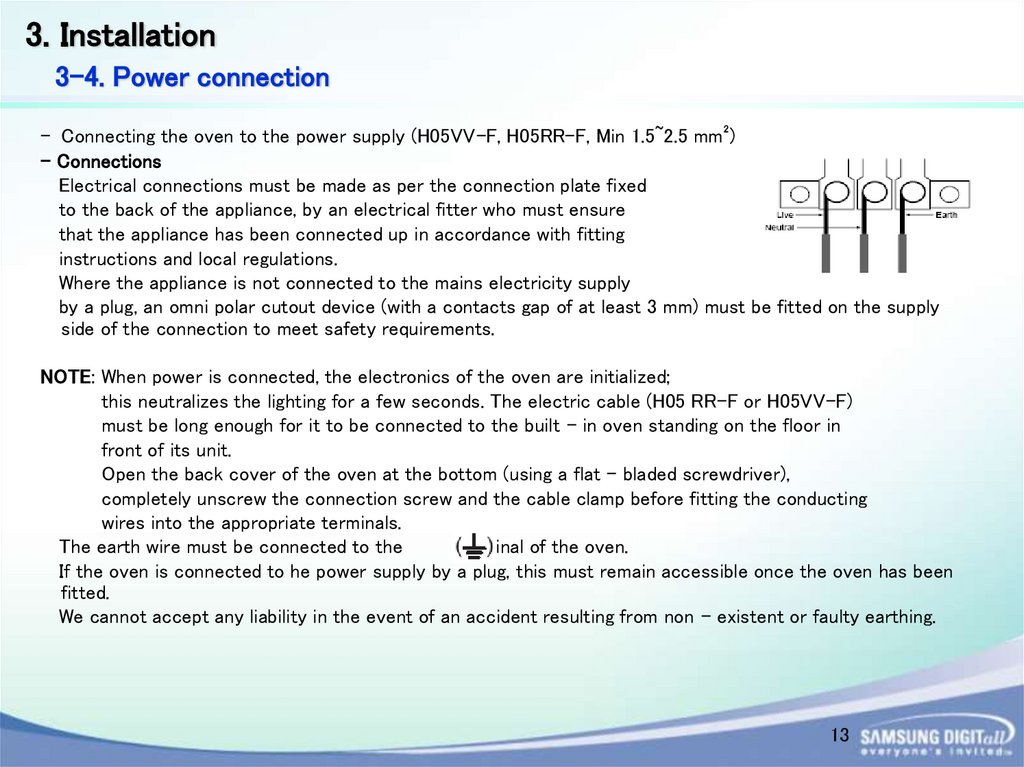
- Connecting the oven to the power supply (H05VV-F, H05RR-F, Min 1.5~2.5 mm²)
- Connections
Electrical connections must be made as per the connection plate fixed
to the back of the appliance, by an electrical fitter who must ensure
that the appliance has been connected up in accordance with fitting
instructions and local regulations.
Where the appliance is not connected to the mains electricity supply
by a plug, an omni polar cutout device (with a contacts gap of at least 3 mm) must be fitted on the supply
side of the connection to meet safety requirements.
NOTE: When power is connected, the electronics of the oven are initialized;
this neutralizes the lighting for a few seconds. The electric cable (H05 RR-F or H05VV-F)
must be long enough for it to be connected to the built - in oven standing on the floor in
front of its unit.
Open the back cover of the oven at the bottom (using a flat - bladed screwdriver),
completely unscrew the connection screw and the cable clamp before fitting the conducting
wires into the appropriate terminals.
The earth wire must be connected to the
terminal of the oven.
If the oven is connected to he power supply by a plug, this must remain accessible once the oven has been
fitted.
We cannot accept any liability in the event of an accident resulting from non - existent or faulty earthing.
13
14.
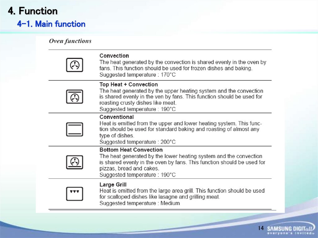
4. Function4-1. Main function
14
15.
4. Functionrevised Page
4-2. Setting the Cooking Function mode
15
16.
4. Functionrevised Page
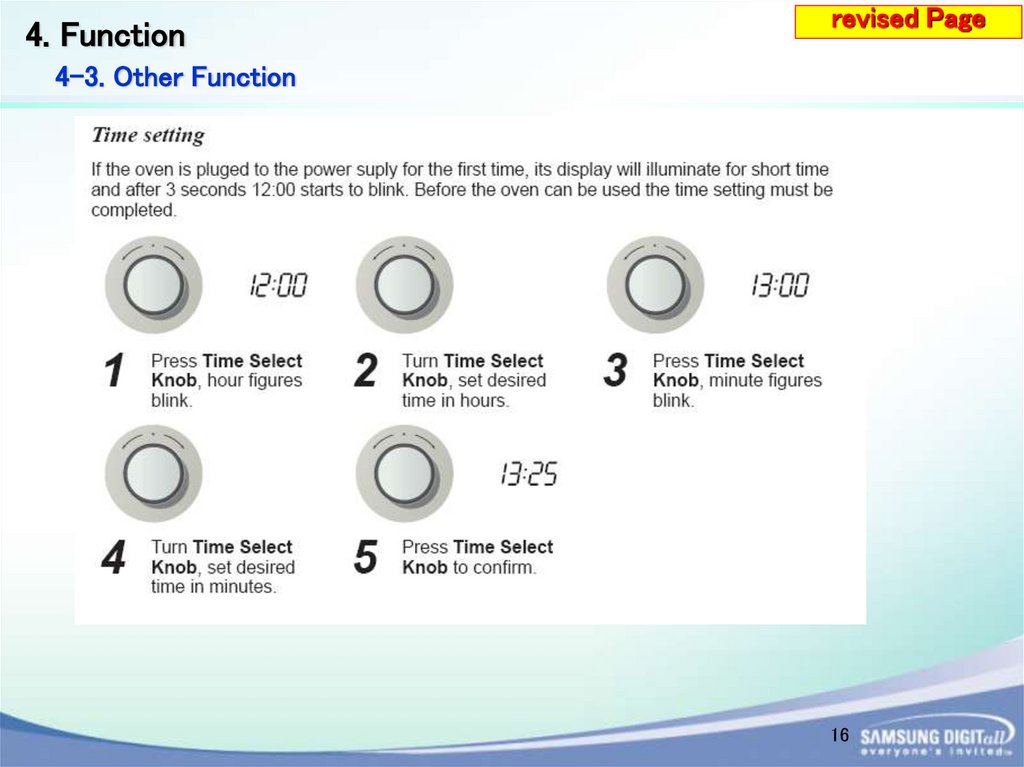
4-3. Other Function
16
17.
4. Functionrevised Page
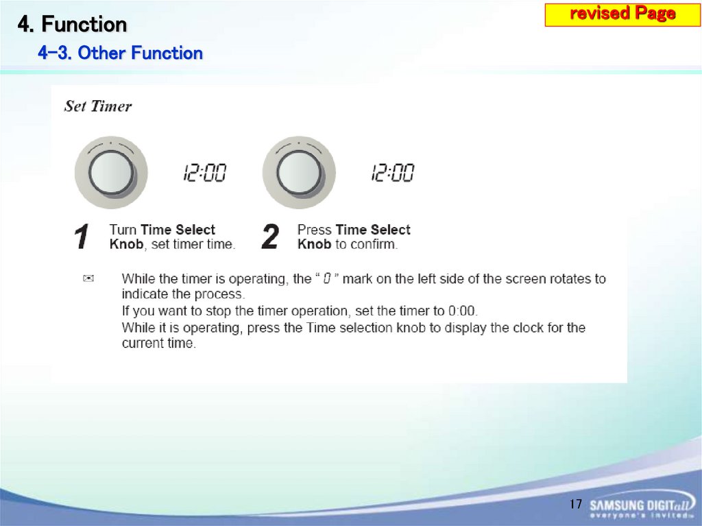
4-3. Other Function
17
18.
5. Service Informationrevised Page
5-1. Thermo cut-out
Two pieces of thermo cut-out are mounted in order to monitor abnormal operation of the oven and
make the oven stop safely.
18
19.
revised Page5. Service Information
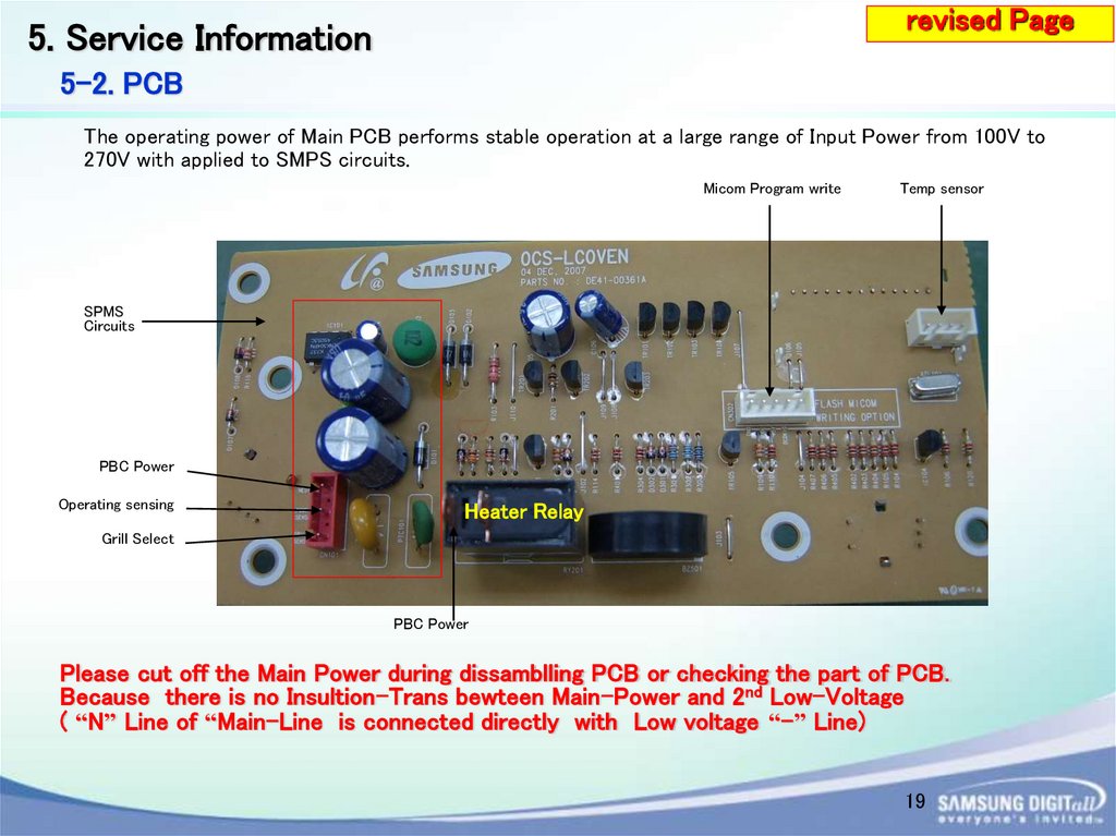
5-2. PCB
The operating power of Main PCB performs stable operation at a large range of Input Power from 100V to
270V with applied to SMPS circuits.
Micom Program write
Temp sensor
SPMS
Circuits
PBC Power
Operating sensing
Heater Relay
Grill Select
PBC Power
Please cut off the Main Power during dissamblling PCB or checking the part of PCB.
Because there is no Insultion-Trans bewteen Main-Power and 2nd Low-Voltage
( “N” Line of “Main-Line is connected directly with Low voltage “-” Line)
19
20.
revised Page5. Service Information
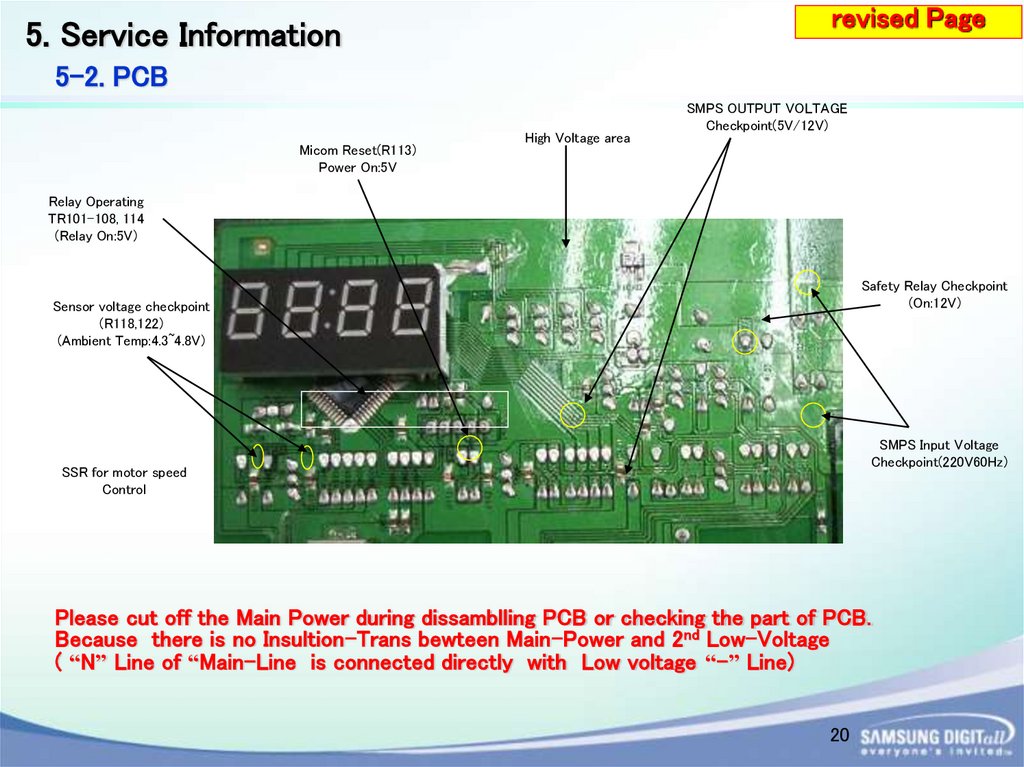
5-2. PCB
Micom Reset(R113)
Power On:5V
High Voltage area
SMPS OUTPUT VOLTAGE
Checkpoint(5V/12V)
Relay Operating
TR101-108, 114
(Relay On:5V)
Safety Relay Checkpoint
(On:12V)
Sensor voltage checkpoint
(R118,122)
(Ambient Temp:4.3~4.8V)
SMPS Input Voltage
Checkpoint(220V60Hz)
SSR for motor speed
Control
Please cut off the Main Power during dissamblling PCB or checking the part of PCB.
Because there is no Insultion-Trans bewteen Main-Power and 2nd Low-Voltage
( “N” Line of “Main-Line is connected directly with Low voltage “-” Line)
20
21.
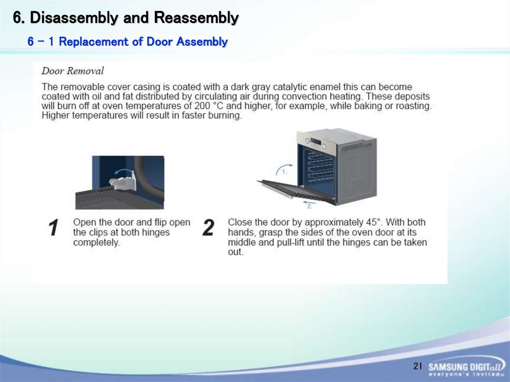
6. Disassembly and Reassembly6 - 1 Replacement of Door Assembly
21
22.
6. Disassembly and Reassemblyrevised Page
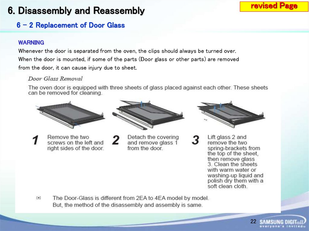
6 - 2 Replacement of Door Glass
WARNING
Whenever the door is separated from the oven, the clips should always be turned over.
When the door is mounted, if some of the parts (Door glass or other parts) are removed
from the door, it can cause injury due to sheet.
22
23.
4. Disassembly and Reassembly6 - 3 Replacement of the rear oven Lamp Bulb
6-3-1 Take off the cap by turning counterclockwise.
6-3-2 Remove the metal ring and the sheet ring and clean the
glass cap.
6-3-3 If necessary, replace the bulb with a 25 watt, 230 V,
300 °C heat - resistant oven light bulb.
6-3-4 Fit the metal and the sheet ring to the glass cap.
6-3-5 Replace the glass cap.
23
24.
6. Disassembly and Reassemblyrevised Page
6 - 4 Replacement of Assy Control Box
6 - 4 - 1 Remove a connector from the main
PCB.
24
25.
6. Disassembly and Reassemblyrevised Page
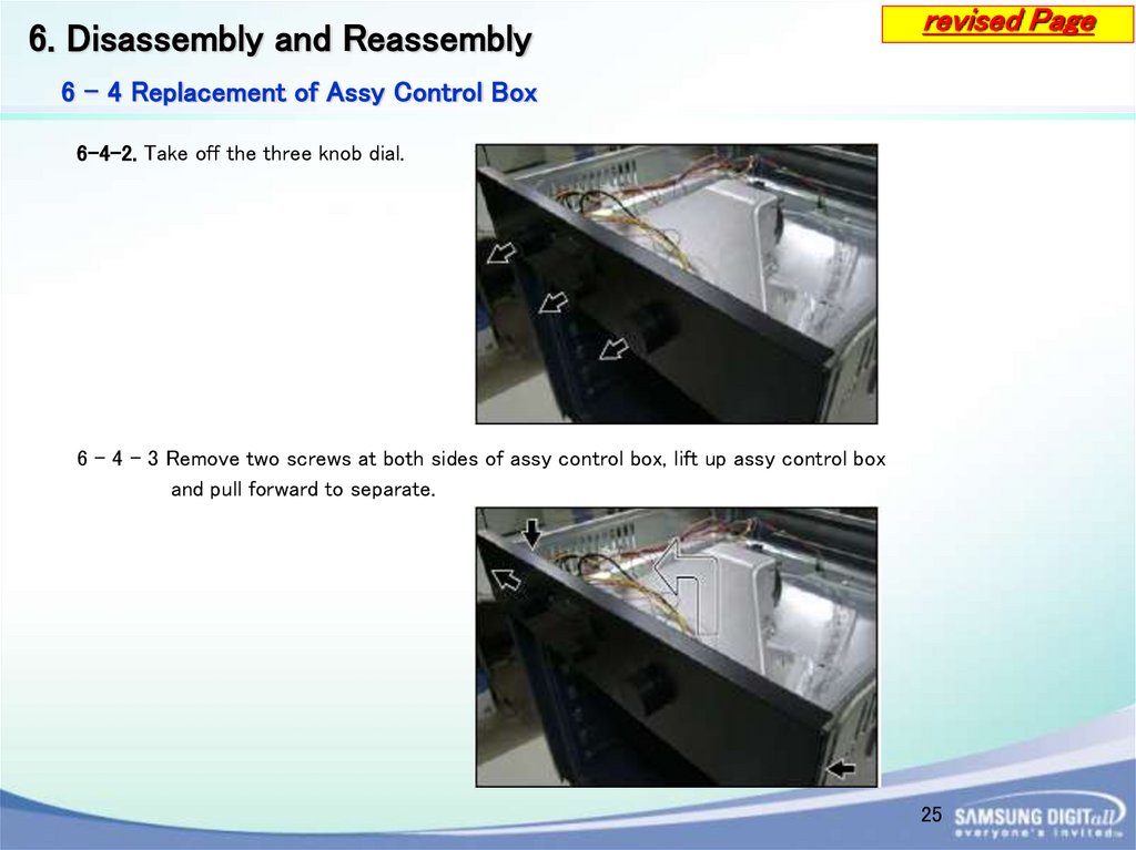
6 - 4 Replacement of Assy Control Box
6-4-2. Take off the three knob dial.
6 - 4 - 3 Remove two screws at both sides of assy control box, lift up assy control box
and pull forward to separate.
25
26.
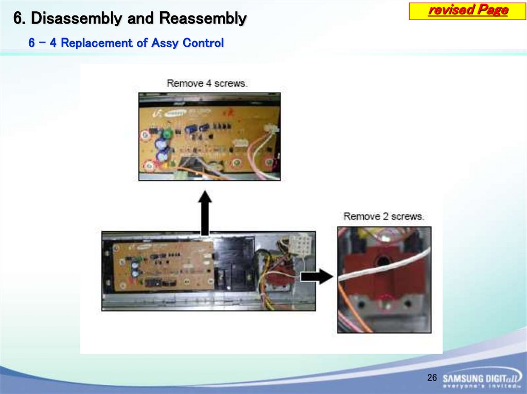
6. Disassembly and Reassemblyrevised Page
6 - 4 Replacement of Assy Control
26
27.
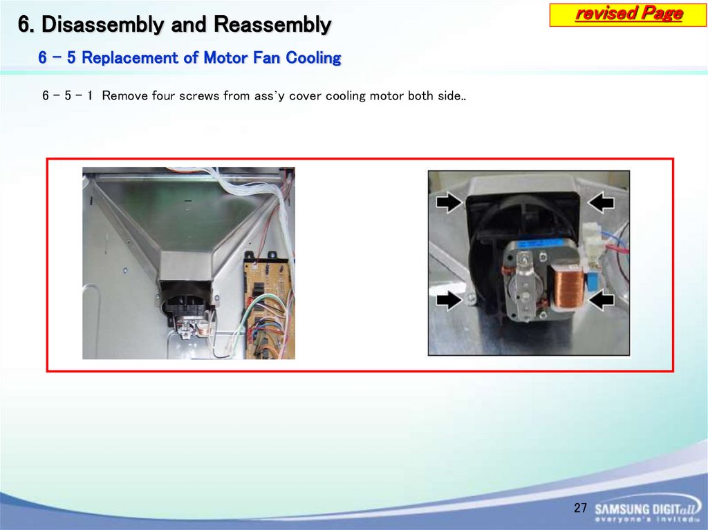
6. Disassembly and Reassemblyrevised Page
6 - 5 Replacement of Motor Fan Cooling
6 - 5 - 1 Remove four screws from ass’y cover cooling motor both side..
27
28.
6. Disassembly and Reassembly6 - 6 Replacement of Motor Convection
6 - 6 - 1 Remove four screws at the back
inside cavity to separate the cover
casing.
6 - 6 - 2 Turn flange nut to the left to release
and separate spacer fan convection
and fan convection.
6 - 6 - 3 Remove three screws securing motor
convection.
28
29.
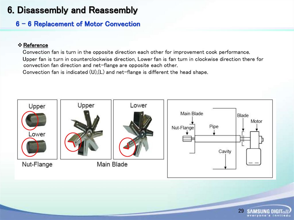
6. Disassembly and Reassembly6 - 6 Replacement of Motor Convection
Reference
Convection fan is turn in the opposite direction each other for improvement cook performance.
Upper fan is turn in counterclockwise direction, Lower fan is fan turn in clockwise direction there for
convection fan direction and net-flange are opposite each other.
Convection fan is indicated (U),(L) and net-flange is different the head shape.
29
30.
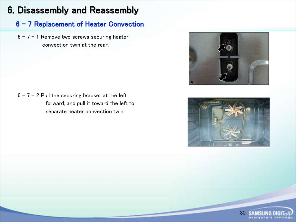
6. Disassembly and Reassembly6 - 7 Replacement of Heater Convection
6 - 7 - 1 Remove two screws securing heater
convection twin at the rear.
6 - 7 - 2 Pull the securing bracket at the left
forward, and pull it toward the left to
separate heater convection twin.
30
31.
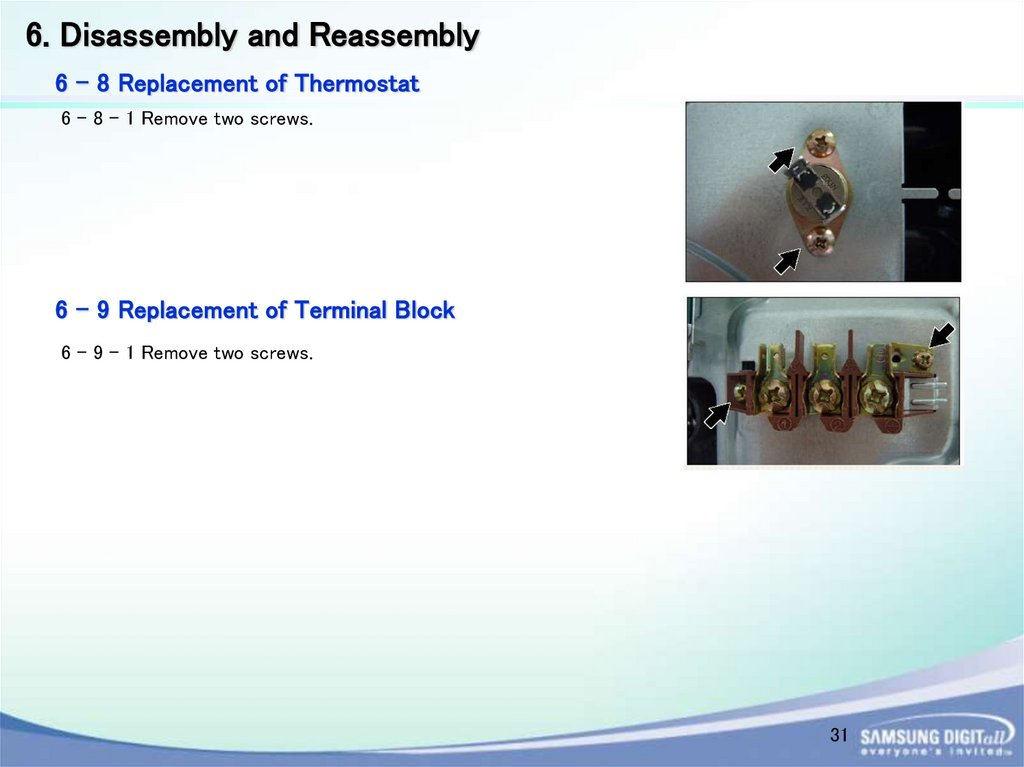
6. Disassembly and Reassembly6 - 8 Replacement of Thermostat
6 - 8 - 1 Remove two screws.
6 - 9 Replacement of Terminal Block
6 - 9 - 1 Remove two screws.
31
32.
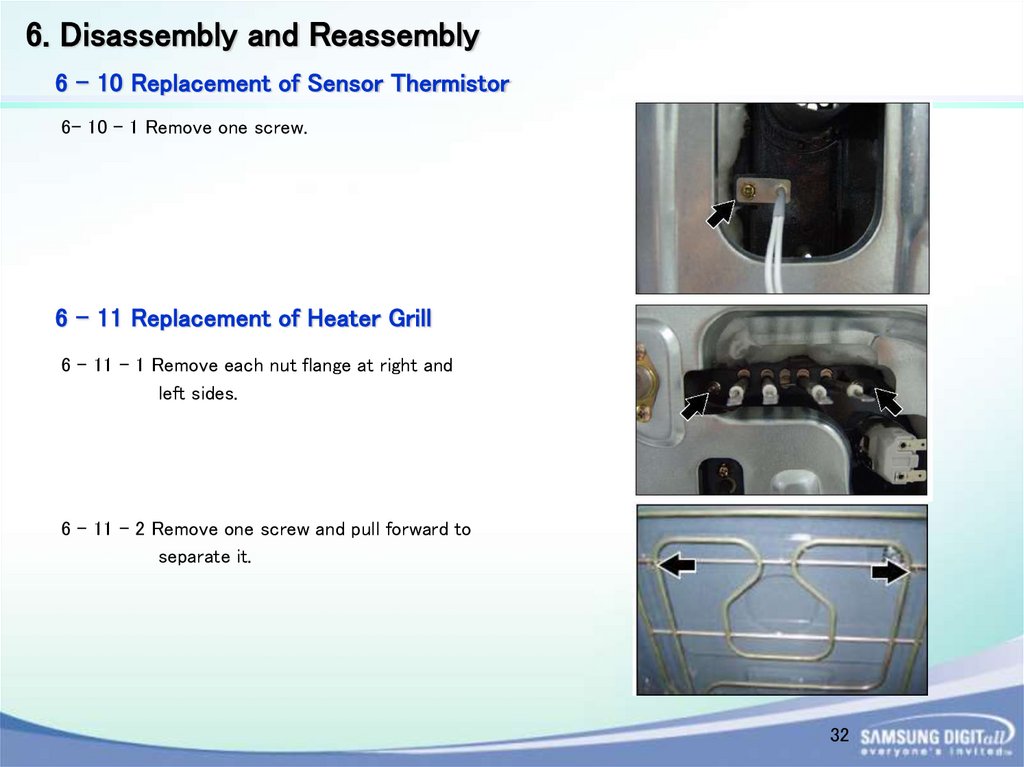
6. Disassembly and Reassembly6 - 10 Replacement of Sensor Thermistor
6- 10 - 1 Remove one screw.
6 - 11 Replacement of Heater Grill
6 - 11 - 1 Remove each nut flange at right and
left sides.
6 - 11 - 2 Remove one screw and pull forward to
separate it.
32
33.
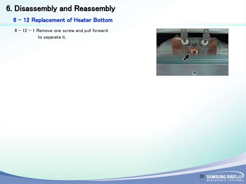
6. Disassembly and Reassembly6 - 12 Replacement of Heater Bottom
6 - 12 - 1 Remove one screw and pull forward
to separate it.
33
34.
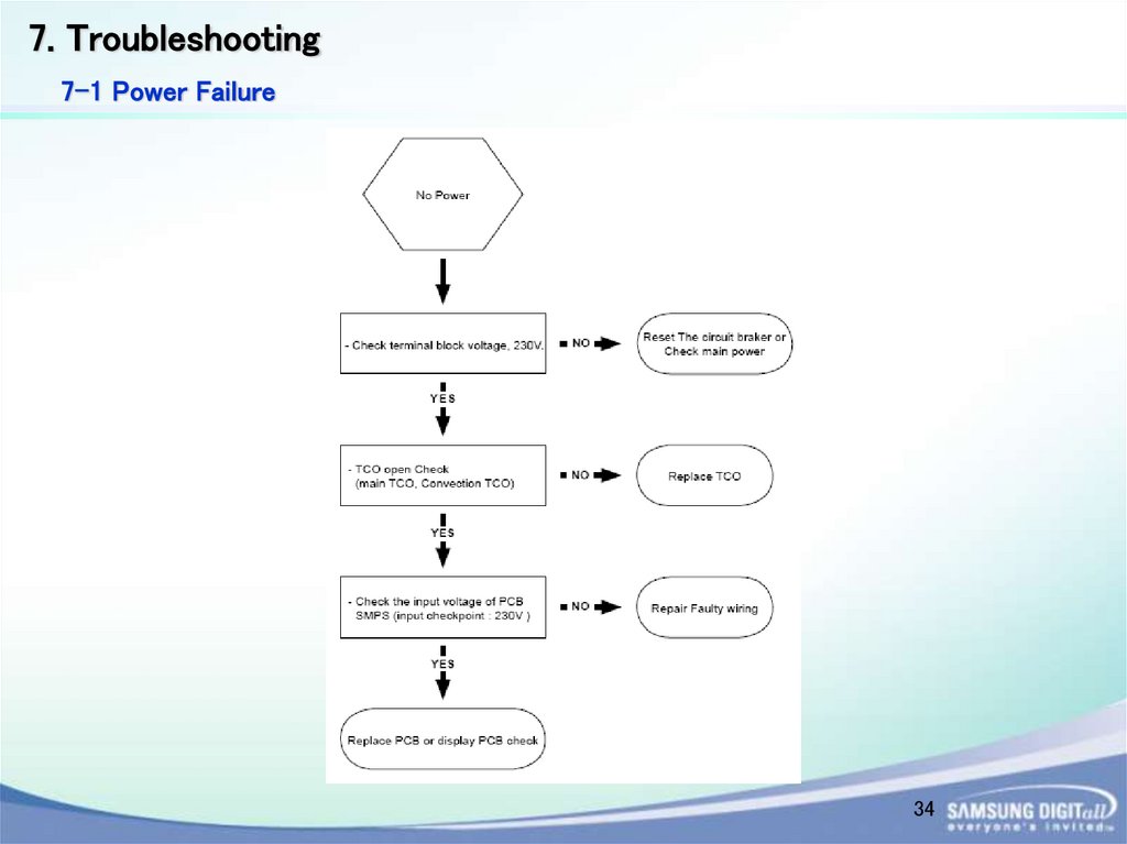
7. Troubleshooting7-1 Power Failure
34
35.
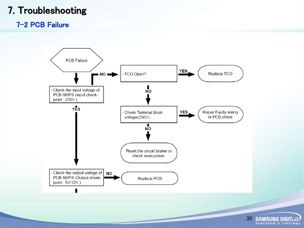
7. Troubleshooting7-2 PCB Failure
35
36.
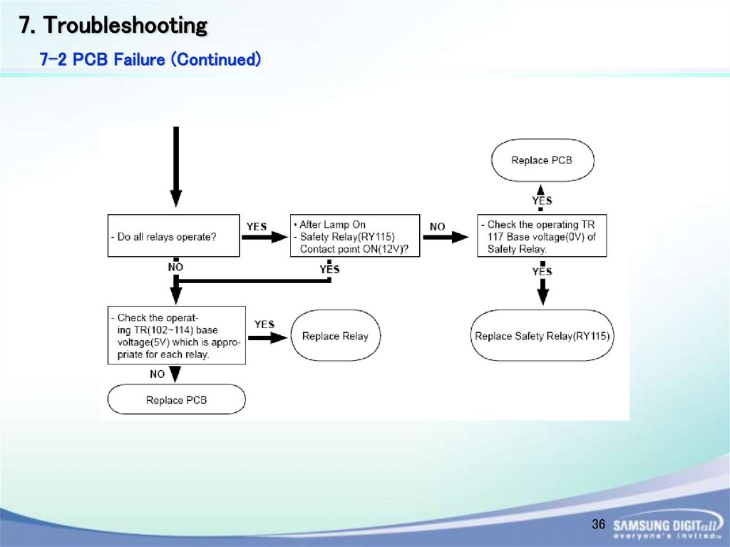
7. Troubleshooting7-2 PCB Failure (Continued)
36
37.
7. Troubleshooting7-3 Failure of heating elements
37
38.
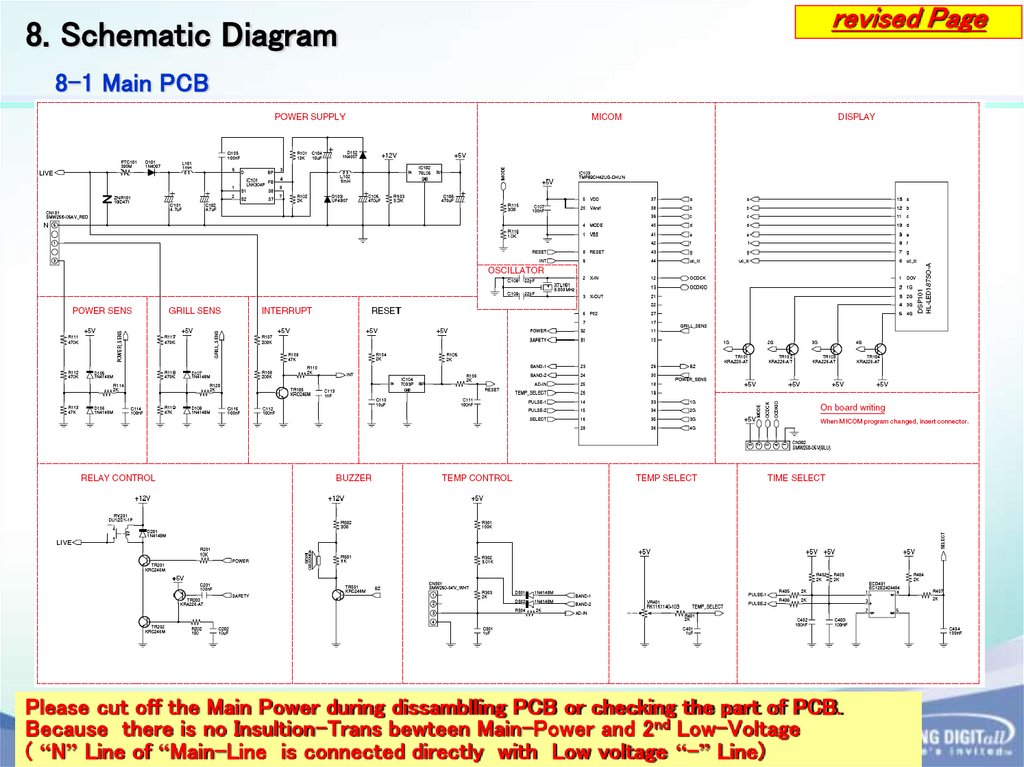
8. Schematic Diagramrevised Page
8-1 Main PCB
Please cut off the Main Power during dissamblling PCB or checking the part of PCB.
Because there is no Insultion-Trans bewteen Main-Power and 2nd Low-Voltage 38
( “N” Line of “Main-Line is connected directly with Low voltage “-” Line)
39.
8. Schematic Diagramrevised Page
8-2 SMPS Diagram
39
40.
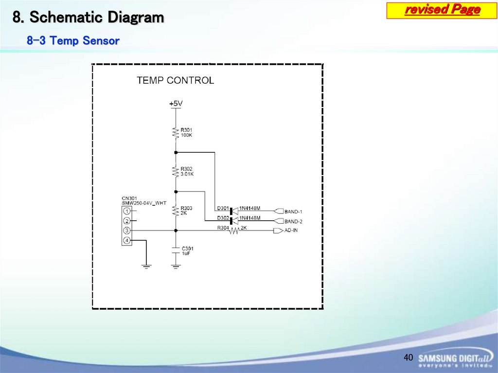
8. Schematic Diagramrevised Page
8-3 Temp Sensor
40
41.
8. Schematic Diagramrevised Page
8-4 Relay Operation Diagram
41
42.
9. Wiring Diagramrevised Page
42
43.
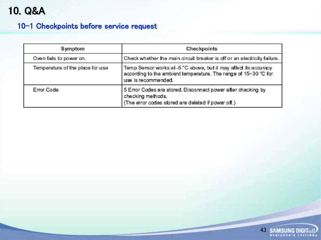
10. Q&A10-1 Checkpoints before service request
43
44.
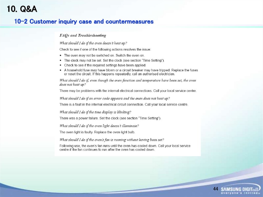
10. Q&A10-2 Customer inquiry case and countermeasures
44
45.
Thank You45