


 Электроника
Похожие презентации:


Development 3 Group Lab 1 (VD)
1.
대 외 비보존기한 3 년
2343BW / 2343NW
Training Manual
Development 3 Group
Lab 1 (VD)
2.
ContentsProduct Overview
Circuit Description
Assembly and Disassembly
Troubleshooting
How to Execute Code
Etc.
3.
1. Product Overview(Product Features)
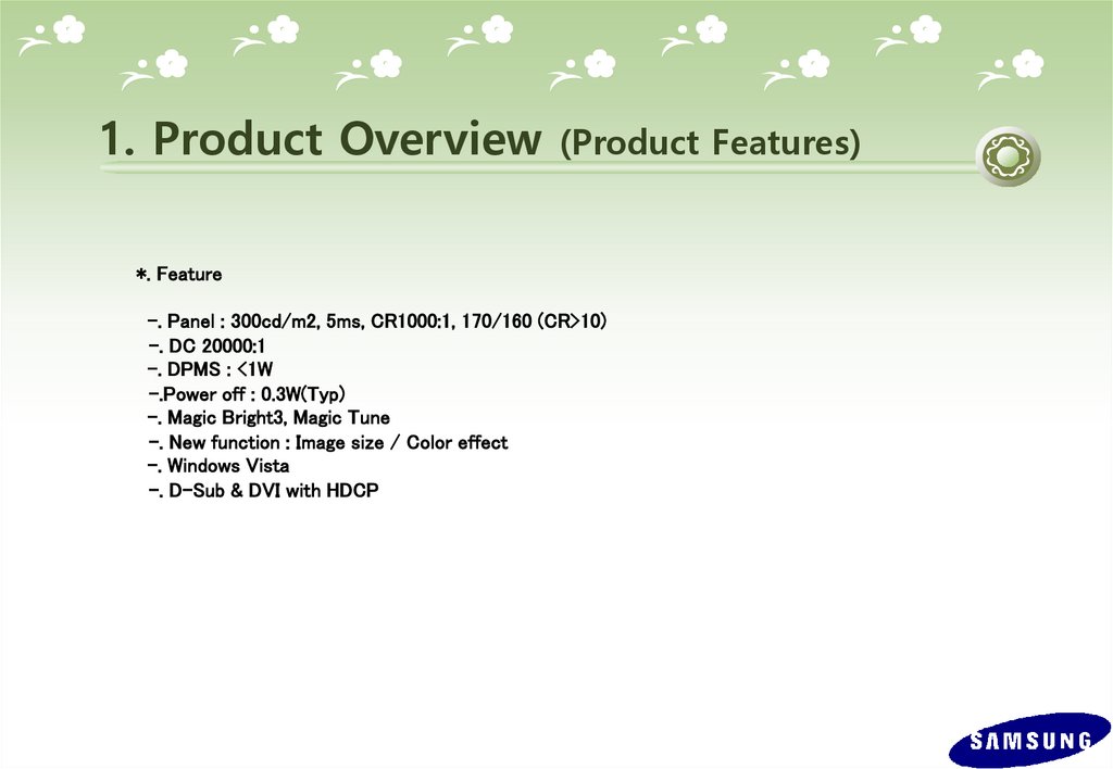
*. Feature
-. Panel : 300cd/m2, 5ms, CR1000:1, 170/160 (CR>10)
-. DC 20000:1
-. DPMS : <1W
-.Power off : 0.3W(Typ)
-. Magic Bright3, Magic Tune
-. New function : Image size / Color effect
-. Windows Vista
-. D-Sub & DVI with HDCP
4.
1. Product Overview(Product Specification)
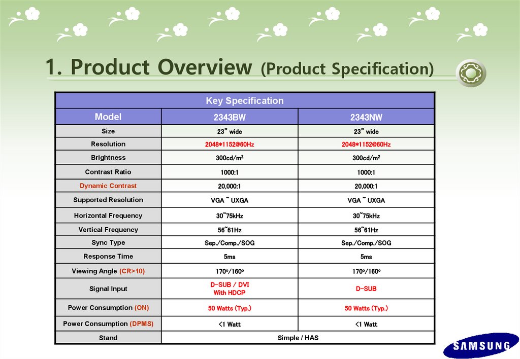
Key Specification
Model
2343BW
2343NW
Size
23” wide
23” wide
Resolution
2048*1152@60Hz
2048*1152@60Hz
Brightness
300cd/m2
300cd/m2
Contrast Ratio
1000:1
1000:1
Dynamic Contrast
20,000:1
20,000:1
Supported Resolution
VGA ~ UXGA
VGA ~ UXGA
Horizontal Frequency
30~75kHz
30~75kHz
Vertical Frequency
56~61Hz
56~61Hz
Sync Type
Sep./Comp./SOG
Sep./Comp./SOG
Response Time
5ms
5ms
Viewing Angle (CR>10)
170o/160o
170o/160o
Signal Input
D-SUB / DVI
With HDCP
D-SUB
Power Consumption (ON)
50 Watts (Typ.)
50 Watts (Typ.)
Power Consumption (DPMS)
<1 Watt
<1 Watt
Stand
Simple / HAS
5.
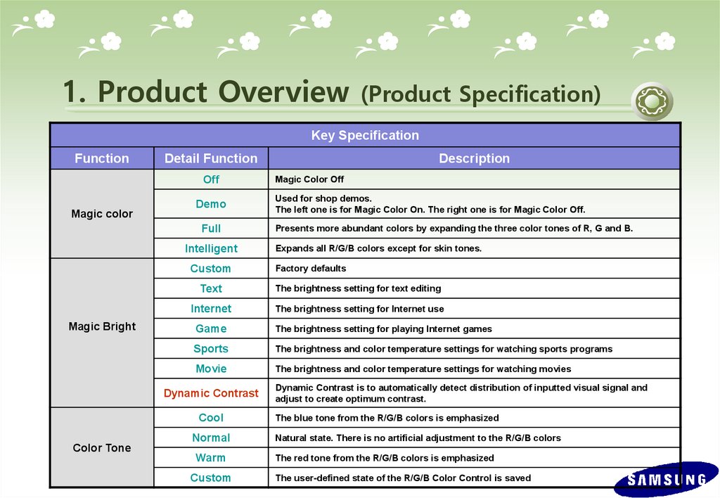
1. Product Overview(Product Specification)
Key Specification
Function
Detail Function
Off
Magic color
Demo
Full
Intelligent
Custom
Magic Bright
Magic Color Off
Used for shop demos.
The left one is for Magic Color On. The right one is for Magic Color Off.
Presents more abundant colors by expanding the three color tones of R, G and B.
Expands all R/G/B colors except for skin tones.
Factory defaults
Text
The brightness setting for text editing
Internet
The brightness setting for Internet use
Game
The brightness setting for playing Internet games
Sports
The brightness and color temperature settings for watching sports programs
Movie
The brightness and color temperature settings for watching movies
Dynamic Contrast
Cool
Color Tone
Description
Normal
Warm
Custom
Dynamic Contrast is to automatically detect distribution of inputted visual signal and
adjust to create optimum contrast.
The blue tone from the R/G/B colors is emphasized
Natural state. There is no artificial adjustment to the R/G/B colors
The red tone from the R/G/B colors is emphasized
The user-defined state of the R/G/B Color Control is saved
6.
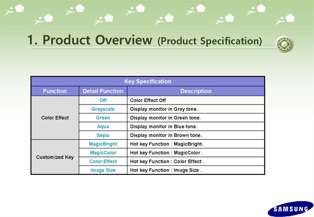
1. Product Overview(Product Specification)
Key Specification
Function
Detail Function
Off
Grayscale
Color Effect
Customized Key
Description
Color Effect Off
Display monitor in Gray tone.
Green
Display monitor in Green tone.
Aqua
Display monitor in Blue tone.
Sepia
Display monitor in Brown tone.
MagicBright
Hot key Function : MagicBright.
MagicColor
Hot key Function : MagicColor .
Color Effect
Hot key Function : Color Effect .
Image Size
Hot key Function : Image Size .
7.
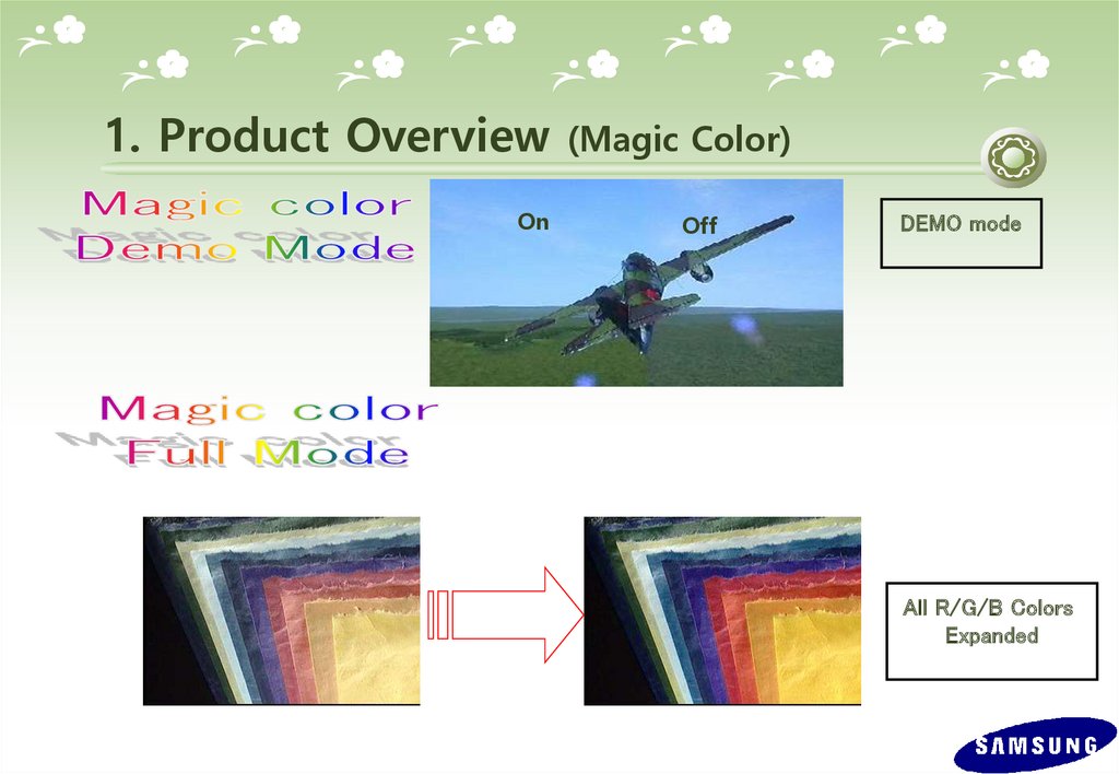
1. Product OverviewOn
(Magic Color)
Off
DEMO mode
All R/G/B Colors
Expanded
8.
1. Product Overview (Magic Color)Except Skin Tone
9.
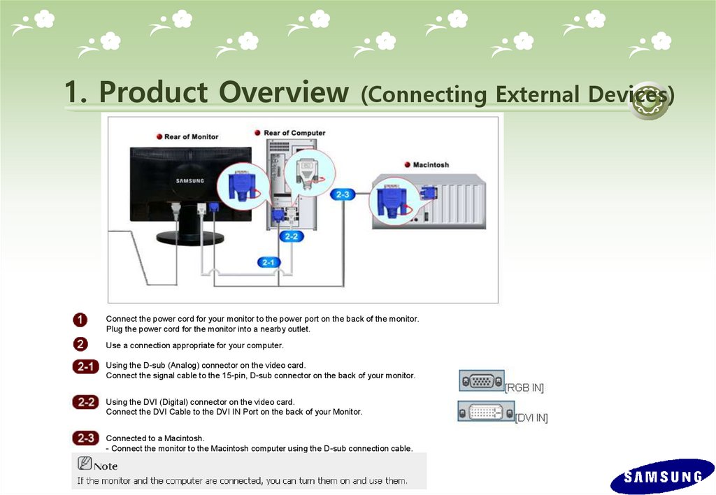
1. Product Overview(Connecting External Devices)
1.
Connect the power cord for your monitor to the power port on the back of the monitor.
Plug the power cord for the monitor into a nearby outlet.
2.
Use a connection appropriate for your computer.
2-1.
Using the D-sub (Analog) connector on the video card.
Connect the signal cable to the 15-pin, D-sub connector on the back of your monitor.
2-2.
Using the DVI (Digital) connector on the video card.
Connect the DVI Cable to the DVI IN Port on the back of your Monitor.
2-3.
Connected to a Macintosh.
- Connect the monitor to the Macintosh computer using the D-sub connection cable.
10.
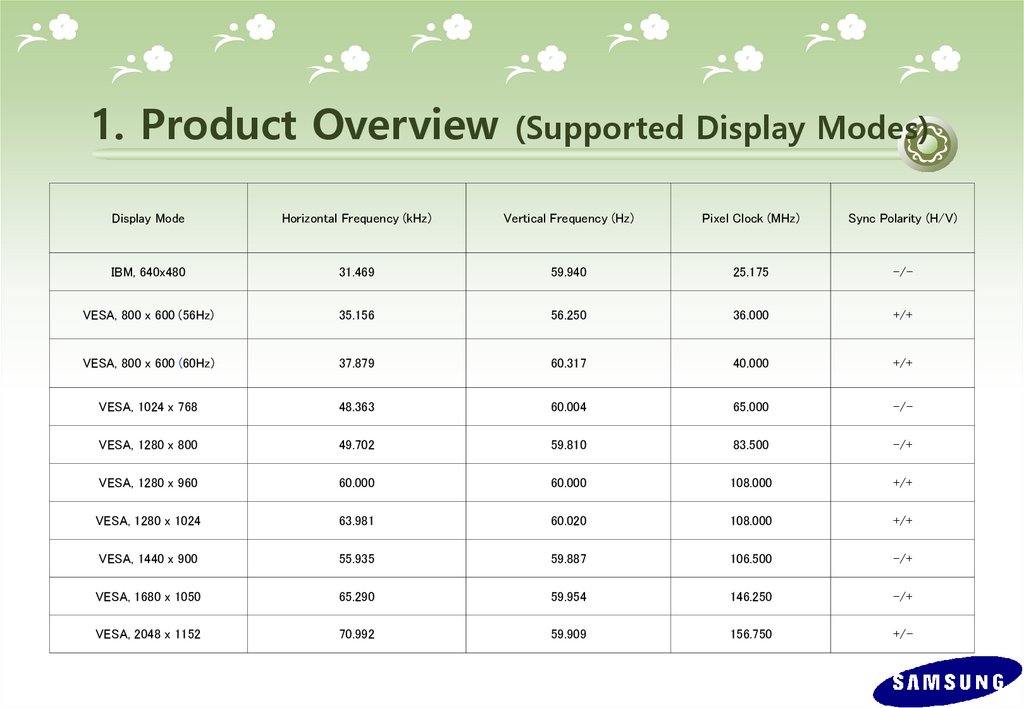
1. Product Overview(Supported Display Modes)
Display Mode
Horizontal Frequency (kHz)
Vertical Frequency (Hz)
Pixel Clock (MHz)
Sync Polarity (H/V)
IBM, 640x480
31.469
59.940
25.175
-/-
VESA, 800 x 600 (56Hz)
35.156
56.250
36.000
+/+
VESA, 800 x 600 (60Hz)
37.879
60.317
40.000
+/+
VESA, 1024 x 768
48.363
60.004
65.000
-/-
VESA, 1280 x 800
49.702
59.810
83.500
-/+
VESA, 1280 x 960
60.000
60.000
108.000
+/+
VESA, 1280 x 1024
63.981
60.020
108.000
+/+
VESA, 1440 x 900
55.935
59.887
106.500
-/+
VESA, 1680 x 1050
65.290
59.954
146.250
-/+
VESA, 2048 x 1152
70.992
59.909
156.750
+/-
11.
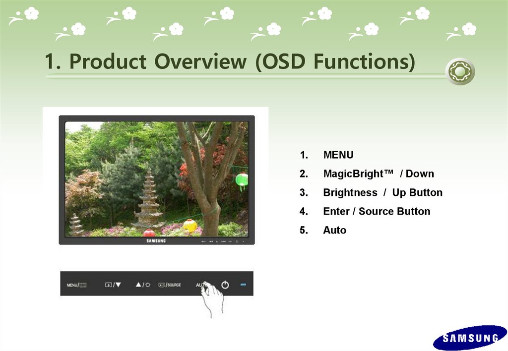
1. Product Overview (OSD Functions)1.
MENU
2.
MagicBright™ / Down
3.
Brightness / Up Button
4.
Enter / Source Button
5.
Auto
12.
1. Product Overview (OSD Functions)(1)
(2)
MENU Button
MagicBright Button
: Open the OSD menu. Use this button to exit the OSD or go to the upper OSD menu.
: Press this button to adjust MagicBright™.
MagicBright™ is a monitor that fits to various user environments such as editing
documents, Internet use and watching movies, etc. It has more than double the bright
ness and screen quality of existing monitors. The dedicated buttons on the front of
the monitor allow users to easily implement six (7) different sets of brightness and
clearness settings that fit the environment
-. Custom
: The Custom mode provides refined brightness and clearness levels.
However, it may not be comfortable on the eyes depending on the user’s preferences.
In this case, adjust the brightness and clearness using the menu.
-. Text
: Text mode provides the same brightness level of general monitors appropriate for text editing.
-. Internet
: Internet mode provides enhanced brightness while maintaining a level of text readability
appropriate to the Internet environment where text and images are combined.
-. Game
: Game mode provides a brightness level appropriate for playing games where there are a lot of
graphics and fast screen switching.
-. Sport
: Sports mode provides a brightness level appropriate for watching sports programs where there is
a lot of movement.
-. Movie
: Movie mode provides excellent brightness and cleanness levels for the entertainment (movies,
DVD, TV, etc.) environment, at the same level as a TV.
-. Dynamic Contrast : Dynamic Contrast is to automatically detect distribution of inputted visual signal and adjust to
create optimum contrast
(3)Brightness Button
: Use this button to adjust the brightness of the screen
13.
1. Product Overview (OSD Functions)(4) Enter/ Source Button : Press this button to select a function and video source..
(5) Auto Button
: If Button is pressed. Auto adjustment function operates automatically.
(Only in analog mode)
(6) Power Button
: Press this button to turn the monitor on or off.
14.
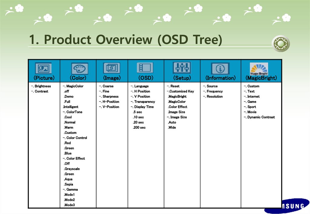
1. Product Overview (OSD Tree)(Picture)
-. Brightness
-. Contrast
(Color)
-. MagicColor
.off
.Demo
.Full
.Intelligent
-. ColorTone
.Cool
.Normal
.Warm
.Custom
-. Color Control
.Red
.Green
.Blue
-. Color Effect
.Off
.Grayscale
.Green
.Aqua
.Sepia
-. Gamma
.Mode1
.Mode2
.Mode3
(Image)
-. Coarse
-. Fine
-. Sharpness
-. H-Position
-. V-Position
(OSD)
-. Language
-. H Position
-. V Position
-. Transparency
-. Display Time
.5 sec
.10 sec
.20 sec
.200 sec
(Setup)
-. Reset
-.Customized Key
.MagicBright
.MagicColor
.Color Effect
.Image Size
-. Image Size
.Auto
.Wide
(Information)
-. Source
-. Frequency
-. Resolution
(MagicBright)
-. Custom
-. Text
-. Internet
-. Game
-. Sport
-. Movie
-. Dynamic Contrast
15.
1. Product Overview (OSD Hidden Key)No
Function
Operating method
Select Brightness from the menu, and then hold down the Enter button
for five (5) seconds while the menu is displayed.
1
User Delete
2
Entering the Set both the brightness and the contrast to ‘0’ on the menu, and then
Service Menu hold down the Enter button for five (5) seconds while the menu is
displayed.
3
Color
Calibration
Select OSD/Language English from the menu, and then hold down the
Enter button for five (5) seconds while the menu is displayed. (The
screen is in 16 gray colors.)
4
Menu Lock
Hold down the Menu button for five (5) seconds
16.
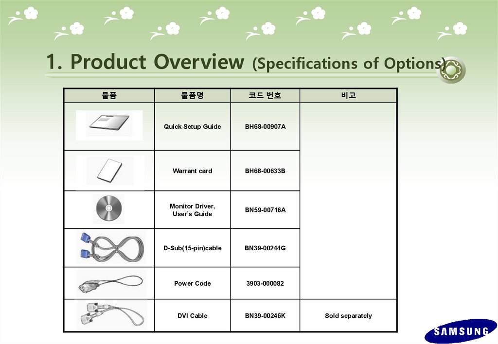
1. Product Overview물품
(Specifications of Options)
물품명
코드 번호
Quick Setup Guide
BH68-00907A
Warrant card
BH68-00633B
Monitor Driver,
User’s Guide
BN59-00716A
D-Sub(15-pin)cable
BN39-00244G
Power Code
3903-000082
DVI Cable
BN39-00246K
비고
Sold separately
17.
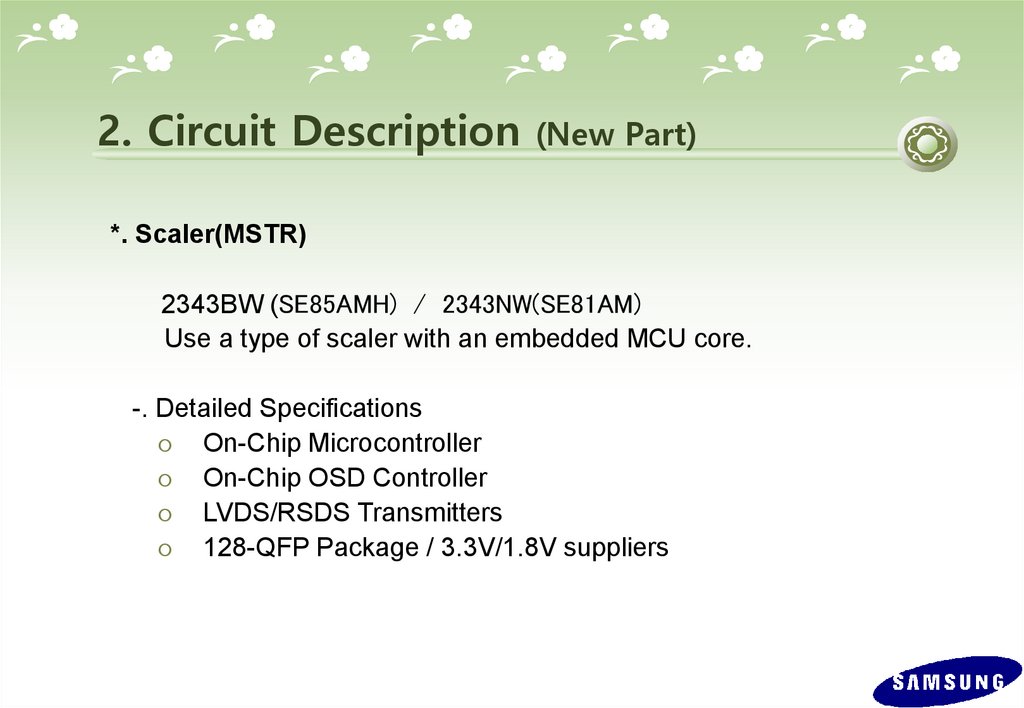
2. Circuit Description(New Part)
*. Scaler(MSTR)
2343BW (SE85AMH) / 2343NW(SE81AM)
Use a type of scaler with an embedded MCU core.
-. Detailed Specifications
On-Chip Microcontroller
On-Chip OSD Controller
LVDS/RSDS Transmitters
128-QFP Package / 3.3V/1.8V suppliers
18.
2. Circuit Description(Product Structure)
1. Panel Part
See
Product Specifications.
2. Main Board Part
Receives external PC analog signals, and then outputs the video
signals to the panel using a Scaler and also outputs the same
signals as external input.
3. IP BOARD
Inverter
+ SMPS BOARD
4. Function Button
Transfers the input signals where the Function button is used to the main board
and displays the LED.
19.
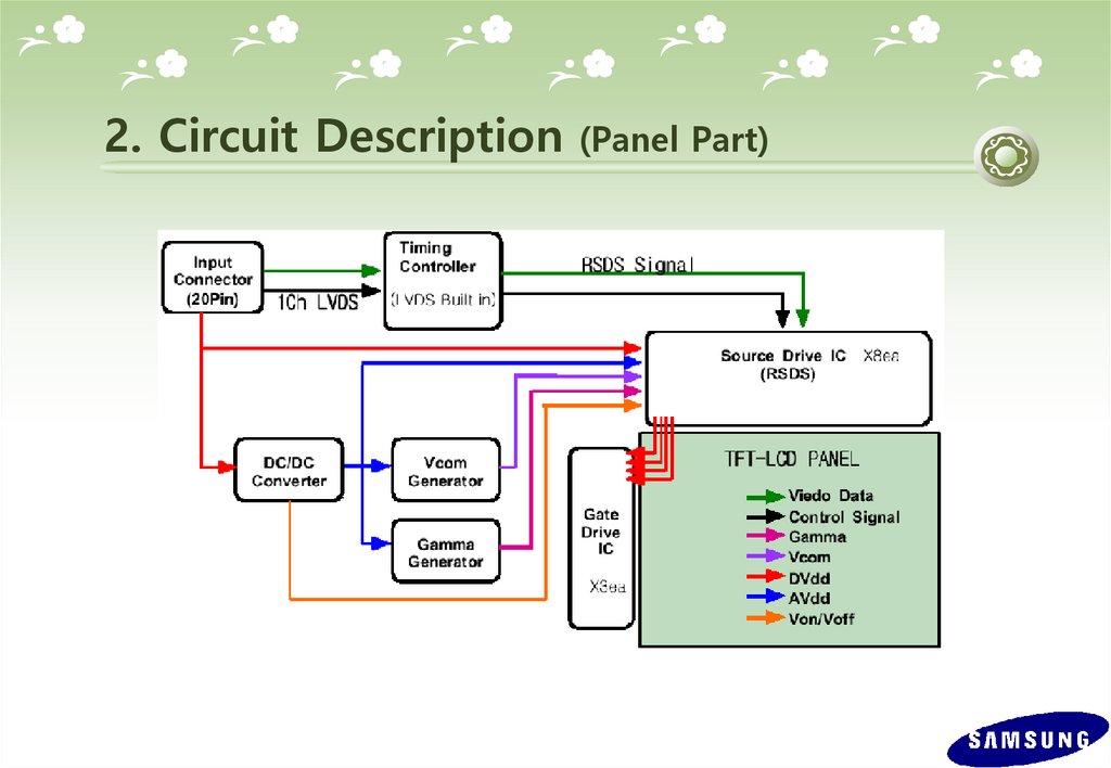
2. Circuit Description(Panel Part)
20.
2. Circuit Description(Panel Part)
* PROTECTION*
LAMP(Inverter) PROTECION
=> The protection is activated if there is no feedback because the lamp connector i
s disconnected or the lamp is cracked.
=> The over voltage protection starts as a lamp protection if the output voltage of t
he inverter transformer is high.
Power Protection
=> All panel protection (OVP/OCP) operates in Auto Recovery mode. When the pa
nel is stopped temporarily due to a protection issue, it powers the panel on again to r
esume the operation after the problem is cleared.
However, as an exception, in the case of a thermal protection issue, the panel can on
ly operate normally if the power is turned off and is fully discharged and turned on ag
ain. This is controlled by a function designed in the power IC.
21.
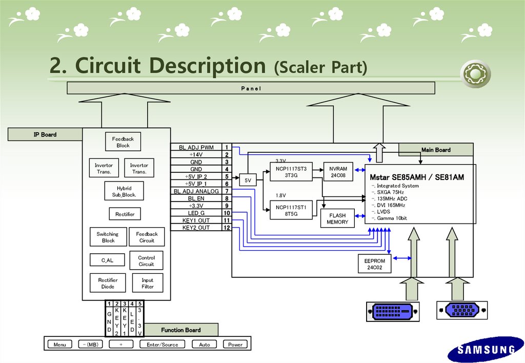
2. Circuit Description(Scaler Part)
Panel
IP Board
Feedback
Block
Invertor
Trans.
Invertor
Trans.
Hybrid
Sub_Block.
Rectifier
Switching
Block
Feedback
Circuit
C_AL
Control
Circuit
Rectifier
Diode
Input
Filter
1 2
K
G
E
N
Y
D
2
Menu
- (MB)
3
K
E
Y
1
+
4 5
3
L
.
E
3
D
V
BL_ADJ_PWM
1
+14V
2
GND
3
GND
4
+5V_IP_2
5
+5V_IP_1
6
BL_ADJ_ANALOG 7
BL_EN
8
+3.3V
9
LED_G
10
KEY1_OUT
11
KEY2_OUT
12
Main Board
5V
3.3V
NCP1117ST3
3T3G
NVRAM
24C08
1.8V
NCP1117ST1
8T5G
FLASH
MEMORY
Mstar SE85AMH / SE81AM
-.
-.
-.
-.
-.
-.
Integrated System
SXGA 75Hz
135MHz ADC
DVI 165MHz
LVDS
Gamma 10bit
EEPROM
24C02
Function Board
Enter/Source
Auto
Power
22.
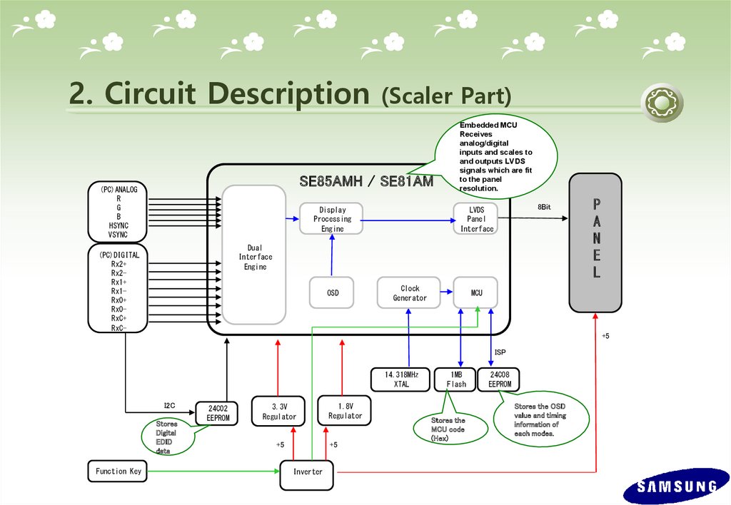
2. Circuit Description(Scaler Part)
SE85AMH / SE81AM
(PC)ANALOG
R
G
B
HSYNC
VSYNC
Display
Processing
Engine
Embedded MCU
Receives
analog/digital
inputs and scales to
and outputs LVDS
signals which are fit
to the panel
resolution.
8Bit
LVDS
Panel
Interface
Dual
Interface
Engine
(PC)DIGITAL
Rx2+
Rx2Rx1+
Rx1Rx0+
Rx0RxC+
RxC-
OSD
Clock
Generator
P
A
N
E
L
MCU
+5
ISP
14.318MHz
XTAL
I2C
Stores
Digital
EDID
data
Function Key
24C02
EEPROM
3.3V
Regulator
+5
1.8V
Regulator
+5
Inverter
1MB
Flash
Stores the
MCU code
(Hex)
24C08
EEPROM
Stores the OSD
value and timing
information of
each modes.
23.
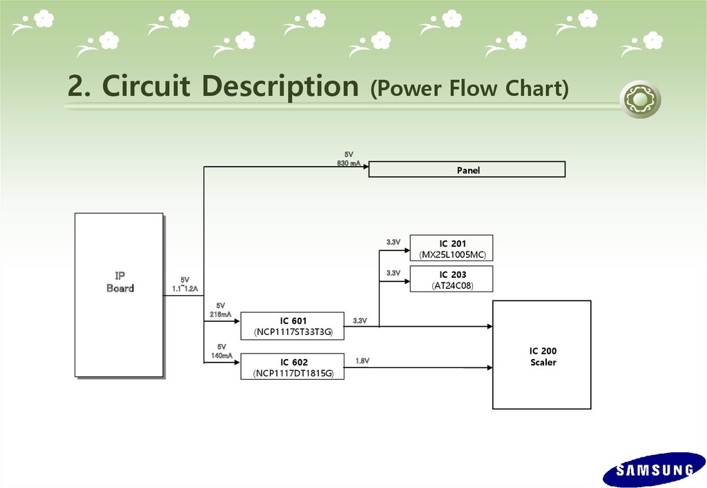
2. Circuit Description(Power Flow Chart)
5V
830 mA
IP
Board
5V
1.1~1.2A
5V
216mA
5V
140mA
IC 601
(NCP1117ST33T3G)
IC 602
(NCP1117DT1815G)
Panel
3.3V
IC 201
(MX25L1005MC)
3.3V
IC 203
(AT24C08)
3.3V
1.8V
IC 200
Scaler
24.
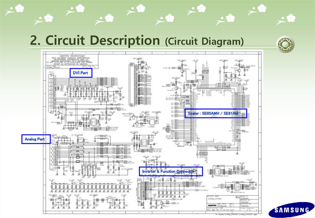
2. Circuit Description(Circuit Diagram)
DVI Part
Scaler : SE85AMH / SE81AM
Analog Part
Inverter & Function Connector
25.
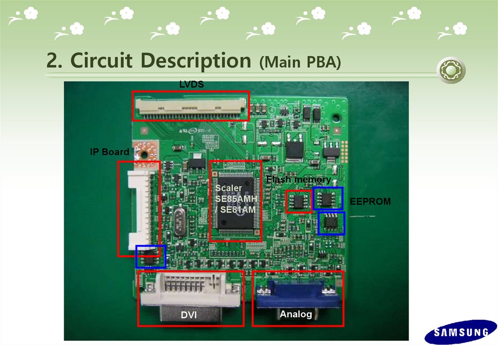
2. Circuit Description(Main PBA)
LVDS
IP Board
Scaler
SE85AMH
/ SE81AM
DVI
Flash memory
EEPROM
Analog
26.
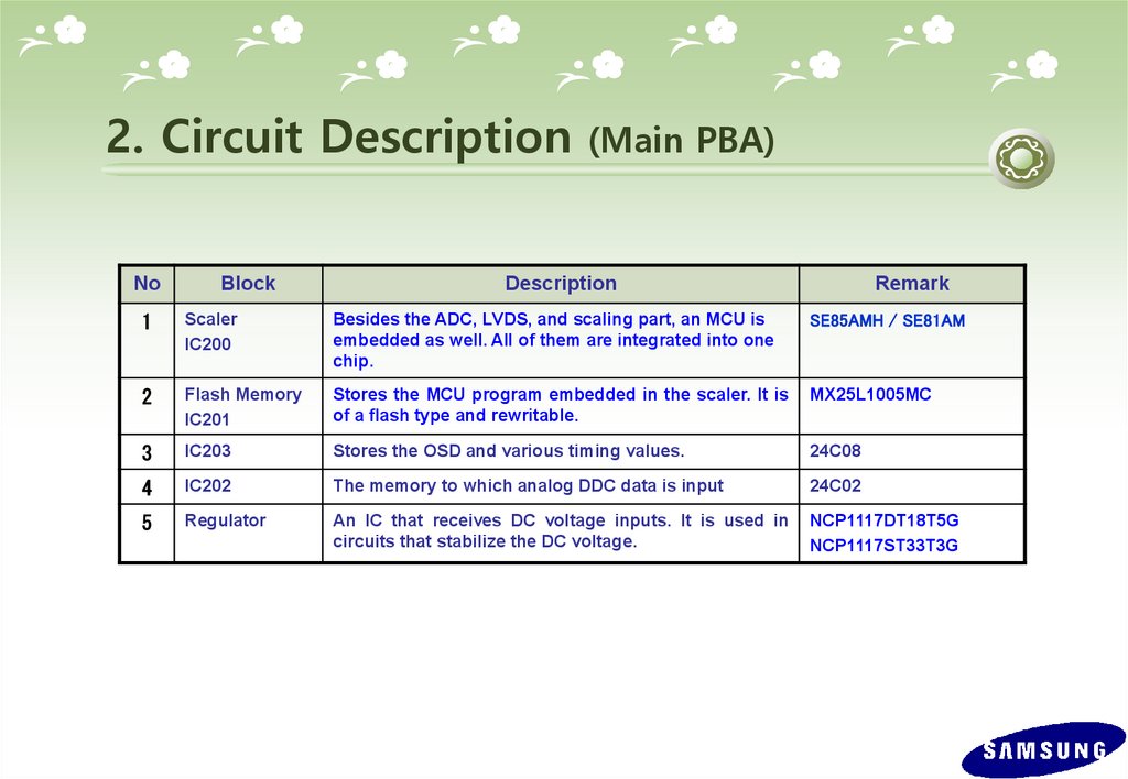
2. Circuit DescriptionNo
Block
(Main PBA)
Description
Remark
1
Scaler
IC200
Besides the ADC, LVDS, and scaling part, an MCU is
embedded as well. All of them are integrated into one
chip.
SE85AMH / SE81AM
2
Flash Memory
IC201
Stores the MCU program embedded in the scaler. It is
of a flash type and rewritable.
MX25L1005MC
3
IC203
Stores the OSD and various timing values.
24C08
4
IC202
The memory to which analog DDC data is input
24C02
5
Regulator
An IC that receives DC voltage inputs. It is used in
circuits that stabilize the DC voltage.
NCP1117DT18T5G
NCP1117ST33T3G
27.
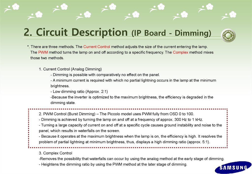
2. Circuit Description(IP Board - Dimming)
*. There are three methods. The Current Control method adjusts the size of the current entering the lamp.
The PWM method turns the lamp on and off according to a specific frequency. The Complex method mixes
those two methods.
1. Current Control (Analog Dimming)
- Dimming is possible with comparatively no effect on the panel.
- A minimum current is required with which no partial lightning occurs in the lamp at the minimum
brightness.
- Low dimming ratio (Approx. 2:1)
-Because the inverter is optimized to the maximum brightness, the efficiency is degraded in the
dimming state.
2. PWM Control (Burst Dimming) – The Piccolo model uses PWM fully from OSD 0 to 100.
- Dimming is achieved by turning the lamp on and off at a frequency of approx. 300 Hz to 1 kHz.
- Turning a large capacity of current on and off at a specific cycle causes ground instability and noise to the
panel, which results in waterfalls on the screen.
- Because it operates at the maximum brightness when the lamp is on, the efficiency is high. It resolves the
problem of partial lightning at minimum brightness, thus, displays a high dimming ratio (approx. 5:1).
3. Complex Control
-Removes the possibility that waterfalls can occur by using the analog method at the early stage of dimming.
- Heightens the dimming ratio by using the PWM method at the later stage of dimming.
28.
2. Circuit Description(IP Board)
SMPS Part
LIN E F Iof
LTEa Rline
, X -filter,
C A P ,an XConsists
CAP,
and
a
Y-CAP.
Y - C A P 으로 구성
P O W E R TR A N S F O R M E R ,
Consists of a power transform
Fer
E T로
and구성
an FET.
S w itc h in g B LO C K
D IO D E , IN D U C TO R ,
Consists of a diode, an induct
Rectification Part
정류부
C A P A Cor,
IT Oand
R 로a 구성
capacitor.
In p ut F ilte r B LO C K
13V out
5V out
D C /A C
IN V E R T E R
M A IN
A /D B O A R D
1 5 " 2 L am p : F S D M 0 3 6 5
Control
Feedback
PConsists
H O TO C OofU Pa LE
R,
photocoupler
an
1 7 ",1 9 "
Circuit
Circuit
d a TL430.
TL43
0로 구성
: N C P 1200
29.
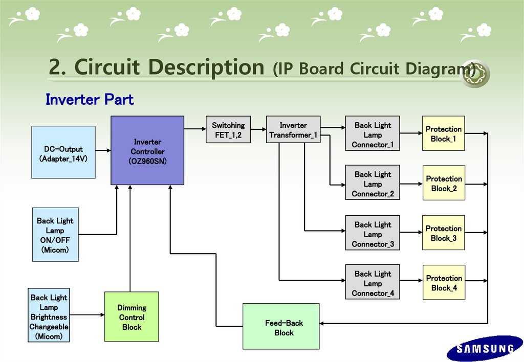
2. Circuit Description(IP Board Circuit Diagram)
Inverter Part
DC-Output
(Adapter_14V)
Inverter
Controller
(OZ960SN)
Switching
FET_1,2
Inverter
Transformer_1
Back Light
Lamp
ON/OFF
(Micom)
Back Light
Lamp
Brightness
Changeable
(Micom)
Dimming
Control
Block
Feed-Back
Block
Back Light
Lamp
Connector_1
Protection
Block_1
Back Light
Lamp
Connector_2
Protection
Block_2
Back Light
Lamp
Connector_3
Protection
Block_3
Back Light
Lamp
Connector_4
Protection
Block_4
30.
3. Assembly and Disassembly (SIMPLESTAND)
Caution :
1. Turn the monitor off before beginning the disassembly sequences for this monitor.
2. When disassembling the monitor, do not use any metal tools except for the provided jig.
3. Disassemble the monitor carefully as directed in the following procedures.
Description
1. Place a soft cloth on the table and place the monitor
onto it with the front part facing downwards.
Hold the monitor set with one hand and hold and pull
the stand body backwards with the other hand to
remove the stand body from the monitor set.
(Caution : If you do not tilt the stand and use too
much force to remove it. The connection pin may
break.)
2. Remove the stand body and then remove the two
(2) screws shown in the figure.
Picture Description
31.
3. Assembly and DisassemblyDescription
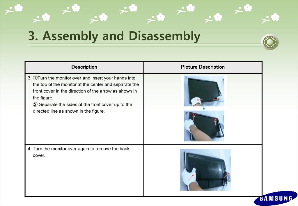
3. ①Turn the monitor over and insert your hands into
the top of the monitor at the center and separate the
front cover in the direction of the arrow as shown in
the figure.
② Separate the sides of the front cover up to the
directed line as shown in the figure.
4. Turn the monitor over again to remove the back
cover.
Picture Description
32.
3. Assembly and DisassemblyDescription
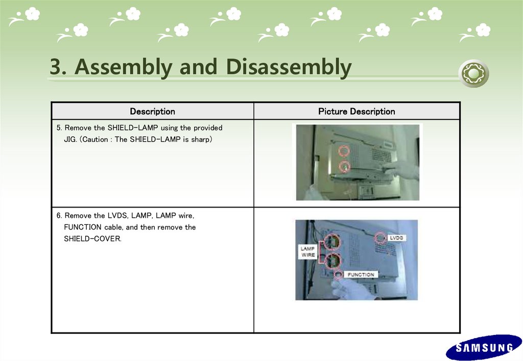
5. Remove the SHIELD-LAMP using the provided
JIG. (Caution : The SHIELD-LAMP is sharp)
6. Remove the LVDS, LAMP, LAMP wire,
FUNCTION cable, and then remove the
SHIELD-COVER.
Picture Description
33.
3. Assembly and DisassemblyDescription
7. Remove the LCD panel.
8. Remove the four (2) screws shown in the figure.
Picture Description
34.
3. Assembly and DisassemblyDescription
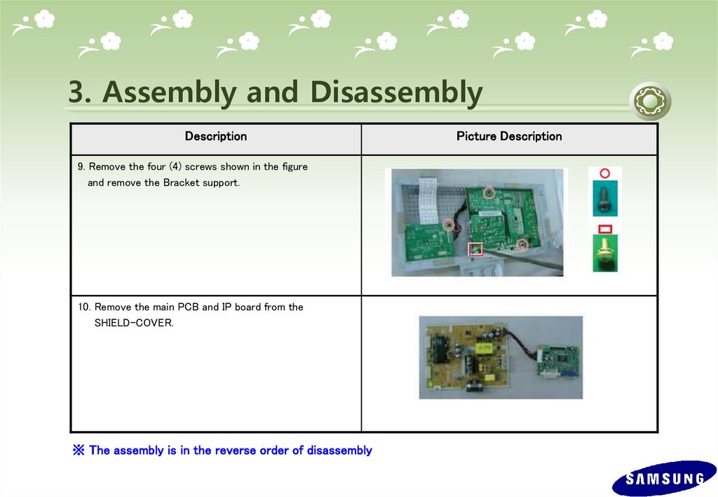
9. Remove the four (4) screws shown in the figure
and remove the Bracket support.
10. Remove the main PCB and IP board from the
SHIELD-COVER.
※ The assembly is in the reverse order of disassembly
Picture Description
35.
3. Assembly and Disassembly (HAS STAND)설명
그림
1. If the Stopper PIN at the back of the stand is not
removed, place a soft cloth on the table and place
the monitor on it, and then hold the monitor set and
remove the Stopper PIN at the back of the stand.
2. Turn the monitor over. Remove the two (2) screws
that hold the stand in place and then remove the
stand.
(Caution : When removing the screws, hold the
stand body with one hand so that the stand does
not fall.)
3. The following steps are the same as steps 2 to 9 for disassembling the SIMPLE stand.
※ The assembly is in the reverse order of disassembly
36.
4. TroubleshootingChecking Before repairing
1. Check the power state and the cable connections.
. Check the connections of the power and signal cables.
. Check whether the function button operates normally.
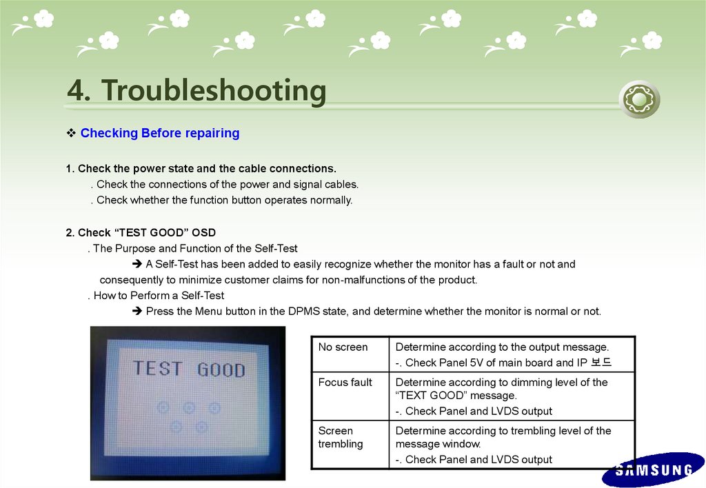
2. Check “TEST GOOD” OSD
. The Purpose and Function of the Self-Test
A Self-Test has been added to easily recognize whether the monitor has a fault or not and
consequently to minimize customer claims for non-malfunctions of the product.
. How to Perform a Self-Test
Press the Menu button in the DPMS state, and determine whether the monitor is normal or not.
No screen
Determine according to the output message.
-. Check Panel 5V of main board and IP 보드
Focus fault
Determine according to dimming level of the
“TEXT GOOD” message.
-. Check Panel and LVDS output
Screen
trembling
Determine according to trembling level of the
message window.
-. Check Panel and LVDS output
37.
4. Troubleshooting*. Other simple diagnostics
No power (No video and Function LED does nor work)
. Check connection Lamp wire, LVDS cable , function cable.
. Disconnect Inverter connector and check 5V and 14V of Ip board connector.
If it does not operate, IP board is inferior goods.
Or BL_EN pin connect to 5V. If panel is not on, Ip board inferior goods.
. Ip board operate normally : Check +5V_Panel signal.
If it operate normally, Panel is inferior goods.
. Panel & Ip board operates normally: Check Main board and Function board.
38.
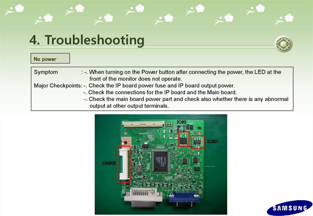
4. TroubleshootingNo power
Symptom
: -. When turning on the Power button after connecting the power, the LED at the
front of the monitor does not operate.
Major Checkpoints: -. Check the IP board power fuse and IP board output power.
-. Check the connections for the IP board and the Main board.
-. Check the main board power part and check also whether there is any abnormal
output at other output terminals.
IC60
2
IC601
CN600
39.
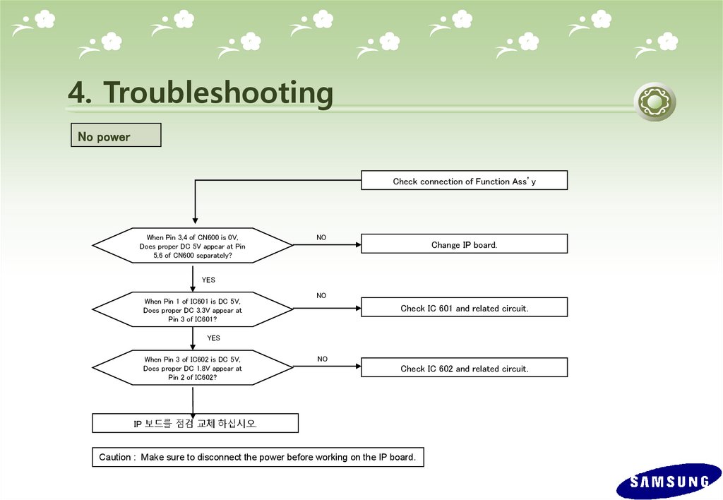
4. TroubleshootingNo power
Check connection of Function Ass’y
When Pin 3,4 of CN600 is 0V,
Does proper DC 5V appear at Pin
5,6 of CN600 separately?
NO
Change IP board.
YES
When Pin 1 of IC601 is DC 5V,
Does proper DC 3.3V appear at
Pin 3 of IC601?
NO
Check IC 601 and related circuit.
YES
When Pin 3 of IC602 is DC 5V,
Does proper DC 1.8V appear at
Pin 2 of IC602?
NO
Check IC 602 and related circuit.
IP 보드를 점검 교체 하십시오.
Caution : Make sure to disconnect the power before working on the IP board.
40.
4. TroubleshootingThe Circuit diagram when the power not turn on
41.
4. TroubleshootingThe Circuit diagram when the power not turn on
42.
4. TroubleshootingNo video (Analog)
Symptom
: -. Though the LED power turns on, the screen is blank when connecting the VGA cable.
Major Checkpoints: -. Check the D-sub connection.
-. Check whether the LVDS cable is connected correctly to the Panel.
-. Check whether the lamp connector of the Panel is connected correctly to the IP board.
CN400
IC200
X201
43.
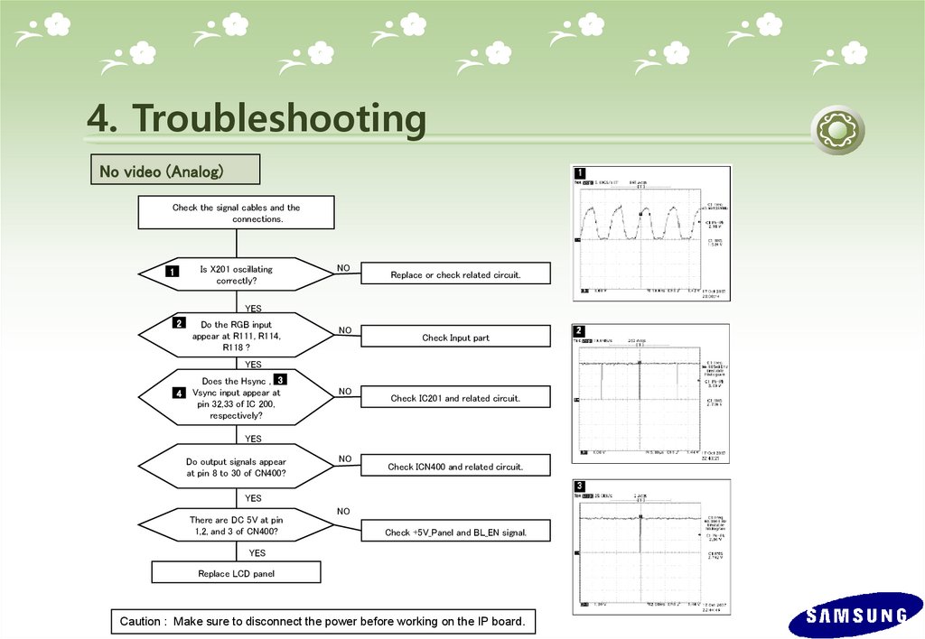
4. TroubleshootingNo video (Analog)
Check the signal cables and the
connections.
Is X201 oscillating
correctly?
1
NO
Replace or check related circuit.
YES
2
Do the RGB input
appear at R111, R114,
R118 ?
NO
Check Input part
YES
4
Does the Hsync , 3
Vsync input appear at
pin 32,33 of IC 200,
respectively?
NO
Check IC201 and related circuit.
YES
Do output signals appear
at pin 8 to 30 of CN400?
NO
Check ICN400 and related circuit.
YES
There are DC 5V at pin
1,2, and 3 of CN400?
NO
Check +5V_Panel and BL_EN signal.
YES
Replace LCD panel
Caution : Make sure to disconnect the power before working on the IP board.
44.
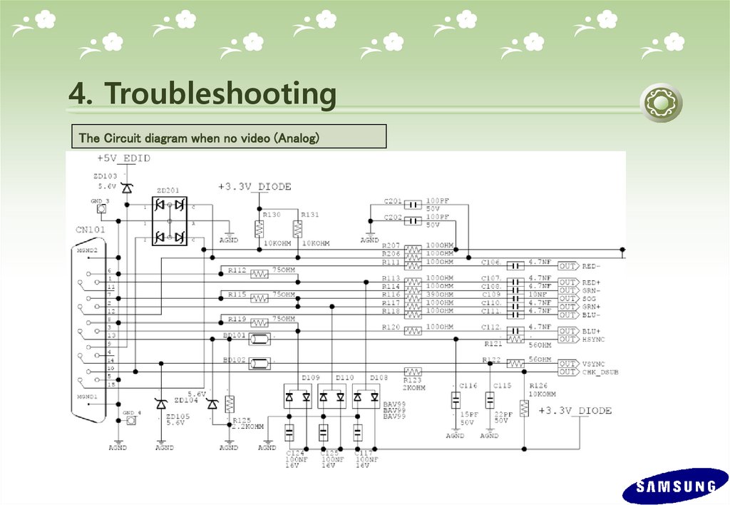
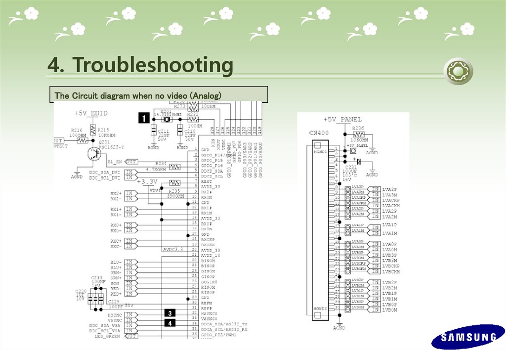
4. TroubleshootingThe Circuit diagram when no video (Analog)
2
45.
4. TroubleshootingThe Circuit diagram when no video (Analog)
1
3
4
46.
4. TroubleshootingNo video (Digital)
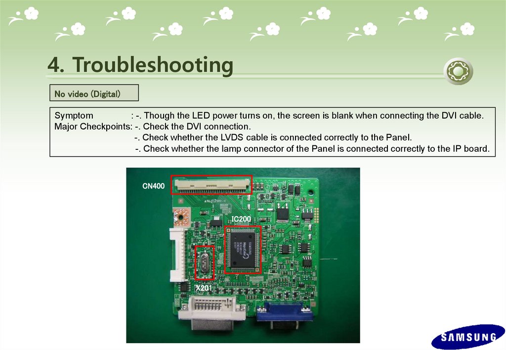
Symptom
: -. Though the LED power turns on, the screen is blank when connecting the DVI cable.
Major Checkpoints: -. Check the DVI connection.
-. Check whether the LVDS cable is connected correctly to the Panel.
-. Check whether the lamp connector of the Panel is connected correctly to the IP board.
CN400
IC200
X201
47.
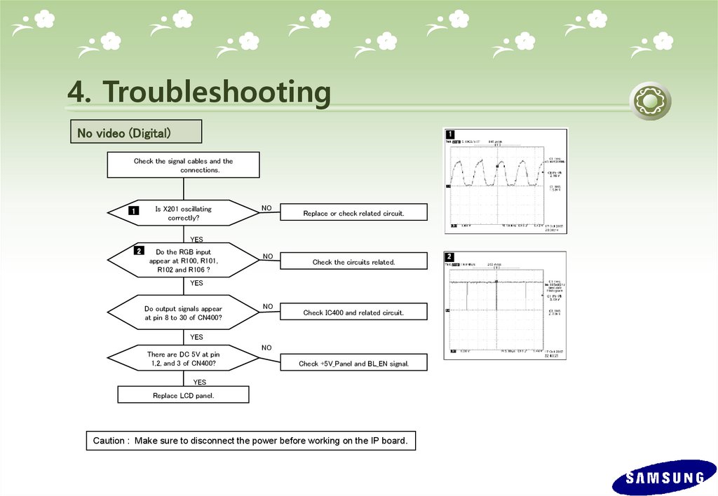
4. TroubleshootingNo video (Digital)
Check the signal cables and the
connections.
Is X201 oscillating
correctly?
1
NO
Replace or check related circuit.
YES
2
Do the RGB input
appear at R100, R101,
R102 and R106 ?
NO
Check the circuits related.
YES
Do output signals appear
at pin 8 to 30 of CN400?
NO
Check IC400 and related circuit.
YES
There are DC 5V at pin
1,2, and 3 of CN400?
NO
Check +5V_Panel and BL_EN signal.
YES
Replace LCD panel.
Caution : Make sure to disconnect the power before working on the IP board.
48.
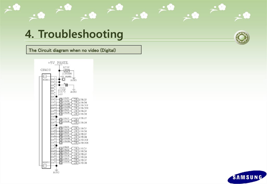
4. TroubleshootingThe Circuit diagram when no video (Digital)
2
49.
4. TroubleshootingThe Circuit diagram when no video (Digital)
50.
4. Troubleshooting*. Check Code version.
-. Enter the service mode, and check MCU code version and checksum.
-.How to enter service mode
Set both the brightness and the contrast to 0.
Hold down the Enter button for five (5) seconds.
The SVC Function OSD will appear.
To exit the SVC Function OSD, you have to turn off the power.
-. Safe Mode.
If the frequency of the input signals is higher than the supported frequency,
Safe mode gives a user a period of time (one (1) minute) to change the video card
settings to a Recommended mode.
51.
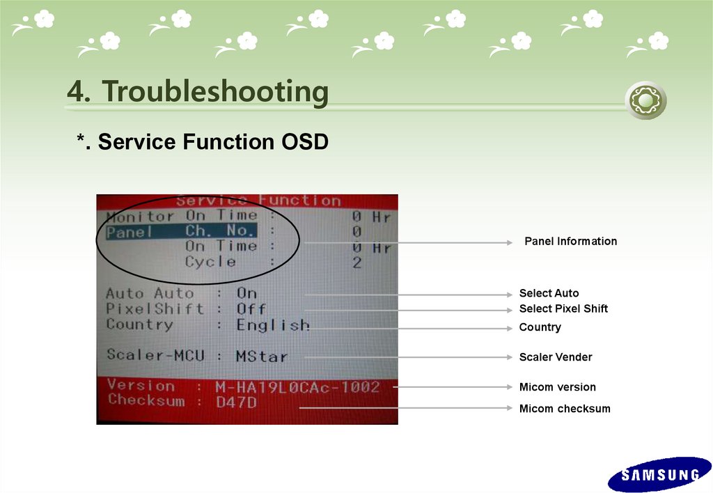
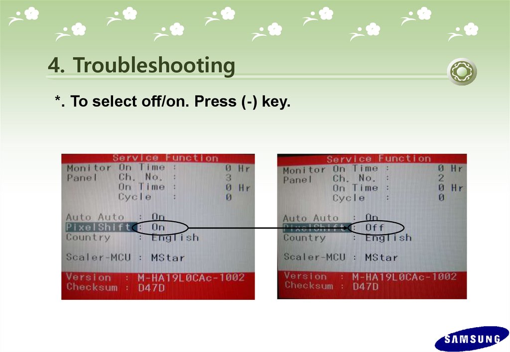
4. Troubleshooting*. Service Function OSD
Panel Information
Select Auto
Select Pixel Shift
Country
Scaler Vender
Micom version
Micom checksum
52.
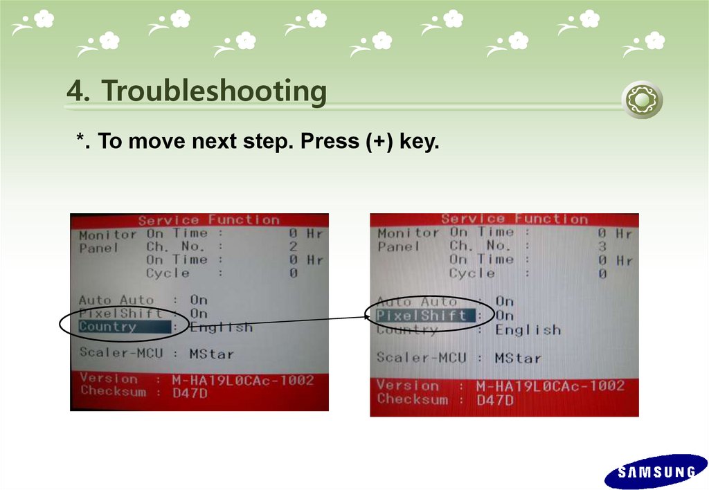
4. Troubleshooting*. To move next step. Press (+) key.
53.
4. Troubleshooting*. To select off/on. Press (-) key.
54.
4. Troubleshooting*. Replace Panel
After replacing the panel, select the Panel item and then hold down the Menu button for
five (5) seconds.
The Ch. No. of the panel will increase. Then, on time and cycle number will be set to 0.
This number will be changed.
55.
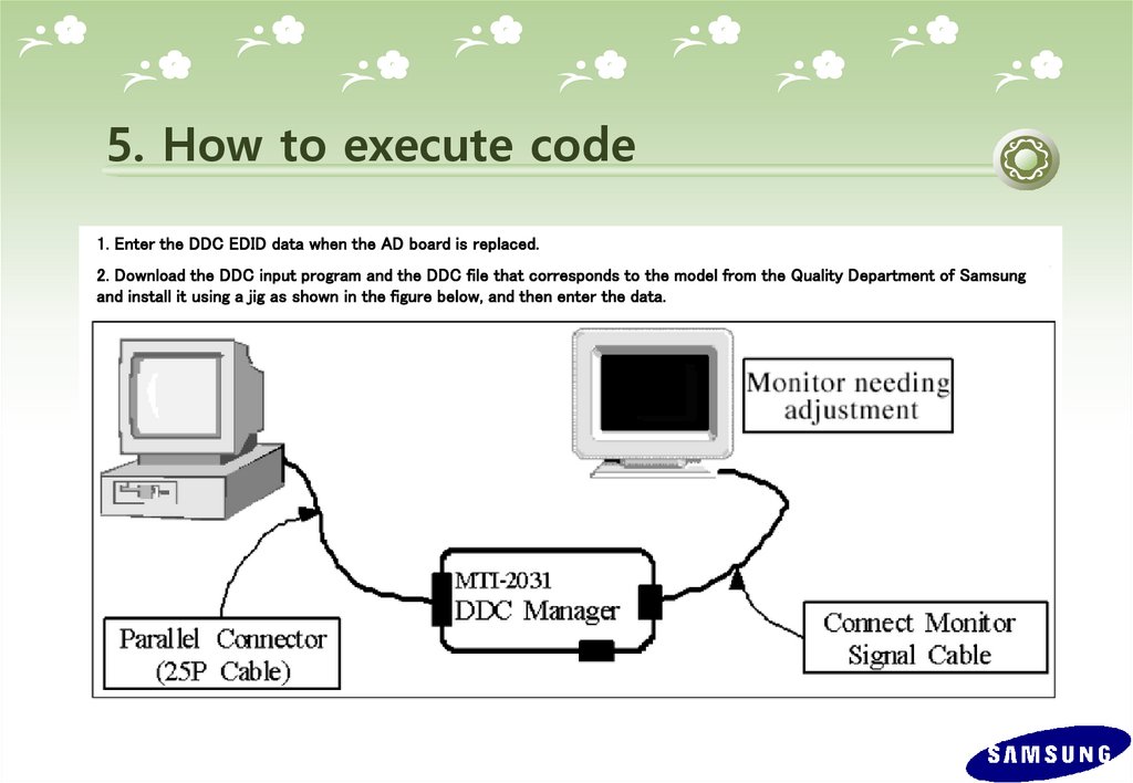
5. How to execute code1. Enter the DDC EDID data when the AD board is replaced.
2. Download the DDC input program and the DDC file that corresponds to the model from the Quality Department of Samsung
and install it using a jig as shown in the figure below, and then enter the data.
56.
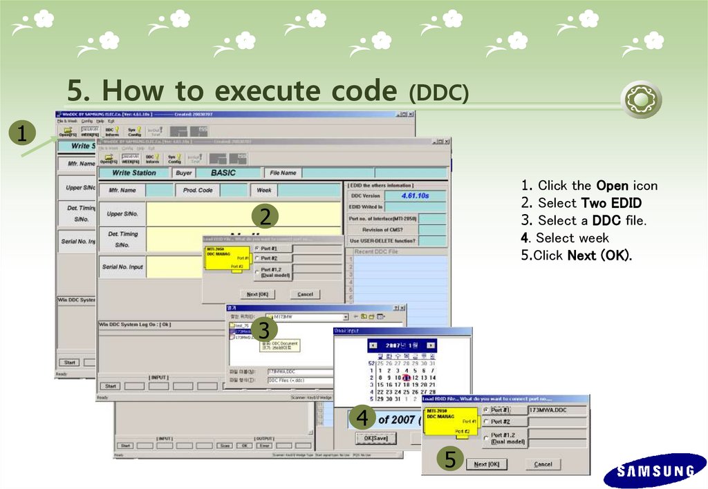
5. How to execute code(DDC)
1
1. Click the Open icon
2. Select Two EDID
3. Select a DDC file.
4. Select week
5.Click Next (OK).
2
3
4
5
57.
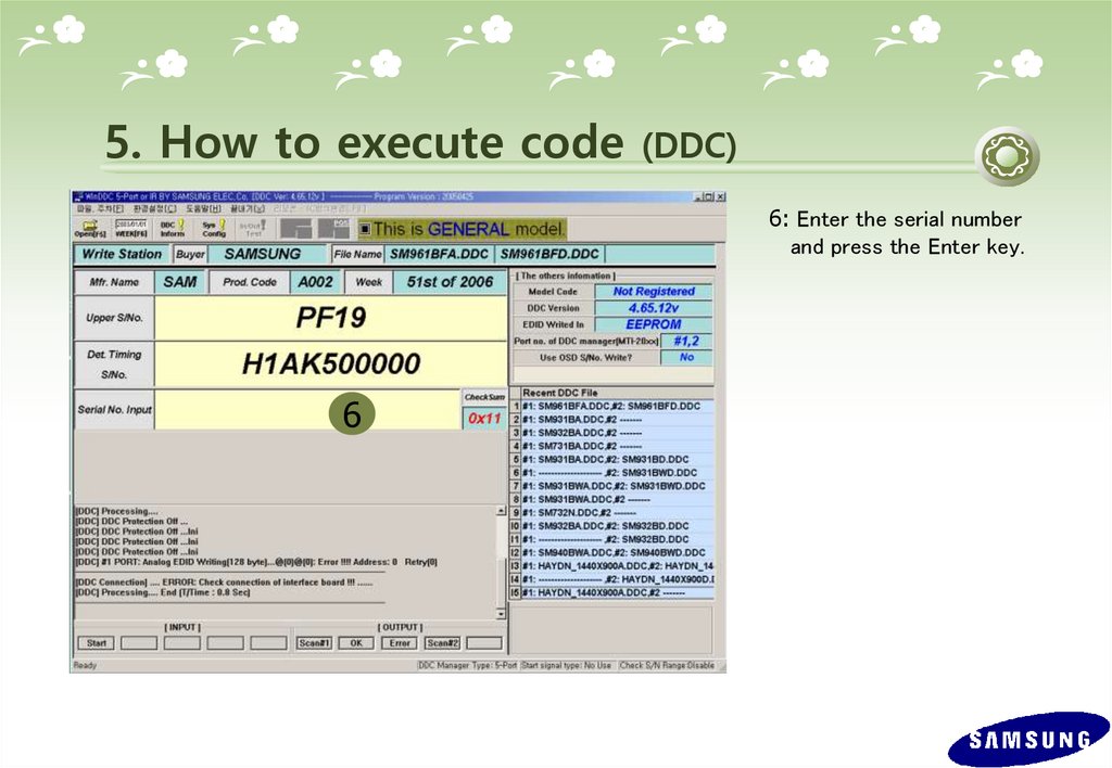
5. How to execute code(DDC)
6: Enter the serial number
and press the Enter key.
6
58.
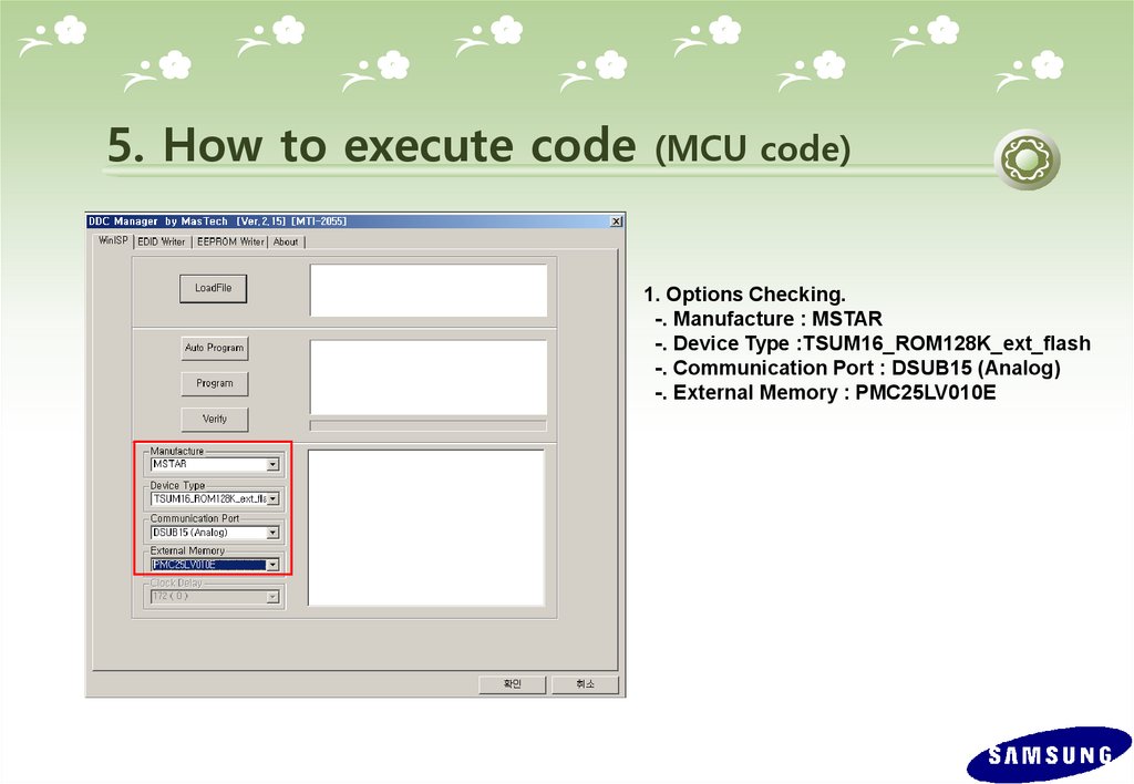
5. How to execute code(MCU code)
1. Options Checking.
-. Manufacture : MSTAR
-. Device Type :TSUM16_ROM128K_ext_flash
-. Communication Port : DSUB15 (Analog)
-. External Memory : PMC25LV010E
59.
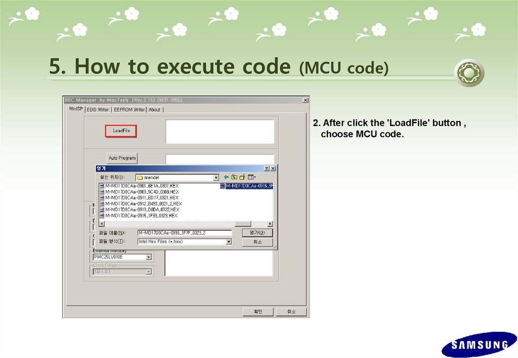
5. How to execute code(MCU code)
2. After click the 'LoadFile' button ,
choose MCU code.
60.
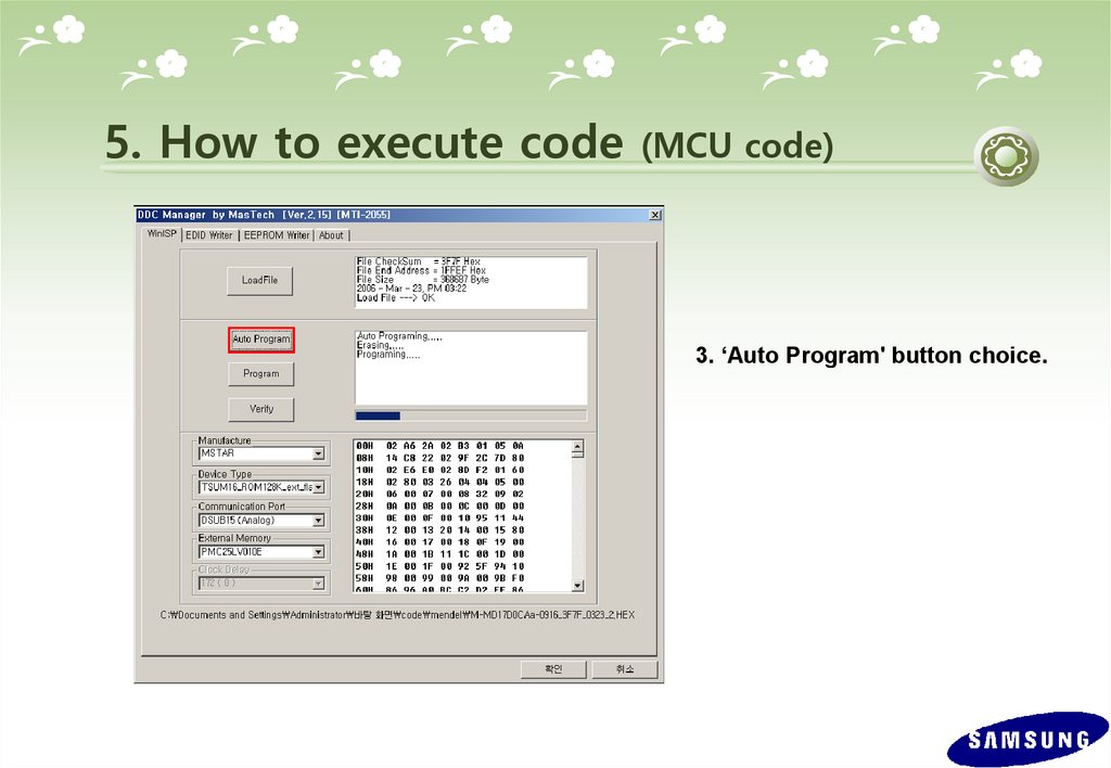
5. How to execute code(MCU code)
3. ‘Auto Program' button choice.
61.
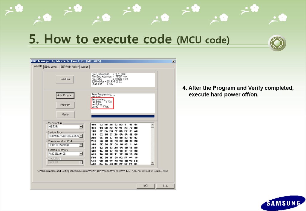
5. How to execute code(MCU code)
4. After the Program and Verify completed,
execute hard power off/on.
62.
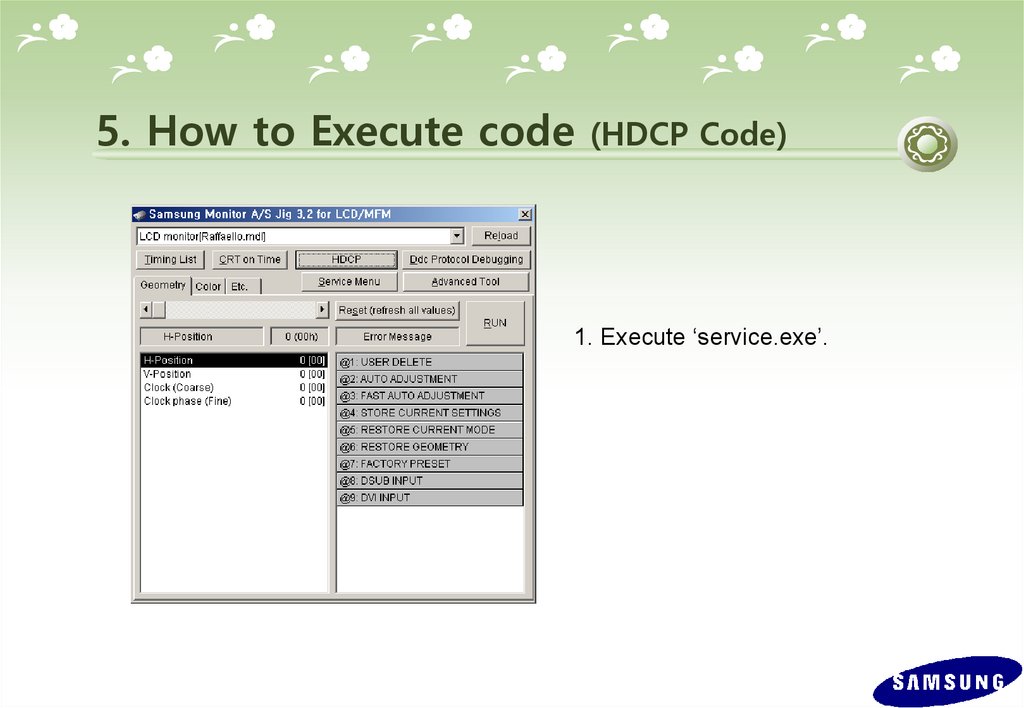
5. How to Execute code(HDCP Code)
1. Execute ‘service.exe’.
63.
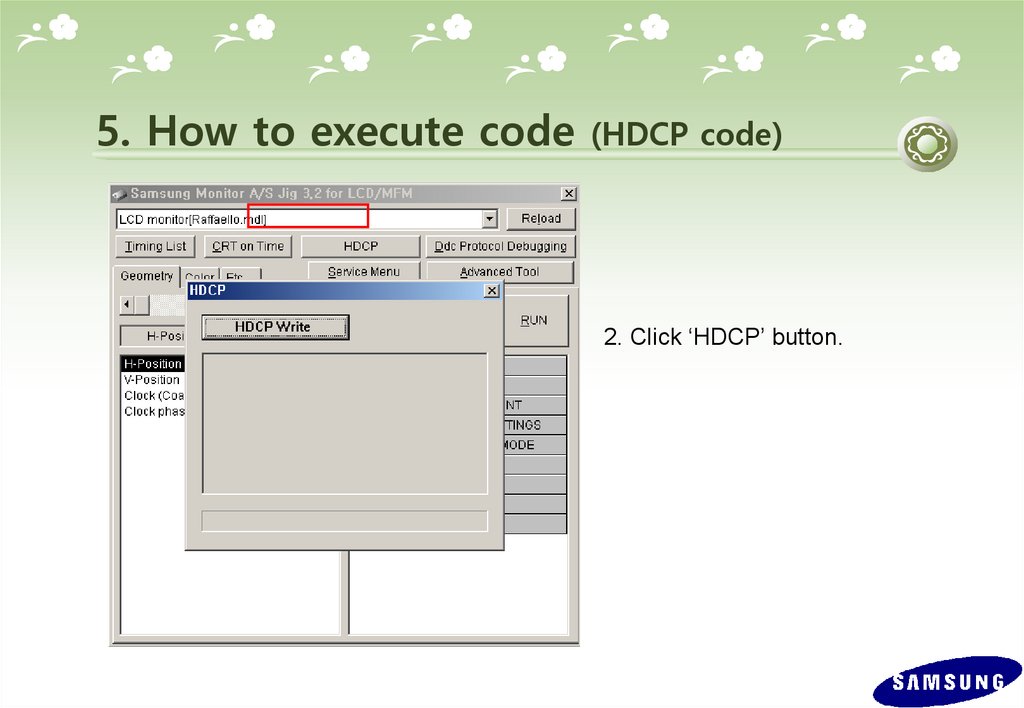
5. How to execute code(HDCP code)
2. Click ‘HDCP’ button.
64.
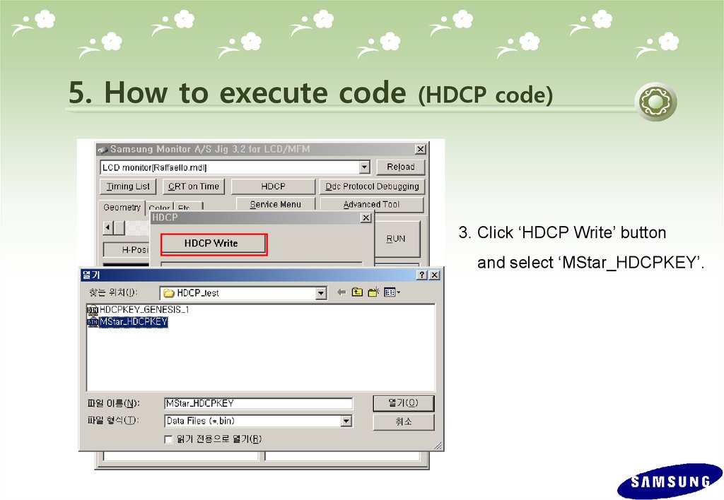
5. How to execute code(HDCP code)
3. Click ‘HDCP Write’ button
and select ‘MStar_HDCPKEY’.
65.
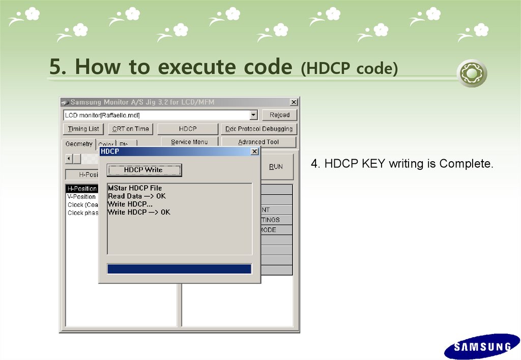
5. How to execute code(HDCP code)
4. HDCP KEY writing is Complete.
66.
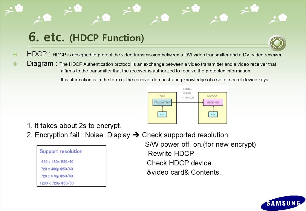
6. etc.(HDCP Function)
HDCP : HDCP is designed to protect the video transmission between a DVI video transmitter and a DVI video receiver
Diagram : The HDCP Authentication protocol is an exchange between a video transmitter and a video receiver that
affirms to the transmitter that the receiver is authorized to receive the protected information.
this affirmation is in the form of the receiver demonstrating knowledge of a set of secret device keys.
1. It takes about 2s to encrypt.
2. Encryption fail : Noise Display Check supported resolution.
S/W power off, on.(for new encrypt)
Support resolution
Rewrite HDCP.
640 x 480p @50/60
Check HDCP device
720 x 480p @50/60
&video card& Contents.
720 x 576p @50/60
1280 x 720p @50/60
67.
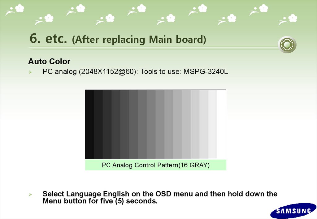
6. etc.(After replacing Main board)
Auto Color
PC analog (2048X1152@60): Tools to use: MSPG-3240L
PC Analog Control Pattern(16 GRAY)
Select Language English on the OSD menu and then hold down the
Menu button for five (5) seconds.