

")

 Improvement made the thermal performance of the existing vapor chamber (VC) (50% MORE")
 with specified")
 with specified technical")

 Промышленность
Похожие презентации:


Two - phase passive thermal devices as a cooling system of power electronic, datacentres, electrical transport, solar receivers
1.
Luikov Heat and Mass Transfer InstituteNational Academy of Sciences of Belarus
Two-phase passive thermal devices as a
cooling system of power electronic, datacentres, electrical transport, solar receivers.
Leonard VASILIEV
BELHUAWEI TECHNOLOGIES LLC
Conference 12 September 2022
2.
AbstractTwo phase thermal passive systems do not have moving parts and are compact,
reliable, and cost-effective. Fluid motion in these passive devices could be driven by
capillary force, gravity, osmotic pressure, and/or concentration gradient. The
fundamental mechanisms and limitations of transport phenomena for passive systems
are highlighted, followed by their applications in heat pipes, thermosyphons, vapor
chambers, electronic devices, solar cooling, thermal energy storage, and electric
transport. The capabilities of the passive systems are limited based on the balance
between the driving force and transport resistance. Based on the fundamental
understanding of fluid flow and phase change in passive systems, this study proposes
associated transport phenomena and quantitative criteria to determine the maximum
heat transfer rate, the transport distance, and minimum pore size of wick structures
(when relevant) in these passive devices.
3.
Boiling and condensation are the key heat-transfer modes with high heattransfer coefficients and widespread applications in various industries and
processes. The classical case for boiling is nucleate pool boiling, which started
to be investigated at the beginning of the 20th century. Despite a long-term
history of research into boiling heat transfer, we still have two groups of
scientists who believe that the thermophysical properties of the boiling surface
and its microstructure impact the heat transfer coefficient, and another group
denies this impact. Therefore, more details and thorough experiments should
be performed to extend our knowledge of various parameters impacting basic
boiling characteristics.
Flow boiling is an even more intense heat-transfer process and is widely used
in various heat-transfer devices and equipment, including thermal and nuclear
power plants. This type of boiling is more complicated than nuclear pool boiling
and contains more characteristics/parameters, which have to be calculated.
Condensation is another high-intensity heat-transfer process which is widely
used in the Rankine power cycle and other industrial processes. Therefore, it
is important to follow up with the latest advances in boiling and condensation.
4.
Part 1Contracts:
Short Historical overeviews of the
Porous media laboratory
Luikov HMTI NAN, Belarus with
HUAWEI, CHINA 2014 – 2022
(some examples)
5.
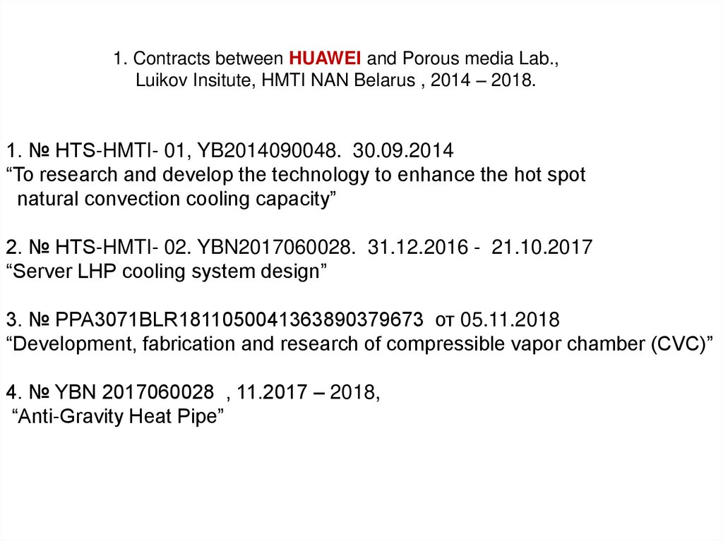
1. Contracts between HUAWEI and Porous media Lab.,Luikov Insitute, HMTI NAN Belarus , 2014 – 2018.
1. № HTS-HMTI- 01, YB2014090048. 30.09.2014
“To research and develop the technology to enhance the hot spot
natural convection cooling capacity”
2. № HTS-HMTI- 02. YBN2017060028. 31.12.2016 - 21.10.2017
“Server LHP cooling system design”
3. № PPA3071BLR1811050041363890379673 от 05.11.2018
“Development, fabrication and research of compressible vapor chamber (CVC)”
4. № YBN 2017060028 , 11.2017 – 2018,
“Anti-Gravity Heat Pipe”
6.
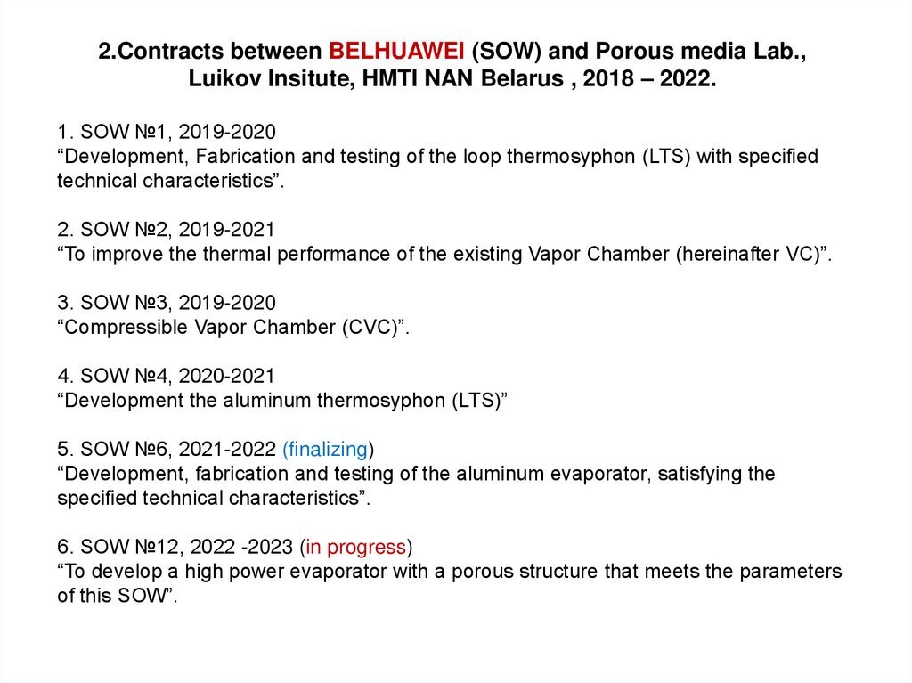
2.Contracts between BELHUAWEI (SOW) and Porous media Lab.,Luikov Insitute, HMTI NAN Belarus , 2018 – 2022.
1. SOW №1, 2019-2020
“Development, Fabrication and testing of the loop thermosyphon (LTS) with specified
technical characteristics”.
2. SOW №2, 2019-2021
“To improve the thermal performance of the existing Vapor Chamber (hereinafter VC)”.
3. SOW №3, 2019-2020
“Compressible Vapor Chamber (CVC)”.
4. SOW №4, 2020-2021
“Development the aluminum thermosyphon (LTS)”
5. SOW №6, 2021-2022 (finalizing)
“Development, fabrication and testing of the aluminum evaporator, satisfying the
specified technical characteristics”.
6. SOW №12, 2022 -2023 (in progress)
“To develop a high power evaporator with a porous structure that meets the parameters
of this SOW”.
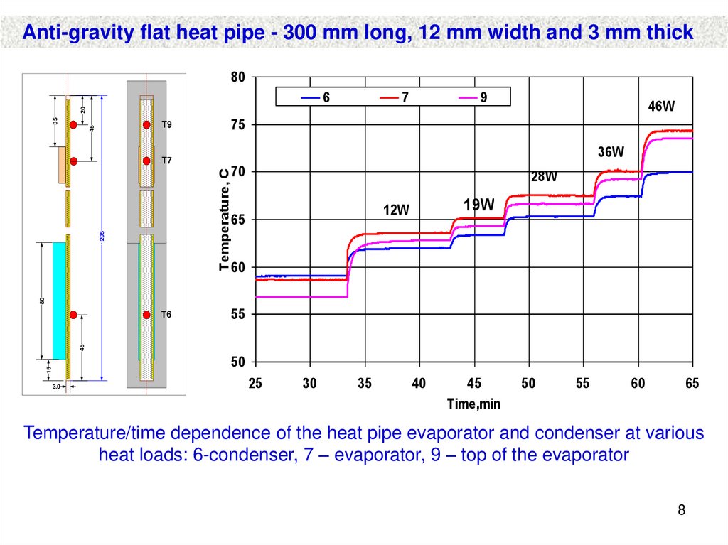
7. 1. № YBN 2017060028 , 11.2017 – 2018, “Anti-Gravity Heat Pipe”
Developed and tested antigravity copper flat heatpipe (heat source above the heat sink) has the open
type
heterogeneous
porous
structure
(sintered
powder) which includes particles of different size
and form, pore sizes decrease along a direction from
the condenser to the evaporator.
The designed antigravity flat heat pipe has a low
mass and low cost production. The
experimental
results represent a certain advances over state-ofthe-art cooling devices in terms of performance,
robustness and simplicity. At a heat load of 35 W, the
surface temperature of the heat pipe is near 70 C for
water as the working fluid.
8.
Anti-gravity flat heat pipe - 300 mm long, 12 mm width and 3 mm thick80
7
9
46W
35
20
6
45
T9
36W
70
28W
Temperature, C
T7
75
~295
19W
12W
65
80
60
55
45
T6
15
50
3.0
25
30
35
40
45
Time,min
50
55
60
65
Temperature/time dependence of the heat pipe evaporator and condenser at various
heat loads: 6-condenser, 7 – evaporator, 9 – top of the evaporator
8
9.
2. Vapor chambers with water as aworking fluid
1. “Development, fabrication and research of compressible
vapor chamber (CVC)”, 2018.
2. “To improve the thermal performance of the existing Vapor
Chamber (hereinafter VC)” 2019-2021.
10.
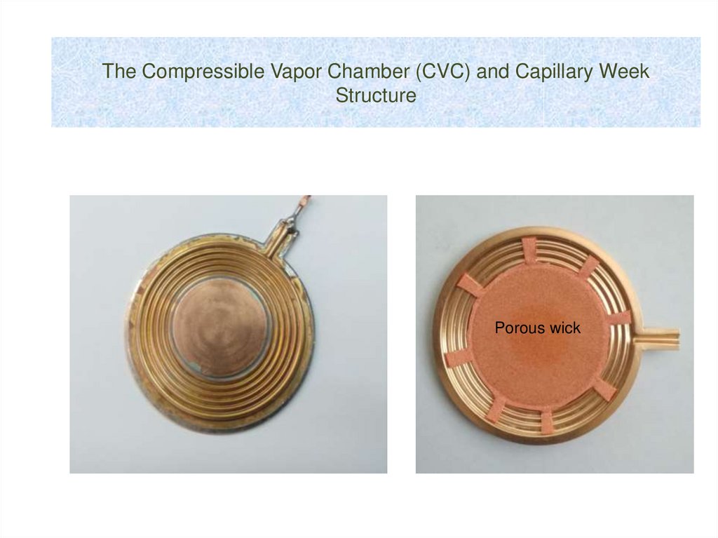
The Compressible Vapor Chamber (CVC) and Capillary WeekStructure
Porous wick
11. 1.Compressible vapor chamber (CVC)
1st stage1.Compressible vapor chamber (CVC)
CVC sample main performances
delivery
Total thickness 5.8mm
Working fluid pure degassed
water
Evaporator outer diameter
23mm
Thermal resistance 0.12K/W
(45W)
CVC
sample
2nd stage
delivery
CVC sample of the 1st stage tested
data
Liquid cooling temperature 60oC
CVC evaporator
design
Cold plate overview
CVC design#1
Rth=0.072K/W –
0.084K/W @60oC, 45W
March 27th, 2019 – April
2nd, 2019
CVC sample of the 2nd stage tested
data
Experimental setup
overview
Heater with holder
overview
Rth < 0.1K/W target was successfully achieved. The main
improvement is evaporator wick design: HTC was increased
from 25,000W/m2K to 75,000W/m2K
12. Conclusions
1. In the process of performing the work, three CVC constructions have been developed,
manufactured and tested to transport the required heat fluxes in a vertical orientation. CVC 1 has
a porous coating on the surface of the evaporator and a mesh coating on the surface of the
membrane for transporting liquid. CVC 2 also has a porous coating on the surface of the
evaporator, and a porous path for transporting liquid from the bottom of the CVC to the surface of
the evaporator. CVC 3 is equipped with an additional metal ring in the area of the condenser to
increase the gap between the capacitor and the membrane. The working liquid in the CVCs is
distilled water. 2. In the process of experiments, the optimal sizes of the CVC evaporator were
determined. The diameter of the evaporator is 34 mm, the thickness of the porous coating is 0.7
mm. Copper powder with particles of a dendritic form and dimensions of 63–100 µm was used for
the porous coating of the evaporator. 3. All three selected types of CVC ensure that the
parameters required in the technical specification are met: the transmitted heat flux is not less
than 45 W, thermal resistance is 0.1 K/W, and the thickness of the device is not more than 5 mm.
Transported heat flux exceeds the required. 4. CVCs have extended connections of individual
elements. In this regard, there is a high probability of the existence of micro-leaks that cannot be
parameters. 5. In some cases, in the manufacture of CVCs using high-temperature processes
(welding, brazing), its elements may be deformed.determined by traditional methods. Since the
internal volume of the CVC is very small, and low pressure must be maintained in it, even a small
amount of air leakage can significantly degrade its
13. 2. Statement of Work No. 2 (SOW-2) Improvement made the thermal performance of the existing vapor chamber (VC) (50% MORE
EFFICIENT)Project Target --- (Twenty two VC’s were delivered)
Temperature difference of the evaporator is reduced by 50% + (from 14.3 to 8 K) with heat flux
104 W/cm2.
Increased heat flux of the vapor chamber by 50%+ (from 104 to 135 W/cm 2) with same
temperature difference(14.3 K).
Vapor chamber with heterogeneous copper porous wick
14.
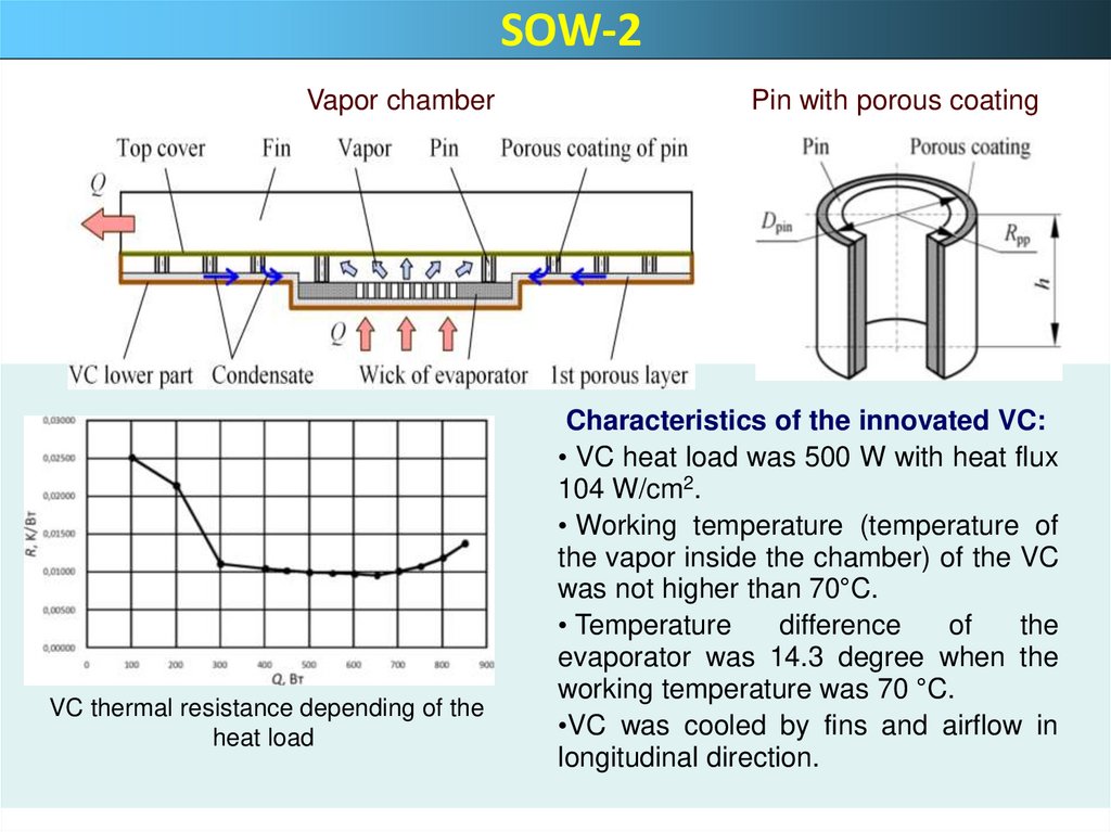
SOW-2Vapor chamber
VC thermal resistance depending of the
heat load
Pin with porous coating
Characteristics of the innovated VC:
• VC heat load was 500 W with heat flux
104 W/cm2.
• Working temperature (temperature of
the vapor inside the chamber) of the VC
was not higher than 70°C.
• Temperature
difference
of
the
evaporator was 14.3 degree when the
working temperature was 70 °C.
•VC was cooled by fins and airflow in
longitudinal direction.
15. 1. BELHUAWEI SOW №1, 2019-2020 “Development, Fabrication and testing of the alumina loop thermosyphon (LTS) with specified
technical characteristicsThe
design
of
an
aluminum
annular
thermosiphon (LTS) for cooling high-power
electronic devices has been developed, made
and studied.
R245fa is used as a working fluid.
Heat flow of 420 W with a total thermal
resistance R of no more than 0.12 K/W from
the heat source to the ambient air is transferred
.
16. SOW №1, 2019-2020 “Development, Fabrication and testing of the alumina loop thermosyphon (LTS) with specified technical
characteristicsThermal resistance of LTS is near R = 0.02 K/W with a heat transfer coefficient h =
110,000 W/m2K. The thermal resistance of such a heat exchanger between the heat
sink and the cooling air is 0.076 - 0.08 K/W. A high vapor pressure (up to 7 bar) is
available in the LTS cavity when R245fa is used as a working fluid.
The maximum heat flow transferred by the LTS
(acetone as a working fluid)
exceeded 500 W with a heat flux density of more than 100 W / m2.
The thermal resistance of the tested samples of the LTS evaporators was within 0.1 -
0.05 K / W. The best heat transfer rates were obtained for samples of evaporators
with mini grooves and a minicoating of porous AL2O3 with a thickness of 50-200
microns. The heat exchangers --- condensers available for manufacture had a
thermal resistance of 0.06 - 0.1 K / W.
17. Members of Porous media Lab.HMTI.AS.NANB
Executive team1. Leonard Vasiliev, prof, Dr.
Sci, team leader
2. Alexander Zhuravlyov , PhD
researcher
3. Leonid Grakovich,
PhD
researcher
4. Michail Rabetsky,
PhD
researcher
5. Valery Aliakhnovich,
researcher
6. Larisa Dragun,
researcher
7. Dmitry Sadchenko,
researcher
8. Maxim Kuzmich
researcher
9.Alexander Khartonik
researcher