


 Строительство
Похожие презентации:


")

")


Compressed elements of constant cross section. Compressed transition elements of constant cross section
1.
Compressed elements of constant• Образец текста
cross section. Compressed
• Второй уровень
elements of constant
• Третийtransition
уровень
• Четвертый уровень cross section
• Пятый уровень
2.
Құрылыс құралымдарыPillars are one of the oldest building structures.
More than 3,000 years ago, the Egyptians
carved stone pillars for tombstones. In the fifth
century, pillars were often used in public
buildings by the ancient Persians, Greeks, and
Romans.
At that time, the pillars were built only
according to empirical rules, looking at the
surrounding buildings.
3.
Parthenon TempleBy order of Pericles, B.C. 447 and BC Graduated in 432.
There are 8 columns on the contact facades of the
rectangular building, and 17 along the length.
4.
Persepolis is an ancient Iranian complexBC 518 Xerxes I graduated from Darius
Corridor of a hundred pillars
5.
• The scientific study of the problems ofthe work of compressible elements
began in the XVIII century when Peter
Van-Musschenbrook developed a test
tool for compression and Leonard Euler
developed his famous formula.
6.
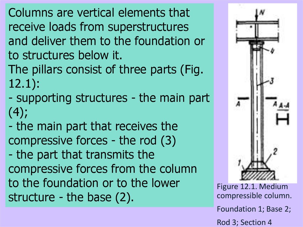
Columns are vertical elements thatreceive loads from superstructures
and deliver them to the foundation or
to structures below it.
The pillars consist of three parts (Fig.
12.1):
- supporting structures - the main part
(4);
- the main part that receives the
compressive forces - the rod (3)
- the part that transmits the
compressive forces from the column
to the foundation or to the lower
Figure 12.1. Medium
compressible column.
structure - the base (2).
Foundation 1; Base 2;
Rod 3; Section 4
7.
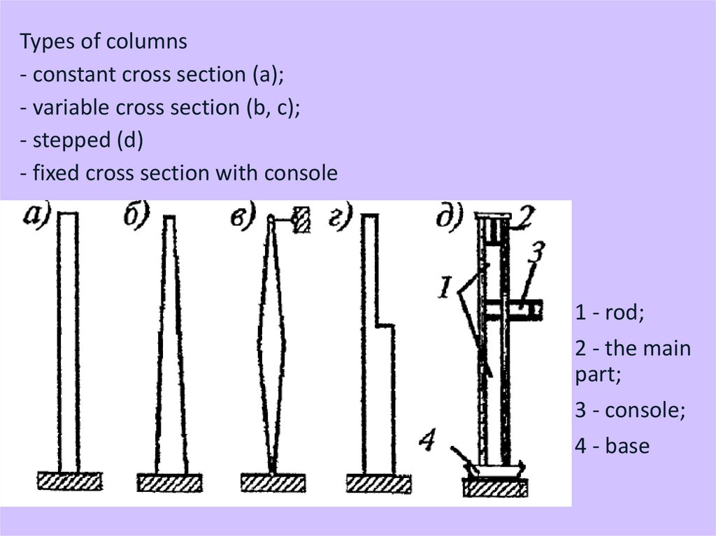
Types of columns- constant cross section (a);
- variable cross section (b, c);
- stepped (d)
- fixed cross section with console
1 - rod;
2 - the main
part;
3 - console;
4 - base
8.
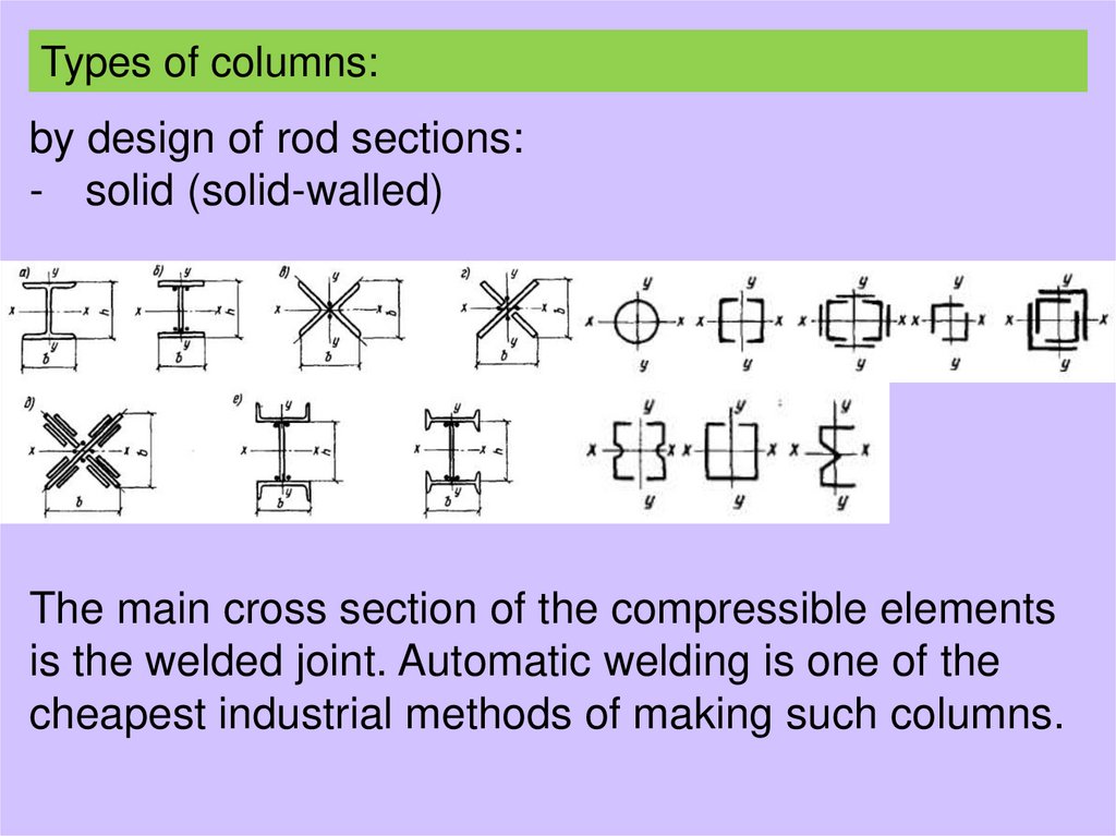
Types of columns:by design of rod sections:
- solid (solid-walled)
The main cross section of the compressible elements
is the welded joint. Automatic welding is one of the
cheapest industrial methods of making such columns.
9.
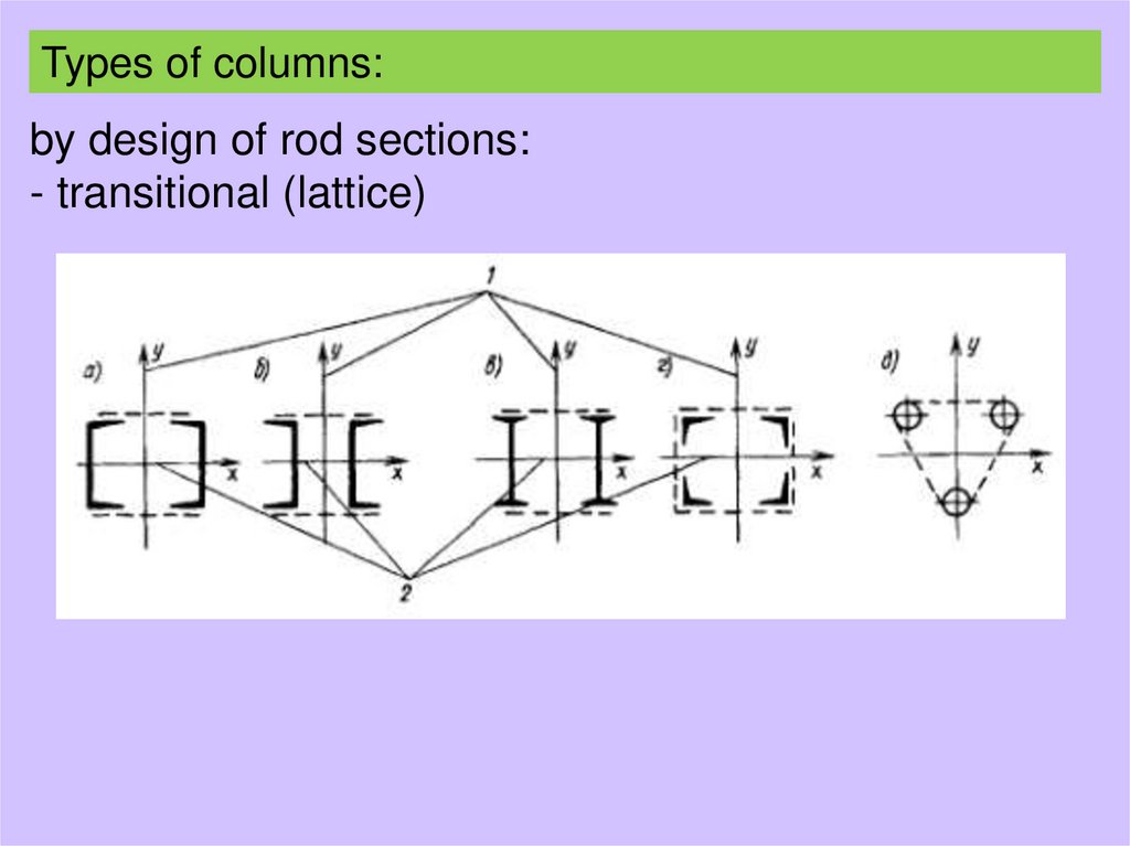
Types of columns:by design of rod sections:
- transitional (lattice)
10.
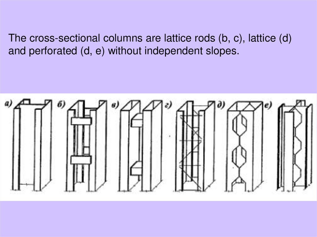
The cross-sectional columns are lattice rods (b, c), lattice (d)and perforated (d, e) without independent slopes.
11.
The maximum design load of a transitionbeam with a cross section of two
channels is 2700 ÷ 3500 kN, from two
girders - 5500 ÷ 5600 kN.
As the load increases, it becomes more
difficult to prepare the cross-section of
the transition beams, so they should be
made as a whole.
12.
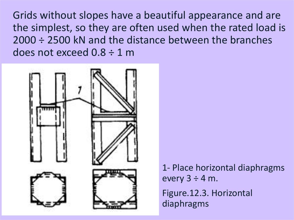
Grids without slopes have a beautiful appearance and arethe simplest, so they are often used when the rated load is
2000 ÷ 2500 kN and the distance between the branches
does not exceed 0.8 ÷ 1 m
1- Place horizontal diaphragms
every 3 ÷ 4 m.
Figure.12.3. Horizontal
diaphragms
13.
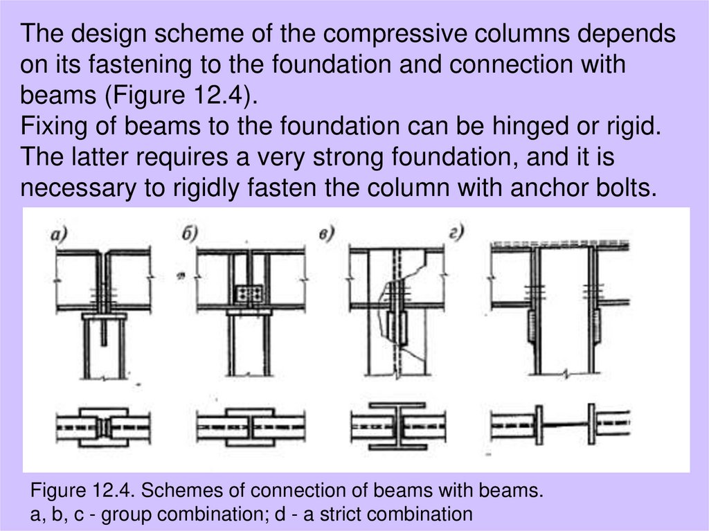
The design scheme of the compressive columns dependson its fastening to the foundation and connection with
beams (Figure 12.4).
Fixing of beams to the foundation can be hinged or rigid.
The latter requires a very strong foundation, and it is
necessary to rigidly fasten the column with anchor bolts.
Figure 12.4. Schemes of connection of beams with beams.
a, b, c - group combination; d - a strict combination
14.
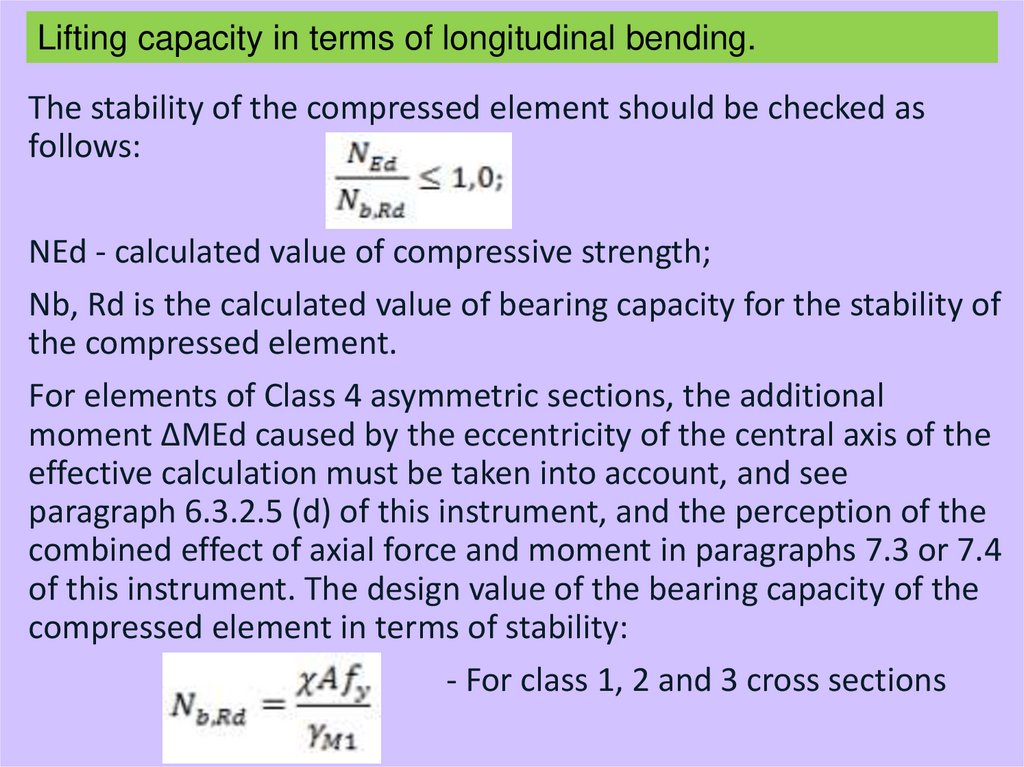
Lifting capacity in terms of longitudinal bending.The stability of the compressed element should be checked as
follows:
NEd - calculated value of compressive strength;
Nb, Rd is the calculated value of bearing capacity for the stability of
the compressed element.
For elements of Class 4 asymmetric sections, the additional
moment ΔMEd caused by the eccentricity of the central axis of the
effective calculation must be taken into account, and see
paragraph 6.3.2.5 (d) of this instrument, and the perception of the
combined effect of axial force and moment in paragraphs 7.3 or 7.4
of this instrument. The design value of the bearing capacity of the
compressed element in terms of stability:
- For class 1, 2 and 3 cross sections
15.
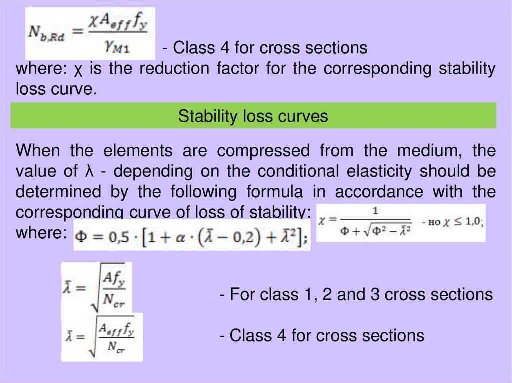
- Class 4 for cross sectionswhere: χ is the reduction factor for the corresponding stability
loss curve.
Stability loss curves
When the elements are compressed from the medium, the
value of λ - depending on the conditional elasticity should be
determined by the following formula in accordance with the
corresponding curve of loss of stability:
where:
- For class 1, 2 and 3 cross sections
- Class 4 for cross sections
16.
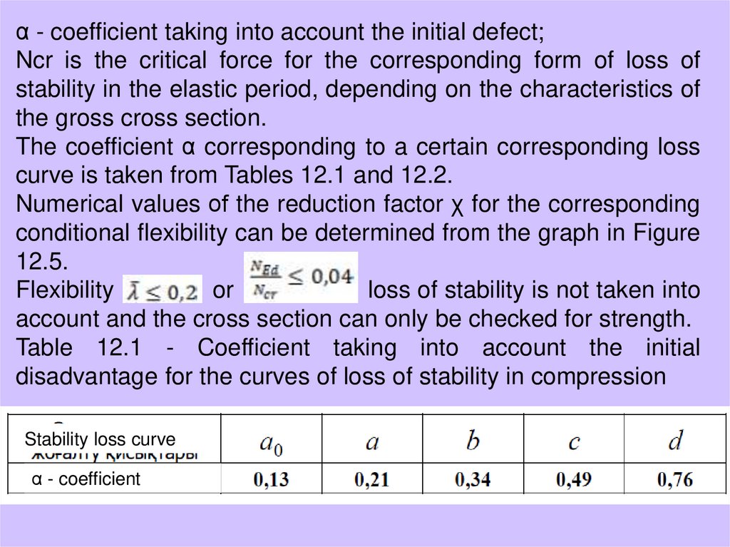
α - coefficient taking into account the initial defect;Ncr is the critical force for the corresponding form of loss of
stability in the elastic period, depending on the characteristics of
the gross cross section.
The coefficient α corresponding to a certain corresponding loss
curve is taken from Tables 12.1 and 12.2.
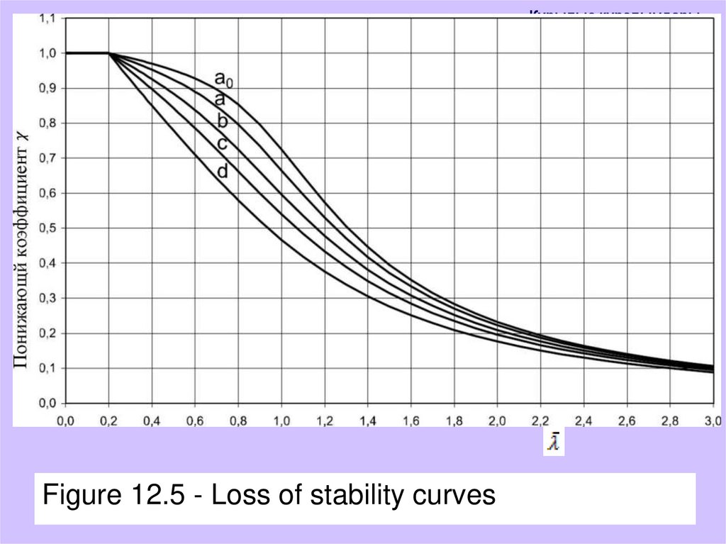
Numerical values of the reduction factor χ for the corresponding
conditional flexibility can be determined from the graph in Figure
12.5.
Flexibility
or
loss of stability is not taken into
account and the cross section can only be checked for strength.
Table 12.1 - Coefficient taking into account the initial
disadvantage for the curves of loss of stability in compression
Stability loss curve
α - coefficient
17.
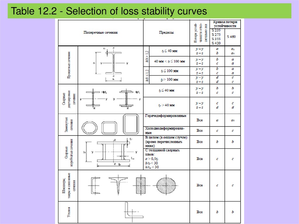
Table 12.2 - Selection of loss stability curves18.
Құрылыс құралымдарыFigure 12.5 - Loss of stability curves
19.
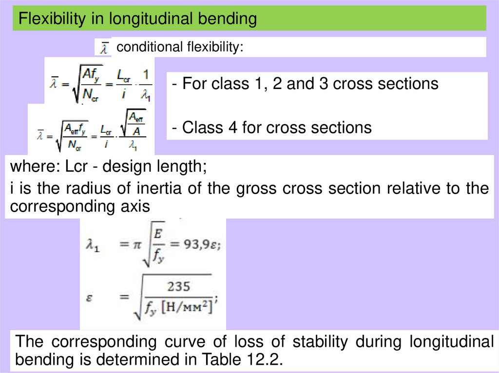
Flexibility in longitudinal bendingҚұрылыс құралымдары
conditional flexibility:
- For class 1, 2 and 3 cross sections
- Class 4 for cross sections
where: Lcr - design length;
i is the radius of inertia of the gross cross section relative to the
corresponding axis
The corresponding curve of loss of stability during longitudinal
bending is determined in Table 12.2.
20.
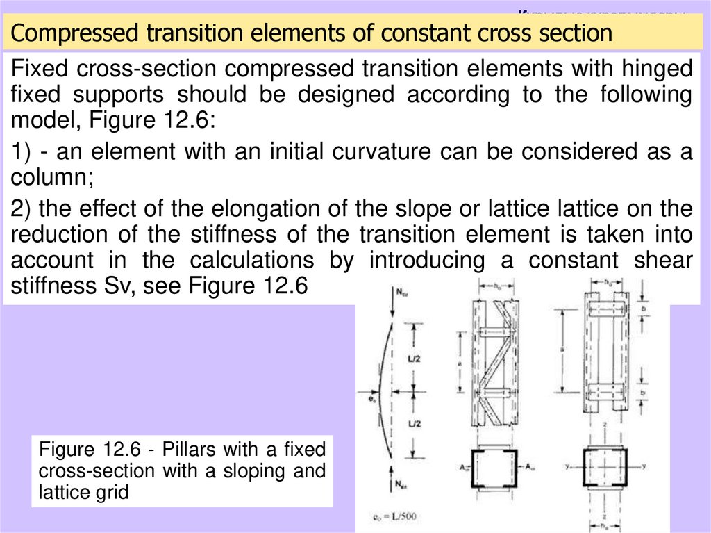
Құрылыс құралымдарыCompressed transition elements of constant cross section
Fixed cross-section compressed transition elements with hinged
fixed supports should be designed according to the following
model, Figure 12.6:
1) - an element with an initial curvature can be considered as a
column;
2) the effect of the elongation of the slope or lattice lattice on the
reduction of the stiffness of the transition element is taken into
account in the calculations by introducing a constant shear
stiffness Sv, see Figure 12.6
Figure 12.6 - Pillars with a fixed
cross-section with a sloping and
lattice grid
21.
Құрылысқұралымдары
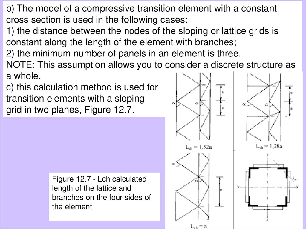
b) The model of a compressive transition element with
a constant
cross section is used in the following cases:
1) the distance between the nodes of the sloping or lattice grids is
constant along the length of the element with branches;
2) the minimum number of panels in an element is three.
NOTE: This assumption allows you to consider a discrete structure as
a whole.
c) this calculation method is used for
transition elements with a sloping
grid in two planes, Figure 12.7.
Figure 12.7 - Lch calculated
length of the lattice and
branches on the four sides of
the element
22.
Құрылыс құралымдарыd) The branches may have a single cross-section or a transition with sloping or lattice
grids relative to the y-y axis.
e) When checking the branches, use the compressive forces in the branches Nch, Ed,
resulting from the compression forces NEd and the moments MEd in the middle of the
transition element interval.
e) For an element with two identical shelves, the calculation force Nch, Ed should be
determined by the following formula:
where
NEd - the calculated value of the compressive force acting on the transition element;
H0 the distance between the centers of gravity of points;
Ach-cross section of one branch;
Ieff is the moment of inertia of the effective section passing through the element, see
paragraphs 8.2 and 8.3 of this tool;
MEd- the maximum design moment in the middle of the length of the transition
element from the effects of the second type:
23.
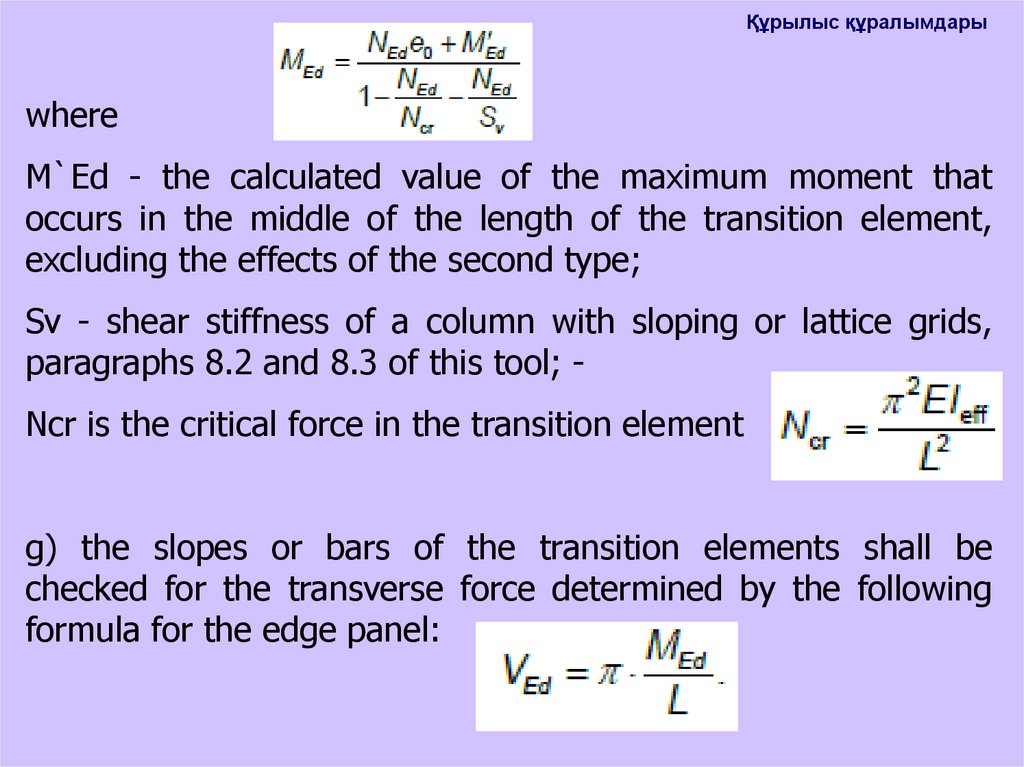
Құрылыс құралымдарыwhere
M`Ed - the calculated value of the maximum moment that
occurs in the middle of the length of the transition element,
excluding the effects of the second type;
Sv - shear stiffness of a column with sloping or lattice grids,
paragraphs 8.2 and 8.3 of this tool; Ncr is the critical force in the transition element
g) the slopes or bars of the transition elements shall be
checked for the transverse force determined by the following
formula for the edge panel:
24.
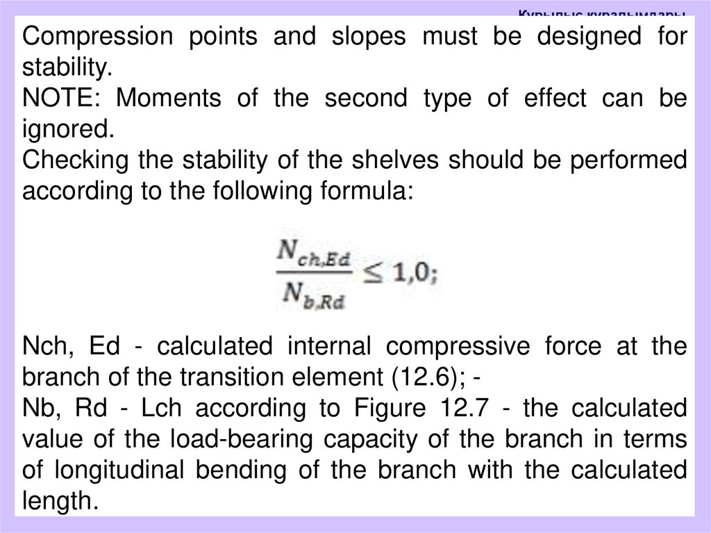
Құрылыс құралымдарыCompression points and slopes must be designed for
stability.
NOTE: Moments of the second type of effect can be
ignored.
Checking the stability of the shelves should be performed
according to the following formula:
Nch, Ed - calculated internal compressive force at the
branch of the transition element (12.6); Nb, Rd - Lch according to Figure 12.7 - the calculated
value of the load-bearing capacity of the branch in terms
of longitudinal bending of the branch with the calculated
length.