


 Физика
Похожие презентации:


Calculation of statically uncertainable rod systems by the method of forces
1.
CALCULATION OF STATICALLYUNCERTAINABLE ROD SYSTEMS BY THE
METHOD OF FORCES
2. 1. Determination of the number of extra connections of a flat system
The number of degrees of freedom of a system is the number of independentcoordinates that determine the position of all its elements. When determining the
number of degrees of freedom, elements of the system are considered absolutely
solid.
Figure system and has six
degrees of freedom, since to
determine the positions of its two
elements relative to the xy
reference system, it is necessary
to set six independent
coordinates, for which xA, yA, α1,
xB2, yB2 and α2 can be taken.
Connections are bodies that reduce the number of degrees of freedom of a
system.
In fig. Used elements of the system connected pivotally. The number of independent
coordinates defining their positions decreased to four xA, yA, xB, and α2. Consequently,
a flat hinge in which two elements converge (double) reduces the number of sloboda
degrees by two (imposes two links on the system).
3.
Similarly, it can be shown that the Katkov connection reduces the number of degrees offreedom of the system by one. On the contrary, the removal of a double hinge or roller is
equivalent to the removal, respectively, of two bonds and one bond.
A bond (a body reducing the number of degrees of freedom by one) can be
conventionally depicted as a rod pivotally connected to parts of the system. In theoretical
mechanics, the relations corresponding to the roller, hinge, sliding and blind fittings were
studied.
Since the body has three degrees of freedom in the plane, for its immobility relative to
the reference system there must be at least three bonds between them, the directions of
which do not intersect at one point.
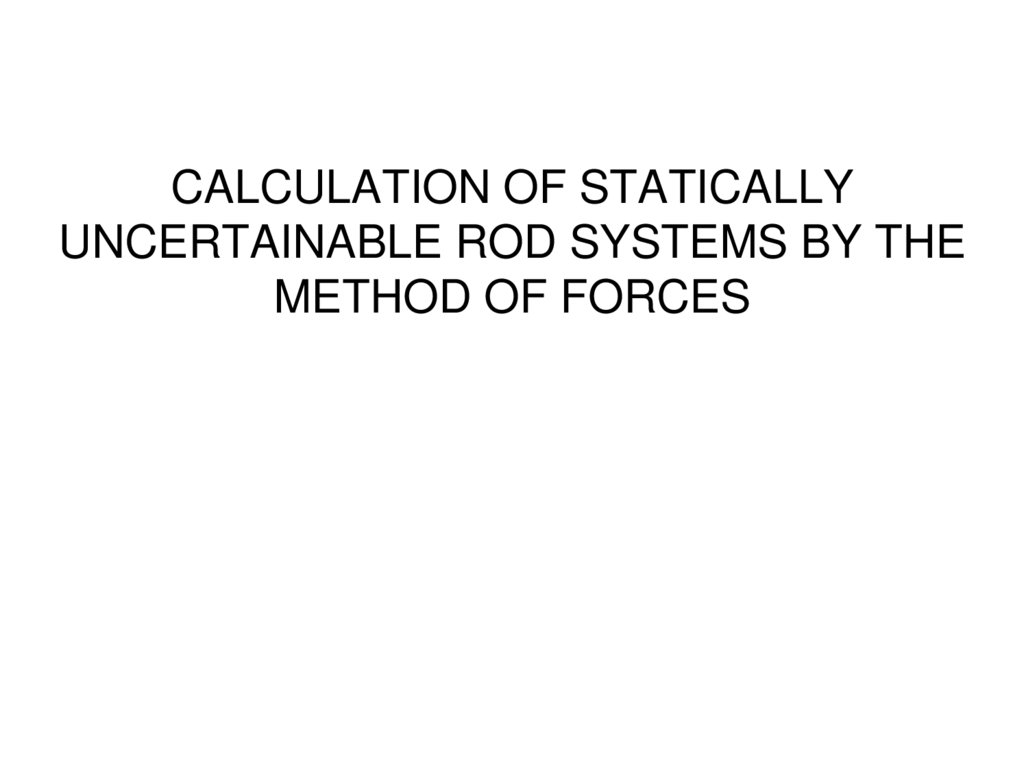
If you mentally cut a timber (fig. A) with section a - a into two parts, then to preserve the
mutual immobility of the parts, you can imagine them to be connected by three
connections (blind seal) (fig. B). Hence, a section of the system in any section is
equivalent to the removal of three bonds.
The system is geometrically immutable, if the mutual displacements of its points
can occur only due to deformation.
Relations, the removal of which does not
violate the geometric immutability of the
system, are called superfluous.
4.
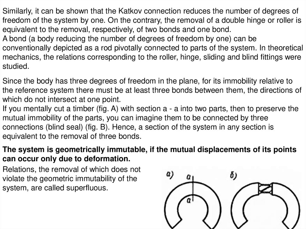
A contour is a closed line formed by the axes of the elements of the system, thebounding area, within which there are no axial lines connecting the points of the
contour.
The hingeless contour (Fig. A) contains three extra
connections, since its cut across any section (Fig. B)
does not break the geometric immutability (there are
three connections in any section of the cut contour).
A single-hinge contour contains two extra
connections, since the removal of a hinge does not
violate its geometrical immutability. Comparing these
contours, we conclude that a double hinge reduces
the number of extra connections by one.
Therefore, two-hinged and three-hinged contours will
contain, respectively, one extra link and not a single
extra link. It can be proved that the hinge in which the
i elements converge reduces the number of
unnecessary connections of the system by i — 1.
5.
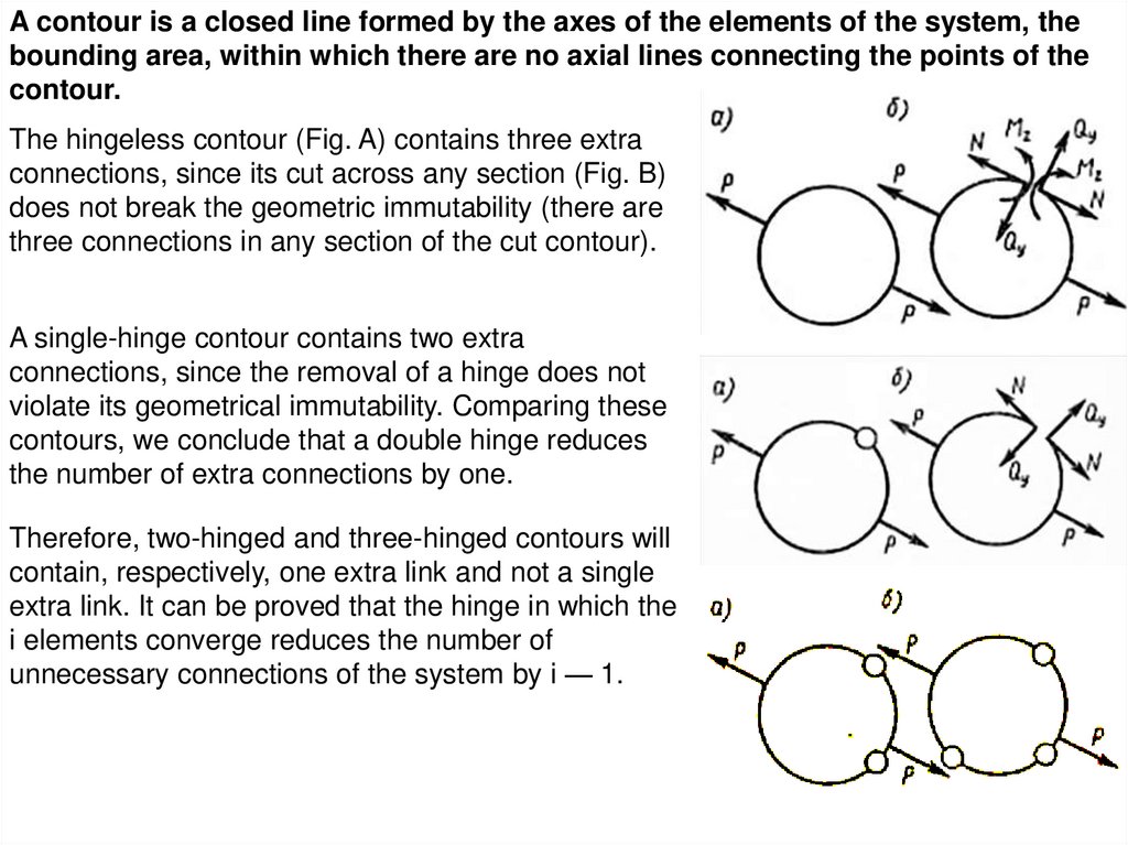
The contour with a katkovy connection contains oneextra connection, since the removal of the roller (Fig.
B) does not violate its geometrical immutability.
Consequently, the roller reduces the number of
unnecessary contour connections by two.
It is possible to formulate unconditional signs of the geometric immutability of the
system.
The system is geometrically unchanged if:
1. each contour that is included in its composition contains no more than three
hinges;
2. any two of its geometrically unchanged parts are connected by at least three
bonds, the directions of which do not intersect at one point (in particular, are
not parallel);
3. by successive removal of its geometrically immutable parts, you have with
three links that attach them to the system, a geometrically immutable system.
Connections between parts of the system are called internal. If a system element is not
a calculated object, then the relations between it and the rest of the system are called
external. An element that is not a calculated object is called a reference. A system that
does not have external connections is called free, and one that has them is attached.
6.
Let the system: t - the number of extra connections; n is the number of contours; p2 isthe number of double hinges; p3 is the number of triple hinges; ...; pi is the number of
hinges in which i elements converge; pk is the number of Katkov bonds.
Each contour can contain no more than three extra links, so their maximum possible
number in the system is 3n; each hinge reduces the number of unnecessary
connections of the system by one less than the number of elements converging in it;
Each roller reduces the number of unnecessary system connections by two. therefore
m 3n p2 2 p3 ... (i 1) pi 2 pk
The formula can be used to make sure that the system is geometrically unchanged.
Consider examples
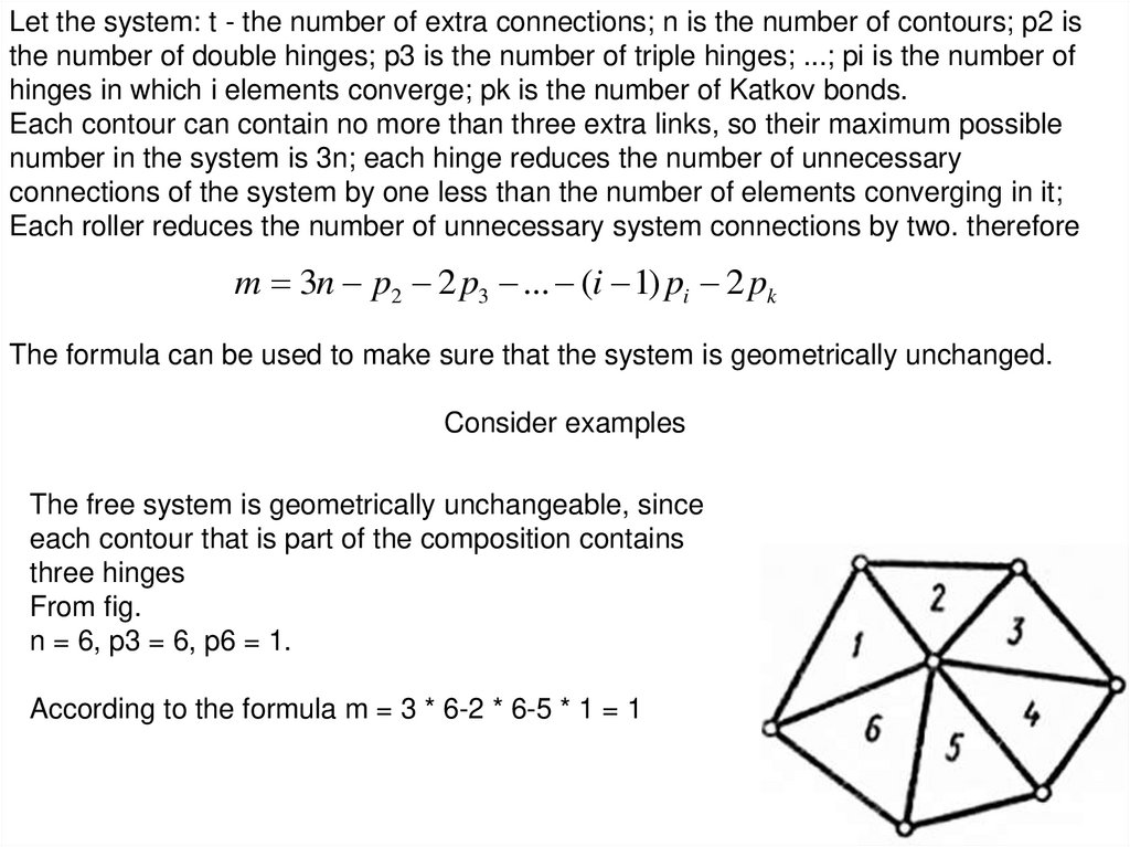
The free system is geometrically unchangeable, since
each contour that is part of the composition contains
three hinges
From fig.
n = 6, p3 = 6, p6 = 1.
According to the formula m = 3 * 6-2 * 6-5 * 1 = 1
7.
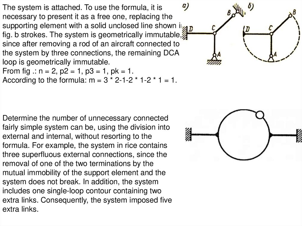
The system is attached. To use the formula, it isnecessary to present it as a free one, replacing the
supporting element with a solid unclosed line shown in
fig. b strokes. The system is geometrically immutable,
since after removing a rod of an aircraft connected to
the system by three connections, the remaining DCA
loop is geometrically immutable.
From fig .: n = 2, p2 = 1, p3 = 1, pk = 1.
According to the formula: m = 3 * 2-1-2 * 1-2 * 1 = 1.
Determine the number of unnecessary connected
fairly simple system can be, using the division into
external and internal, without resorting to the
formula. For example, the system in rice contains
three superfluous external connections, since the
removal of one of the two terminations by the
mutual immobility of the support element and the
system does not break. In addition, the system
includes one single-loop contour containing two
extra links. Consequently, the system imposed five
extra links.
8. 2. The degree of static indefinability of the system
A system is statically indefinable if, in any of its cross sections, the values ofinternal force factors cannot be found using the static equations alone.
The degree of static indefinability is the difference between the number of
equations required to determine the values of internal power factors in any
section of the system, and the number of statics equations that can be used for
this.
In the sequel, the degree of static indefinability will be denoted by k.
According to the axiom of static communications, you can discard them,
replacing their action on the system with forces.
Cutting the contour in an arbitrary section, we discard
three links. In order for the contour to work under the
same conditions as before the cut, the action of the parts
on each other should be replaced by three internal force
factors N, Qy and Mz,
arising in the general case in the cross section of the frame element of a flat system,
directed by virtue of the law of action and reaction, as shown in fig. b To determine these
factors, no static equation can be used: they all turn into identities, that is, they will be
valid for any values of N, Qy and Mz. Therefore, a closed loop is three times statically
undefined.
9.
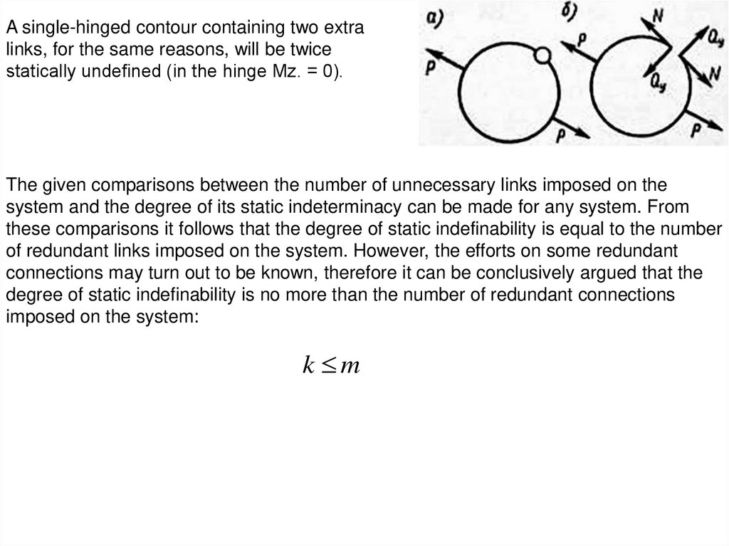
A single-hinged contour containing two extralinks, for the same reasons, will be twice
statically undefined (in the hinge Мz. = 0).
The given comparisons between the number of unnecessary links imposed on the
system and the degree of its static indeterminacy can be made for any system. From
these comparisons it follows that the degree of static indefinability is equal to the number
of redundant links imposed on the system. However, the efforts on some redundant
connections may turn out to be known, therefore it can be conclusively argued that the
degree of static indefinability is no more than the number of redundant connections
imposed on the system:
k m
10.
A system is called instantly changeable if thedirections of the links connecting the geometrically
unchanging parts connecting it intersect at one point
or if these parts are joined by more than two hinges
lying on one straight line.
The degree of static indefinability of an instantly
changeable system will be more pure the extra links
that are imposed on it. For example, the system (fig.
A) does not contain unnecessary links, but it will not
be possible to determine the efforts in the rods from
the static equations, since (fig. B)
m p h 0
o
в)
г)
The same can be said about systems (fig. C, d).
To determine the internal force factors in instantly
changeable systems, even if they are
do not carry extra connections, you have to consider their deformed state. The solution
of the problem is complicated by the fact that in such systems the relationship between
forces and displacements is nonlinear. When designing systems, special attention
should be paid to the fact that they are not instantly changeable, since relatively small
external forces can create very large internal force factors in such systems.
11. 3. Equivalent system and canonical equations of the method of forces
An equivalent system is a system derived from a given one by removingunnecessary connections and replacing their action with a system by generalized
forces, which in the method of forces are denoted by Xi and are called extra
unknowns. The process of determining Xi is sometimes referred to as revealing
the static indeterminacy of a system.
The main system is the equivalent system without any external factors and extra
unknowns.
For brevity, absolute and relative generalized displacement of sections in the equivalent
and the main (when it is loaded) systems will be simply called displacements. Denote by
Δi - the movement of the section along the i-th direction in the given system.
Suppose that on a given system there are m
superfluous links (the dotted line in the figure
denotes unrepresented links). Transforming this
system into an equivalent, we keep between it
and the supporting element, which is usually
taken as the reference system, for their mutual
immobility, three links. Let Э be the equivalent
system.
12.
Let us denote: δip - displacement of the section,in which Xi is applied along its direction, in the
main system when it is loaded with specified
forces (δip is displacement in the i-th direction in
the main system from the specified forces); δiT movement along the i-th direction in the main
system from T (temperature changes);
δij - movement in the i-th direction in the main system from a single generalized force
applied instead of and in the direction Xj
δij is called unit displacement or ductility. Single movements with the same index are
called the main ones.
The essence of the method of forces:
The equivalent system will work as a given one, if the displacement of the section in
which the extra links were located in the direction of these links in the equivalent system
are equal to the corresponding displacements in the given system, i.e.
1 1, 2 2 ... i i ... m m .
Equivalence conditions for a given and equivalent systems can be written as many as
unnecessary unknowns.
13.
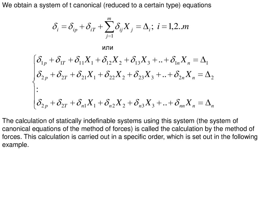
We obtain a system of t canonical (reduced to a certain type) equationsm
i ip iT ij X j i ; i 1,2..m
j 1
или
1 p 1T 11 X 1 12 X 2 13 X 3 .. 1n X n 1
2 p 2T 21 X 1 22 X 2 23 X 3 .. 2 n X n 2
:
2 p 2T n1 X 1 n 2 X 2 n 3 X 3 .. nn X n n
The calculation of statically indefinable systems using this system (the system of
canonical equations of the method of forces) is called the calculation by the method of
forces. This calculation is carried out in a specific order, which is set out in the following
example.
14.
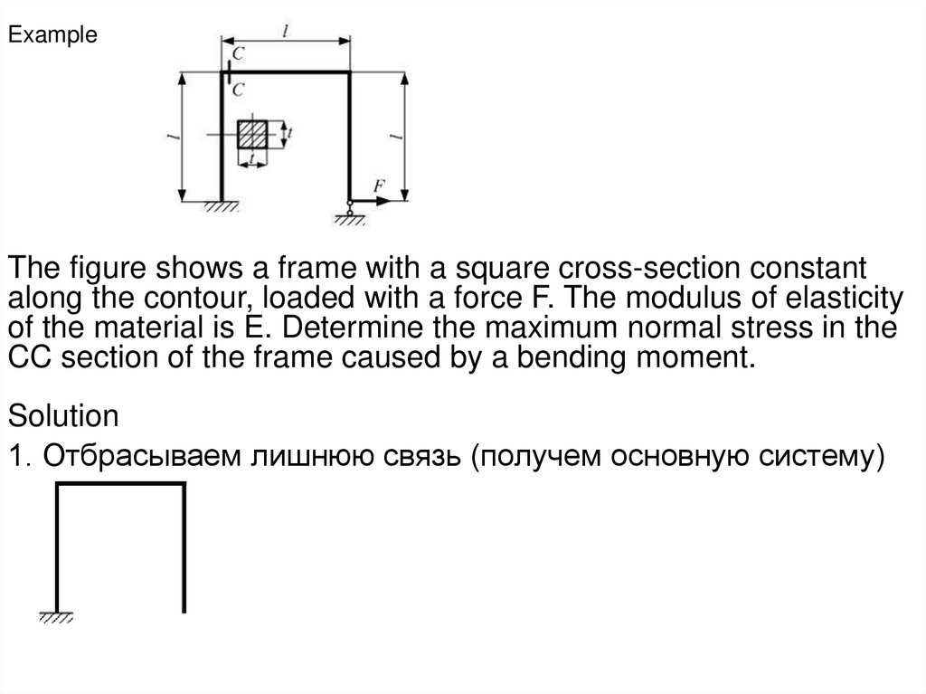
ExampleThe figure shows a frame with a square cross-section constant
along the contour, loaded with a force F. The modulus of elasticity
of the material is E. Determine the maximum normal stress in the
CC section of the frame caused by a bending moment.
Solution
1. Отбрасываем лишнюю связь (получем основную систему)
15.
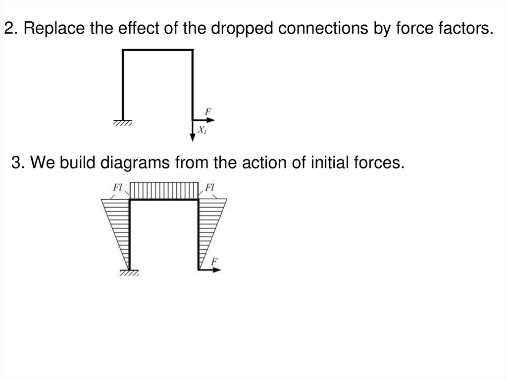
2. Replace the effect of the dropped connections by force factors.3. We build diagrams from the action of initial forces.
16.
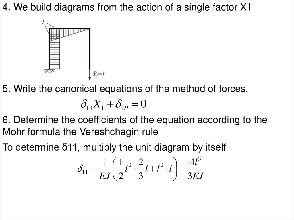
4. We build diagrams from the action of a single factor X15. Write the canonical equations of the method of forces.
11 X1 1P 0
6. Determine the coefficients of the equation according to the
Mohr formula the Vereshchagin rule
To determine δ11, multiply the unit diagram by itself
3
1 1 2 2
4
l
2
11
l l l l
EJ 2
3
3EJ
17.
11 2
Fl 3
2 l
1
Fl Fl l
EJ
2 2
EJ
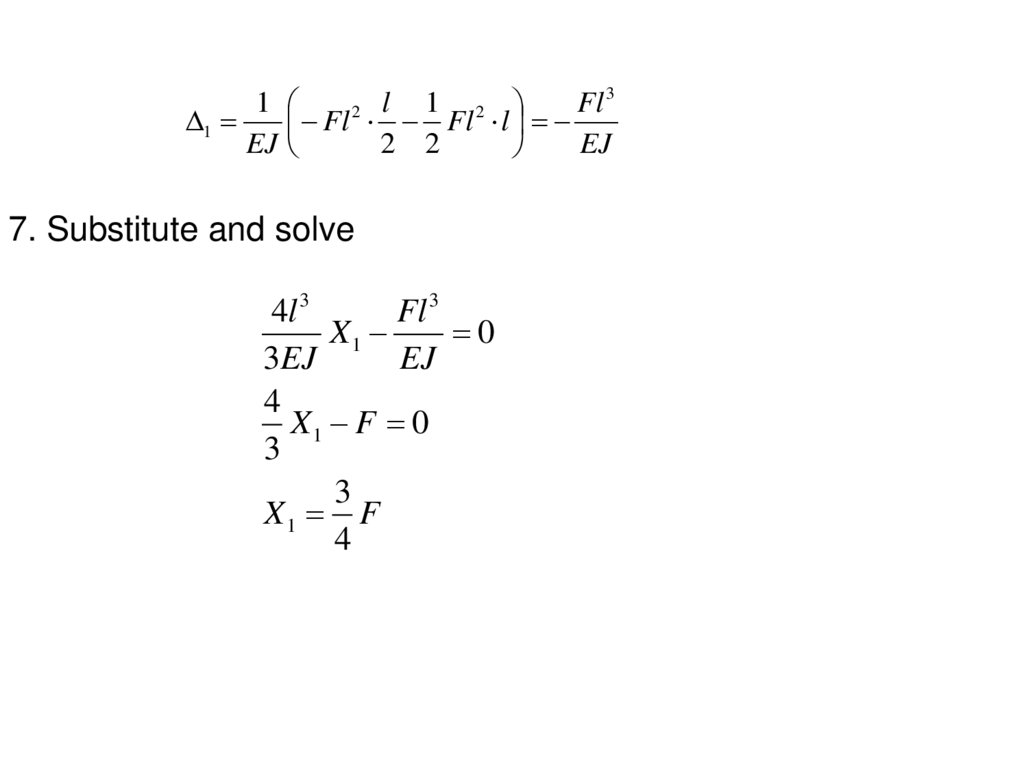
7. Substitute and solve
4l 3
Fl 3
X1
0
3EJ
EJ
4
X1 F 0
3
3
X1 F
4
18.
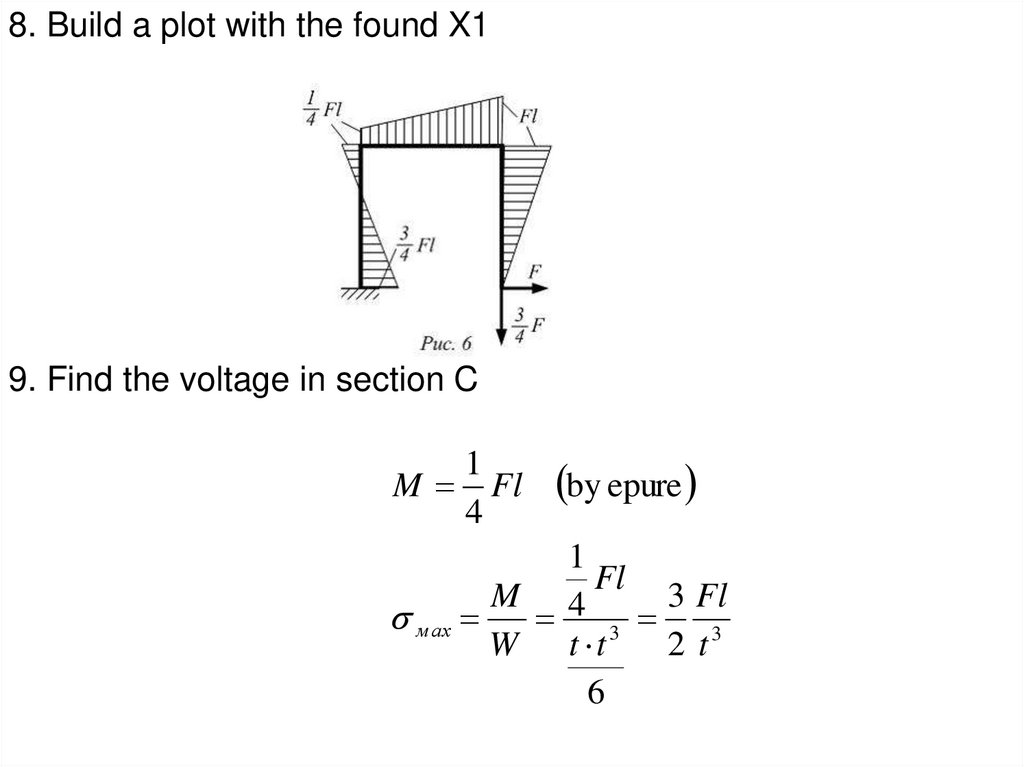
8. Build a plot with the found X19. Find the voltage in section C
1
M Fl
4
by epure
1
Fl
M 4
3 Fl
м ах
3
W t t
2 t3
6
19.
The general order or essence of the method of forces is asfollows:
1. From a given statically indeterminate system, they pass to
the main system - statically determinable and immutable,
which is obtained from the given one by discarding
unnecessary connections.
2. Replace the discarded superfluous connections with their
corresponding reactions, called unknown forces, which are
respectively denoted X1, X2, X3……Xn, where n is the
degree of static indeterminacy.
3. Compose deformation equations expressing the equality
to zero of displacements in the direction of discarded bonds.
4. By solving these equations and determining the unknown
reactions of the discarded bonds, they build diagrams of
internal forces.
20. Choice of the main system of the method of forces
21. The principle of independence of action of forces
1 0,2 0 ......... n 0
( 1 ) x1 ( 1 ) x2 ......( 1 ) xn ( 1 ) p 0
( 2 ) x1 ( 2 ) x2 ......( 2 ) xn ( 2 ) p 0
...............................................................
( n ) x1 ( n ) x2 ......( n ) õ n ( n ) p 0
22. Canonical equations of the force method
x1 11 x 2 12 x3 13 ......... x n 1n 1P 0x1 21 x 2 22 x3 23 ........ x n 2 n 2 P 0
x1 31 x 2 32 x3 33 ........ x n 3n 3 P 0
..................................................................
..................................................................
x1 n1 x 2 n 2 x3 n 3 ........ x n nn nP 0
ik
- represent the movement in the main system in the direction i - the dropped
connection, caused by the unit value of the reaction "k" of the dropped connection,
i.e. Xk=1. Free members
ip
represent displacements in the main system in the direction i - the discarded connection, caused by
external influence p (forces, temperature, displacements of supports, etc. can be used as external
influences).
23. Mohr integrals
The coefficients of canonical equations are determined using Mohrintegrals. To calculate displacements, it is necessary to draw single
diagrams of bending moments in the main system, i.e. diagrams from
the action of the forces Xi =1, Xk=1 ( ), respectively, and separately the
load diagram Mp , which represents the M
diagram
of k
bending moments
i , M
in the main system from external influence р. When bending, the
coefficients and free terms of the canonical equations can be calculated
using the following integral formulas (Mohr formulas):
M i M k dx
ik
,
EI
ip
i,k = 1,2,3……..n
M i M p dx
EI
24. Final diagrams of internal forces
nM Mi Хi M p,
i 1
n
Q Qi X i Q p ,
i 1
n
N Ni X i N p
M,Q,N - final forces: bending moment, transverse and longitudinal forces,
on the right side with a dash
M ,Q, N
- internal forces in the main system from single unknowns, the last terms
M p ,Qp , N p
represent internal forces in the main system from a given external load. The final
internal force plots are checked using deformation and static checks.
i 1
25. Separation of unknowns into symmetric and inversely symmetric
• Canonical Equations for Symmetric Unknownsx1 11 x 3 13 x 5 15 1P 0
x1 31 x 3 33 x 5 35 3 P 0
x1 51 x 3 53 x 5 55 5 P 0
•Canonical equations for inversely symmetric unknowns
x 2 22 x 4 24 x 6 26 2 P 0
x 2 42 x 4 44 x 6 46 4 P 0
x 2 62 x 4 64 x 6 66 6 P 0
26. Grouping unknowns
x1 11 x 3 13 x 5 15 1P 0x 2 22 x 4 24 x 6 26 2 P 0
x1 31 x 3 33 x 5 35 3 P 0
x 2 42 x 4 44 x 6 46 4 P 0
x1 51 x 3 53 x 5 55 5 P 0
x 2 62 x 4 64 x 6 66 6 P 0
27. Features of symmetrical systems
Symmetric systems are systems in whichthere is an axis of symmetry.
In a symmetrical system, symmetrical forces
and symmetrical displacements arise from a
symmetrical load.
In
a
symmetrical
system,
inversely
symmetrical
forces
and
symmetrical
displacements arise from an inversely
symmetrical load.
28.
The degree of static indeterminacy iscalculated by the following formula:
n= 3K-Sh
The main system of the method of forces is
obtained from the given one by discarding
unnecessary connections. To preserve the
symmetry of the system, we choose the main
system as symmetric, i.e. We use the
grouping of unknowns. We divide all unknown
reactions of discarded bonds into symmetrical
and inversely symmetrical.
29.
The use of symmetry makes it possible todivide the system of canonical equations into
two systems: one is symmetric and the other is
inversely symmetric, and the unknowns in
them, respectively, are the symmetric and
inversely symmetric reactions of discarded
bonds. This reduces the amount of
computation.
If the given external load is asymmetric, then it
is necessary to decompose it into symmetrical
and inversely symmetrical.
30. Static and kinematic checks of M, Q, N diagrams
• Static checksF 0, F 0
x
y
• Kinematic checks
M i Mdx
0
EI
M s Mdx
EI 0,
i 1,2,...n
M s M 1 M 2 ... M n
31. Construction of diagrams of transverse and longitudinal forces
QdM
dx
Q Q áàë
Ì 2 Ì 1
l
Longitudinal forces are determined by the section method. Cutting
successively each node separately and considering its balance, the
longitudinal forces are determined
F 0, F 0
x
y
N2 Q1 , N1 Q2
32. Calculation example
• Preset System33. Main system
34. Unit and cargo diagrams
35. Definition of unit coefficients
36.
Definition of unknownsОпределение свободных членов