
 Строительство
Похожие презентации:


")


Seismic demands on steel braced frame buildings with bucklingrestrained braces
1.
Engineering Structures 25 (2003) 655–666www.elsevier.com/locate/engstruct
Seismic demands on steel braced frame buildings with bucklingrestrained braces
R. Sabelli a, S. Mahin b,∗, C. Chang c
a
c
Director of Technical Development, DASSE Design, Inc., 33 New Montgomery St., San Francisco, CA 94105-4525, USA
b
Nishkian Professor of Structural Engineering, 777 Davis Hall, University of California, Berkeley, CA 94720, USA
Visiting Scholar, Pacific Earthquake Engineering Research Center, 375 Davis Hall, University of California, Berkeley, CA 94720, USA
Abstract
Some results are highlighted in this paper from a research effort being undertaken to identify ground motion and structural
characteristics that control the earthquake response of concentrically braced steel frames and to identify improved design procedures
and code provisions. The focus of this paper is on the seismic response of three and six story concentrically braced frames utilizing
buckling-restrained braces. A brief discussion is provided regarding the mechanical properties of such braces and the benefits of
their use. Results of detailed nonlinear dynamic analyses are then examined for specific cases as well as statistically for several suites
of ground motions in order to characterize the effect on key response parameters of various structural configurations and proportions.
2003 Published by Elsevier Science Ltd.
1. Introduction
Steel moment-resisting frames are susceptible to large
lateral displacements during severe earthquakes. As
such, special attention is required in design to limit
interstory displacements so that potential problems due
to geometric nonlinearities and brittle or ductile fracture
of beam-to-column connections are mitigated [1] and
excessive damage to nonstructural elements is avoided.
In response to the many practical and economic issues
involved, engineers in the US are increasingly turning
to the use of concentrically braced steel frames as a
structure’s lateral load resisting system. However, frequent damage to concentrically braced frames in past
earthquakes, such as the 1985 Mexico [2], 1989 Loma
Prieta [3], 1994 Northridge [4,5], and 1995 Hyogo-ken
Nanbu [6–8] earthquakes, has raised concerns about the
ultimate deformation capacity of this class of structure.
Several reasons for poor performance in braced
frames have been suggested. For example, individual
braces often possess only limited ductility or energy dissipation capacity under cyclic loading [9] and many historic connection details are prone to brittle behavior.
Corresponding author. Tel.: +1-510-642-4021; fax: +1-510-6438928.
E-mail address: [email protected] (S. Mahin).
∗
0141-0296/03/$ - see front matter 2003 Published by Elsevier Science Ltd.
doi:10.1016/S0141-0296(02)00175-X
Brace hysteretic behavior is also quite complex; exhibiting unsymmetrical properties in tension and compression, and typically showing substantial strength
deterioration when loaded monotonically in compression
or cyclically into the inelastic range. This complex
behavior results in substantial differences between the
distributions of internal forces and deformations predicted using conventional design methods based on elastic behavioral models and more realistic nonlinear analysis procedures (see, for example, [10,11]). The
consequences of such differences in behavior is twofold: the braces selected for some stories are often far
stronger than required, while braces in other stories have
capacities very close to design targets, and the distribution of design forces in beams and columns are often
far different than those expected in an actual earthquake.
These discrepancies tend to concentrate earthquake damage on a few “weak” stories. Such damage concentrations place even greater burdens on the limited ductility capacities of conventional braces and their
connections. It has also been noted that lateral buckling
of conventional braces may cause substantial damage to
adjacent nonstructural elements.
Prompted by these observations and concerns, seismic
design requirements for braced frames changed considerably during the 1990s, and the concept of special
concentric braced frames was introduced [12,13]. Considerable research has also been initiated to improve the
2.
656R. Sabelli et al. / Engineering Structures 25 (2003) 655–666
performance of concentrically braced frames through the
introduction of new structural configurations (see, for
example, [11]) or the use of special braces, including
those utilizing composite action [14], metallic yielding
[15,16], high performance materials [17], friction and
viscous damping (see, for example, [18]). During the
past decade, there have also been parallel advances in
research and practice related to estimating seismic hazard at a site, simulating seismic response, and theories
for characterizing seismic performance in probabilistic
terms. In view of these many advances, a systematic
review of the overall seismic performance characteristics
of concentrically braced frames designed to current standards is timely.
The goal of the overall project described in this paper
is to investigate the system level performance of concentrically braced buildings subjected to seismic loads with
the intention of understanding the structural and ground
motion characteristics that control their behavior, and to
assess and, where necessary, propose improved design
and analysis procedures. A series of nonlinear dynamic
analyses has been carried out examining the behavior of
concentrically braced frames having conventional
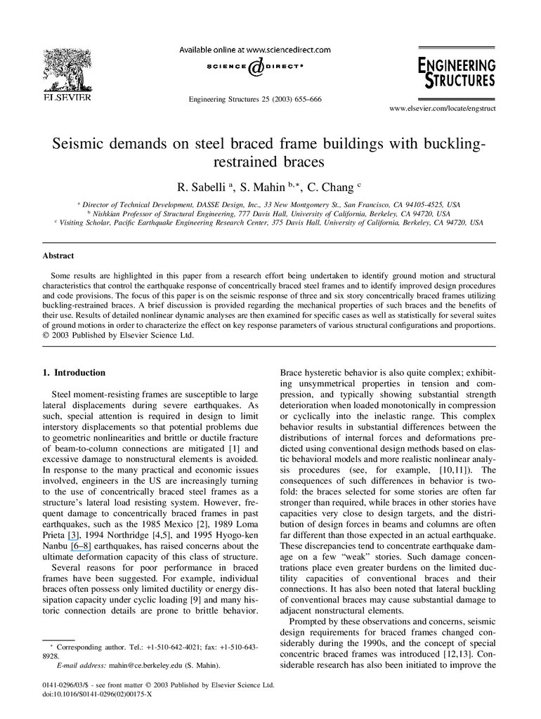
braces, high performance hysteretic braces, and viscoelastic dampers. Some of the basic structural configurations being studied are shown in Fig. 1. This paper
highlights results obtained for frames utilizing high performance hysteretic braces in which lateral and local
buckling is restrained.
2. Performance-based assessment of braced frames
In the development of new guidelines for steel
moment-resisting frames following the Northridge earthquake, the US Federal Emergency Management Agency
adopted a performance-based seismic-resistant design
approach [19]. In this methodology, performance levels
are stipulated in terms of the performance goal (the
degree of damage) and the seismic hazard level
(severity) for which the structure is expected to attain
this goal. A key advance in the new FEMA methodology
is that uncertainties and randomness in the seismic hazard, structural response, analytical procedures and modeling, and system and member level capacities are
accounted for explicitly. Based on this reliability framework, the methodology quantifies the confidence that the
structure will not exceed the targeted performance level.
In the case of new construction, emphasis is placed on
life safety and collapse prevention (though the method
provides for voluntary consideration of other performance levels, such as continued occupancy). Based on
calibrations to current design practices and expert opinion, FEMA has suggested that new steel moment
frames be able to attain for a seismic hazard corresponding to a 2% probability of exceedence in a 50 year time
period, at least a 90% confidence of avoiding behavior
modes that would jeopardize global stability of the structure, and a 50% confidence of avoiding local collapse
modes.
This performance-based evaluation framework permits comparison of the seismic performance of different
types of structural system on a consistent basis, and the
development of new design provisions that would provide uniform levels of reliability for different structural
systems, design and analysis methods, seismic hazards,
etc. To undertake such a study, the seismic demands
need to be first quantified for various hazard levels and
these are then compared with capacities. In this paper,
some of the structural and ground motion characteristics
affecting seismic demands of braced frames having
buckling-restrained braces are examined. Future publications will address issues related to the capacity assessment of such frames and the performance-based design
of concentrically braced frames in general.
3. Buckling-restrained braces
Fig. 1.
Some of the basic structural configurations being studied.
Since many of the potential performance difficulties
associated with conventional concentrically braced
frames rise from the difference between the tensile and
compression capacity of the brace, and the degradation
of brace capacity under compressive and cyclic loading,
considerable research has been devoted to development
of braces which exhibit more ideal elasto-plastic
behavior. One means of achieving this ideal behavior is
3.
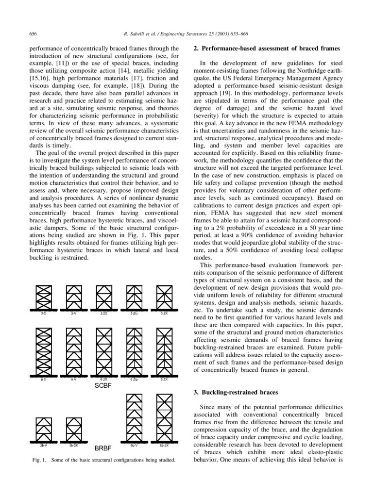
R. Sabelli et al. / Engineering Structures 25 (2003) 655–666Fig. 2.
657
Some schematic details used for buckling restrained braces [20].
through metallic yielding, where buckling in compression is restrained by an external mechanism. A number of approaches to accomplish this have been suggested (see Fig. 2) including enclosing a ductile metal
(usually steel) core (rectangular or cruciform plates, circular rods, etc.) in a continuous concrete filled steel tube,
within a continuous steel tube, a steel tube with intermittent stiffening fins, and so on. The assembly is detailed
so that the central yielding core can deform longitudinally independent from the mechanism that restrains lateral and local buckling. Through appropriate selection
of the strength of the material, and the areas and lengths
of the portions of the core that are expected to remain
elastic and to yield, a wide range of brace stiffness and
strength can be attained. Since lateral and local buckling
behavior modes are restrained, large inelastic capacities
are attainable. Theoretically based methods have been
developed to design the restraining media [21,22]. Provisions have been developed in draft form [23] for
design, specification and testing of buckling-restrained
braces to help insure braces meet performance expectations.
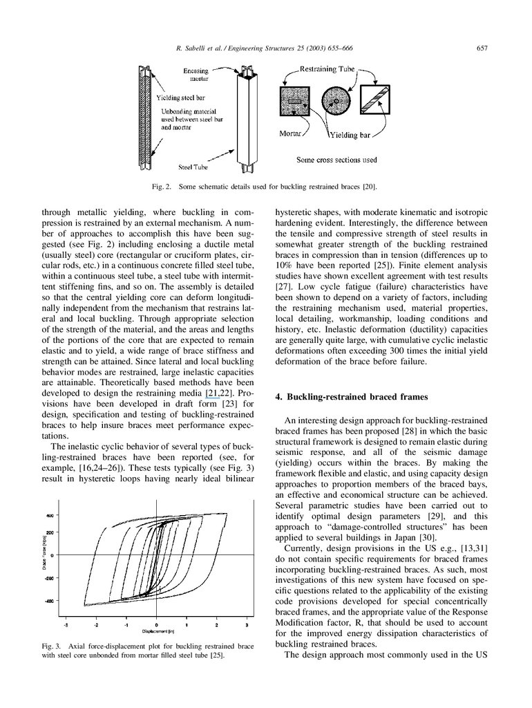
The inelastic cyclic behavior of several types of buckling-restrained braces have been reported (see, for
example, [16,24–26]). These tests typically (see Fig. 3)
result in hysteretic loops having nearly ideal bilinear
Fig. 3. Axial force-displacement plot for buckling restrained brace
with steel core unbonded from mortar filled steel tube [25].
hysteretic shapes, with moderate kinematic and isotropic
hardening evident. Interestingly, the difference between
the tensile and compressive strength of steel results in
somewhat greater strength of the buckling restrained
braces in compression than in tension (differences up to
10% have been reported [25]). Finite element analysis
studies have shown excellent agreement with test results
[27]. Low cycle fatigue (failure) characteristics have
been shown to depend on a variety of factors, including
the restraining mechanism used, material properties,
local detailing, workmanship, loading conditions and
history, etc. Inelastic deformation (ductility) capacities
are generally quite large, with cumulative cyclic inelastic
deformations often exceeding 300 times the initial yield
deformation of the brace before failure.
4. Buckling-restrained braced frames
An interesting design approach for buckling-restrained
braced frames has been proposed [28] in which the basic
structural framework is designed to remain elastic during
seismic response, and all of the seismic damage
(yielding) occurs within the braces. By making the
framework flexible and elastic, and using capacity design
approaches to proportion members of the braced bays,
an effective and economical structure can be achieved.
Several parametric studies have been carried out to
identify optimal design parameters [29], and this
approach to “damage-controlled structures” has been
applied to several buildings in Japan [30].
Currently, design provisions in the US e.g., [13,31]
do not contain specific requirements for braced frames
incorporating buckling-restrained braces. As such, most
investigations of this new system have focused on specific questions related to the applicability of the existing
code provisions developed for special concentrically
braced frames, and the appropriate value of the Response
Modification factor, R, that should be used to account
for the improved energy dissipation characteristics of
buckling restrained braces.
The design approach most commonly used in the US
4.
658R. Sabelli et al. / Engineering Structures 25 (2003) 655–666
for the design of buckling-restrained braced frames is
similar to that used for special concentrically braced
frame system [12]. However, buckling-restrained braces
are assumed to yield in a highly ductile manner, in both
compression and tension. They are usually characterized
by a full, stable, symmetric hysteretic loop with relatively low post-yield stiffness. As such, the redistribution
of loads and deformations in braced frames with buckling-restrained braces should be far less than with conventional braces. The fabrication of the brace cores from
plate stock also permits the designer to stipulate a specific capacity; thus, story capacities can be much closer
to the demands considered in design than possible with
conventional braces, thereby mitigating the tendency of
conventional bracing systems to concentrate damage in
weak stories. Since the braces do not buckle laterally,
local damage to adjacent nonstructural elements should
be substantially reduced.
The qualities of buckling-restrained braces, while generally considered desirable, raise some questions as well.
For instance, the low post-yield tangent stiffness of the
braces might lead to the concentration of damage in one
level even though brace capacities are relatively well
balanced with demands over the height of the structure,
thereby necessitating design provisions related to secondary lateral structural stiffness (to be provided by
structural framing or another mechanism) or a restriction
on the relative over-strength permitted in adjacent stories. Similarly, the difference between the tensile and
compressive capacities of the braces, while far less than
that typically encountered in concentric braced frames,
raises issues related to the design of the beams in chevron- (or V-) braced configurations. Similarly, the ability
of the designer to closely specify brace strength has
raised some concerns that the actual over-strength of
such frames may become sufficiently low that significant
yielding might occur under frequent ground motions
under which continued occupancy might be expected
(say, for excitations with a 50% probability of exceedence in 50 years).
To address these issues, several investigators have
carried out inelastic dynamic analyses of hypothetical
systems
containing
buckling-restrained
braces
[32,33,20]. Most of the design-oriented studies to date
have focused on adaptations of a three-story frame
model building developed to assess new design guidelines for steel moment frames [34]. To date, only a limited number of bracing configurations and ground
motions have been considered in these studies. Detailed
analyses have also been performed to examine the
behavior of buckling-restrained braces within a braced
frame system [35]. In all of these studies, the seismic
performance has been characterized as excellent and
additional research was encouraged to examine more
fully issues such as those identified above. Clearly, statistical information on system demands such as interstory
drifts, and brace demands such as maximum and cumulative inelastic deformations, are needed to characterize
performance and to develop test protocols for establishing brace qualification criteria and test protocols [23].
In this investigation, a series of model buildings were
designed and their response to a large number of earthquake ground motions representing various seismic hazard levels were numerically simulated.
5. Model buildings
To assess the performance of concentrically braced
frames, a series of three- and six-story braced frame
buildings were designed for a site in metropolitan Los
Angeles. The buildings were designed according to the
1997 NEHRP Recommended Provisions for Seismic
Regulations for New Buildings and Other Structures
(FEMA 302/303) [31]. This work is currently being
extended to include nine- and 20-story braced frame
structures. The building configurations and non-seismic
loading conditions were identical to those utilized in the
development of the FEMA 350 guidelines for moment
resisting frames, so that comparisons to moment frame
behavior could be made [6].
A variety of configurations of special concentrically
braced frame configurations were considered, for both
conventional and buckling-restrained braces (Fig. 1).
Results are presented here only for systems with buckling-restrained braces oriented in a stacked chevron
(inverted V-) pattern. In the design, buckling-restrained
braces were envisioned as having an unbonded, yielding
steel core within a mortar filled steel tube. However, the
design would be similar for nearly any buckling
restrained brace having equivalent properties. A572
Gr.50 steel was assumed in the design of all beams
and columns.
The three-story building design follows the design criteria used for the FEMA model buildings exactly [36].
It has a typical 13-foot (4 m) story-height. Its nominal
dimensions are 124 feet × 184 feet (37.8 m × 56.1m) in
plan; 30-foot (9.1 m) bays are employed in each direction. Floors and roof have a 3-inch (76-mm) metal deck
with normal-weight concrete topping. A small mechanical penthouse is provided. There are eight bays of bracing, four in each direction; the number of braced bays
was set to prevent an increase in member design forces
due to the Redundancy/Reliability factor, ρ, provided in
the building code for systems with a limited number of
lateral load resisting elements. The braced bays are
located on the perimeter of the building, in non-adjacent
bays. The columns are continuous for their full height.
While these assumptions are not atypical, they were
intentionally chosen in order to minimize system overstrength, so that conservative estimates of deformation
demands could be obtained from the response simulations.
5.
R. Sabelli et al. / Engineering Structures 25 (2003) 655–666The six-story building design is adapted from the
FEMA nine-story tall model building. This height structure was added to the example studies, as it is a very
common height for braced frame structures in the western US. The six story building has a typical 13-foot (4
m) story-height, but with an 18 feet (5.5 m) height at
the first story. Its nominal plan dimensions are 154
feet × 154 feet (46.9m × 46.9 m); 30 - foot × 30 foot (9.1 m × 9.1 m) bays are again employed. Floors
and roof have a 3-inch (76-mm) metal deck with normalweight concrete topping. A small penthouse is located
on the roof. Twelve bays of bracing are provided; six in
each direction. Again, the number of braced bays was
selected to prevent an increase in member design forces
due to the ρ factor. The braced bays are positioned along
the perimeter in non-adjacent bays. Both frame and nonframe columns are spliced at the fourth story.
In the design of the model buildings using FEMA
302/303, the equivalent static lateral force procedure was
employed based on a response-spectrum corresponding
to a hazard of 10% chance of exceedence in a 50-year
period. A Response Modification Factor (R) of six was
considered; a parallel design was also done using a
Response Modification Factor of eight. A System Overstrength Factor (⍀o) of 2 was used. Since code displacement criteria were not expected to control the design of
these systems, and the Deflection Amplification Factor
(Cd) remains to be defined for these systems at the time
of writing, drifts under static design forces were calculated, but not used to proportion member sizes. The
buildings were designed consistent with Seismic Use
Group I and Seismic Design Category D with an Importance Factor of 1.0. Site Class D (firm soil) was used for
determining the response spectrum in conjunction with
acceleration data obtained from seismic hazard maps
prepared by the US Geological Survey. For the determination of design forces, the building period and the force
distribution over the building height was determined
using the approximate methods provided in the provisions (where period is based on building height, and
lateral forces are distributed in proportion to elevation),
rather than by employing a more realistic dynamic analysis.
Beams connected to braces at their mid-span were
designed for the maximum expected unbalance force
from the braces. Based on earlier tests [20], the compression strength was assumed to be 10% larger than
the strength in tension. In order to capture the greatest
demands on the braces and beams, very flexible beams
were used. An alternate six-story model design was also
considered using stiffer beams designed to limit the vertical deflection under the maximum unbalance load.
Frame columns were designed using the ⍀o overstrength amplification factor applied to forces rather than
computing the maximum forces that could be delivered
to the frame system based on the actual capacity of the
659
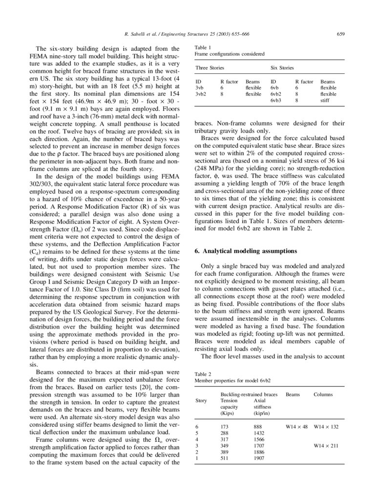
Table 1
Frame configurations considered
Three Stories
ID
3vb
3vb2
R factor
6
8
Six Stories
Beams
flexible
flexible
ID
6vb
6vb2
6vb3
R factor
6
8
8
Beams
flexible
flexible
stiff
braces. Non-frame columns were designed for their
tributary gravity loads only.
Braces were designed for the force calculated based
on the computed equivalent static base shear. Brace sizes
were set to within 2% of the computed required crosssectional area (based on a nominal yield stress of 36 ksi
(248 MPa) for the yielding core); no strength-reduction
factor, φ, was used. The brace stiffness was calculated
assuming a yielding length of 70% of the brace length
and cross-sectional area of the non-yielding zone of three
to six times that of the yielding zone; this is consistent
with current design practice. Analytical results are discussed in this paper for the five model building configurations listed in Table 1. Sizes of members determined for model 6vb2 are shown in Table 2.
6. Analytical modeling assumptions
Only a single braced bay was modeled and analyzed
for each frame configuration. Although the frames were
not explicitly designed to be moment resisting, all beam
to column connections with gusset plates attached (i.e.,
all connections except those at the roof) were modeled
as being fixed. Possible contributions of the floor slabs
to the beam stiffness and strength were ignored. Beams
were assumed inextensible in the analyses. Columns
were modeled as having a fixed base. The foundation
was modeled as rigid; footing up-lift was not permitted.
Braces were modeled as ideal members capable of
resisting axial loads only.
The floor level masses used in the analysis to account
Table 2
Member properties for model 6vb2
Story
6
5
4
3
2
1
Buckling-restrained braces
Tension
Axial
capacity
stiffness
(Kips)
(kip/in)
Beams
Columns
173
288
317
349
389
511
W14 × 48
W14 × 132
888
1432
1566
1707
1886
1907
W14 × 211
6.
660R. Sabelli et al. / Engineering Structures 25 (2003) 655–666
for horizontally acting inertia forces was taken as the
total mass of the each floor divided by the number of
braced bays used in the building in each principal direction. Global P-⌬ effects were considered based on this
mass. Since only horizontal ground excitations were
considered, local tributary masses were not distributed
along the floors. An effective viscous damping coefficient of 5% was assumed, according to common practice for code designed steel structures.
The analytical model included a single additional column member running the full height of the structure.
This column was intended to approximate the contributions of the gravity load framing to the lateral stiffness
of the structure. While this column provides little overall
resistance to lateral loads, it is expected to help redistribute loads across a story if localized yielding occurs in
that story. Since the connections of a beam to a column
in the gravity-only load resisting system were assumed
pinned, only the properties of the columns were included
to model the lateral stiffness of the gravity system. In
the analysis, the equivalent column was constrained to
have the same lateral displacement as the braced bent.
As a simplification, the equivalent column was given a
moment of inertia and moment capacity equal to the sum
of the corresponding values for all of the columns in
the gravity-only frames divided by the number of braced
frames oriented along the principal axes of the building
being analyzed.
The analyses were carried out using the nonlinear
dynamic analysis computer program SNAP-2DX [37].
The buckling-restrained braces were modeled using
element type 1 (a simple truss element with ideal bilinear
hysteretic behavior, exhibiting no stiffness or strength
degradation). In order to clarify the potential consequences of the nearly elasto-perfectly plastic hysteretic
characteristics of the buckling-restrained braces considered on the formation of weak story mechanisms, the
secondary post-yield stiffness of braces was set to zero.
To maximize demands on the braces and beams, the tension capacity was calculated from the cross-sectional
area assuming no material over-strength; the compression capacity was set to 110% of the tension
capacity. Beams and columns were modeled using
element type 2 (a beam-column element allowing axial
load-bending moment interaction, but with no stiffness
or strength degradation).
7. Earthquake ground motions
The models were analyzed using suites of ground
motions developed previously by Somerville and others
for use in the FEMA project on steel moment-resisting
frames [38,39]. These suites consist of 20 horizontal
ground acceleration records (two components for each of
ten physical sites) adjusted so that their mean response
spectrum matches the 1997 NEHRP design spectrum (as
modified from soil type of SB-SC to soil type SD and
having a hazard specified by the 1997 USGS maps for
downtown Los Angeles). For this study, the earthquake
suites corresponding to downtown Los Angeles, California, were selected for seismic hazard levels corresponding to a 50, 10 and 2% probability of exccedence in a
50-year period. These acceleration time histories were
derived from historical recordings or from simulations
of physical fault rupture processes. The two horizontal
components of the original records were initially
resolved into fault-normal and fault-parallel orientations.
The records were adjusted in the frequency domain to
have characteristics appropriate for NEHRP SD soil sites.
The records were further amplitude scaled so that the
average spectral ordinate for the two horizontal components matched the target spectrum. The individual
components were lastly rotated 45 degrees away from
the fault-normal/fault-parallel orientations to avoid
excessive near-fault directivity effects biasing individual
analyses. A separate study of near-fault effects on braced
frames is underway.
8. Case study example
In this section, the response results for a six story
braced frame model, designed with an R factor of eight
(Model 6vb2) are described in detail for the specific case
of one of the records in the 10% in 50-year hazard suite.
The record in question is designated LA20, and was
derived from a near-fault site during a moderate magnitude event, the 1986 North Palm Springs earthquake. For
the 10% in 50-year probability of exceedence, this record has been amplitude scaled to 0.98 g. For this severe
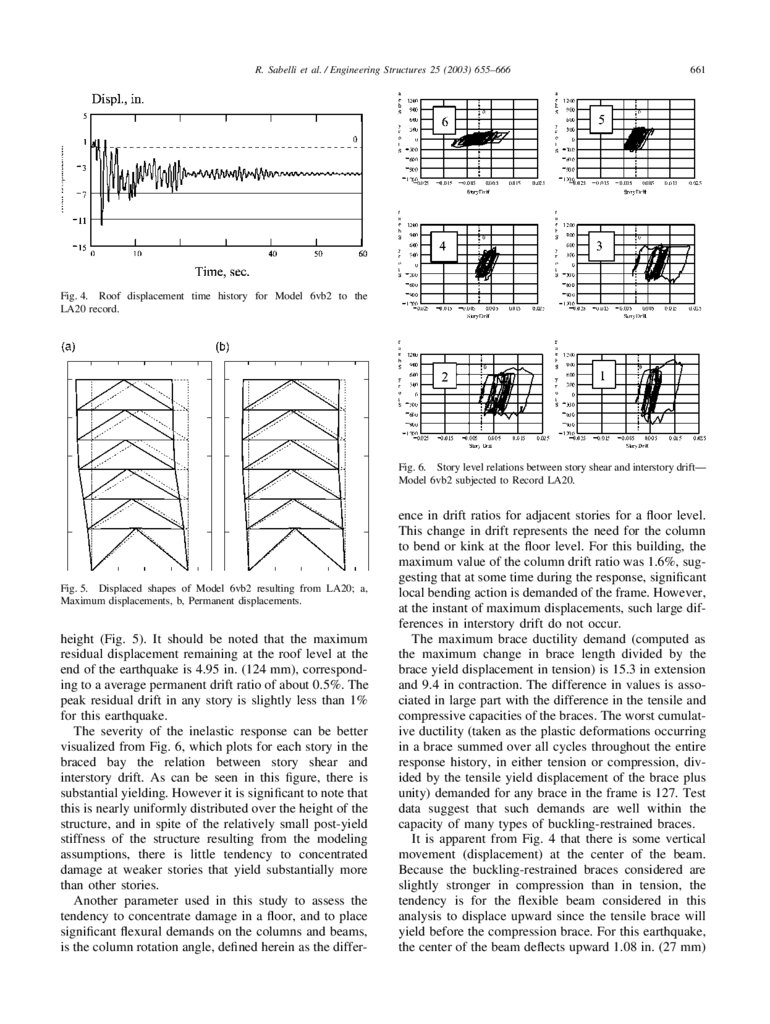
record, the peak roof displacement computed is 11.93
in. (300 mm), corresponding to an average maximum
interstory drift of only about 1.2%. The maximum
interstory drift ratio that occurs at any level during the
earthquake is 2.3%, suggesting that some concentration
of damage occurs within one or more stories. The permanent displacement offset that can be seen in the roof level
displacement time history (Fig. 4) suggests that considerable inelastic action does occur during this earthquake. As will be elaborated on in the next section, peak
roof displacements ranged from 5.48 to 16.6 in (140–
422 mm) for the records considered in this suite; averaging 9.74 in (247 mm). Thus, the response to this record
LA20 is well above average.
An examination of the displaced shape of the building
when the maximum roof response occurs (Fig. 5) suggests a relatively uniform distribution of interstory drift
over the height, with higher than average drifts in the
lower three stories, and lower than average values in the
upper three stories. Similarly, the residual displacements
retained in the structure are nearly uniform over the full
7.
R. Sabelli et al. / Engineering Structures 25 (2003) 655–666661
Fig. 4. Roof displacement time history for Model 6vb2 to the
LA20 record.
Fig. 6. Story level relations between story shear and interstory drift—
Model 6vb2 subjected to Record LA20.
Fig. 5. Displaced shapes of Model 6vb2 resulting from LA20; a,
Maximum displacements, b, Permanent displacements.
height (Fig. 5). It should be noted that the maximum
residual displacement remaining at the roof level at the
end of the earthquake is 4.95 in. (124 mm), corresponding to a average permanent drift ratio of about 0.5%. The
peak residual drift in any story is slightly less than 1%
for this earthquake.
The severity of the inelastic response can be better
visualized from Fig. 6, which plots for each story in the
braced bay the relation between story shear and
interstory drift. As can be seen in this figure, there is
substantial yielding. However it is significant to note that
this is nearly uniformly distributed over the height of the
structure, and in spite of the relatively small post-yield
stiffness of the structure resulting from the modeling
assumptions, there is little tendency to concentrated
damage at weaker stories that yield substantially more
than other stories.
Another parameter used in this study to assess the
tendency to concentrate damage in a floor, and to place
significant flexural demands on the columns and beams,
is the column rotation angle, defined herein as the differ-
ence in drift ratios for adjacent stories for a floor level.
This change in drift represents the need for the column
to bend or kink at the floor level. For this building, the
maximum value of the column drift ratio was 1.6%, suggesting that at some time during the response, significant
local bending action is demanded of the frame. However,
at the instant of maximum displacements, such large differences in interstory drift do not occur.
The maximum brace ductility demand (computed as
the maximum change in brace length divided by the
brace yield displacement in tension) is 15.3 in extension
and 9.4 in contraction. The difference in values is associated in large part with the difference in the tensile and
compressive capacities of the braces. The worst cumulative ductility (taken as the plastic deformations occurring
in a brace summed over all cycles throughout the entire
response history, in either tension or compression, divided by the tensile yield displacement of the brace plus
unity) demanded for any brace in the frame is 127. Test
data suggest that such demands are well within the
capacity of many types of buckling-restrained braces.
It is apparent from Fig. 4 that there is some vertical
movement (displacement) at the center of the beam.
Because the buckling-restrained braces considered are
slightly stronger in compression than in tension, the
tendency is for the flexible beam considered in this
analysis to displace upward since the tensile brace will
yield before the compression brace. For this earthquake,
the center of the beam deflects upward 1.08 in. (27 mm)
8.
662R. Sabelli et al. / Engineering Structures 25 (2003) 655–666
(and only 0.01 in. (0.3 mm) downward). While this is a
small displacement over the 30 ft (9 m) span of the
beam, nearly 90% of the peak value remains after the
earthquake, and it represents a large fraction (about 2/3)
of the worst interstory drift developed at any level. It
should be noted that the braces were intentionally modeled to maximize this behavior. Inclusion of more
realistic beam and brace properties would be expected
to reduce this vertical movement. Results of a companion study [32] demonstrate the effectiveness of double story X-bracing configurations (see Fig. 1) in reducing this movement.
9. Statistical evaluation of seismic demands on
buckling restrained braced frames
Because there is considerable variation in response
from record to record, and since the records considered
in these analyses were not selected to represent a particular type of earthquake, but rather a range of earthquake
events that might occur at the building site over a long
period of time, it is important to examine the results in
a statistical sense as well as on a case by case basis. For
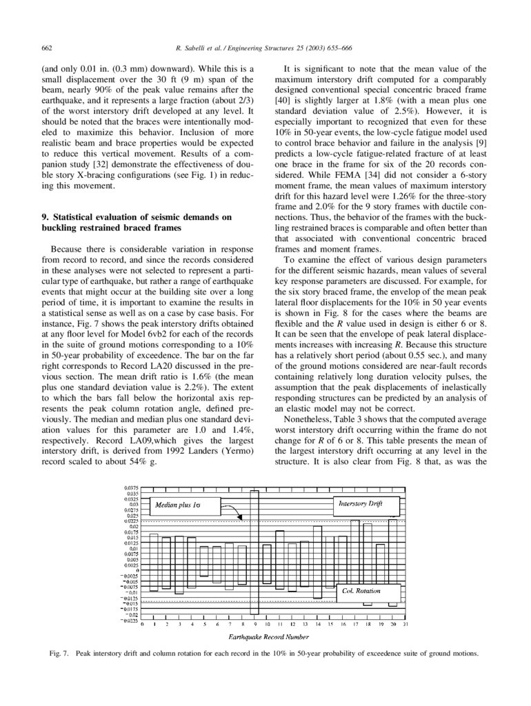
instance, Fig. 7 shows the peak interstory drifts obtained
at any floor level for Model 6vb2 for each of the records
in the suite of ground motions corresponding to a 10%
in 50-year probability of exceedence. The bar on the far
right corresponds to Record LA20 discussed in the previous section. The mean drift ratio is 1.6% (the mean
plus one standard deviation value is 2.2%). The extent
to which the bars fall below the horizontal axis represents the peak column rotation angle, defined previously. The median and median plus one standard deviation values for this parameter are 1.0 and 1.4%,
respectively. Record LA09,which gives the largest
interstory drift, is derived from 1992 Landers (Yermo)
record scaled to about 54% g.
Fig. 7.
It is significant to note that the mean value of the
maximum interstory drift computed for a comparably
designed conventional special concentric braced frame
[40] is slightly larger at 1.8% (with a mean plus one
standard deviation value of 2.5%). However, it is
especially important to recognized that even for these
10% in 50-year events, the low-cycle fatigue model used
to control brace behavior and failure in the analysis [9]
predicts a low-cycle fatigue-related fracture of at least
one brace in the frame for six of the 20 records considered. While FEMA [34] did not consider a 6-story
moment frame, the mean values of maximum interstory
drift for this hazard level were 1.26% for the three-story
frame and 2.0% for the 9 story frames with ductile connections. Thus, the behavior of the frames with the buckling restrained braces is comparable and often better than
that associated with conventional concentric braced
frames and moment frames.
To examine the effect of various design parameters
for the different seismic hazards, mean values of several
key response parameters are discussed. For example, for
the six story braced frame, the envelop of the mean peak
lateral floor displacements for the 10% in 50 year events
is shown in Fig. 8 for the cases where the beams are
flexible and the R value used in design is either 6 or 8.
It can be seen that the envelope of peak lateral displacements increases with increasing R. Because this structure
has a relatively short period (about 0.55 sec.), and many
of the ground motions considered are near-fault records
containing relatively long duration velocity pulses, the
assumption that the peak displacements of inelastically
responding structures can be predicted by an analysis of
an elastic model may not be correct.
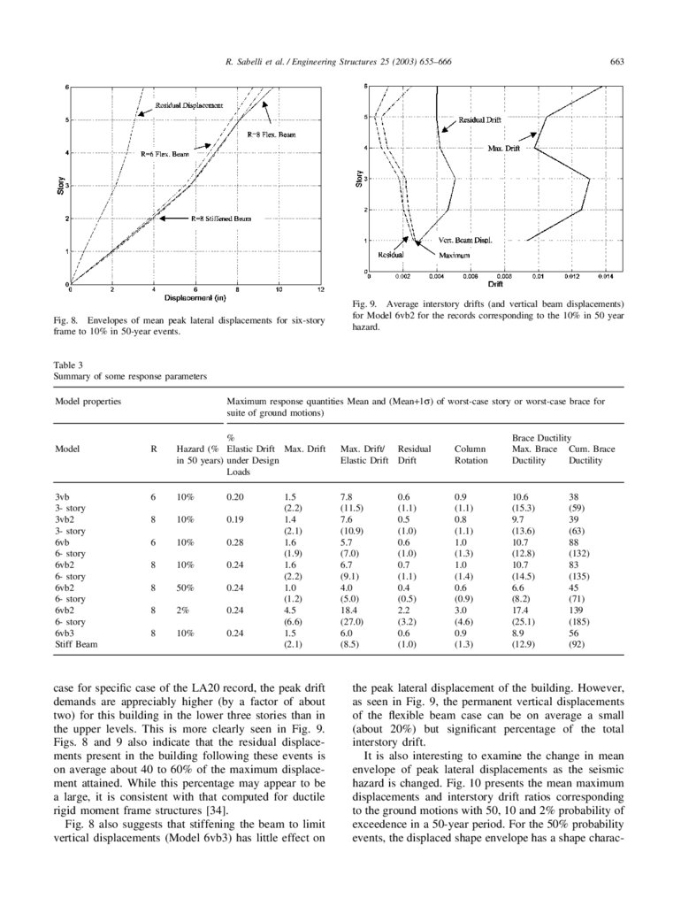
Nonetheless, Table 3 shows that the computed average
worst interstory drift occurring within the frame do not
change for R of 6 or 8. This table presents the mean of
the largest interstory drift occurring at any level in the
structure. It is also clear from Fig. 8 that, as was the
Peak interstory drift and column rotation for each record in the 10% in 50-year probability of exceedence suite of ground motions.
9.
R. Sabelli et al. / Engineering Structures 25 (2003) 655–666Fig. 8. Envelopes of mean peak lateral displacements for six-story
frame to 10% in 50-year events.
663
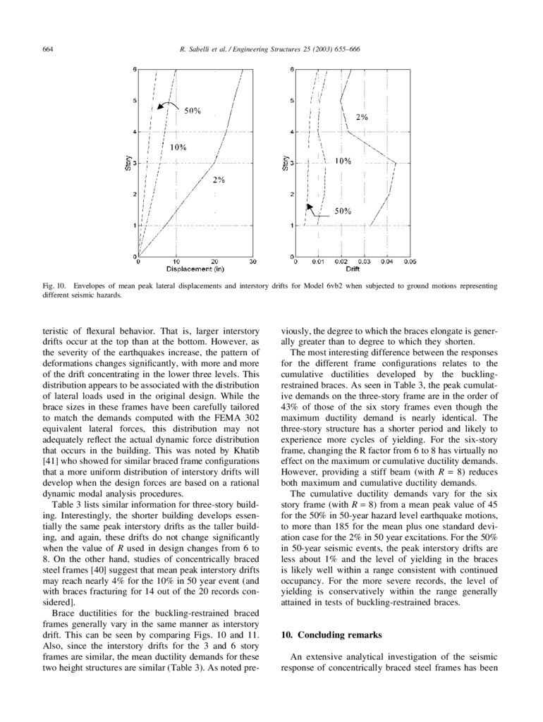
Fig. 9. Average interstory drifts (and vertical beam displacements)
for Model 6vb2 for the records corresponding to the 10% in 50 year
hazard.
Table 3
Summary of some response parameters
Model properties
Maximum response quantities Mean and (Mean+1σ) of worst-case story or worst-case brace for
suite of ground motions)
%
Hazard (% Elastic Drift Max. Drift
in 50 years) under Design
Loads
Model
R
3vb
3- story
3vb2
3- story
6vb
6- story
6vb2
6- story
6vb2
6- story
6vb2
6- story
6vb3
Stiff Beam
6
10%
0.20
8
10%
0.19
6
10%
0.28
8
10%
0.24
8
50%
0.24
8
2%
0.24
8
10%
0.24
1.5
(2.2)
1.4
(2.1)
1.6
(1.9)
1.6
(2.2)
1.0
(1.2)
4.5
(6.6)
1.5
(2.1)
case for specific case of the LA20 record, the peak drift
demands are appreciably higher (by a factor of about
two) for this building in the lower three stories than in
the upper levels. This is more clearly seen in Fig. 9.
Figs. 8 and 9 also indicate that the residual displacements present in the building following these events is
on average about 40 to 60% of the maximum displacement attained. While this percentage may appear to be
a large, it is consistent with that computed for ductile
rigid moment frame structures [34].
Fig. 8 also suggests that stiffening the beam to limit
vertical displacements (Model 6vb3) has little effect on
Max. Drift/ Residual
Elastic Drift Drift
Column
Rotation
Brace Ductility
Max. Brace Cum. Brace
Ductility
Ductility
7.8
(11.5)
7.6
(10.9)
5.7
(7.0)
6.7
(9.1)
4.0
(5.0)
18.4
(27.0)
6.0
(8.5)
0.9
(1.1)
0.8
(1.1)
1.0
(1.3)
1.0
(1.4)
0.6
(0.9)
3.0
(4.6)
0.9
(1.3)
10.6
(15.3)
9.7
(13.6)
10.7
(12.8)
10.7
(14.5)
6.6
(8.2)
17.4
(25.1)
8.9
(12.9)
0.6
(1.1)
0.5
(1.0)
0.6
(1.0)
0.7
(1.1)
0.4
(0.5)
2.2
(3.2)
0.6
(1.0)
38
(59)
39
(63)
88
(132)
83
(135)
45
(71)
139
(185)
56
(92)
the peak lateral displacement of the building. However,
as seen in Fig. 9, the permanent vertical displacements
of the flexible beam case can be on average a small
(about 20%) but significant percentage of the total
interstory drift.
It is also interesting to examine the change in mean
envelope of peak lateral displacements as the seismic
hazard is changed. Fig. 10 presents the mean maximum
displacements and interstory drift ratios corresponding
to the ground motions with 50, 10 and 2% probability of
exceedence in a 50-year period. For the 50% probability
events, the displaced shape envelope has a shape charac-
10.
664R. Sabelli et al. / Engineering Structures 25 (2003) 655–666
Fig. 10. Envelopes of mean peak lateral displacements and interstory drifts for Model 6vb2 when subjected to ground motions representing
different seismic hazards.
teristic of flexural behavior. That is, larger interstory
drifts occur at the top than at the bottom. However, as
the severity of the earthquakes increase, the pattern of
deformations changes significantly, with more and more
of the drift concentrating in the lower three levels. This
distribution appears to be associated with the distribution
of lateral loads used in the original design. While the
brace sizes in these frames have been carefully tailored
to match the demands computed with the FEMA 302
equivalent lateral forces, this distribution may not
adequately reflect the actual dynamic force distribution
that occurs in the building. This was noted by Khatib
[41] who showed for similar braced frame configurations
that a more uniform distribution of interstory drifts will
develop when the design forces are based on a rational
dynamic modal analysis procedures.
Table 3 lists similar information for three-story building. Interestingly, the shorter building develops essentially the same peak interstory drifts as the taller building, and again, these drifts do not change significantly
when the value of R used in design changes from 6 to
8. On the other hand, studies of concentrically braced
steel frames [40] suggest that mean peak interstory drifts
may reach nearly 4% for the 10% in 50 year event (and
with braces fracturing for 14 out of the 20 records considered].
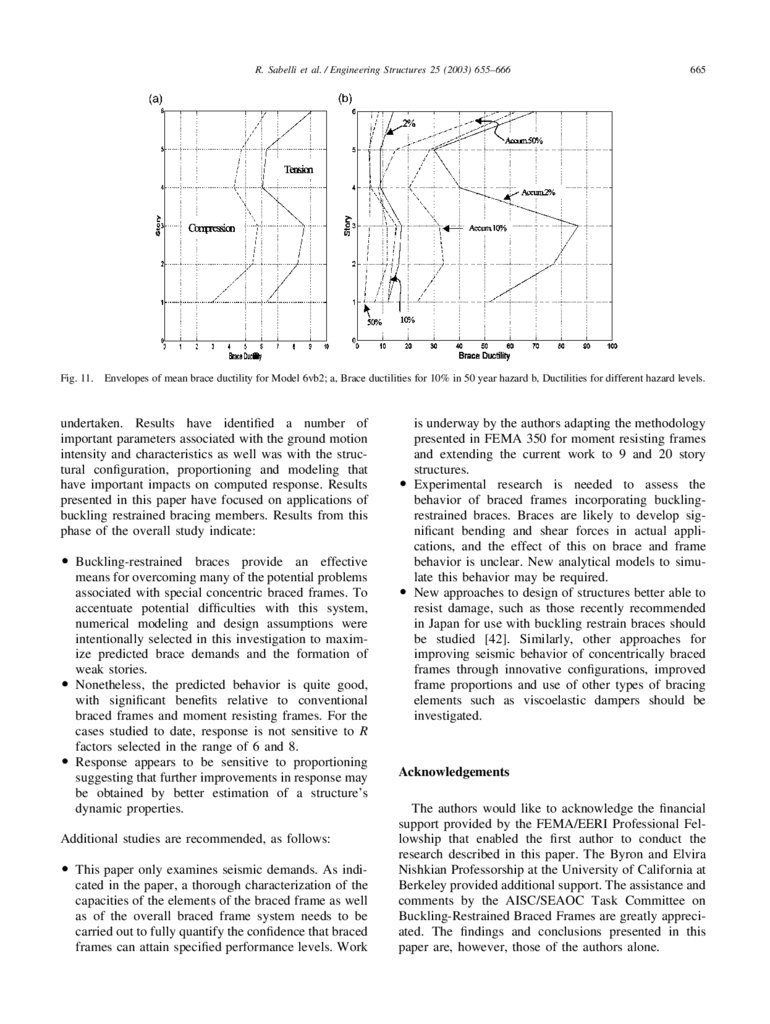
Brace ductilities for the buckling-restrained braced
frames generally vary in the same manner as interstory
drift. This can be seen by comparing Figs. 10 and 11.
Also, since the interstory drifts for the 3 and 6 story
frames are similar, the mean ductility demands for these
two height structures are similar (Table 3). As noted pre-
viously, the degree to which the braces elongate is generally greater than to degree to which they shorten.
The most interesting difference between the responses
for the different frame configurations relates to the
cumulative ductilities developed by the bucklingrestrained braces. As seen in Table 3, the peak cumulative demands on the three-story frame are in the order of
43% of those of the six story frames even though the
maximum ductility demand is nearly identical. The
three-story structure has a shorter period and likely to
experience more cycles of yielding. For the six-story
frame, changing the R factor from 6 to 8 has virtually no
effect on the maximum or cumulative ductility demands.
However, providing a stiff beam (with R = 8) reduces
both maximum and cumulative ductility demands.
The cumulative ductility demands vary for the six
story frame (with R = 8) from a mean peak value of 45
for the 50% in 50-year hazard level earthquake motions,
to more than 185 for the mean plus one standard deviation case for the 2% in 50 year excitations. For the 50%
in 50-year seismic events, the peak interstory drifts are
less about 1% and the level of yielding in the braces
is likely well within a range consistent with continued
occupancy. For the more severe records, the level of
yielding is conservatively within the range generally
attained in tests of buckling-restrained braces.
10. Concluding remarks
An extensive analytical investigation of the seismic
response of concentrically braced steel frames has been
11.
R. Sabelli et al. / Engineering Structures 25 (2003) 655–666665
Fig. 11. Envelopes of mean brace ductility for Model 6vb2; a, Brace ductilities for 10% in 50 year hazard b, Ductilities for different hazard levels.
undertaken. Results have identified a number of
important parameters associated with the ground motion
intensity and characteristics as well was with the structural configuration, proportioning and modeling that
have important impacts on computed response. Results
presented in this paper have focused on applications of
buckling restrained bracing members. Results from this
phase of the overall study indicate:
앫 Buckling-restrained braces provide an effective
means for overcoming many of the potential problems
associated with special concentric braced frames. To
accentuate potential difficulties with this system,
numerical modeling and design assumptions were
intentionally selected in this investigation to maximize predicted brace demands and the formation of
weak stories.
앫 Nonetheless, the predicted behavior is quite good,
with significant benefits relative to conventional
braced frames and moment resisting frames. For the
cases studied to date, response is not sensitive to R
factors selected in the range of 6 and 8.
앫 Response appears to be sensitive to proportioning
suggesting that further improvements in response may
be obtained by better estimation of a structure’s
dynamic properties.
Additional studies are recommended, as follows:
앫 This paper only examines seismic demands. As indicated in the paper, a thorough characterization of the
capacities of the elements of the braced frame as well
as of the overall braced frame system needs to be
carried out to fully quantify the confidence that braced
frames can attain specified performance levels. Work
is underway by the authors adapting the methodology
presented in FEMA 350 for moment resisting frames
and extending the current work to 9 and 20 story
structures.
앫 Experimental research is needed to assess the
behavior of braced frames incorporating bucklingrestrained braces. Braces are likely to develop significant bending and shear forces in actual applications, and the effect of this on brace and frame
behavior is unclear. New analytical models to simulate this behavior may be required.
앫 New approaches to design of structures better able to
resist damage, such as those recently recommended
in Japan for use with buckling restrain braces should
be studied [42]. Similarly, other approaches for
improving seismic behavior of concentrically braced
frames through innovative configurations, improved
frame proportions and use of other types of bracing
elements such as viscoelastic dampers should be
investigated.
Acknowledgements
The authors would like to acknowledge the financial
support provided by the FEMA/EERI Professional Fellowship that enabled the first author to conduct the
research described in this paper. The Byron and Elvira
Nishkian Professorship at the University of California at
Berkeley provided additional support. The assistance and
comments by the AISC/SEAOC Task Committee on
Buckling-Restrained Braced Frames are greatly appreciated. The findings and conclusions presented in this
paper are, however, those of the authors alone.
12.
666R. Sabelli et al. / Engineering Structures 25 (2003) 655–666
References
[1] FEMA, Recommended Seismic Design Provisions for New
Moment Frame Buildings Report FEMA 350, Federal Emergency
Management Agency, Washington DC, 2000.
[2] Osteraas J, Krawinkler H. The Mexico earthquake of September
19, 1985—behavior of steel buildings. Earthquake Spectra
1989;5(1):51–88.
[3] Kim H, Goel S. Seismic evaluation and upgrading of braced
frame structures for potential local failures. UMCEE 92-24, Dept.
of Civil Engineering and Environmental Engineering, Univ. of
Michigan, Ann Arbor, Oct. 1992, p.290.
[4] Tremblay R et al. Performance of steel structures during the 1994
Northridge earthquake. Canadian Journal of Civil Engineering
1995;22(2):338–60.
[5] Krawinkler H, et al. Northridge earthquake of January 17, 1994:
reconnaissance report, Vol. 2—steel buildings. Earthquake Spectra, 11, Suppl. C, Jan. 1996, p.25-47.
[6] Architectural Inst. of Japan, Steel Committee of Kinki Branch,
Reconnaissance report on damage to steel building structures
observed from the 1995 Hyogoken-Nanbu (Hanshin/Awaji)
earthquake), AIJ, Tokyo, May 1995, p.167.
[7] Hisatoku T. Reanalysis and repair of a high-rise steel building
damaged by the 1995 Hyogoken-Nanbu earthquake. Proceedings,
64th Annual Convention, Structural Engineers Association of
California, Structural Engineers Assn. of California, Sacramento,
CA, 1995, pages 21-40
[8] Tremblay R et al. Seismic design of steel buildings: lessons from
the 1995 Hyogo-ken Nanbu earthquake. Canadian Journal of
Civil Engineering 1996;23(3):727–56.
[9] Tang X, Goel SC. A fracture criterion for tubular bracing members and its application to inelastic dynamic analysis of braced
steel structures, Proceedings, Ninth World Conference on Earthquake Engineering, 9WCEE Organizing Committee, Japan Assn.
for Earthquake Disaster Prevention, Tokyo, Vol. IV, 1989, p.285290, Paper 6-3-14
[10] Jain A, Goel S. Seismic response of eccentric and concentric
braced steel frames with different proportions, UMEE 79R1,
Dept. of Civil Engineering, Univ. of Michigan, Ann Arbor, MI,
July 1979, p.88.
[11] Khatib I, Mahin S. Dynamic inelastic behavior of chevron braced
steel frames. Fifth Canadian Conference on Earthquake Engineering, Balkema, Rotterdam, 1987, p.211-220.
[12] AISC (American Institute of Steel Construction), Seismic provisions for structural steel buildings, Chicago, IL, 1997.
[13] ICBO (International Conference of Building Officials), Uniform
building code. Whittier, CA, 1997.
[14] Liu Z, Goel S. Investigation of concrete-filled steel tubes under
cyclic bending and buckling, Research Report UMCE 87-3. Dept.
of Civil Engineering, Univ. of Michigan, Ann Arbor, MI, Apr.
1987, p.226.
[16] Kamura H, Katayama T, Shimokawa H, Okamoto H. Energy dissipation characteristics of hysteretic dampers with low yield
strength steel. Proceedings, US–Japan Joint Meeting for
Advanced Steel Structures, Building Research Institute, Tokyo,
Nov. 2000.
[17] Ohi K, Shimawaki Y, Lee S, Otsuka H. Pseudodynamic tests on
pseudo-elastic bracing system made from shape memory alloy.
Bulletin of Earthquake Resistant Structure Research Center
2001;34:21–8.
[18] Aiken I et al. Comparative study of four passive energy dissipation systems, Bulletin of the New Zealand National Society for
Earthquake Engineering, 25, 3, Sept. 1992, p. 175-192.
[19] FEMA, State of the art report on performance prediction and
evaluation (FEMA-355F), Federal Emergency Management
Agency, Washington, DC, 2000.
[20] Clark P. et al. Large-scale testing of steel unbonded braces for
[21]
[22]
[23]
[24]
[25]
[26]
[29]
[30]
[31]
[32]
[33]
[35]
[36]
[37]
[38]
[40]
energy dissipation, advanced technology in structural engineering. Proceedings of the 2000 Structures Congress & Exposition,
May 8–10, 2000, Philadelphia, PA, American Society of Civil
Engineers, Reston, VA, 2000.
Yoshida K et al. Stiffness requirement of reinforced unbonded
brace cover. Journal of Structural and Construction Engineering
(Trans. of AIJ) 1999;521:141–7 in Japanese.
Yoshida K, Mitani I, Ando N. Shear force of reinforced unbonded
brace cover at its end, Composite and Hybrid Structures: Proceedings of the Sixth ASCCS International Conference on Steel-Concrete Composite Structures, Dept. of Civil Engineering, University of Southern California, Los Angeles, CA, Vol. 1, 2000,
p.371-376.
SEAOC (Structural Engineers Association of California), Draft
provisions for buckling-restrained braced frames, Sacramento,
CA, 2001.
Watanabe A, et al. Properties of brace encased in bucklingrestraining concrete and steel tube, Proceedings, Ninth World
Conference on Earthquake Engineering. 9WCEE Organizing
Committee, Japan Assn. for Earthquake Disaster Prevention,
Tokyo, Vol. IV, 1989, p.719-724, Paper 6-7-4.
Clark P. et al. Evaluation of design methodologies for structures
incorporating steel unbonded braces for energy dissipation, 12th
World Conference on Earthquake Engineering. Proceedings, New
Zealand Society for Earthquake Engineering, 2000, Paper No. 2240.
Iwata M, Kato T, Wada A. Buckling-restrained braces as hysteretic dampers, Behaviour of steel structures in seismic areas:
STESSA 2000, Balkema, 2000, p. 33-38.
Watanabe A. Some damage control criteria for a steel building
with added hysteresis damper. Eleventh World Conference on
Earthquake Engineering [Proceedings], Pergamon, Elsevier
Science Ltd., 1996, Disc 1, Paper No. 449.
Wada A, Huang Y. Damage-controlled structures in Japan,
PEER-1999/10. US–Japan Workshop on Performance-Based
Earthquake Engineering Methodology for Reinforced Concrete
Building Structures, 13 September 1999, Maui, HI, Berkeley,
CA: Pacific Earthquake Engineering Research Center, University
of California, Dec. 1999, p.279-289.
FEMA, 1997 NEHRP Recommended provisions for seismic
regulations for new buildings and other structures, Federal
Emergency Management Agency, Washington, DC, 1997.
Ku W. Nonlinear analyses of a three-story steel concentrically
braced frame building with the application of buckling-restrained
(unbonded) brace. Dept. of Civil and Environmental Engineering,
University of California, Berkeley, CA, 1999.
Huang Y. et al. Seismic performance of moment resistant steel
frame with hysteretic damper, Behaviour of Steel Structures in
Seismic Areas: STESSA 2000, A. A. Balkema, Rotterdam, 2000,
p. 403-409.
Saeki E, Iwamatu K, Wada A. Analytical study by finite element
method and comparison with experiment results concerning buckling-restrained unbonded braces. Journal of Structural and Construction Engineering (Trans. of AIJ) 1996;484:111–20.
MacRae G. Parametric study on the effect of ground motion
intensity and dynamic characteristics on seismic demands in steel
moment resisting frames. SAC Background Document SAC/BD99/01, SAC Joint Venture, Sacramento, CA, 1999.
Rai D, Goel S, Firmansjah J. SNAP-2DX (Structural Nonlinear
Analysis Program). Research Report UMCEE96-21. Dept. of
Civil Engineering, Univ. of Michigan, Ann Arbor, MI, 1996.
Somerville P, et al. Development of ground motion time histories
for phase 2, SAC Background Document SAC/BD-97/04, SAC
Joint Venture, Sacramento, CA, 1997.
Sabelli R, et al. Investigation of the nonlinear seismic response
of special concentric and buckling restrained braced frames and
implications for design. Report to EERI, FEMA/EERI Professional Fellowship Report, 2001 (in preparation).