


 Механика
Похожие презентации:


172 assembling drawing
1.
SINO367045Feasibility
Analysis Report
version NO.1
2017年
www.sinogroupe.com
2/22
1
2.
Product partwww.sinogroupe.com
2
3.
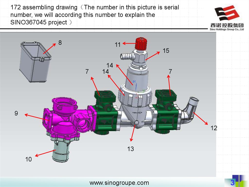
172 assembling drawing The number in this picture is serialnumber, we will according this number to explain the
SINO367045 project
8
11
15
7
14
14
7
9
12
13
10
www.sinogroupe.com
3
4.
172 assembling drawing The number in this picture is serialnumber, we will according this number to explain the
SINO367045 project
16
17
www.sinogroupe.com
4
5.
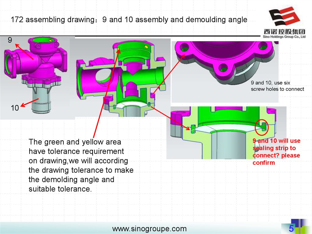
172 assembling drawing 9 and 10 assembly and demoulding angle9
9 and 10, use six
screw holes to connect
10
The green and yellow area
have tolerance requirement
on drawing,we will according
the drawing tolerance to make
the demolding angle and
suitable tolerance.
www.sinogroupe.com
9 and 10 will use
sealing strip to
connect? please
confirm
5
6.
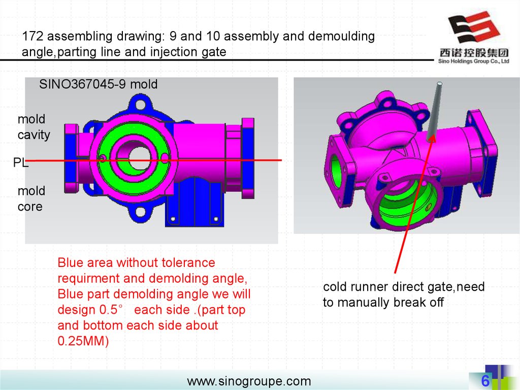
172 assembling drawing: 9 and 10 assembly and demouldingangle,parting line and injection gate
SINO367045-9 mold
mold
cavity
PL
mold
core
Blue area without tolerance
requirment and demolding angle,
Blue part demolding angle we will
design 0.5° each side .(part top
and bottom each side about
0.25MM)
www.sinogroupe.com
cold runner direct gate,need
to manually break off
6
7.
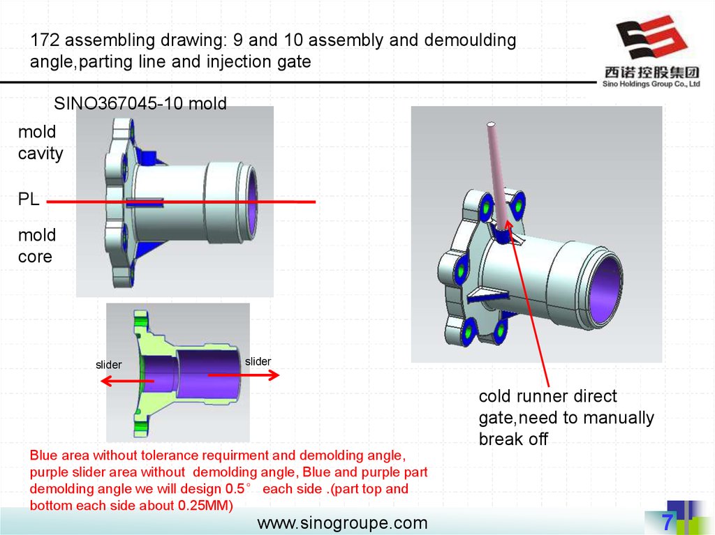
172 assembling drawing: 9 and 10 assembly and demouldingangle,parting line and injection gate
SINO367045-10 mold
mold
cavity
PL
mold
core
slider
slider
cold runner direct
gate,need to manually
break off
Blue area without tolerance requirment and demolding angle,
purple slider area without demolding angle, Blue and purple part
demolding angle we will design 0.5° each side .(part top and
bottom each side about 0.25MM)
www.sinogroupe.com
7
8.
172 assembling drawing: 7 and 9 and 13 assembly anddemoulding angle
13
9
7
7
The green and yellow part area have tolerance requirement
on drawing,we will according the drawing tolerance to make
the demolding angle and suitable tolerance.
www.sinogroupe.com
8
9.
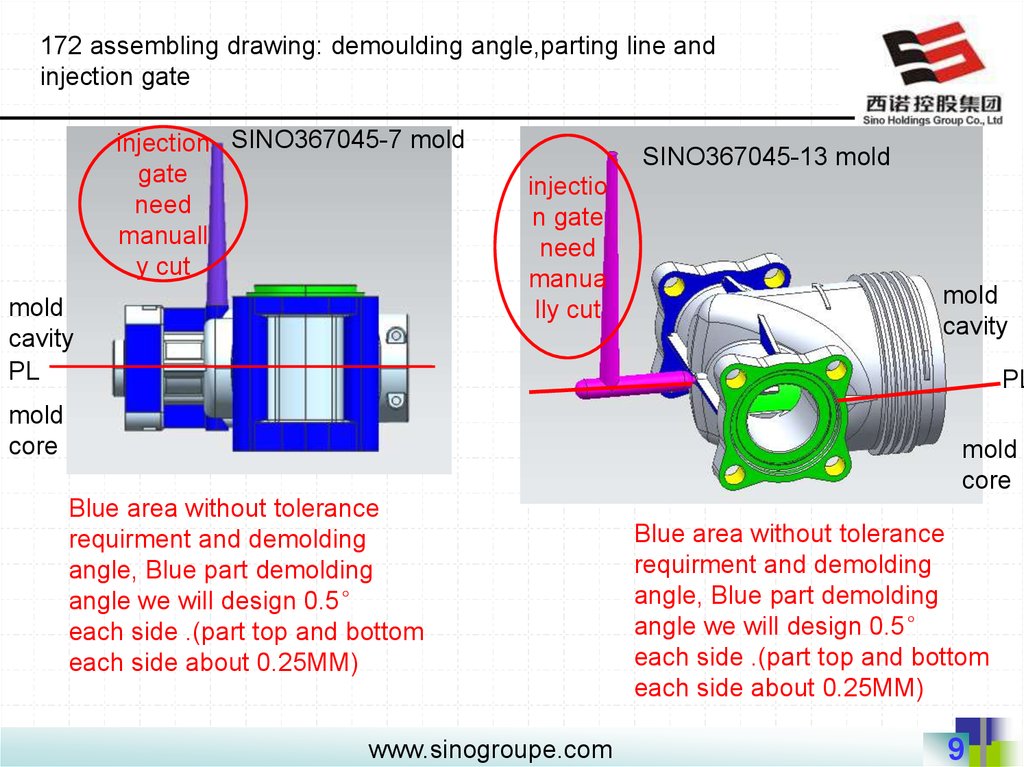
172 assembling drawing: demoulding angle,parting line andinjection gate
injection SINO367045-7 mold
gate
need
manuall
y cut
mold
cavity
PL
SINO367045-13 mold
injectio
n gate
need
manua
lly cut
mold
cavity
PL
mold
core
mold
core
Blue area without tolerance
requirment and demolding
angle, Blue part demolding
angle we will design 0.5°
each side .(part top and bottom
each side about 0.25MM)
www.sinogroupe.com
Blue area without tolerance
requirment and demolding
angle, Blue part demolding
angle we will design 0.5°
each side .(part top and bottom
each side about 0.25MM)
9
10.
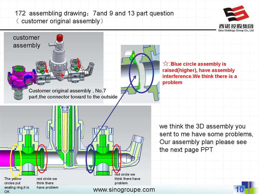
172 assembling drawing 7and 9 and 13 part questioncustomer original assembly
customer
assembly
☆:Blue circle assembly is
raised(higher), have assembly
interference.We think there is a
problem
Customer original assembly , No.7
part,the connector toward to the outside
we think the 3D assembly you
sent to me have some problems,
Our assembly plan please see
the next page PPT
The yellow
circles put
sealing ring,it is
OK
red circle we
think there
have problem
red circle we
think there have
problem
www.sinogroupe.com
10
11.
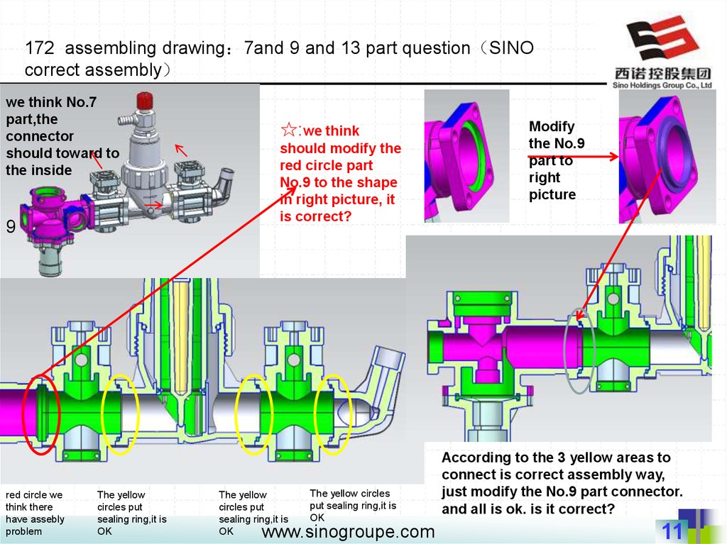
172 assembling drawing 7and 9 and 13 part question SINOcorrect assembly
we think No.7
part,the
connector
should toward to
the inside
9
red circle we
think there
have assebly
problem
The yellow
circles put
sealing ring,it is
OK
☆:we think
should modify the
red circle part
No.9 to the shape
in right picture, it
is correct?
The yellow
circles put
sealing ring,it is
OK
The yellow circles
put sealing ring,it is
OK
www.sinogroupe.com
Modify
the No.9
part to
right
picture
According to the 3 yellow areas to
connect is correct assembly way,
just modify the No.9 part connector.
and all is ok. is it correct?
11
12.
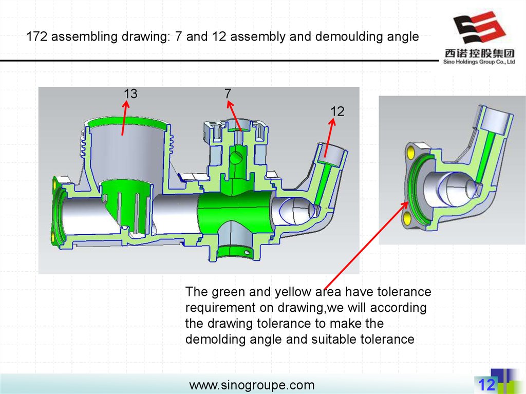
172 assembling drawing: 7 and 12 assembly and demoulding angle13
7
12
The green and yellow area have tolerance
requirement on drawing,we will according
the drawing tolerance to make the
demolding angle and suitable tolerance
www.sinogroupe.com
12
13.
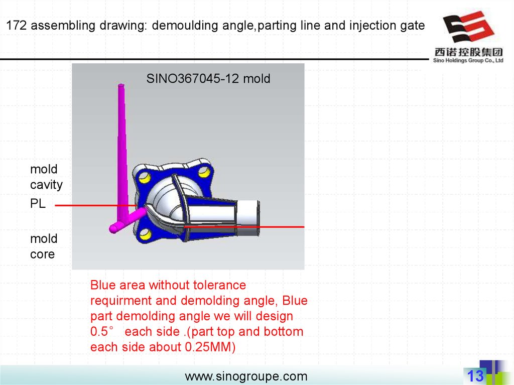
172 assembling drawing: demoulding angle,parting line and injection gateSINO367045-12 mold
mold
cavity
PL
mold
core
Blue area without tolerance
requirment and demolding angle, Blue
part demolding angle we will design
0.5° each side .(part top and bottom
each side about 0.25MM)
www.sinogroupe.com
13
14.
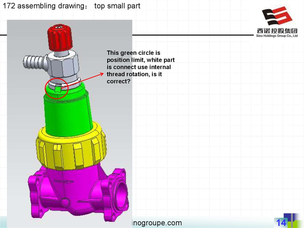
172 assembling drawing top small partThis green circle is
position limit, white part
is connect use internal
thread rotation, is it
correct?
www.sinogroupe.com
14
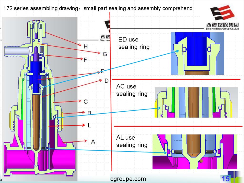
15.
172 series assembling drawing small part sealing and assembly comprehendED use
sealing ring
AC use
sealing ring
L
AL use
sealing ring
www.sinogroupe.com
15
16.
172 series assembling drawing small part sealing and assembly comprehendGF use sealing
ring
GE use sealing
ring
L
CL use sealing
ring
EC use sealing
ring
EF use sealing
ring
www.sinogroupe.com
16
17.
172 series assembling drawing small part sealing and assembly comprehendWhat is the
function of
this conector?
connecting
the gas?
SINO assembly comprehend:
1 / Put 2 sealing rings in L, then put L in A
2 / Put sealing ring in D and E, then put DE in L, small
conical insert A
3 / Put sealing ring in C, then put C in A, B surround
with C, B use Tr72*4 screw to connect with A screw. use
this way, EDL will fixed at ABC inside.
4/
Put 2 sealing rings in G, then F surround with G,F
use G3/4 connect with E.
5/
H use G1/2 screw to fixed with F, then screwing on
it. (IF we adjust the height of the H and screw , G part can
move up and down , is it right? We are not very
understand the function when adjust the part up and
down..Could you tell me?)
L
www.sinogroupe.com
17
18.
172 small product change mold cavityon the contract,we make this two parts in one
mold. but yellow part is slider screw rotation, so
we suggest make green part with No.11 part in
one mold(1+1), make yellow part 2 cavity. do not
need pay money on it.
make this 2 part in
one mold(1+1),
could you accept?
www.sinogroupe.com
18
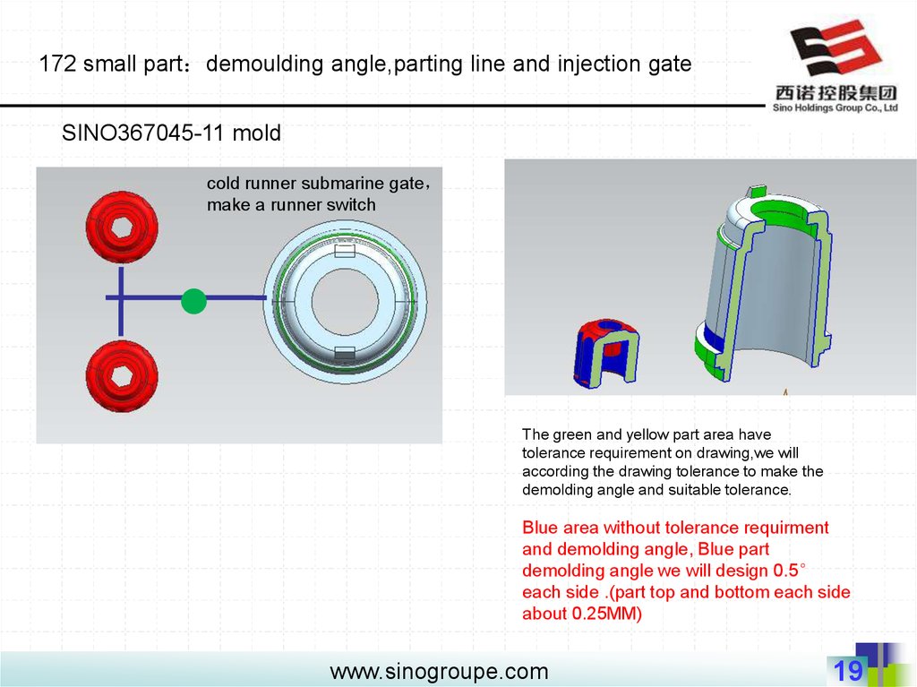
19.
172 small part demoulding angle,parting line and injection gateSINO367045-11 mold
cold runner submarine gate
make a runner switch
The green and yellow part area have
tolerance requirement on drawing,we will
according the drawing tolerance to make the
demolding angle and suitable tolerance.
Blue area without tolerance requirment
and demolding angle, Blue part
demolding angle we will design 0.5°
each side .(part top and bottom each side
about 0.25MM)
www.sinogroupe.com
19
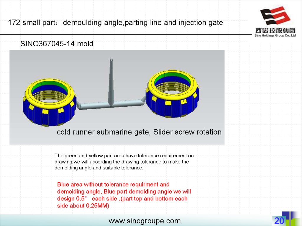
20.
172 small part demoulding angle,parting line and injection gateSINO367045-14 mold
cold runner submarine gate, Slider screw rotation
The green and yellow part area have tolerance requirement on
drawing,we will according the drawing tolerance to make the
demolding angle and suitable tolerance.
Blue area without tolerance requirment and
demolding angle, Blue part demolding angle we will
design 0.5° each side .(part top and bottom each
side about 0.25MM)
www.sinogroupe.com
20
21.
172 small part demoulding angle,parting line and injection gateSINO367045-15 mold
mold
cavity
PL
mold
core
cold runner edge gate,need to
manually cut
Slider screw rotation
The green and yellow part area have
tolerance requirement on drawing,we will
according the drawing tolerance to make
the demolding angle and suitable tolerance.
Blue area without tolerance requirment
and demolding angle, Blue part
demolding angle we will design 0.5°
each side .(part top and bottom each
side about 0.25MM)
www.sinogroupe.com
21
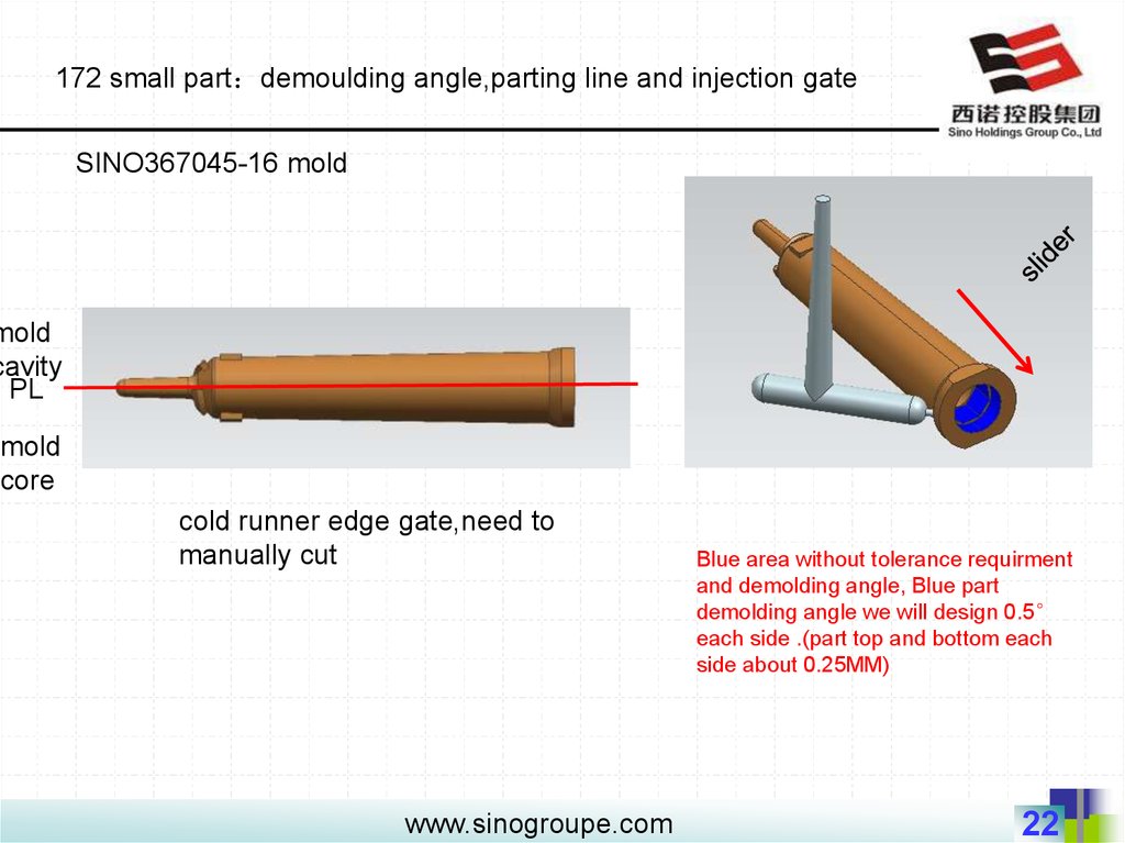
22.
172 small part demoulding angle,parting line and injection gateSINO367045-16 mold
mold
cavity
PL
mold
core
cold runner edge gate,need to
manually cut
www.sinogroupe.com
Blue area without tolerance requirment
and demolding angle, Blue part
demolding angle we will design 0.5°
each side .(part top and bottom each
side about 0.25MM)
22
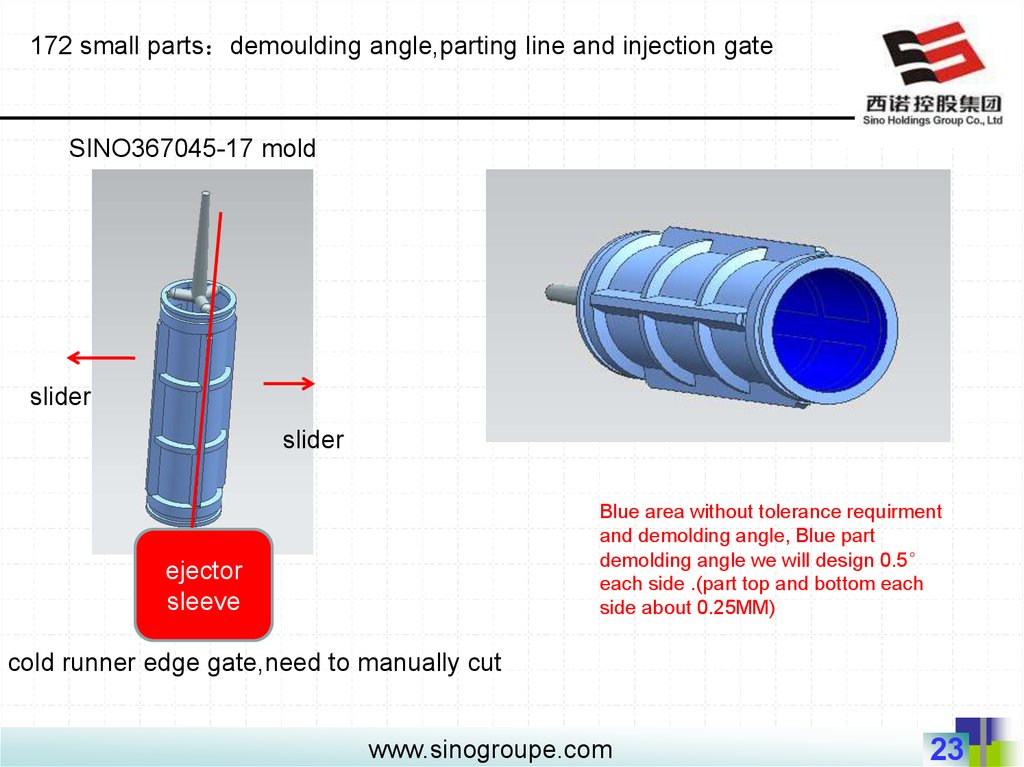
23.
172 small parts demoulding angle,parting line and injection gateSINO367045-17 mold
slider
slider
Blue area without tolerance requirment
and demolding angle, Blue part
demolding angle we will design 0.5°
each side .(part top and bottom each
side about 0.25MM)
ejector
sleeve
cold runner edge gate,need to manually cut
www.sinogroupe.com
23