
 Промышленность
Похожие презентации:


Operation instruction. MK84 series. Automatic CNC roll grinder
1.
OPERATION INSTRUCTIONMK84 SERIES
AUTOMATIC CNC ROLL GRINDER
1
2.
1 SAFETY ALERTSPlease read this instruction carefully and make sure to follow suit, including:
★NOTE: DON’T OPERATE WITHOUT ADEQUTE TRAINING;
★NO STANDING WITHIN 20 METERS OF GRINDING WHEEL ROTATION SURFACE DIRECTION DURING RUNNING;
★DRSS PROPERLY, WEAR GOGGLES, HELMET, WORK SHOES, NO LOOSE CLOTHES AND JELLWERIES;
★DOUBE CHECK EACH TIME ABOUT MAX&MIN DIAMETER, STARTING POINT, ROLL BODY LENTH ETC.;
★DON’T COLLIDE THE ROLL WITH ANY PARTS OF GRINDER DURING LOADING AND UNLOADING;
★WHEN OPERTORING ON MEASURING ARMS, USE 【RESET】 TO BE READY TO STOP THEIR MOVEMENTS
IMMEDIATELY FOR SAFTETY;
7.
Caution slippery floor;
8.
Always be wary of any abnormal phenomenon, sound etc. during running;
9.
Press on the emergency button which can be found in every operation panel in case of emergency to stop the
machine;
10. Please turn the grinder off by key between using; please turn off power before long stop.
★ VILATION OF SATETY ALERTS MAY LEADS TO: A: MACHINE DAMAGE; B: WORK PIECE DAMAGE; C: PERSONEEL
INJURY, EAVE DEATH.
1.
2.
3.
4.
5.
6.
2
3.
2 NOTES BEFORE OPERATION1.
2.
3.
4.
5.
6.
7.
8.
9.
SWITCH BETWEEN CHINESE AND ENGLISH: (1) “MENU”; (2) “SETUP”.
★BEFORE AUTOMATIC GRINDING, IT IS A MUST TO PRESS ON THE “HOMING” BUTTON TO RETURN ALL THE
SERVO AXIS TO REFERENCE POINTS. IF PRESS A SECOND TIME, HEADSTOCK WOULD TURN FOR A SECOND.
Unitary system in this system is “mm”;
Two major packages in the HMI are Hiecise programming(to input roll parameter, curve, and technique) and
Hiecise processing(to grind and measure, manually or automatically).
For better grinding precision, it’s recommended to calibrate the reference disc for measurement after
“Homing”.
For higher precision, it’s advisable to dress the wheel before grinding. For new wheel, do the balance check
again after dressing.
A complete roll file include name, roll data, curve, and grinding technics etc.
A complete automatic grinding process includes measure before grind, roll alignment, wheel automatic
approach, processing and measure after grinding.
Other auxiliary functions includes wheel dressing, chock tilting, headstock faceplate extension, faceplate
automatic alignment, headstock inching, softlanding up & down, tailstock control, online measure.
3
4.
3 PREPARATIONS-WORKINGENVIRONMENT
1.
Remove objects that may impede operation;
2.
Clear the site of irrelevant personnel;
3.
Check liquid level in hydraulic, lubrication and coolant system;
4.
Make sure that all the safety equipment and protection are ready for operation.
4
5.
3 PREPARATIONS-GRINDER STANDBYClear all the problems after checking. Report timely if problems can’t be solved by stuff at site. Don’t
start unless all the problems are cleared. List of checking items are as follows:
1.
Use suitable steady rests and pads (clean pads surface, scrape it if needed to make sure of good fitting
between roll and pad surface);
2.
(Execute u1 homing if there is an U1 axis, see “8 Action Element- U1 Homing”);
3.
Calibrate centerline among headstock, steady rests, tailstock with test roll (by adjusting pads or scraping pads,
see “8 Action Element – Centerline Calibration”);
4.
Check lubrication oil level, including spindle lubrication station, carriage lubrication, pads lubrication, coolant
etc.;
5.
Clean the coolant debris recycle box;
6.
The machine won’t work with electrical cabinet open, please make sure the electrical cabinet is shut.
5
6.
3PREPARATIONS-START
1. Confirm about the status of UPS switch. Start UPS first (UPS switch is on ups device inside
electrical cabinet);
2. Close electrical cabinet and lock it;
3. Turn on the UPS power switch (outside of electrical cabinet, front door);
4. Turn on the main power switch(outside of electrical cabinet, front door);
5. Once power is on, the HMI will start;
6. Be alert to any fault alarms in the HMI;
7. Deal with any fault before proceeding;
8. Press on the “reset” and “fault reset” button;
9. Turn on the machine by rotating the key to “on”;
10. Press on “Homing” button, wait till adjustment finish. U, X1, X, Z axis will return to set reference
points one by one.
11. It is recommended to dry run wheel for 20-30 minutes before grinding for good thermo stability of
machine and smooth lubrication (to empty air completely).
6
7.
4 START & SHUT DOWN AFTER EMERGENCYSTOP
In case of emergency, the grinder can be shut down with pressing on an emergency button,
(time-delay -within 1-30 seconds-is editable), then execute the following steps:
① Turn off the key on the control panel to shut the machine down completely;
② Find out the problem and causes, solve the problem;
③ If restart is needed, rotate the emergency button;
④ Turn on main power switch. ( Caution: turn the main power switch to “off” and turn it to
“on”);
⑤ See “3 Preparation – Start” for the following steps to start.
7
8.
4 START & SHUT DOWN AFTER EMERGENCYSTOP
Firstly, please shut down the grinder completely through the key on control panel.
The main power swith will be between【off】 and【on】.
If need to start system right away (if power supply become stable again), then please
swith the main power switch firstly to 【off】 than to 【on】.
Follow the steps in “ 3 Preparation – Start ”.
If the system needs to be shut down for a long time, switch the main power switch to
【off】, and then turn off UPS power supply and UPS itself step by step.
8
9.
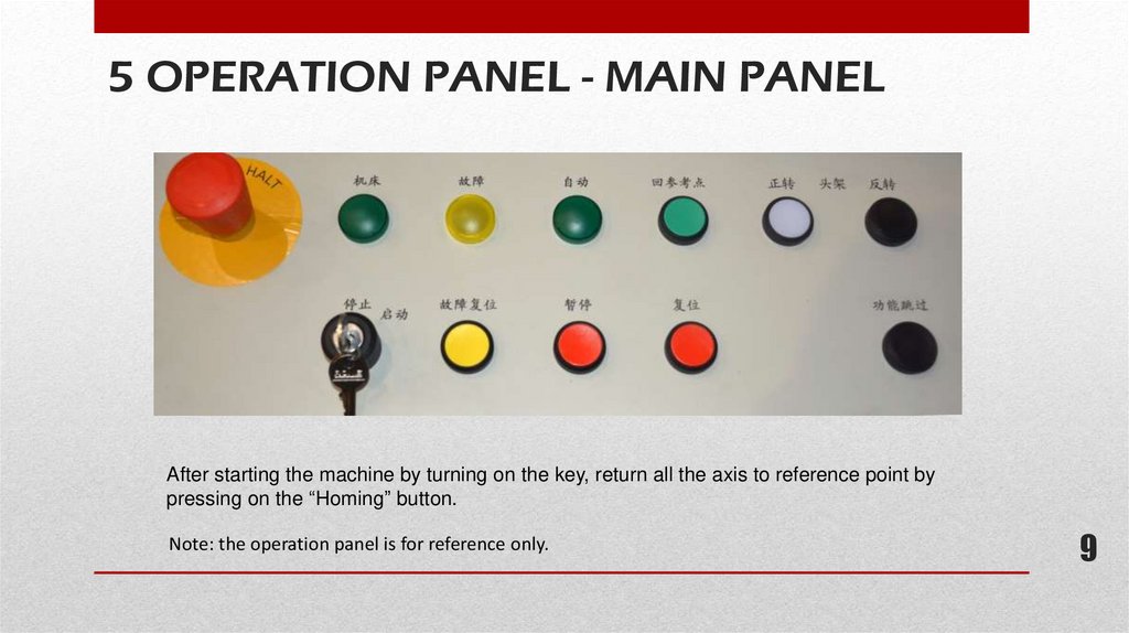
5 OPERATION PANEL - MAIN PANELAfter starting the machine by turning on the key, return all the axis to reference point by
pressing on the “Homing” button.
Note: the operation panel is for reference only.
9
10.
·【Emergency stop】: press in case of emergency, rotate to reset;·【Start/stop】: key to start and stop the machine;
·【On】: machine is on (green);
·【Fault reset】: fault reset, to clear PLC fault alarm display;
·【Fault】: light is on for slight fault; light flashes for serious faults;
·【Halt】: stop the carriage movement in manual operation;
·【Automatic】: automatic running (green);
·【Reset】: NC reset, press it for the following actions:
1. All the actions stop except for the lubrication pump and ventilator(★ ★ this can be used to stop at any time the
movement of measuring arms to protect them form damaging);
2. Automatic procedure stops;
3. All the NC fault display will be cleared (reset).
·【Homing】: return all the servo axis to their reference points.
·【Function skip】: also called【function trigger】, with the same function as the middle button on the hand held control
box. With functions as follows:
1. Change the direction of the carriage movement;
2. End ahead of time the automatic approach of grinding wheel in automatic mode;
3. End the carriage movement to tailstock after automatic cycling;
4. Triger the automatic grinding when approaching the grinding wheel to rolll manually.
10
11.
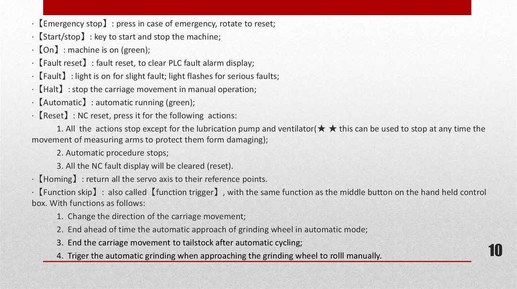
Explanation:1.
2.
3.
4.
5.
6.
7.
Faceplate clockwise
inching.
Faceplate counterclockwise inching.
Faceplate extension
inching.
Faceplate retraction
inching.
Softlanding up.
Softlanding down.
Emergency stop.
Note: Illustration shown on the
right is of standard configuration.
11
5 OPERATION PANEL - HEADSTOCK
12.
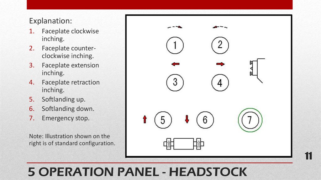
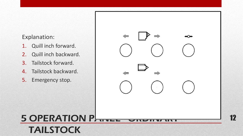
Explanation:1.
2.
3.
4.
5.
Quill inch forward.
Quill inch backward.
Tailstock forward.
Tailstock backward.
Emergency stop.
5 OPERATION PANEL - ORDINARY
TAILSTOCK
12
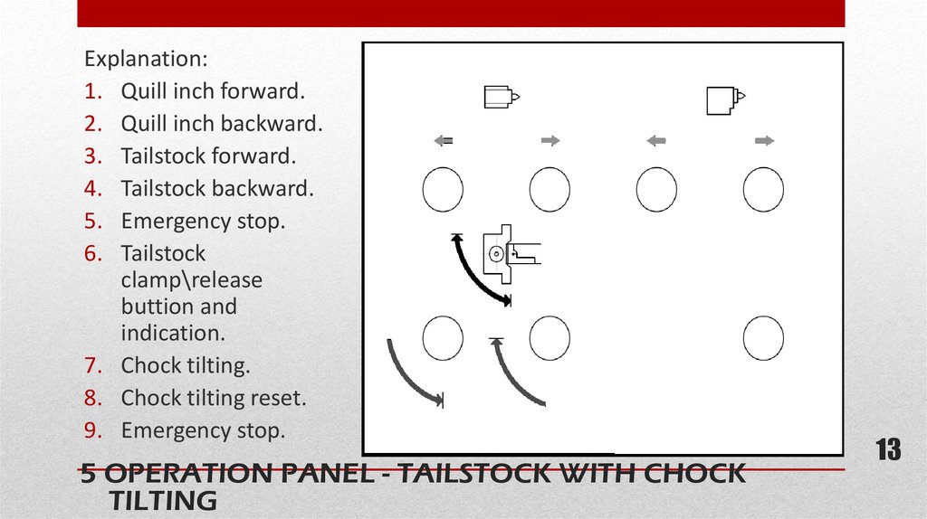
13.
Explanation:1. Quill inch forward.
2. Quill inch backward.
3. Tailstock forward.
4. Tailstock backward.
5. Emergency stop.
6. Tailstock
clamp\release
buttion and
indication.
7. Chock tilting.
8. Chock tilting reset.
9. Emergency stop.
5 OPERATION PANEL - TAILSTOCK WITH CHOCK
TILTING
13
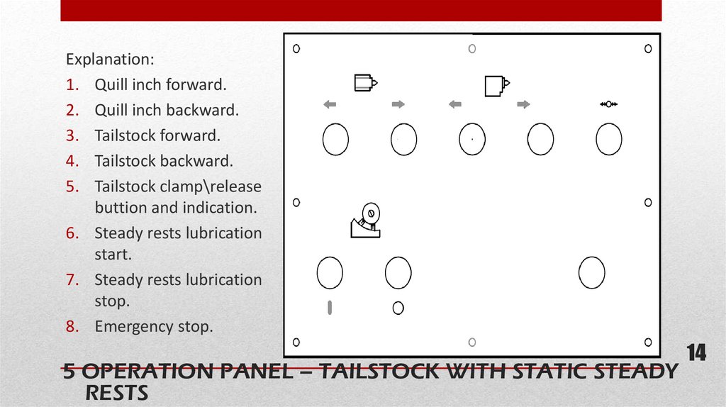
14.
Explanation:1. Quill inch forward.
2. Quill inch backward.
3. Tailstock forward.
4. Tailstock backward.
5. Tailstock clamp\release
buttion and indication.
6. Steady rests lubrication
start.
7. Steady rests lubrication
stop.
8. Emergency stop.
5 OPERATION PANEL – TAILSTOCK WITH STATIC STEADY
RESTS
14
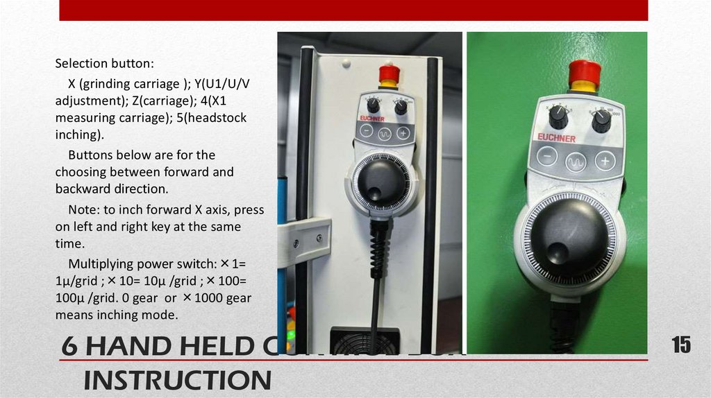
15.
Selection button:X (grinding carriage ); Y(U1/U/V
adjustment); Z(carriage); 4(X1
measuring carriage); 5(headstock
inching).
Buttons below are for the
choosing between forward and
backward direction.
Note: to inch forward X axis, press
on left and right key at the same
time.
Multiplying power switch:×1=
1μ/grid ;×10= 10μ /grid ;×100=
100μ /grid. 0 gear or ×1000 gear
means inching mode.
6 HAND HELD CONTROL BOX
INSTRUCTION
15
15
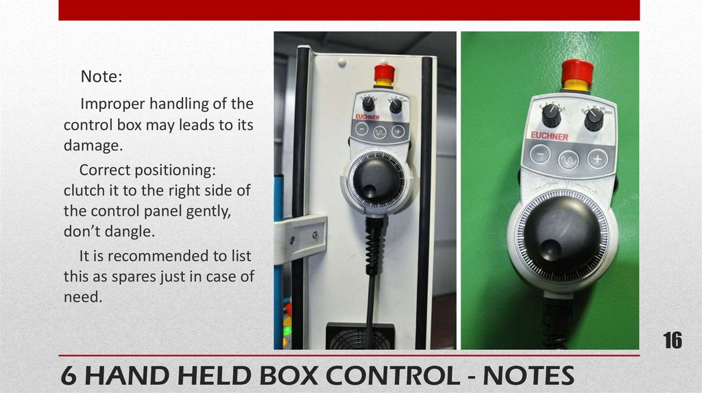
16.
Note:Improper handling of the
control box may leads to its
damage.
Correct positioning:
clutch it to the right side of
the control panel gently,
don’t dangle.
It is recommended to list
this as spares just in case of
need.
16
6 HAND HELD BOX CONTROL - NOTES
16
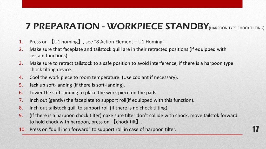
17.
7 PREPARATION - WORKPIECE STANDBY(HARPOON TYPE CHOCK TILTING)Press on 【U1 homing】, see “8 Action Element – U1 Homing”.
Make sure that faceplate and tailstock quill are in their retracted positions (if equipped with
certain functions).
3. Make sure to retract tailstock to a safe position to avoid interference, if there is a harpoon type
chock tilting device.
4. Cool the work piece to room temperature. (Use coolant if necessary).
5. Jack up soft-landing (if there is soft-landing).
6. Lower the soft-landing to place the work piece on the pads.
7. Inch out (gently) the faceplate to support roll(if equipped with this function).
8. Inch out tailstock quill to support roll (if there is no chock tilting).
9. (If there is a harpoon chock tilter)make sure tilter don’t collide with chock, move tailstok forward
to hold chock with harpoon, press on 【chock tilt】.
10. Press on “quill inch forward” to support roll in case of harpoon tilter.
1.
2.
17
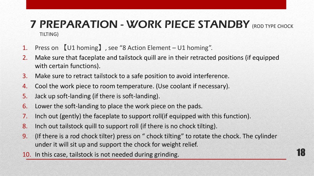
18.
7 PREPARATION - WORK PIECE STANDBY (ROD TYPE CHOCKTILTING)
Press on 【U1 homing】, see “8 Action Element – U1 homing”.
Make sure that faceplate and tailstock quill are in their retracted positions (if equipped
with certain functions).
3. Make sure to retract tailstock to a safe position to avoid interference.
4. Cool the work piece to room temperature. (Use coolant if necessary).
5. Jack up soft-landing (if there is soft-landing).
6. Lower the soft-landing to place the work piece on the pads.
7. Inch out (gently) the faceplate to support roll(if equipped with this function).
8. Inch out tailstock quill to support roll (if there is no chock tilting).
9. (If there is a rod chock tilter) press on “ chock tilting” to rotate the chock. The cylinder
under it will sit up and support the chock for weight relief.
10. In this case, tailstock is not needed during grinding.
1.
2.
18
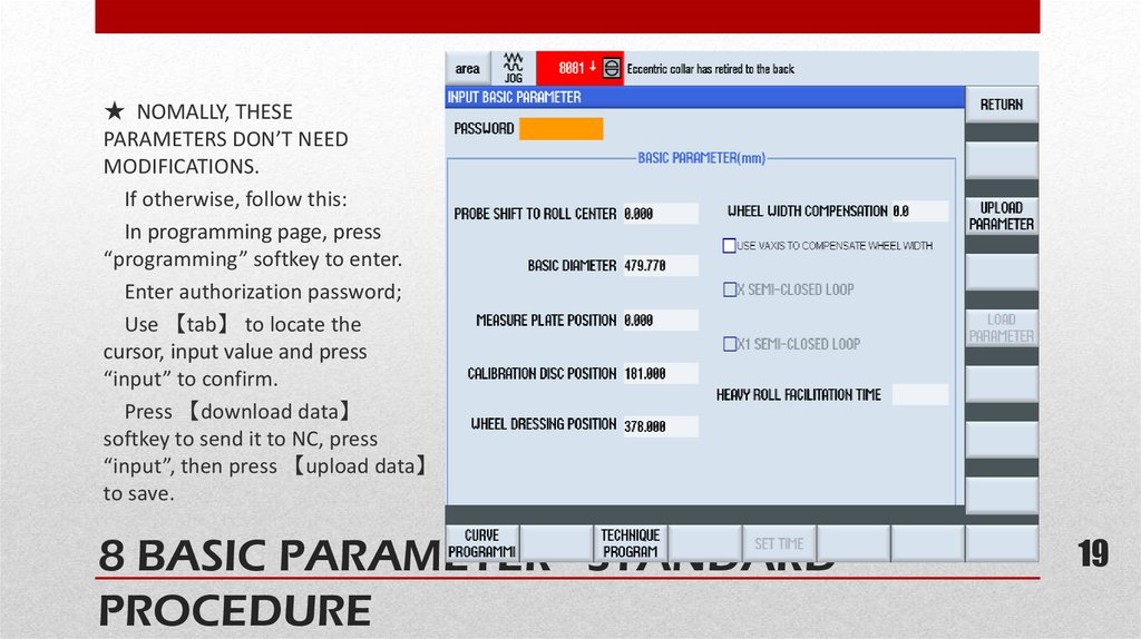
19.
★ NOMALLY, THESEPARAMETERS DON’T NEED
MODIFICATIONS.
If otherwise, follow this:
In programming page, press
“programming” softkey to enter.
Enter authorization password;
Use 【tab】 to locate the
cursor, input value and press
“input” to confirm.
Press 【download data】
softkey to send it to NC, press
“input”, then press 【upload data】
to save.
8 BASIC PARAMETER - STANDARD
PROCEDURE
19
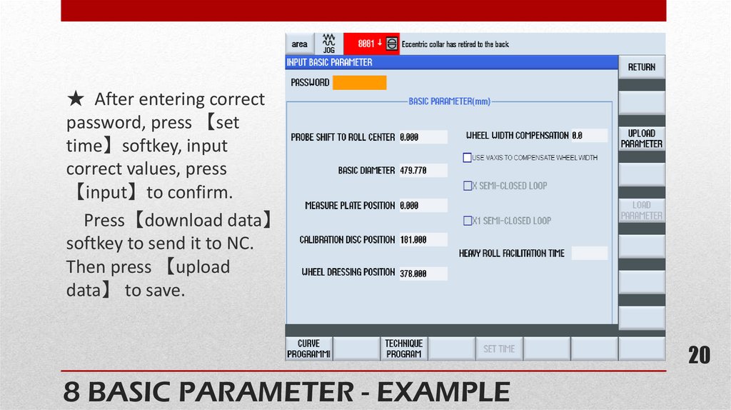
20.
★ After entering correctpassword, press 【set
time】softkey, input
correct values, press
【input】to confirm.
Press【download data】
softkey to send it to NC.
Then press 【upload
data】 to save.
20
8 BASIC PARAMETER - EXAMPLE
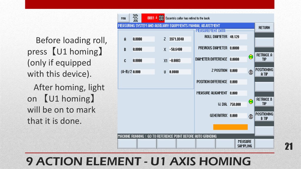
21.
Before loading roll,press【U1 homing】
(only if equipped
with this device).
After homing, light
on 【U1 homing】
will be on to mark
that it is done.
21
9 ACTION ELEMENT - U1 AXIS HOMING
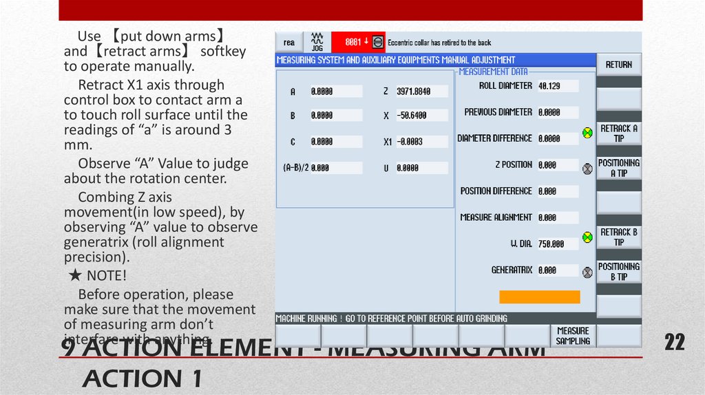
22.
Use 【put down arms】and【retract arms】 softkey
to operate manually.
Retract X1 axis through
control box to contact arm a
to touch roll surface until the
readings of “a” is around 3
mm.
Observe “A” Value to judge
about the rotation center.
Combing Z axis
movement(in low speed), by
observing “A” value to observe
generatrix (roll alignment
precision).
★ NOTE!
Before operation, please
make sure that the movement
of measuring arm don’t
interfare with anything.
9 ACTION ELEMENT - MEASURING ARM
ACTION 1
22
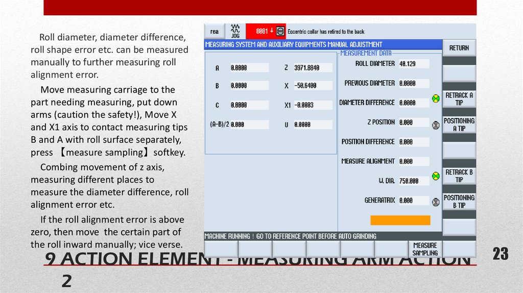
23.
Roll diameter, diameter difference,roll shape error etc. can be measured
manually to further measuring roll
alignment error.
Move measuring carriage to the
part needing measuring, put down
arms (caution the safety!), Move X
and X1 axis to contact measuring tips
B and A with roll surface separately,
press 【measure sampling】softkey.
Combing movement of z axis,
measuring different places to
measure the diameter difference, roll
alignment error etc.
If the roll alignment error is above
zero, then move the certain part of
the roll inward manually; vice verse.
9 ACTION ELEMENT - MEASURING ARM ACTION
2
23
24.
PREPARATIONS - GRINDER STANDBY CENTERLINE① Measure the generatrix of roll to get a general idea on roll alignment(cross-sectional and vertical);
② Place a dial gauge near headstock side’s roll neck to measure the rotation center;
③ Adjust rotation center through pads based on measuring result;
④ Place a dial gauge near tailstock side’s roll neck to further measure rotation center;
⑤ Repeat the measuring on headstock and tailstock side to calibrate center;
⑥ Measuring arms can also be used to measuring the rotation center;
⑦ Adjust roll generatrix with help of measuring system;
⑧ Repeat measurement with centimeter to adjust roll upper centerlines, generatrix to calibrate
rotation centerline of headstock, tailstock, steady rests.
24
25.
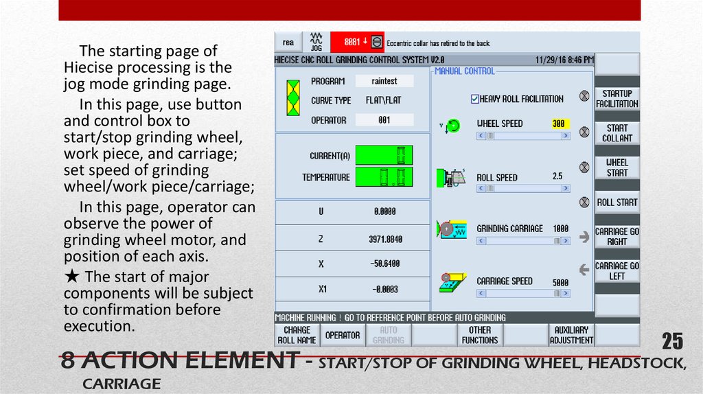
The starting page ofHiecise processing is the
jog mode grinding page.
In this page, use button
and control box to
start/stop grinding wheel,
work piece, and carriage;
set speed of grinding
wheel/work piece/carriage;
In this page, operator can
observe the power of
grinding wheel motor, and
position of each axis.
★ The start of major
components will be subject
to confirmation before
execution.
25
25
8 ACTION ELEMENT - START/STOP OF GRINDING WHEEL, HEADSTOCK,
CARRIAGE
26.
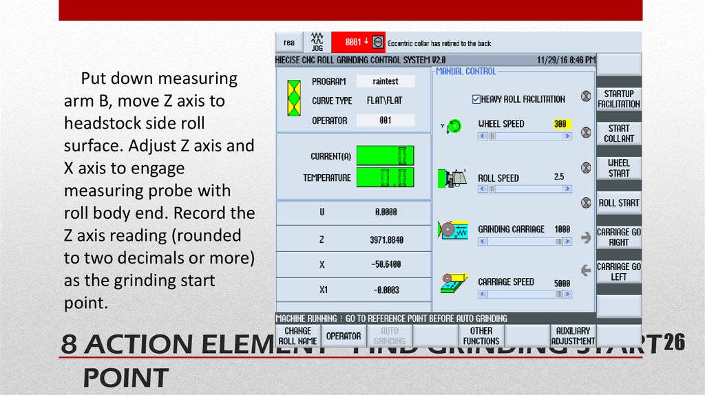
Put down measuringarm B, move Z axis to
headstock side roll
surface. Adjust Z axis and
X axis to engage
measuring probe with
roll body end. Record the
Z axis reading (rounded
to two decimals or more)
as the grinding start
point.
26 26
8 ACTION ELEMENT - FIND GRINDING START
POINT
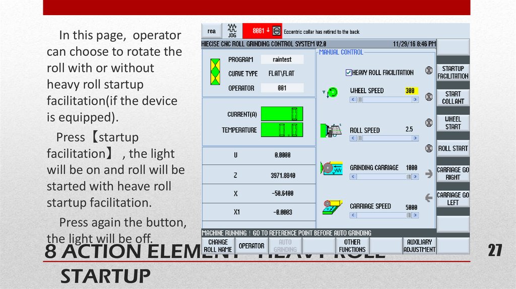
27.
In this page, operatorcan choose to rotate the
roll with or without
heavy roll startup
facilitation(if the device
is equipped).
Press【startup
facilitation】 , the light
will be on and roll will be
started with heave roll
startup facilitation.
Press again the button,
the light will be off.
8 ACTION ELEMENT - HEAVY ROLL
STARTUP
27
27
28.
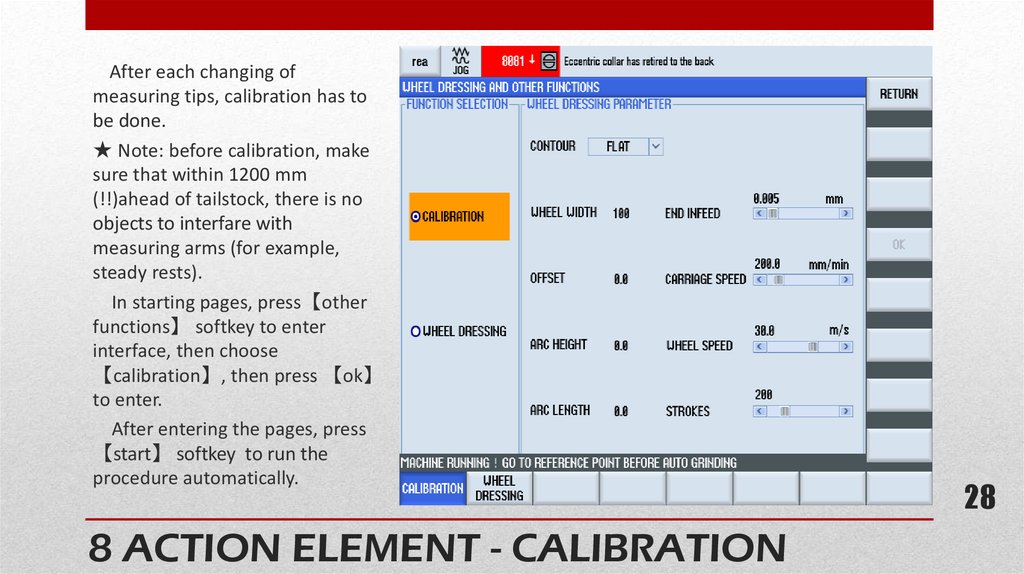
After each changing ofmeasuring tips, calibration has to
be done.
★ Note: before calibration, make
sure that within 1200 mm
(!!)ahead of tailstock, there is no
objects to interfare with
measuring arms (for example,
steady rests).
In starting pages, press【other
functions】 softkey to enter
interface, then choose
【calibration】, then press 【ok】
to enter.
After entering the pages, press
【start】 softkey to run the
procedure automatically.
8 ACTION ELEMENT - CALIBRATION
28
28
29.
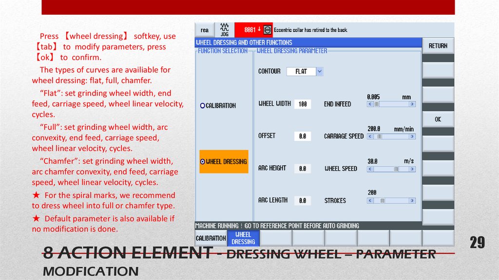
Press 【wheel dressing】 softkey, use【tab】 to modify parameters, press
【ok】 to confirm.
The types of curves are availiable for
wheel dressing: flat, full, chamfer.
“Flat”: set grinding wheel width, end
feed, carriage speed, wheel linear velocity,
cycles.
“Full”: set grinding wheel width, arc
convexity, end feed, carriage speed,
wheel linear velocity, cycles.
“Chamfer”: set grinding wheel width,
arc chamfer convexity, end feed, carriage
speed, wheel linear velocity, cycles.
★ For the spiral marks, we recommend
to dress wheel into full or chamfer type.
★ Default parameter is also available if
no modification is done.
8 ACTION ELEMENT - DRESSING WHEEL – PARAMETER
MODFICATION
29
29
30.
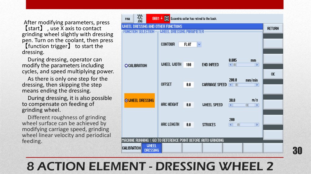
After modifying parameters, press【start】 , use X axis to contact
grinding wheel slightly with dressing
pen. Turn on the coolant, then press
【function trigger】 to start the
dressing.
During dressing, operator can
modify the parameters including
cycles, and speed multiplying power.
As there is only one step for the
dressing, then skipping the step
means ending the dressing.
During dressing, it is also possible
to compensate on feeding of
grinding wheel.
Different roughness of grinding
wheel surface can be achieved by
modifying carriage speed, grinding
wheel linear velocity and periodical
feeding.
30
8 ACTION ELEMENT - DRESSING WHEEL 2
30
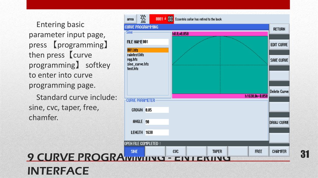
31.
Entering basicparameter input page,
press 【programming】
then press【curve
programming】 softkey
to enter into curve
programming page.
Standard curve include:
sine, cvc, taper, free,
chamfer.
9 CURVE PROGRAMMING - ENTERING
INTERFACE
31
31
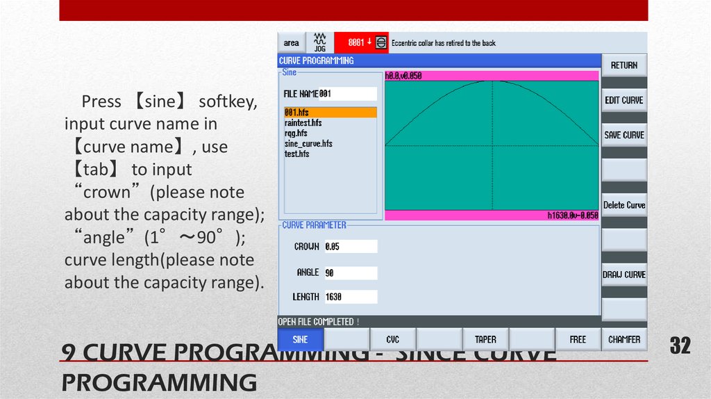
32.
Press 【sine】 softkey,input curve name in
【curve name】, use
【tab】 to input
“crown”(please note
about the capacity range);
“angle”(1° 90°);
curve length(please note
about the capacity range).
9 CURVE PROGRAMMING - SINCE CURVE
PROGRAMMING
32
32
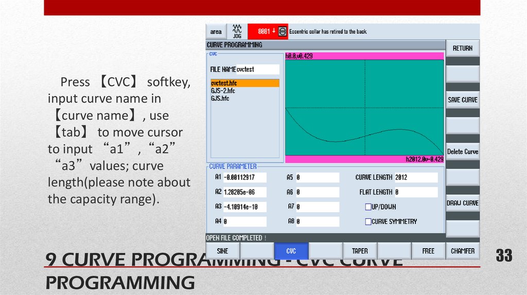
33.
Press 【CVC】 softkey,input curve name in
【curve name】, use
【tab】 to move cursor
to input “a1”,“a2”
“a3”values; curve
length(please note about
the capacity range).
9 CURVE PROGRAMMING - CVC CURVE
PROGRAMMING
33
33
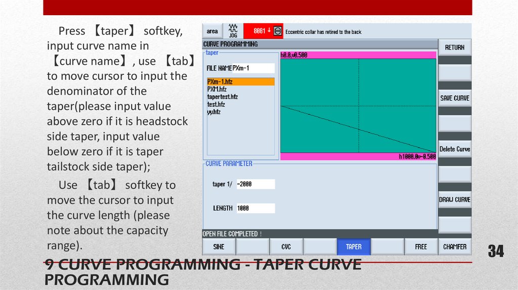
34.
Press 【taper】 softkey,input curve name in
【curve name】, use 【tab】
to move cursor to input the
denominator of the
taper(please input value
above zero if it is headstock
side taper, input value
below zero if it is taper
tailstock side taper);
Use 【tab】 softkey to
move the cursor to input
the curve length (please
note about the capacity
range).
9 CURVE PROGRAMMING - TAPER CURVE
PROGRAMMING
34
34
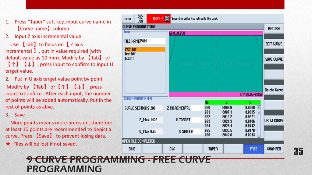
35.
1. Press “Taper” soft key, input curve name in【Curve name】column.
2. Input Z axis incremental value
Use 【Tab】to focus on【 Z axis
incremental 】, put in value required (with
default value as 10 mm). Modify by 【Tab】 or
【↑】【↓】, press input to confirm to input U
target value.
2. Put in U axis target value point by point
Modify by 【Tab】 or【↑】【↓】, press
input to confirm . After each input, the number
of points will be added automatically. Put in the
rest of points as abve.
3. Save
More points means more precision, therefore
at least 10 points are recommended to depict a
curve. Press 【Save】 to prevent losing data.
★ Files will be lost if not saved.
9 CURVE PROGRAMMING - FREE CURVE
PROGRAMMING
35
35
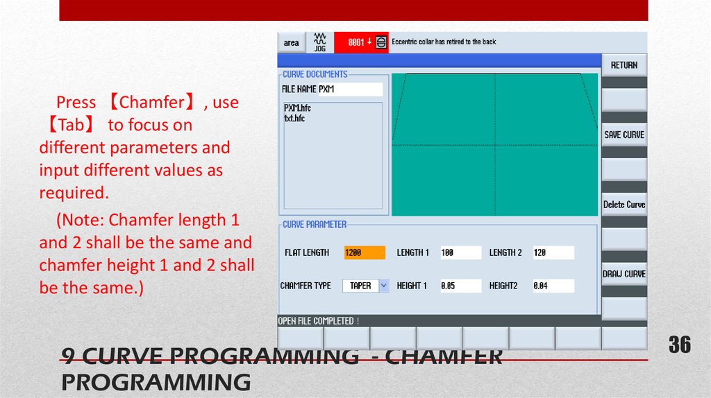
36.
Press 【Chamfer】, use【Tab】 to focus on
different parameters and
input different values as
required.
(Note: Chamfer length 1
and 2 shall be the same and
chamfer height 1 and 2 shall
be the same.)
9 CURVE PROGRAMMING - CHAMFER
PROGRAMMING
36
36
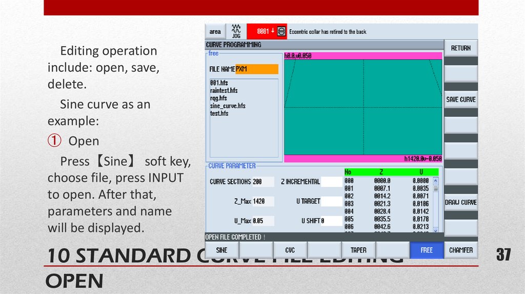
37.
Editing operationinclude: open, save,
delete.
Sine curve as an
example:
① Open
Press【Sine】 soft key,
choose file, press INPUT
to open. After that,
parameters and name
will be displayed.
10 STANDARD CURVE FILE EDITING OPEN
37
37
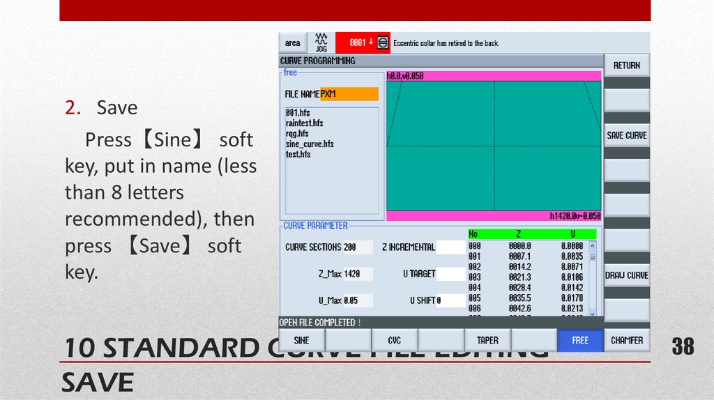
38.
2. SavePress【Sine】 soft
key, put in name (less
than 8 letters
recommended), then
press 【Save】 soft
key.
10 STANDARD CURVE FILE EDITING SAVE
38
38
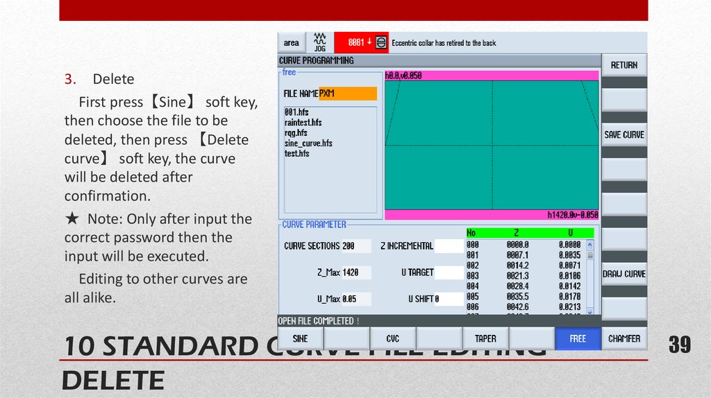
39.
3.Delete
First press【Sine】 soft key,
then choose the file to be
deleted, then press 【Delete
curve】 soft key, the curve
will be deleted after
confirmation.
★ Note: Only after input the
correct password then the
input will be executed.
Editing to other curves are
all alike.
10 STANDARD CURVE FILE EDITING DELETE
39
39
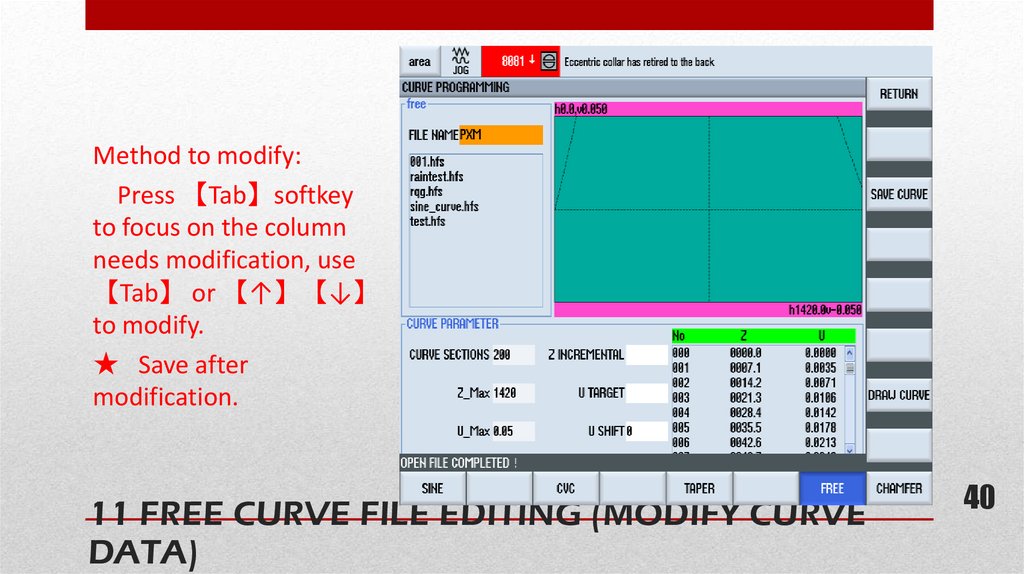
40.
Method to modify:Press 【Tab】softkey
to focus on the column
needs modification, use
【Tab】 or 【↑】【↓】
to modify.
★ Save after
modification.
11 FREE CURVE FILE EDITING (MODIFY CURVE
DATA)
40
40
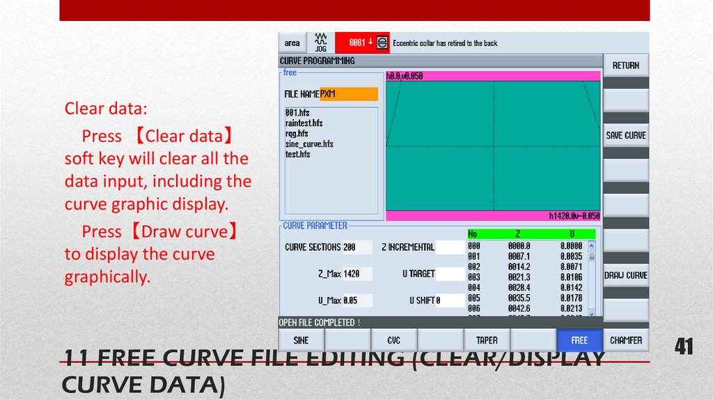
41.
Clear data:Press 【Clear data】
soft key will clear all the
data input, including the
curve graphic display.
Press【Draw curve】
to display the curve
graphically.
11 FREE CURVE FILE EDITING (CLEAR/DISPLAY
CURVE DATA)
41
41
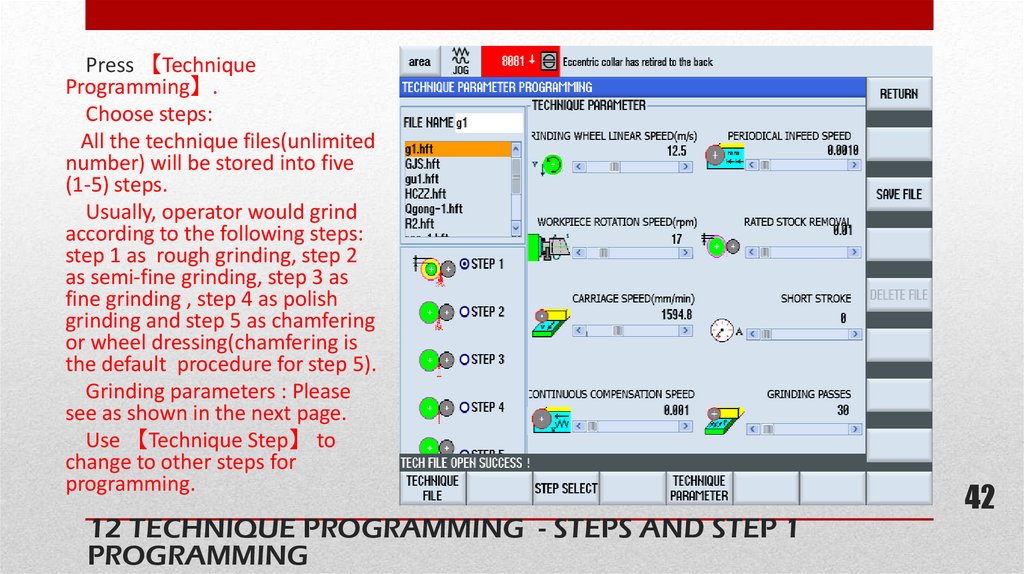
42.
Press 【TechniqueProgramming】.
Choose steps:
All the technique files(unlimited
number) will be stored into five
(1-5) steps.
Usually, operator would grind
according to the following steps:
step 1 as rough grinding, step 2
as semi-fine grinding, step 3 as
fine grinding , step 4 as polish
grinding and step 5 as chamfering
or wheel dressing(chamfering is
the default procedure for step 5).
Grinding parameters : Please
see as shown in the next page.
Use 【Technique Step】 to
change to other steps for
programming.
12 TECHNIQUE PROGRAMMING - STEPS AND STEP 1
PROGRAMMING
42
42
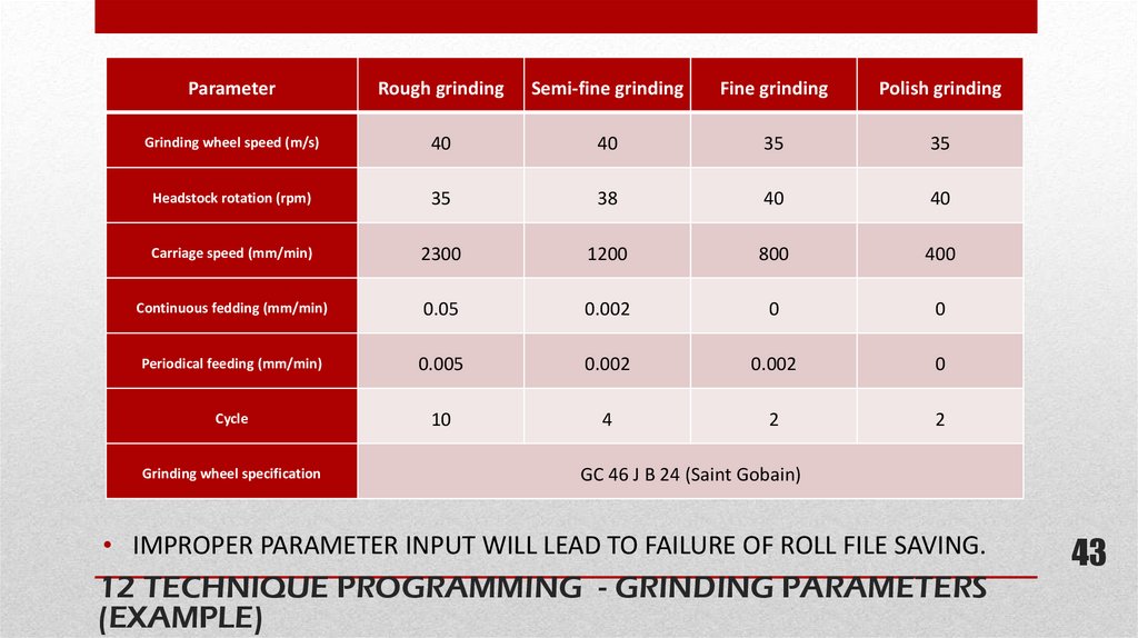
43.
ParameterRough grinding
Semi-fine grinding
Fine grinding
Polish grinding
Grinding wheel speed (m/s)
40
40
35
35
Headstock rotation (rpm)
35
38
40
40
Carriage speed (mm/min)
2300
1200
800
400
Continuous fedding (mm/min)
0.05
0.002
0
0
Periodical feeding (mm/min)
0.005
0.002
0.002
0
Cycle
10
4
2
2
Grinding wheel specification
GC 46 J B 24 (Saint Gobain)
• IMPROPER PARAMETER INPUT WILL LEAD TO FAILURE OF ROLL FILE SAVING.
12 TECHNIQUE PROGRAMMING - GRINDING PARAMETERS
(EXAMPLE)
43
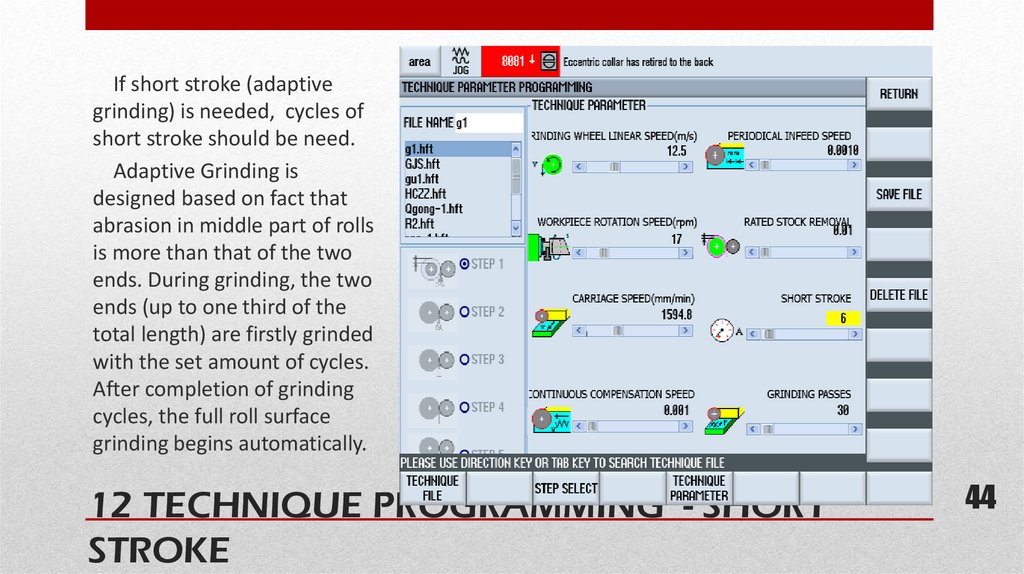
44.
If short stroke (adaptivegrinding) is needed, cycles of
short stroke should be need.
Adaptive Grinding is
designed based on fact that
abrasion in middle part of rolls
is more than that of the two
ends. During grinding, the two
ends (up to one third of the
total length) are firstly grinded
with the set amount of cycles.
After completion of grinding
cycles, the full roll surface
grinding begins automatically.
12 TECHNIQUE PROGRAMMING - SHORT
STROKE
44
44
45.
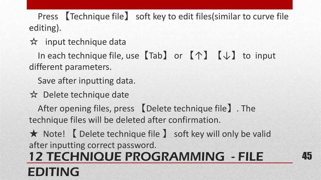
Press 【Technique file】 soft key to edit files(similar to curve fileediting).
☆ input technique data
In each technique file, use【Tab】 or 【↑】【↓】 to input
different parameters.
Save after inputting data.
☆ Delete technique date
After opening files, press 【Delete technique file】. The
technique files will be deleted after confirmation.
★ Note! 【 Delete technique file 】 soft key will only be valid
after inputting correct password.
12 TECHNIQUE PROGRAMMING - FILE
EDITING
45
46.
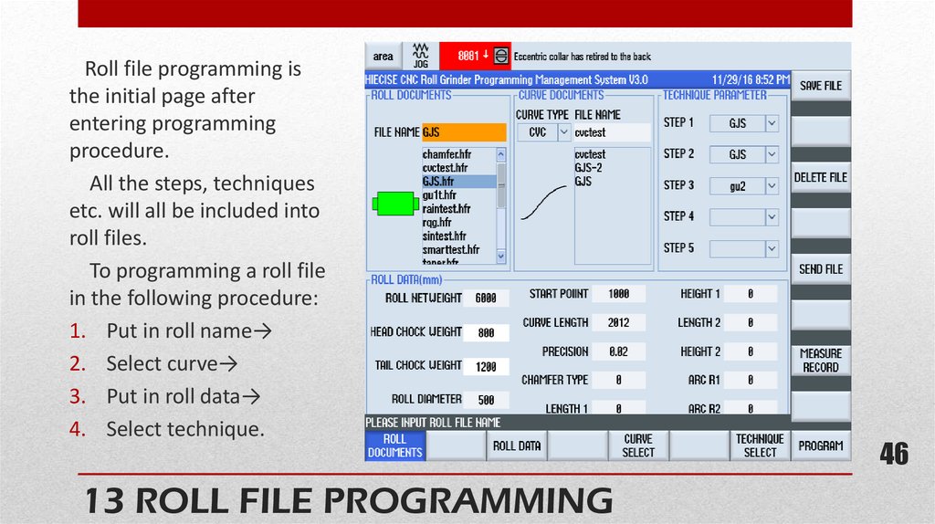
Roll file programming isthe initial page after
entering programming
procedure.
All the steps, techniques
etc. will all be included into
roll files.
To programming a roll file
in the following procedure:
1. Put in roll name→
2. Select curve→
3. Put in roll data→
4. Select technique.
13 ROLL FILE PROGRAMMING
46
46
47.
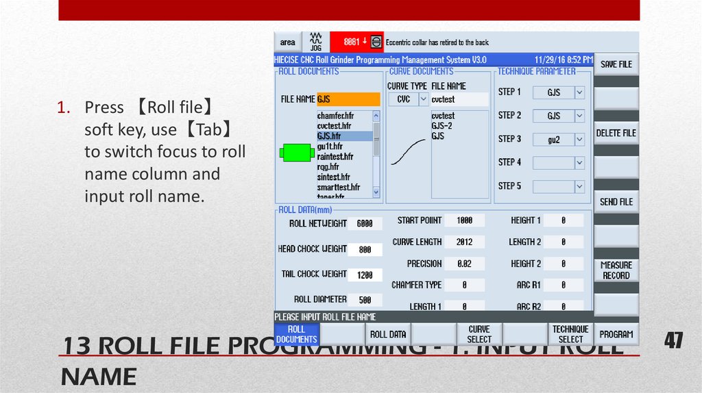
1. Press 【Roll file】soft key, use【Tab】
to switch focus to roll
name column and
input roll name.
13 ROLL FILE PROGRAMMING - 1. INPUT ROLL47
NAME
47
48.
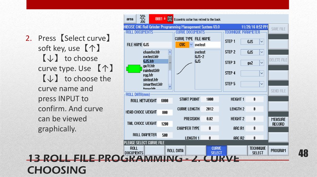
2. Press【Select curve】soft key, use【↑】
【↓】 to choose
curve type. Use 【↑】
【↓】 to choose the
curve name and
press INPUT to
confirm. And curve
can be viewed
graphically.
13 ROLL FILE PROGRAMMING - 2. CURVE
CHOOSING
48
48
49.
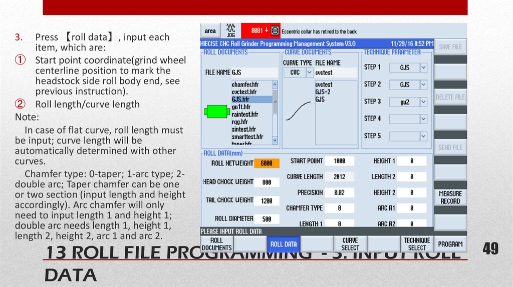
Press 【roll data】, input eachitem, which are:
① Start point coordinate(grind wheel
centerline position to mark the
headstock side roll body end, see
previous instruction).
② Roll length/curve length
Note:
In case of flat curve, roll length must
be input; curve length will be
automatically determined with other
curves.
Chamfer type: 0-taper; 1-arc type; 2double arc; Taper chamfer can be one
or two section (input length and height
accordingly). Arc chamfer will only
need to input length 1 and height 1;
double arc needs length 1, height 1,
length 2, height 2, arc 1 and arc 2.
3.
49 49
13 ROLL FILE PROGRAMMING - 3. INPUT ROLL
DATA
50.
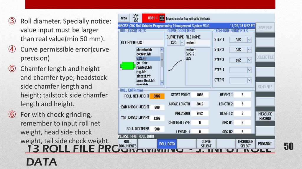
③ Roll diameter. Specially notice:value input must be larger
than real value(min 50 mm).
④ Curve permissible error(curve
precision)
⑤ Chamfer length and height
and chamfer type; headstock
side chamfer length and
height; tailstock side chamfer
length and height.
⑥ For with chock grinding,
remember to input roll net
weight, head side chock
weight, tail side chock weight.
50 50
13 ROLL FILE PROGRAMMING - 3. INPUT ROLL
DATA
51.
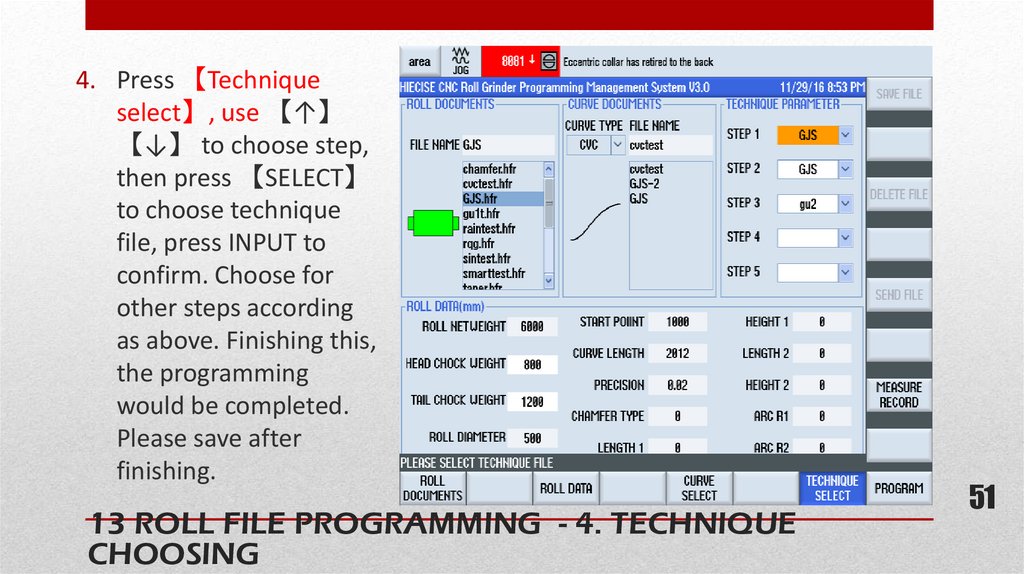
4. Press 【Techniqueselect】, use 【↑】
【↓】 to choose step,
then press 【SELECT】
to choose technique
file, press INPUT to
confirm. Choose for
other steps according
as above. Finishing this,
the programming
would be completed.
Please save after
finishing.
13 ROLL FILE PROGRAMMING - 4. TECHNIQUE
CHOOSING
51
51
52.
☆ Save roll: Press 【Save roll】 and confirm.☆ Open roll program (file):
Press 【Roll file】, choose and open by INPUT.
☆ Delete roll programming:
Press 【Roll file】, choose and delete after confirmation.
★ Note! 【 Delete roll】 soft key will only be valid after inputting correct password.
☆ load(transfer) roll program
Before grinding, roll program should be transferred.
First, press 【Roll file】, choose and open file, and press【Send file】 and confirm.
For the next grinding, if the roll is the same, Sending is not needed again.
☆ Back to main interface, press the button “Operator” to input or change operator,
press【INPUT】 to confirm, press 【Auto grinding】 to enter into automatic grinding
interface.
13 ROLL FILE PROGRAMMING - ROLL FILE
PROGRAMMING
52
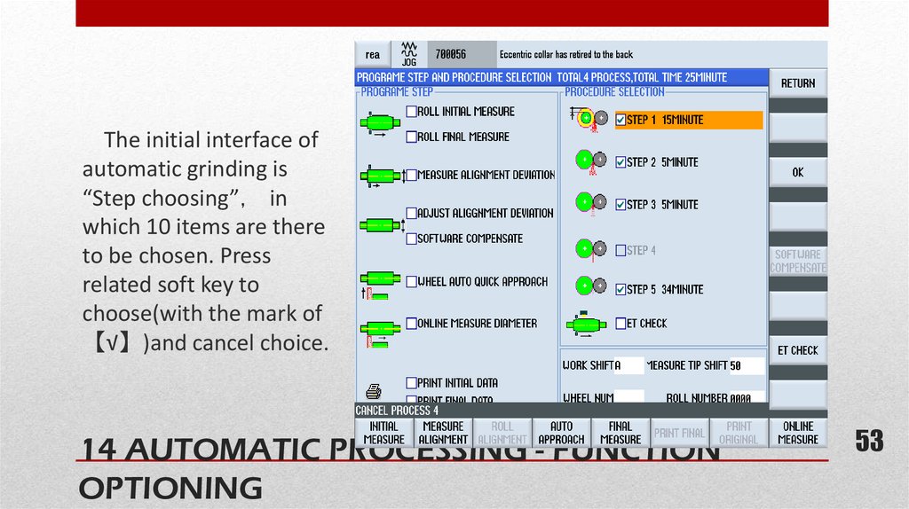
53.
The initial interface ofautomatic grinding is
“Step choosing” in
which 10 items are there
to be chosen. Press
related soft key to
choose(with the mark of
【√】)and cancel choice.
14 AUTOMATIC PROCESSING - FUNCTION
OPTIONING
53
53
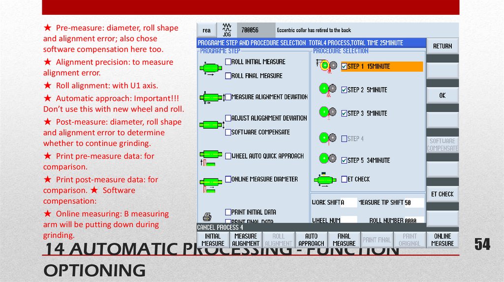
54.
★ Pre-measure: diameter, roll shapeand alignment error; also chose
software compensation here too.
★ Alignment precision: to measure
alignment error.
★ Roll alignment: with U1 axis.
★ Automatic approach: Important!!!
Don’t use this with new wheel and roll.
★ Post-measure: diameter, roll shape
and alignment error to determine
whether to continue grinding.
★ Print pre-measure data: for
comparison.
★ Print post-measure data: for
comparison. ★ Software
compensation:
★ Online measuring: B measuring
arm will be putting down during
grinding.
14 AUTOMATIC PROCESSING - FUNCTION
OPTIONING
54
54
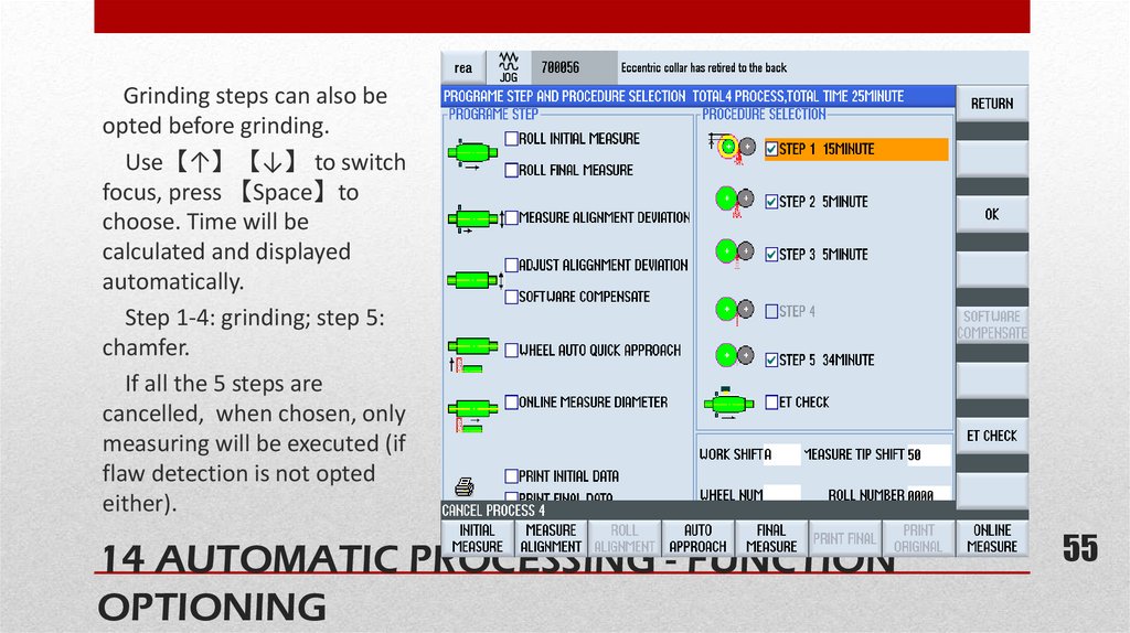
55.
Grinding steps can also beopted before grinding.
Use【↑】【↓】 to switch
focus, press 【Space】to
choose. Time will be
calculated and displayed
automatically.
Step 1-4: grinding; step 5:
chamfer.
If all the 5 steps are
cancelled, when chosen, only
measuring will be executed (if
flaw detection is not opted
either).
14 AUTOMATIC PROCESSING - FUNCTION
OPTIONING
55
55
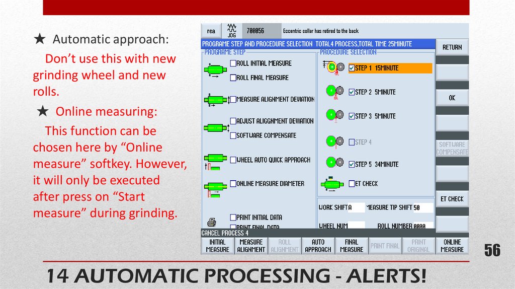
56.
★ Automatic approach:Don’t use this with new
grinding wheel and new
rolls.
★ Online measuring:
This function can be
chosen here by “Online
measure” softkey. However,
it will only be executed
after press on “Start
measure” during grinding.
56
14 AUTOMATIC PROCESSING - ALERTS!
56
57.
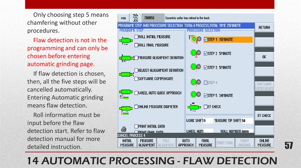
Only choosing step 5 meanschamfering without other
procedures.
Flaw detection is not in the
programming and can only be
chosen before entering
automatic grinding page.
If flaw detection is chosen,
then, all the five steps will be
cancelled automatically.
Entering Automatic grinding
means flaw detection.
Roll information must be
input before the flaw
detection start. Refer to flaw
detection manual for more
detailed instruction.
57
14 AUTOMATIC PROCESSING - FLAW DETECTION
57
58.
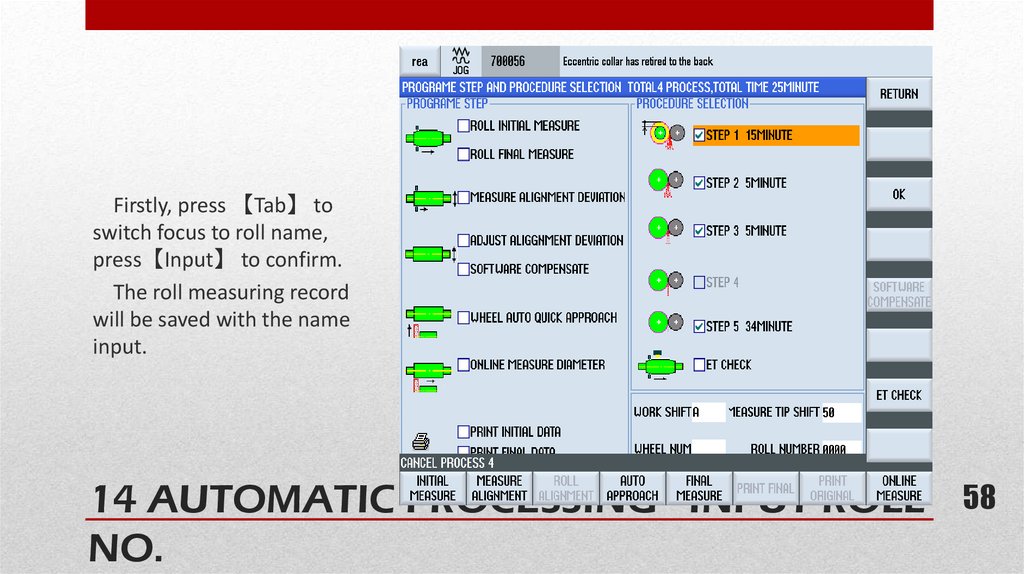
Firstly, press 【Tab】 toswitch focus to roll name,
press【Input】 to confirm.
The roll measuring record
will be saved with the name
input.
58
14 AUTOMATIC PROCESSING - INPUT ROLL
NO.
58
59.
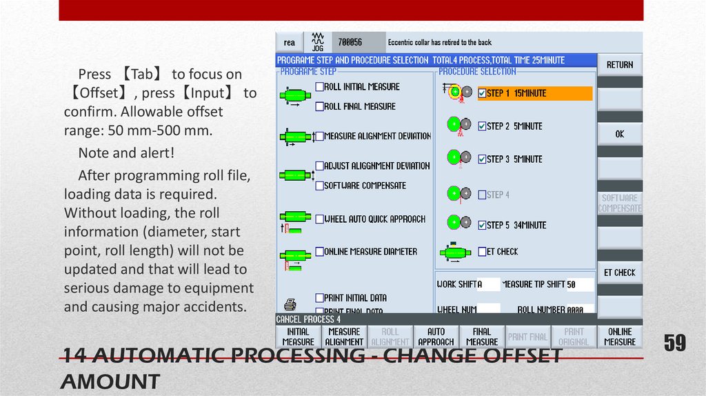
Press 【Tab】 to focus on【Offset】, press【Input】 to
confirm. Allowable offset
range: 50 mm-500 mm.
Note and alert!
After programming roll file,
loading data is required.
Without loading, the roll
information (diameter, start
point, roll length) will not be
updated and that will lead to
serious damage to equipment
and causing major accidents.
14 AUTOMATIC PROCESSING - CHANGE OFFSET
AMOUNT
59
59
60.
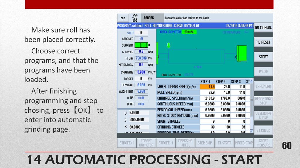
Make sure roll hasbeen placed correctly.
Choose correct
programs, and that the
programs have been
loaded.
After finishing
programming and step
chosing, press【OK】 to
enter into automatic
grinding page.
60
14 AUTOMATIC PROCESSING - START
60
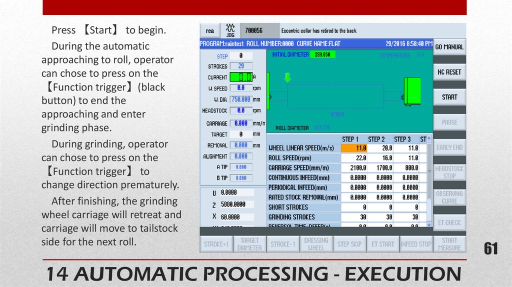
61.
Press 【Start】 to begin.During the automatic
approaching to roll, operator
can chose to press on the
【Function trigger】(black
button) to end the
approaching and enter
grinding phase.
During grinding, operator
can chose to press on the
【Function trigger】 to
change direction prematurely.
After finishing, the grinding
wheel carriage will retreat and
carriage will move to tailstock
side for the next roll.
61
14 AUTOMATIC PROCESSING - EXECUTION
61
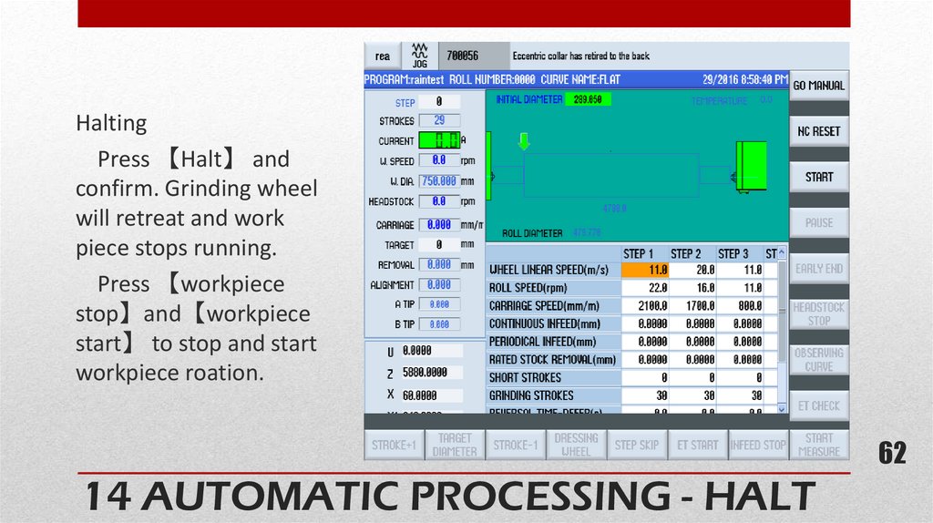
62.
HaltingPress 【Halt】 and
confirm. Grinding wheel
will retreat and work
piece stops running.
Press 【workpiece
stop】and【workpiece
start】 to stop and start
workpiece roation.
62
14 AUTOMATIC PROCESSING - HALT
62
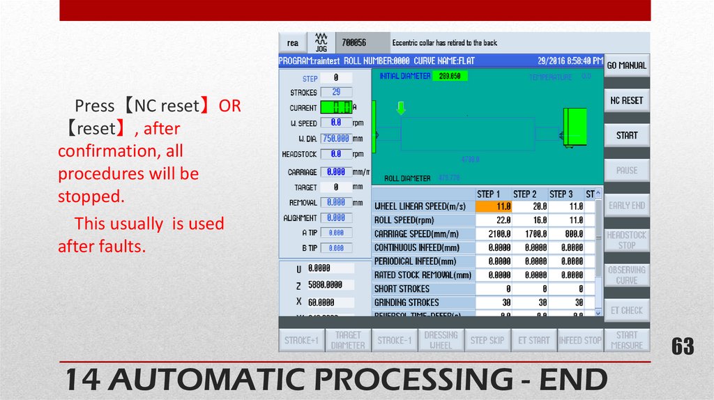
63.
Press【NC reset】OR【reset】, after
confirmation, all
procedures will be
stopped.
This usually is used
after faults.
63
14 AUTOMATIC PROCESSING - END
63
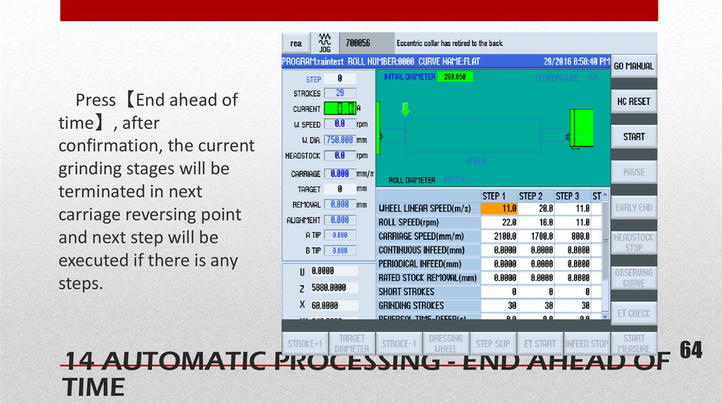
64.
Press【End ahead oftime】, after
confirmation, the current
grinding stages will be
terminated in next
carriage reversing point
and next step will be
executed if there is any
steps.
64
14 AUTOMATIC PROCESSING - END AHEAD OF
TIME
64
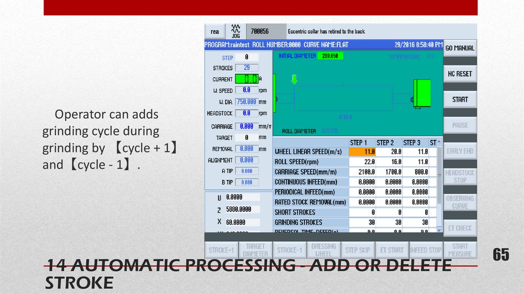
65.
Operator can addsgrinding cycle during
grinding by 【cycle + 1】
and【cycle - 1】.
14 AUTOMATIC PROCESSING - ADD OR DELETE
STROKE
65
65
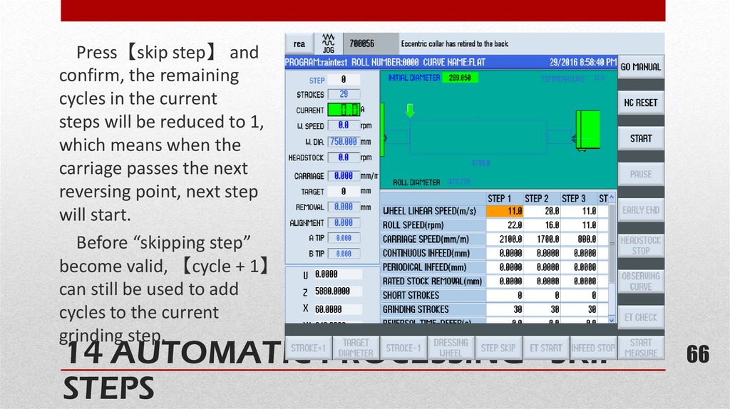
66.
Press【skip step】 andconfirm, the remaining
cycles in the current
steps will be reduced to 1,
which means when the
carriage passes the next
reversing point, next step
will start.
Before “skipping step”
become valid, 【cycle + 1】
can still be used to add
cycles to the current
grinding step.
14 AUTOMATIC PROCESSING - SKIP 66 66
STEPS
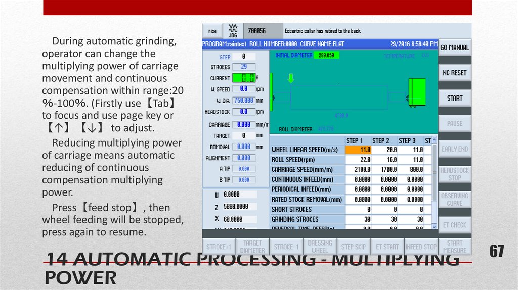
67.
During automatic grinding,operator can change the
multiplying power of carriage
movement and continuous
compensation within range:20
-100 . (Firstly use【Tab】
to focus and use page key or
【↑】【↓】 to adjust.
Reducing multiplying power
of carriage means automatic
reducing of continuous
compensation multiplying
power.
Press【feed stop】, then
wheel feeding will be stopped,
press again to resume.
67
14 AUTOMATIC PROCESSING - MULTIPLYING
POWER
67
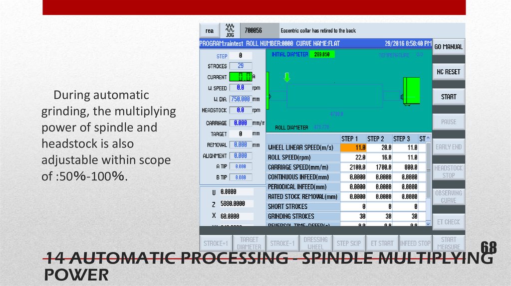
68.
During automaticgrinding, the multiplying
power of spindle and
headstock is also
adjustable within scope
of :50 -100 .
68
68
14 AUTOMATIC PROCESSING - SPINDLE MULTIPLYING
POWER
69.
(Only for grinders that areequipped with X1 axis)
When grinding roll body,
press【online measure】,
grinding wheel diameter
and stock removal will be
measured automatically.
Measuring arm B will be
put down and engage with
roll body when carriage is
moving left-ward, the
measure will be finished
when approaches middle
part.
The measuring results
will be displayed
immediately.
14 AUTOMATIC PROCESSING - MEASURE69
ONLINE
69
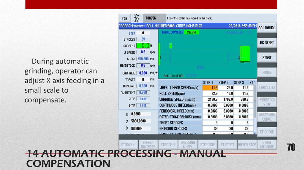
70.
During automaticgrinding, operator can
adjust X axis feeding in a
small scale to
compensate.
14 AUTOMATIC PROCESSING - MANUAL
COMPENSATION
70
70
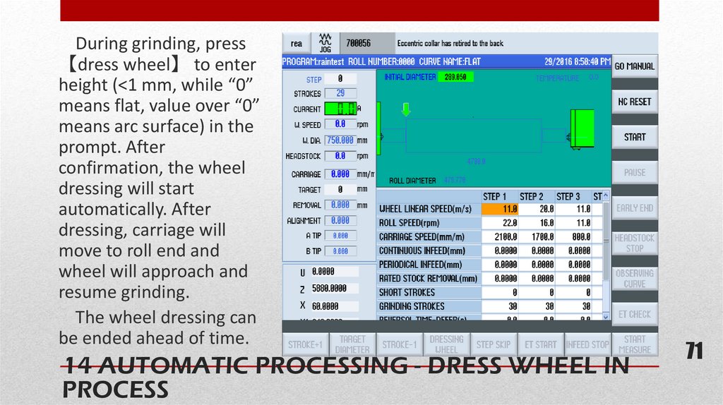
71.
During grinding, press【dress wheel】 to enter
height (<1 mm, while “0”
means flat, value over “0”
means arc surface) in the
prompt. After
confirmation, the wheel
dressing will start
automatically. After
dressing, carriage will
move to roll end and
wheel will approach and
resume grinding.
The wheel dressing can
be ended ahead of time.
14 AUTOMATIC PROCESSING - DRESS WHEEL IN
PROCESS
71
71
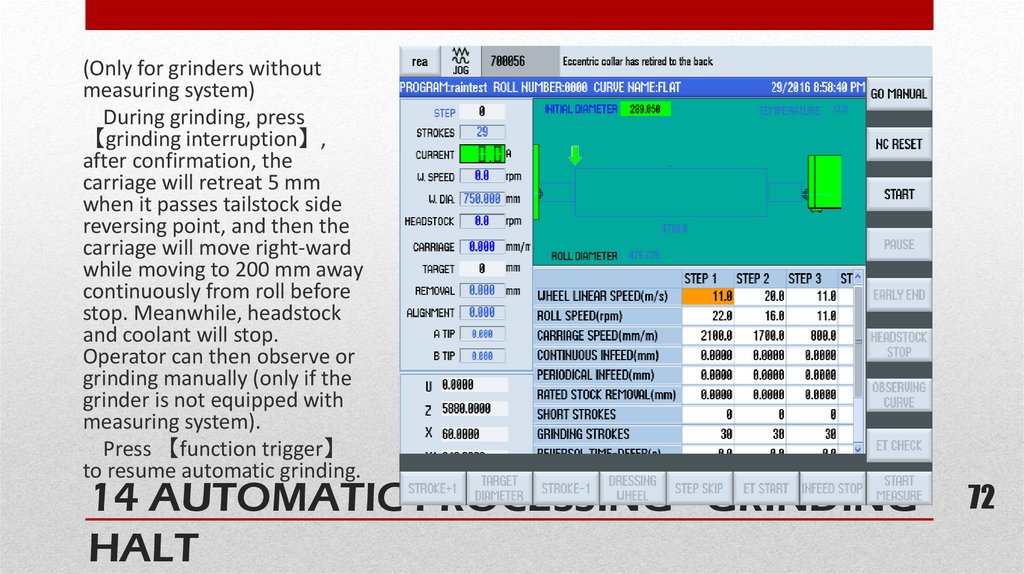
72.
(Only for grinders withoutmeasuring system)
During grinding, press
【grinding interruption】,
after confirmation, the
carriage will retreat 5 mm
when it passes tailstock side
reversing point, and then the
carriage will move right-ward
while moving to 200 mm away
continuously from roll before
stop. Meanwhile, headstock
and coolant will stop.
Operator can then observe or
grinding manually (only if the
grinder is not equipped with
measuring system).
Press 【function trigger】
to resume automatic grinding.
14 AUTOMATIC PROCESSING - GRINDING72
HALT
72
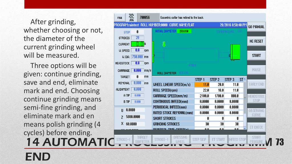
73.
After grinding,whether choosing or not,
the diameter of the
current grinding wheel
will be measured.
Three options will be
given: continue grinding,
save and end, eliminate
mark and end. Choosing
continue grinding means
semi-fine grinding, and
eliminate mark and en
means polish grinding (4
cycles) before ending.
73 73
14 AUTOMATIC PROCESSING - PROGRAMM
END
74.
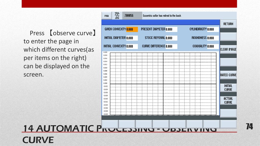
Press 【observe curve】to enter the page in
which different curves(as
per items on the right)
can be displayed on the
screen.
14 AUTOMATIC PROCESSING - OBSERVING
CURVE
74
74
75.
During automatic grinding, press【measure online】and confirm. Wheel will retreat 10 mm when passing
left roll end next time, measuring arm A will be put
down to measure. After measuring, the measuring
results will be displayed and operator can choose
whether to continue grinding. Choosing 【no】
measuring entering into measuring after grinding.
14 AUTOMATIC PROCESSING - MEASURE
ONLINE
75
76.
Firstly, activate the function by choosing the functionon flaw detection interface, input roll information and
press 【confirm】button on flaw detection interface.
On grinder interface, press 【flaw detection】 and
confirm. Wheel will retreat 10 mm when next time
passing left roll end, and then measuring arm A will be
put down to detect flaw and measure at the same time.
The process of flaw detection can be viewed online on
the flaw detection screen. Please refer to the flaw
detection manual for more details.
After this, operator can choose to continue grinding by
confirming by “Y” and enter measuring procedure by “N”.
14 AUTOMATIC PROCESSING - FLAW
DETECTION
76
77.
If the grinding current exceed the set amount for 5second and more, grinder will shut down.
When end feed exceed 0.2 mm, continuous feed
exceeds 0.5 mm, software protection will be in force and
further end feed and continuous feed will not effective.
If the protection switches of the measuring arms is
triggered, grinder will stop and alarms will be sent out.
In case of emergency, press on emergency stop button,
and the grinder will be stopped and cut off from power
supply.
14 AUTOMATIC PROCESSING - SAFETY
PROTECTION
77
78.
15 SHUTTING DOWN1.
2.
Dry run grinding wheel for at least 5 minutes before shutting down grinder;
Note: Make sure that all the movement and rotation (motor) stop before
shutting down grinder;
3. Turn the key to “off”;
4. Turn off grinder power;
5. Turn off UPS power.
★ Note
① There is a difference in shutting down grinder and turn off grinder. When
turning off grinder, control system is still on, the reference position is still
effective; while shutting down grinder means all the power of grinder is off
and reference position will be lost.
② Before shutting down the power supply, please make sure that the grinder
is turned off.
78
79.
17 AFTER SHUTTING DOWN1. Record as required and hand over as required;
2. Clean the environment around grinder area in workshop;
3. Clean grinder, for example, make sure of the cleanness of
grinding wheel bed cover.
79