
")
")
")


")
 География
Похожие презентации:


Investigation of midlatitude MSTIDs by ionosonde and dense GNSS-receivers’ network
1.
Investigation of midlatitude MSTIDsby ionosonde and dense GNSS-receivers’ network
Ruslan Sherstyukov, Adel Akchurin
1. Sodankyla Geophysical Observatory
2. Kazan Federal University
2.
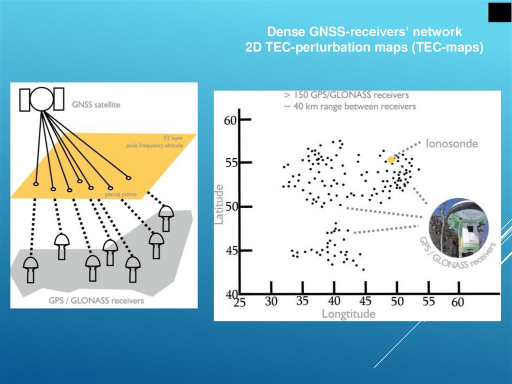
Dense GNSS-receivers’ network2D TEC-perturbation maps (TEC-maps)
3.
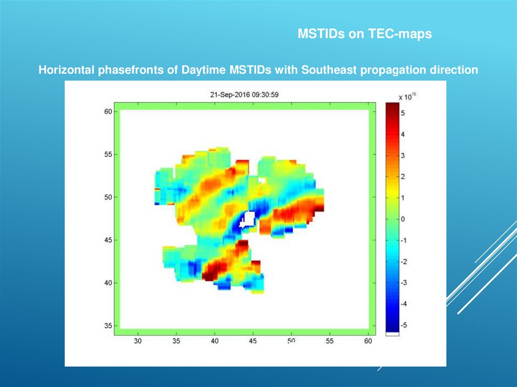
MSTIDs on TEC-mapsLatitude (°N)
Horizontal phasefronts of Daytime MSTIDs with Southeast propagation direction
Longitude (°E)
4.
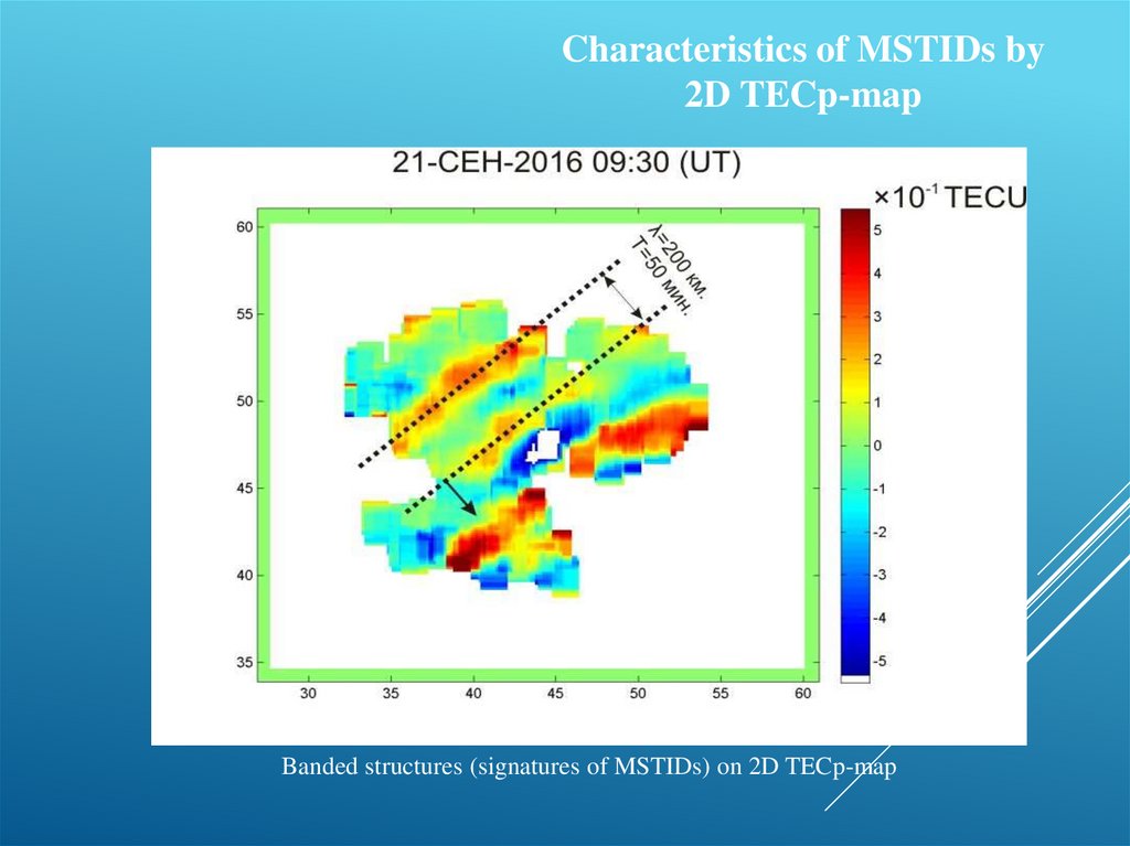
Characteristics of MSTIDs by2D TECp-map
Banded structures (signatures of MSTIDs) on 2D TECp-map
5.
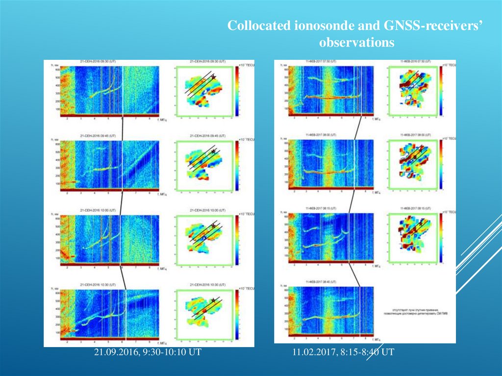
Collocated ionosonde and GNSS-receivers’observations
21.09.2016, 9:30-10:10 UT
11.02.2017, 8:15-8:40 UT
6.
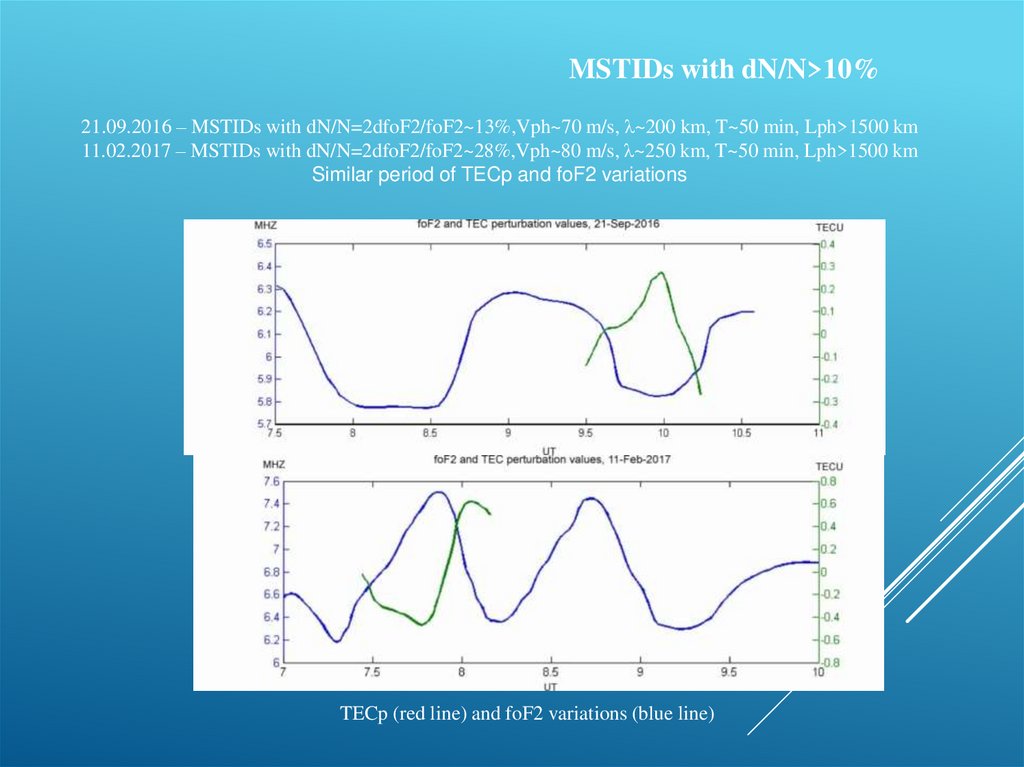
MSTIDs with dN/N>10%21.09.2016 – MSTIDs with dN/N=2dfoF2/foF2~13%,Vph~70 m/s, λ~200 km, T~50 min, Lph>1500 km
11.02.2017 – MSTIDs with dN/N=2dfoF2/foF2~28%,Vph~80 m/s, λ~250 km, T~50 min, Lph>1500 km
Similar period of TECp and foF2 variations
TECp (red line) and foF2 variations (blue line)
7.
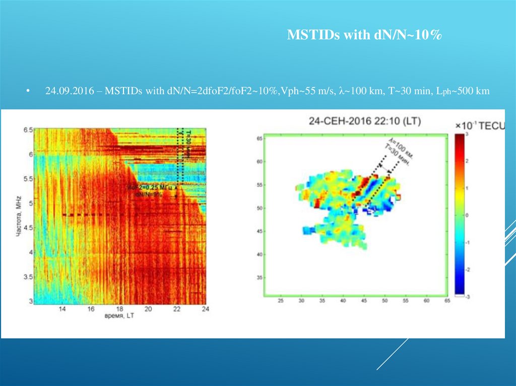
MSTIDs with dN/N~10%24.09.2016 – MSTIDs with dN/N=2dfoF2/foF2~10%,Vph~55 m/s, λ~100 km, T~30 min, Lph~500 km
8.
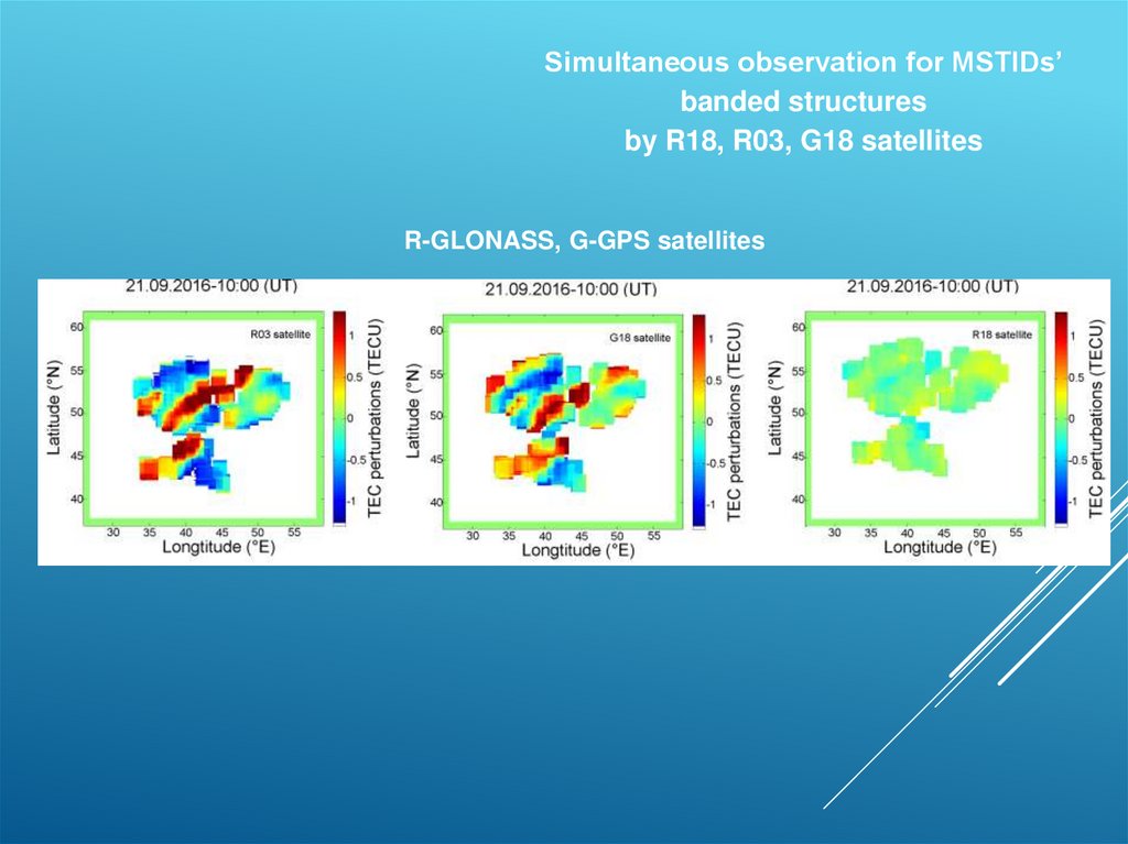
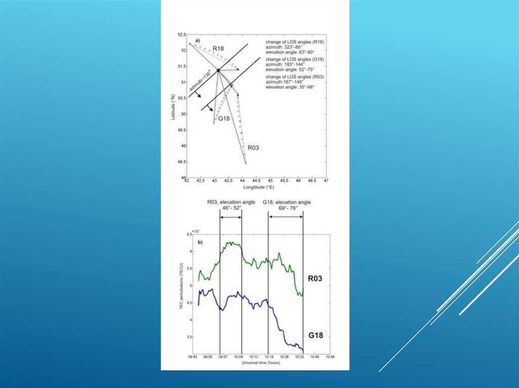
Simultaneous observation for MSTIDs’banded structures
by R18, R03, G18 satellites
R-GLONASS, G-GPS satellites
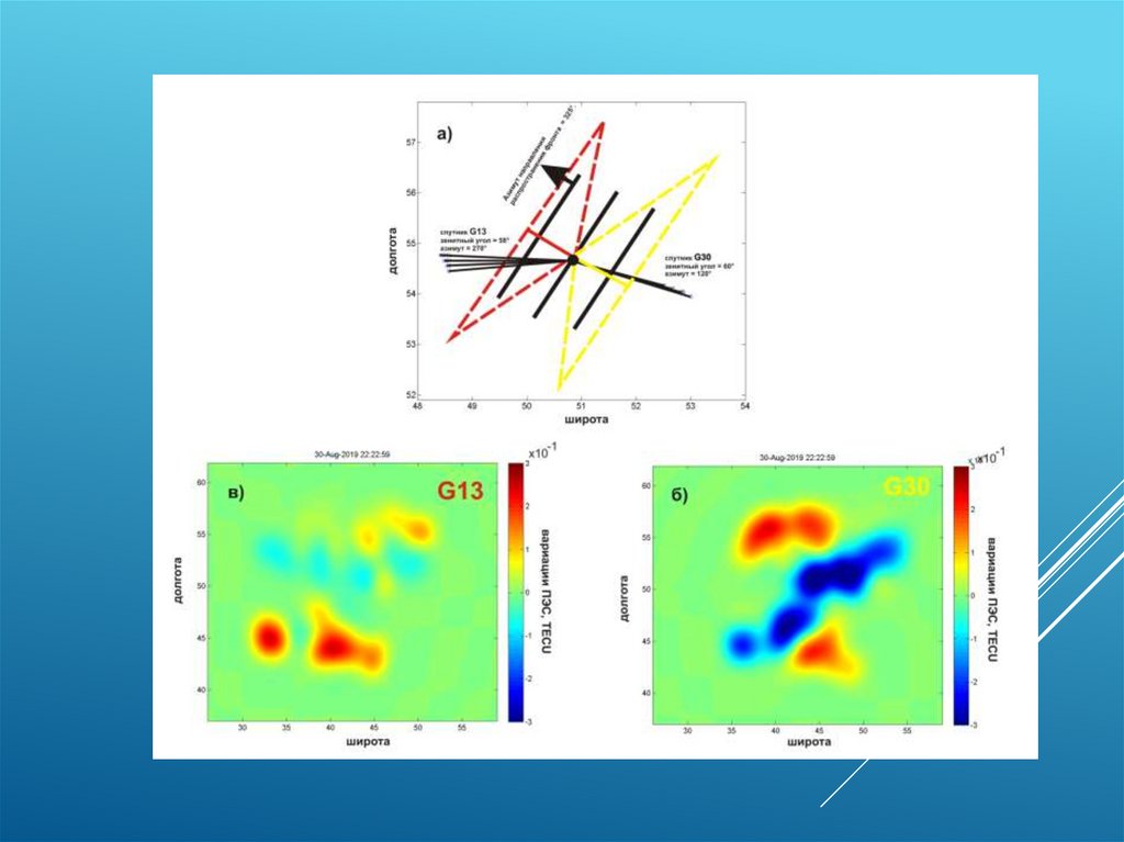
9. Influence of GNSS viewing angle on MSTIDs’ TEC perturbation amplitude
INFLUENCE OF GNSS VIEWING ANGLE ONMSTIDS’ TEC PERTURBATION AMPLITUDE
Relative arrangement of GNSS lines-of-sight (R18, R03, G18) and MSTIDs’ phasefront
(3D schematic figure and 2D experimental figure)
9
10.
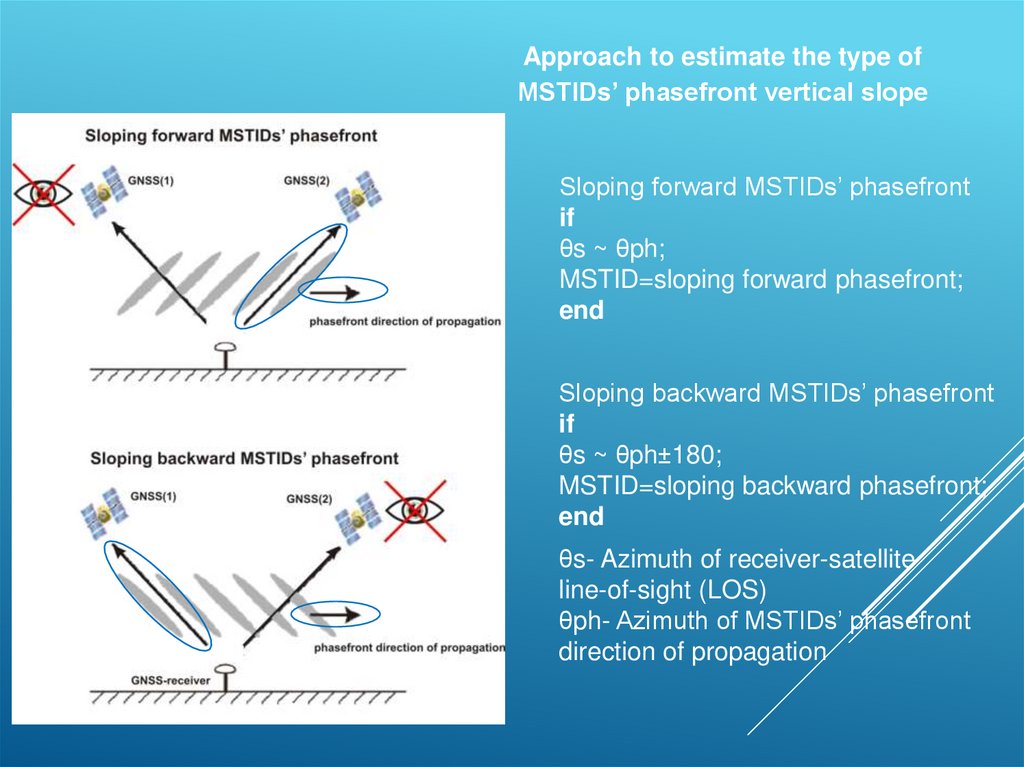
Approach to estimate the type ofMSTIDs’ phasefront vertical slope
Sloping forward MSTIDs’ phasefront
if
θs ~ θph;
MSTID=sloping forward phasefront;
end
Sloping backward MSTIDs’ phasefront
if
θs ~ θph±180;
MSTID=sloping backward phasefront;
end
θs- Azimuth of receiver-satellite
line-of-sight (LOS)
θph- Azimuth of MSTIDs’ phasefront
direction of propagation
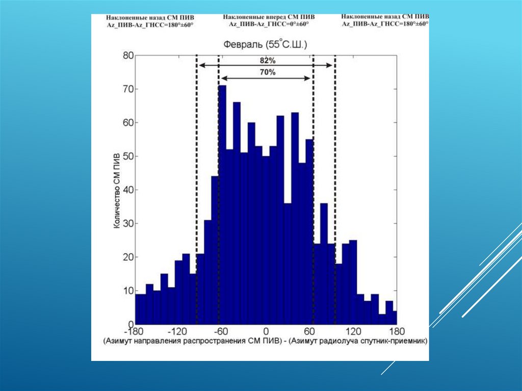
11. MSTIDs statistical study (February 2019)
MSTIDS STATISTICAL STUDY (FEBRUARY 2019)Statistics of MSTIDs’ phasefront
propagation directions
Statistics of MSTIDs’ phasefront
vertical slopes
11
12. MSTIDs statistical study (August, September 2020)
MSTIDS STATISTICAL STUDY(AUGUST, SEPTEMBER 2020)
VLBI array
Jacobson et al., 1995
Statistics of MSTIDs’
phasefront
propagation directions
13. MSTIDs statistical study (August 2020)
MSTIDS STATISTICAL STUDY(AUGUST 2020)
Statistics of MSTIDs’ phasefront vertical slopes
14.
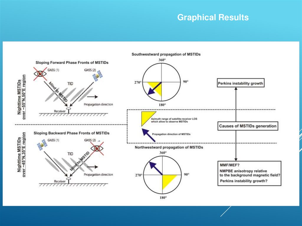
Graphical Results15.
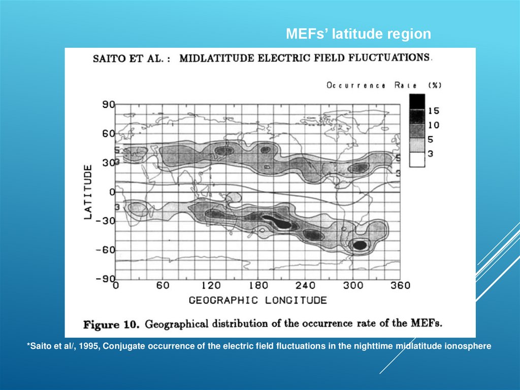
MEFs’ latitude region*Saito et al/, 1995, Conjugate occurrence of the electric field fluctuations in the nighttime midlatitude ionosphere
16.
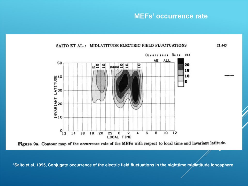
MEFs’ occurrence rate*Saito et al, 1995, Conjugate occurrence of the electric field fluctuations in the nighttime midlatitude ionosphere
17.
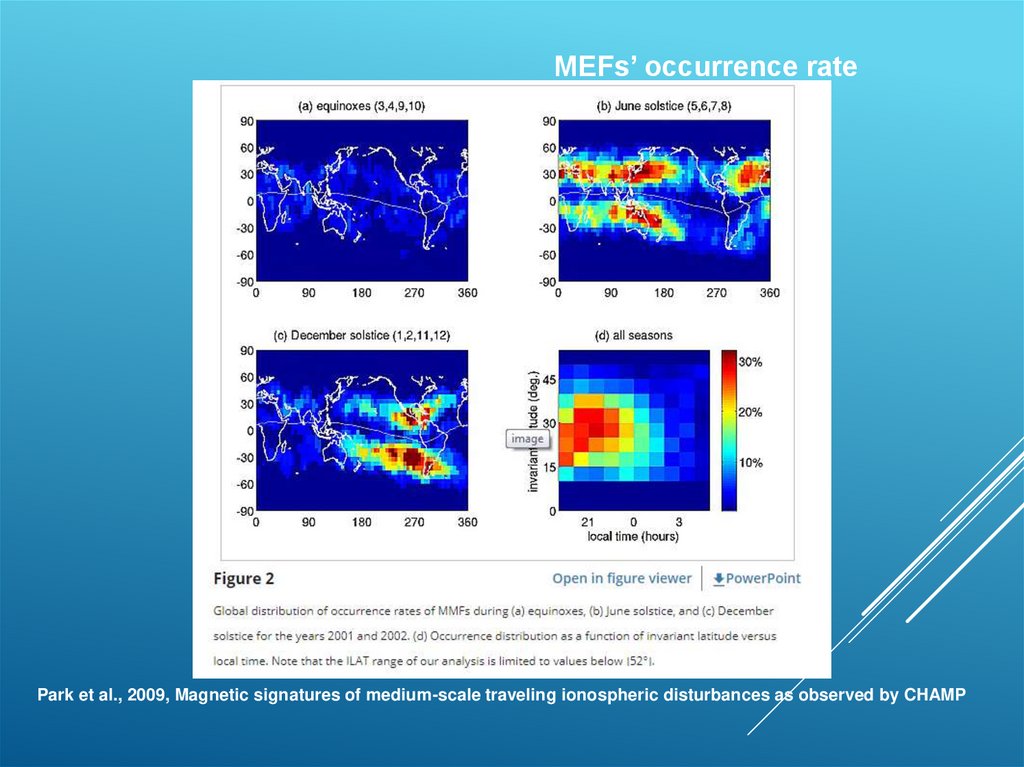
MEFs’ occurrence ratePark et al., 2009, Magnetic signatures of medium-scale traveling ionospheric disturbances as observed by CHAMP
18.
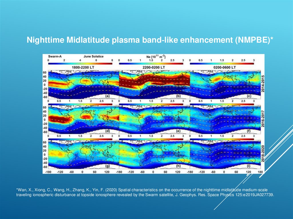
Nighttime Midlatitude plasma band‐like enhancement (NMPBE)**Wan, X., Xiong, C., Wang, H., Zhang, K., Yin, F. (2020) Spatial characteristics on the occurrence of the nighttime midlatitude medium-scale
traveling ionospheric disturbance at topside ionosphere revealed by the Swarm satellite, J. Geophys. Res. Space Physics 125:e2019JA027739.
19.
Conclusions1. Estimating the relative arrangement of satellite-receivers’ lines-of-sight and
MSTIDs’ phasefronts is a good tool for determining the statistics of MSTIDs’
vertical slopes.
2. The daytime MSTIDs in both latitudinal areas (45 and 55 degrees) are
observed with dominant southeastern propagation direction and sloping
forward phasefronts.
3. The nighttime MSTIDs’ propagation directions and vertical slopes in the areas
of 45 and 55 degrees latitude are distinguished (for August and September,
2020) . In the area of 55 degrees the nighttime MSTIDs were observed with
typical southwestern propagation directions and sloping forward phasefronts.
In the area of 45 degrees they were observed with northwestern propagation
directions and sloping backward phasefronts.
4. The causes of northwestward MSTIDs could be the Midlatitude Magnetic and
Electric Fields (MEFs/MMFs). The intensity of this MSTIDs could be
increased with the Nighttime Midlatitude plasma band-like enhancement
(NMPBE)
20. THANK YOU FOR ATTENTION!
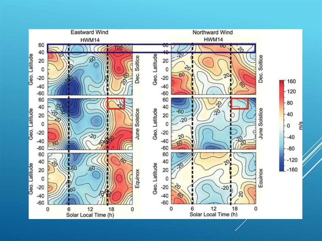
21. HWM14 model
HWM14 MODELНаправление распространения / время
Medvedev et al., 2017
Радар некогерентного рассеяния
22.
23.
24.
25. Calculation of MSTIDs vertical inclination angle ( vertical slope)
CALCULATION OF MSTIDS VERTICALINCLINATION ANGLE ( VERTICAL
SLOPE)
Variations of Average TECp by all receiver’s.
25
26.
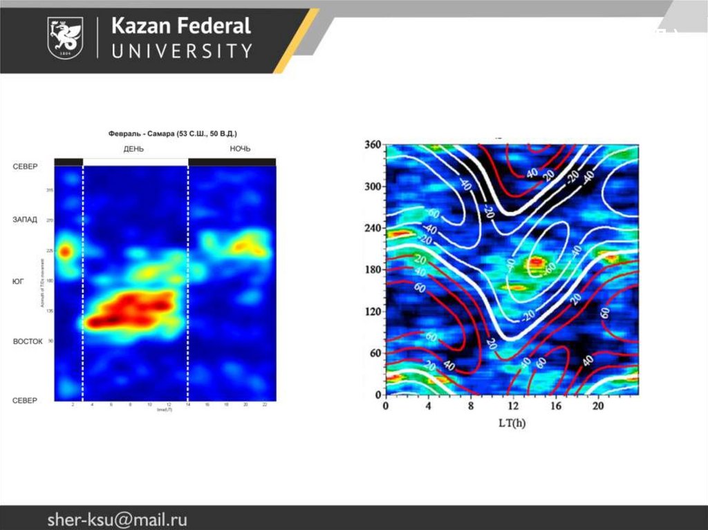
СМ ПИВ – Самара (53 С.Ш., 50 В.Д.)Февраль
GNSS observations (~55 N)
Medvedev et al., 2017
Incoherent scattering radar observations (~65 N)