


 Электроника
Похожие презентации:


Samsung For LED TV UE4,5 Series Training manual
1.
For LED TV UE4,5 SeriesUE22ES5000****
UE**EH50******
UE**EH52******
UE19ES4000W***
UE**EH4000W***
2.
Ⅰ.Concept
Ⅱ.
Specification
Ⅲ.
Product Image
Ⅳ.
Inner Feature
Ⅴ.
Disassemble
Ⅵ.
Troubleshooting
Ⅶ.
Feature
3.
Ⅰ. Product ConceptPicture Quality : Direct LED backlighting Panel
Design : Narrow Bezel
Experience : USB 2.0 Movie
Energy Saving : Low power consumption up to 40% of LCD TV
4.
Ⅱ. SpecificationSeries
Display
Video
Series
Ultra Clear Panel
Screen Size
Resolution
Dynamic Contrast Ratio
Picture Engine
Wide Color Enhancer Plus
100/200Hz Motion Plus
Clear Motion Rate
Precision Dimming
Dolby
Audio
Feature
SRS
dts 2.0 + Digital Out
SoUEd Output (RMS)
Speaker Type
Woofer
SamsUEg 3D
Anynet+ (HDMI-CEC)
Auto Channel Search
Auto Power Off
Auto Volume Leveler
BD Wise
Caption (Subtitle)
Clock & On/Off Timer
Allshare (Powerd by DLNA)
EPG
Game Mode
Internet@TV
Skype on SamsUEg TV
Picture-In-Picture
Sleep Timer
USB
WiFi Adaptor Support
User Interface
Extended PVR
Time Shift
Still Picture
Digital Noise Filter
Teletext (TTXT)
Wireless Remote Control
UE**E5000
No(Anti Glare)
22” / 32” / 40” / 46”
1920x 1080
MEGA
HyperReal Engine
Wide Color Enhancer Plus
No
120
No
Dolby Digital Plus/ Pulse
SRS TheaterSoUEd
Yes
22” 3W / 32”~ 10W x 2
Down Firing
No
No
No
Yes
Yes
Yes
No
Yes
Yes
No
No
Yes
No
No
No
Yes
Movie
No
Single UI
No
No
No
Yes
No
No
Series
System
Input & Output
Design
Power
Series
DTV Reception (DVB-T/T2/C/S2)
DTV TUEer Built-in
MHP/ MHEG (version)
Audio Out (Mini Jack)
Component In (Y/Pb/Pr)
Composite In (AV)
Digital Audio Out (Optical)
DVI Audio In (Mini Jack)
Ethernet (LAN)
Headphone
HDMI
PC Audio In (Mini Jack)
PC In (D-sub)
RF In
RS232C (AV CONTROL)
USB
CI Slot
Scart
Slim Type
Front Color
Light Effect (Deco)
Stand Type
Swivel (Left/Right)
Eco Mark
Eco Sensor
Power Supply
Power Consumption (Max.)
Power Consumption (Stand-by)
Package Size (W x D x H)
Dimension
Set Size (W x D x H) with Stand
Set Size (W x D x H)) without
Stand
Weight
Package Weight
Set Weight with Stand
Set Weight without Stand
UE**E5000
PAL
Yes
No
1
1
1 (Common use for Component Audio In)
1
0
0
0
2 (side v1.3)
1
0
1
Yes
1(side)
Yes
Yes
Normal
Black
No
Square
No
Energy Star
No
AC110-120V 60Hz
22” (TBD) / 32” (TBD) / 40” (TBD) / 46” (TBD)
0.3W
22” (585.0 x 475.0 x 120.0)
32” (902.0 x 162.0 x 530.0)
40” (1104.0 x 165.0 x 641.0)
46” (1237.0 x 165.0 x 723.0)
22” (513.4 x 364.4 x 161.0)
32” (738.3 x 498.1 x 191.6)
40” (927.6 x 606.4 x 227.6)
46” (1059.8 x 680.7 x 227.6)
22” (513.4 x 316.2 x 49.6)
32” (738.3 x 444.6 x 93.1)
40” (927.6 x 551.0 x 93.0)
46” (1059.8 x 625.6 x 94.3)
22” (4.9) / 32” (7.9) / 40” (13.5) / 46” (16.1)
22” (3.5) / 32” (6.4) / 40” (11.0) / 46” (14.0)
22” (3.3) / 32” (5.7) / 40” (9.0) / 46” (12.0)
-3/23-
5.
Ⅱ. SpecificationSeries
Display
Video
Series
Ultra Clear Panel
Screen Size
Resolution
Dynamic Contrast Ratio
Picture Engine
Wide Color Enhancer Plus
100/200Hz Motion Plus
Clear Motion Rate
Precision Dimming
Dolby
SRS
dts 2.0 + Digital Out
Audio
SoUEd Output (RMS)
Feature
Speaker Type
Woofer
SamsUEg 3D
Anynet+ (HDMI-CEC)
Auto Channel Search
Auto Power Off
Auto Volume Leveler
BD Wise
Caption (Subtitle)
Clock & On/Off Timer
Allshare (Powerd by DLNA)
EPG
Game Mode
Internet@TV
Skype on SamsUEg TV
Picture-In-Picture
Sleep Timer
USB
WiFi Adaptor Support
User Interface
Extended PVR
Time Shift
Still Picture
Digital Noise Filter
Teletext (TTXT)
Wireless Remote Control
UE**E4000
No(Anti Glare)
19” / 26” / 32”
1366 x 768
MEGA
HyperReal Engine
Wide Color Enhancer Plus
No
60
No
Dolby Digital Plus/ Pulse
SRS TheaterSoUEd
Yes
19” 3W X2
26” 5W X2
32”10W x 2
Down Firing
No
No
No
Yes
Yes
Yes
No
Yes
Yes
No
No
Yes
No
No
No
Yes
Movie
No
Single UI
No
No
No
Yes
No
No
“22
System
Input & Output
Design
Power
Series
DTV Reception (DVB-T/T2/C/S2)
DTV TUEer Built-in
MHP/ MHEG (version)
Audio Out (Mini Jack)
Component In (Y/Pb/Pr)
Composite In (AV)
Digital Audio Out (Optical)
DVI Audio In (Mini Jack)
Ethernet (LAN)
Headphone
HDMI
PC Audio In (Mini Jack)
PC In (D-sub)
RF In
RS232C (AV CONTROL)
USB
CI Slot
Scart
Slim Type
Front Color
Light Effect (Deco)
Stand Type
Swivel (Left/Right)
Eco Mark
Eco Sensor
Power Supply
Power Consumption (Max.)
Power Consumption (Stand-by)
Dimension
Weight
UE**E4000
PAL
Yes
No
1
1
1 (Common use for Component Audio In)
1
0
0
0
2 (side v1.3)
1
0
1
Yes
1(side)
No
No
Normal
Black
No
Square
No
Energy Star
No
AC110-120V 60Hz
19” (TBD) / 26” (TBD) / 32” (TBD)
0.3W
Package Size (W x D x H)
19” (514.0 x 424.0 x 125.0)
26” ( 770.0 x 162.0 x 445.0)
32” (902.0 x 162.0 x 5300)
Set Size (W x D x H) with Stand
22” (446.8 x 326.9 x 161.0)
26” ( 615.1 x 419.2 x 180.7)
32” (738.8 x 493.3 x 191.7)
Set Size (W x D x H)) without
Stand
22” (446.8 x 278.7 x 49.6)
26” ( 615.1 x 365.6 x 93.3)
32” (738.8 x 436.7 x 93.3)
Package Weight
Set Weight with Stand
Set Weight without Stand
22” (4.1) / 26” (5.70) / 32” (7.90)
22” (3.0) / 26” (4.50) / 32” (6.30)
22” (2.7) / 26” (4.00) / 32” (5.70)
-3/23-
6.
Ⅱ. SpecificationSpec. Comparison
Model
UD5R
UE5L
30.2 x 18.4 x 1.2 (32”)
29.1 x 17.5 x 3.7 (32”)
15.88 lbs (32”)
12.57 lbs(40”)
Size
Diagonal 32”
Diagonal 32”
Resolution
1920 x 1080
1920 x 1080
Hz
60
60
Design
Set
Size(without stand)
Panel
Viewing angle
H : 176
V : 176
H : 176
V : 176
Color System
PAL
PAL
TUEer
1
1
Contrast (cd/m2)
450
TBD
CR ( Dynamic )
MEGA
MEGA
Enhancer
HyperReal Engine (X5)
HyperReal Engine (X9)
Edge LED
Direct LED
Function
Back light UEit
ANYNET+
Additional Function
TOUCH FuncTION
JOG FUETION
Power Consumption
80W
TBD
-3/23-
7.
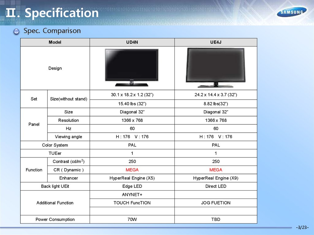
Ⅱ. SpecificationSpec. Comparison
Model
UD4N
UE4J
30.1 x 18.2 x 1.2 (32”)
24.2 x 14.4 x 3.7 (32”)
15.40 lbs (32”)
8.82 lbs(32”)
Size
Diagonal 32”
Diagonal 32”
Resolution
1366 x 768
1366 x 768
Hz
60
60
Design
Set
Size(without stand)
Panel
Viewing angle
H : 176
V : 176
H : 176
V : 176
Color System
PAL
PAL
TUEer
1
1
Contrast (cd/m2)
250
250
CR ( Dynamic )
MEGA
MEGA
Enhancer
HyperReal Engine (X5)
HyperReal Engine (X9)
Edge LED
Direct LED
Function
Back light UEit
ANYNET+
Additional Function
TOUCH FuncTION
JOG FUETION
Power Consumption
70W
TBD
-3/23-
8.
Ⅲ. DesignTV Controller
9.
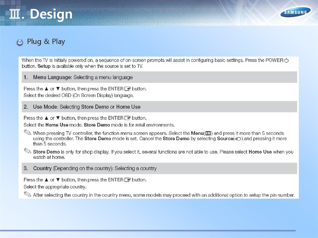
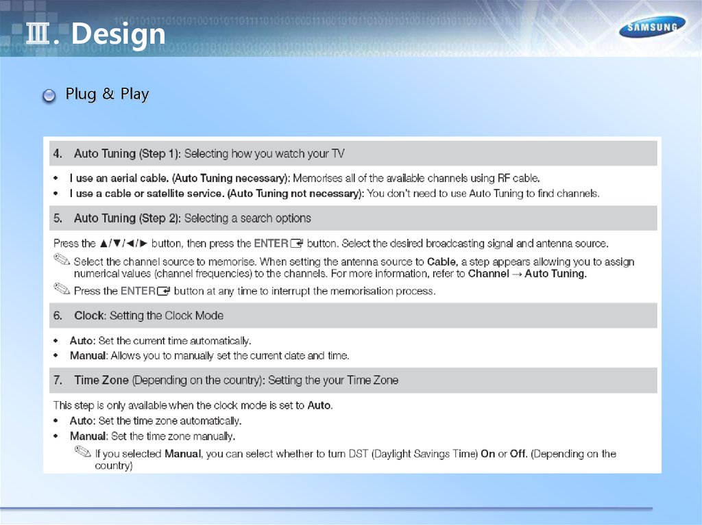
Ⅲ. DesignPlug & Play
10.
Ⅲ. DesignPlug & Play
11.
Ⅲ. DesignPlug & Play
12.
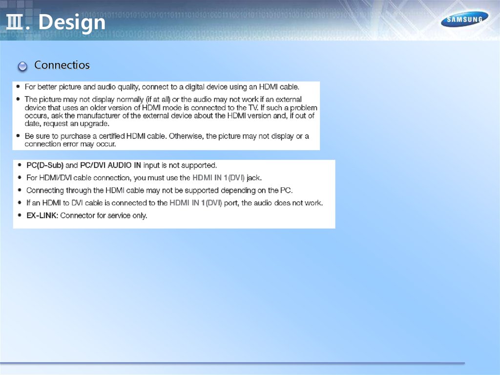
Ⅲ. DesignConnectios
13.
Ⅲ. DesignConnectios
14.
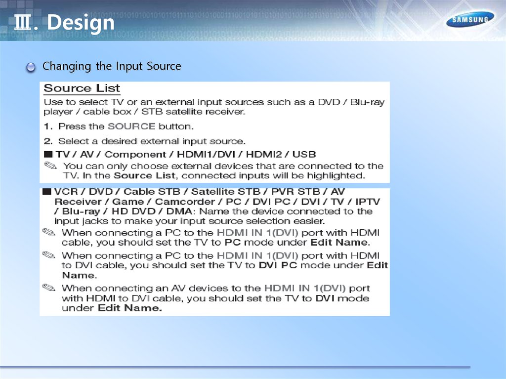
Ⅲ. DesignChanging the Input Source
15.
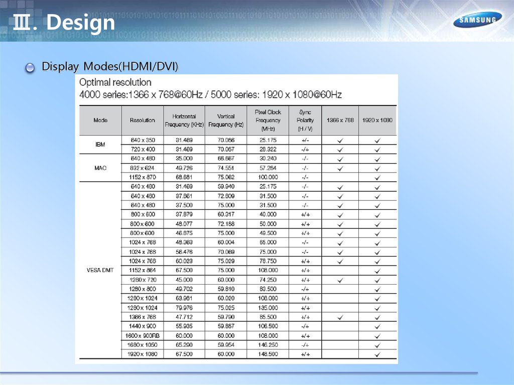
Ⅲ. DesignDisplay Modes(HDMI/DVI)
16.
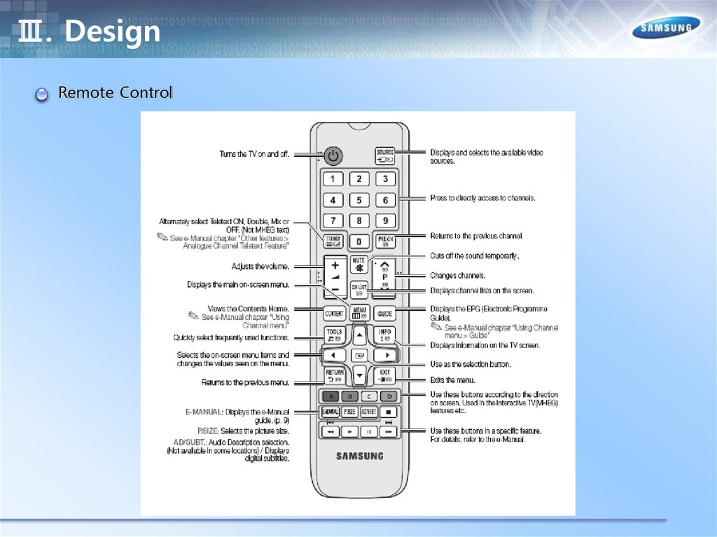
Ⅲ. DesignRemote Control
17.
Ⅲ. DesignViewing Front – UE22ES5000
-Speakers
- Remote Control
Sensor
- Power Indicator
- Jog Function
18.
Ⅲ. DesignRear – UE22ES5000
19.
Ⅲ. DesignViewing Front - UE32EH5000
-Speakers
- Remote Control
Sensor
- Power Indicator
- Jog Function
20.
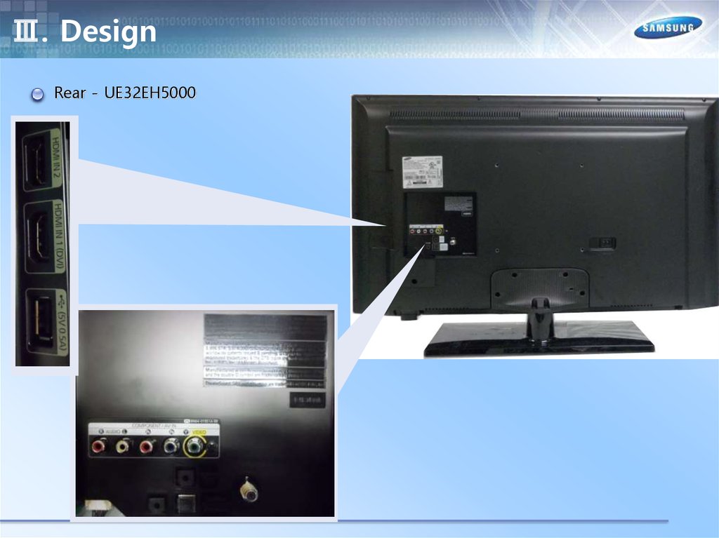
Ⅲ. DesignRear - UE32EH5000
21.
Ⅲ. DesignViewing Front - UE40EH5000
- Speakers
- Remote Control
Sensor
- Power Indicator
- Jog Function
22.
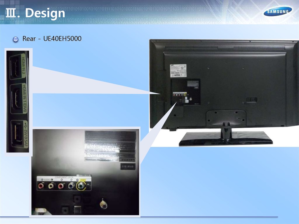
Ⅲ. DesignRear - UE40EH5000
23.
Ⅲ. DesignViewing Front - UE46EH5000
-Speakers
- Remote Control
Sensor
- Power Indicator
- Jog Function
24.
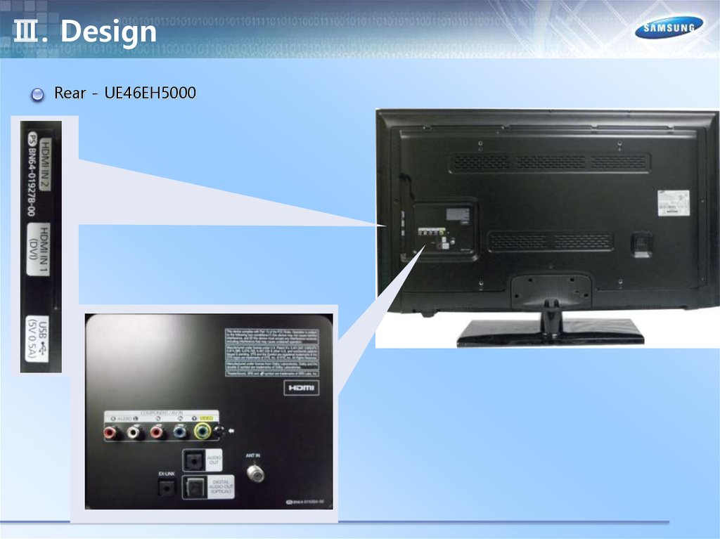
Ⅲ. DesignRear - UE46EH5000
25.
Ⅲ. DesignViewing Front – UE19ES4000
-Speakers
- Remote Control
Sensor
- Power Indicator
- Jog Function
26.
Ⅲ. DesignRear – UE19ES4000
27.
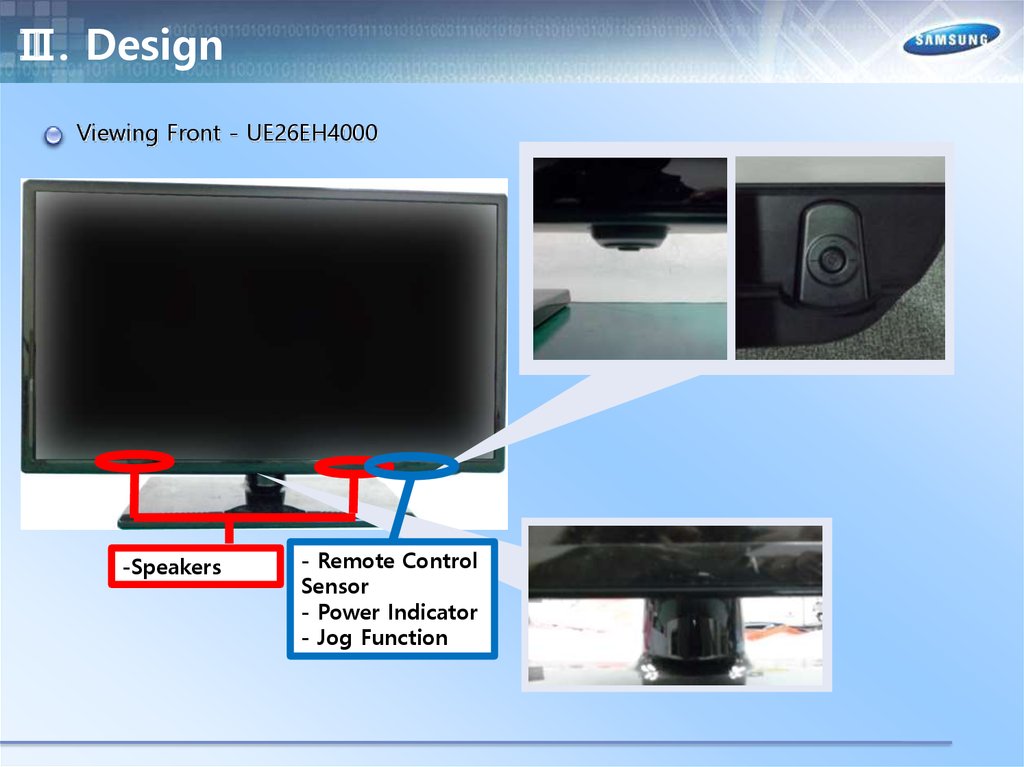
Ⅲ. DesignViewing Front - UE26EH4000
-Speakers
- Remote Control
Sensor
- Power Indicator
- Jog Function
28.
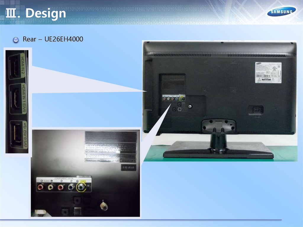
Ⅲ. DesignRear – UE26EH4000
29.
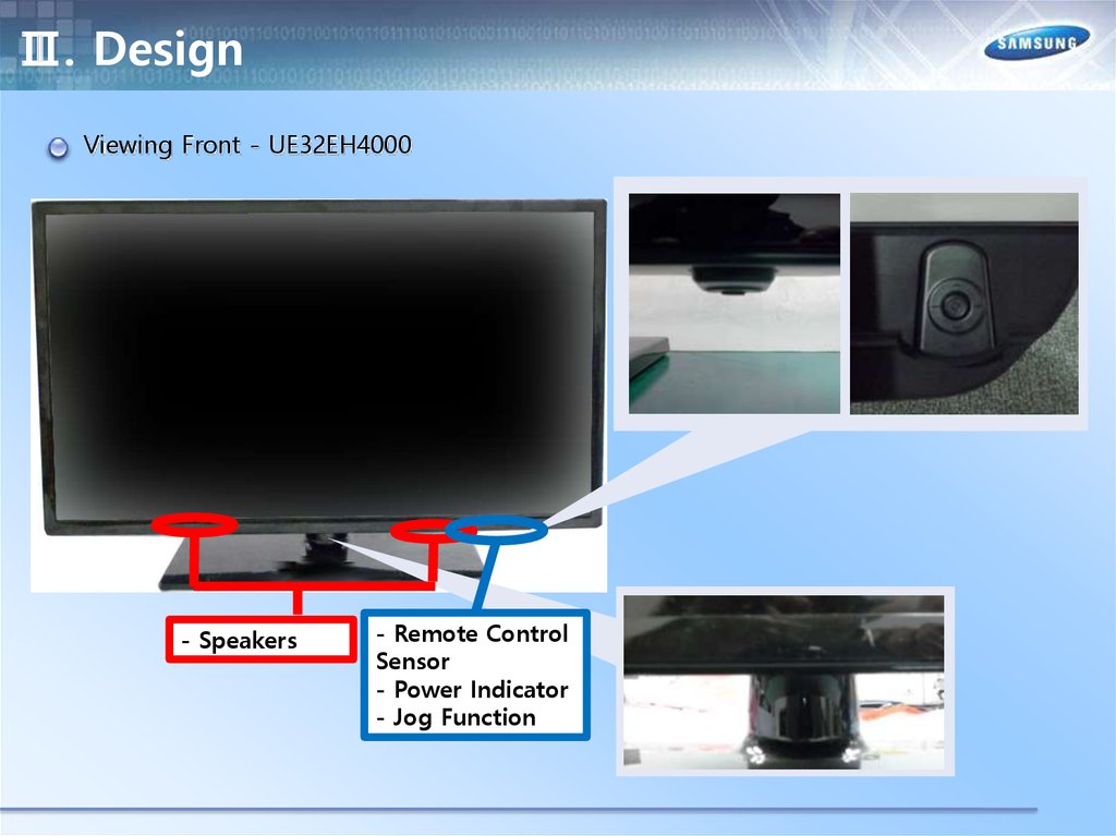
Ⅲ. DesignViewing Front - UE32EH4000
- Speakers
- Remote Control
Sensor
- Power Indicator
- Jog Function
30.
Ⅲ. DesignRear - UE32EH4000
31.
Ⅳ. Inner FeatureLAY OUT – UE19ES5000
SMPS Board
Main Board
Speaker (R)
Speaker (L)
32.
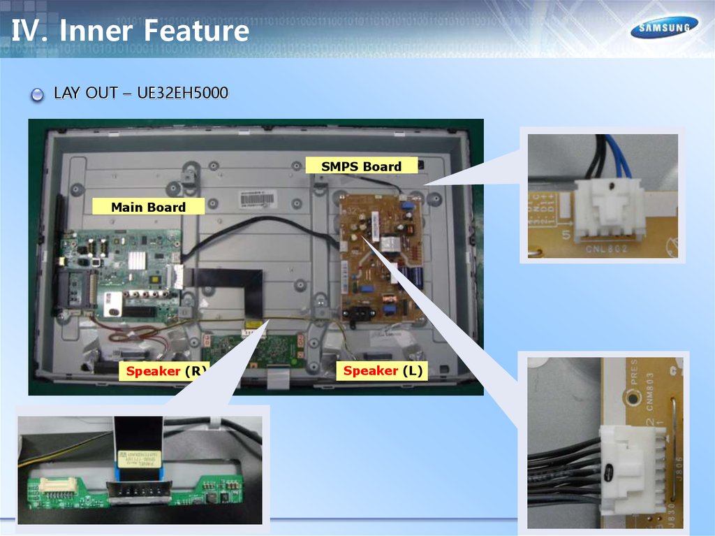
Ⅳ. Inner FeatureLAY OUT – UE32EH5000
SMPS Board
Main Board
Speaker (R)
Speaker (L)
33.
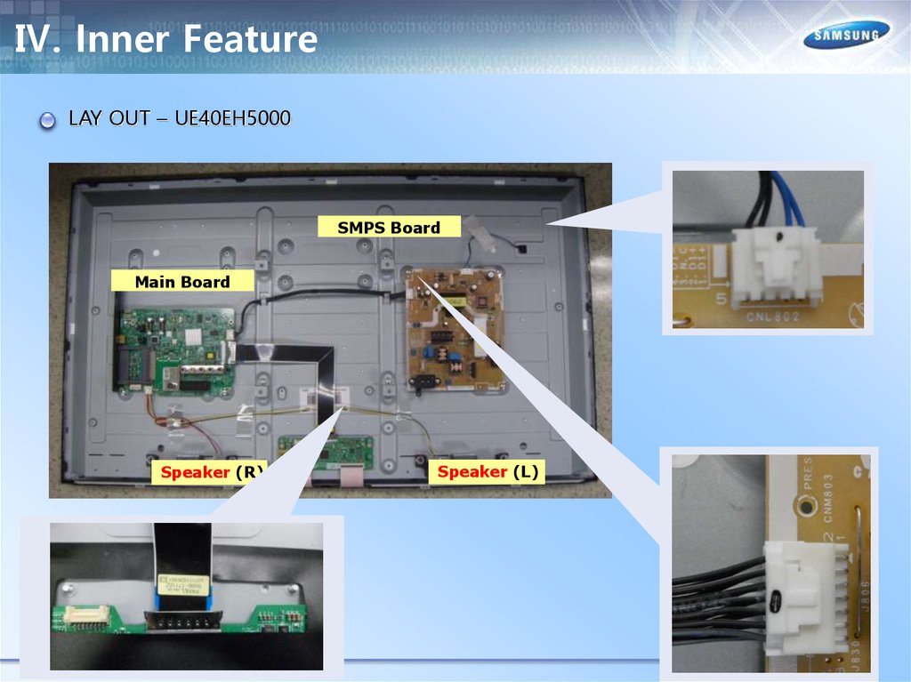
Ⅳ. Inner FeatureLAY OUT – UE40EH5000
SMPS Board
Main Board
Speaker (R)
Speaker (L)
34.
Ⅳ. Inner FeatureLAY OUT – UE46EH5000
SMPS Board
Main Board
Speaker (R)
Speaker (L)
35.
Ⅳ. Inner FeatureLAY OUT – UE19ES4000
SMPS Board
Main Board
Speaker (R)
Speaker (L)
36.
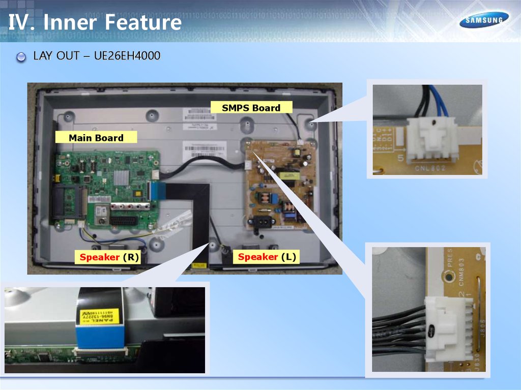
Ⅳ. Inner FeatureLAY OUT – UE26EH4000
SMPS Board
Main Board
Speaker (R)
Speaker (L)
37.
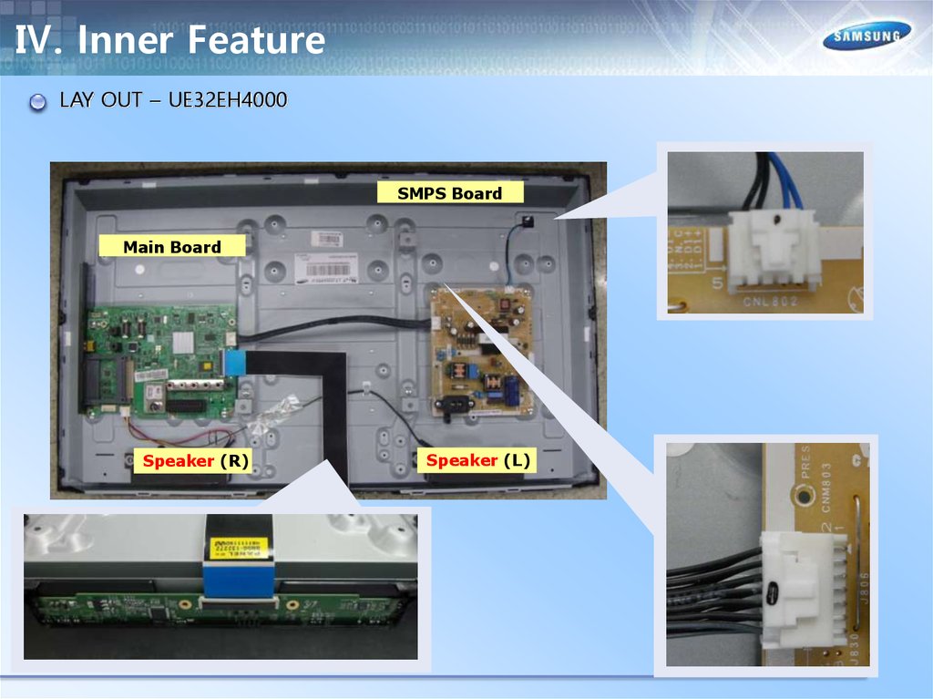
Ⅳ. Inner FeatureLAY OUT – UE32EH4000
SMPS Board
Main Board
Speaker (R)
Speaker (L)
38.
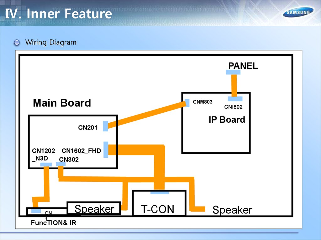
Ⅳ. Inner FeatureWiring Diagram
PANEL
Main Board
CNM803
CNI802
IP Board
CN201
CN1202 CN1602_FHD
_N3D
CN302
CN
1
Speaker
FuncTION& IR
T-CON
Speaker
39.
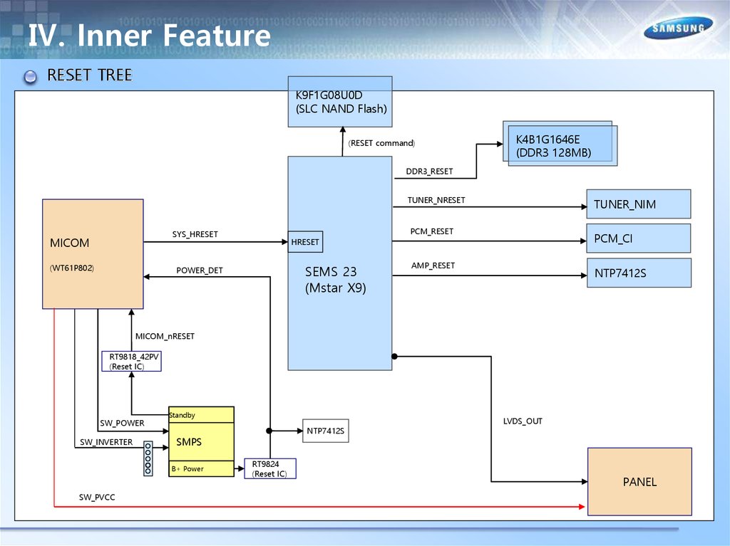
Ⅳ. Inner FeatureRESET TREE
K9F1G08U0D
(SLC NAND Flash)
(RESET command)
K4B1G1646E
(DDR3 128MB)
DDR3_RESET
TUNER_NRESET
PCM_RESET
SYS_HRESET
MICOM
(WT61P802)
TUNER_NIM
PCM_CI
HRESET
SEMS 23
(Mstar X9)
POWER_DET
AMP_RESET
NTP7412S
MICOM_nRESET
RT9818_42PV
(Reset IC)
SW_POWER
SW_INVERTER
Standby
SMPS
B+ Power
SW_PVCC
NTP7412S
RT9824
(Reset IC)
LVDS_OUT
PANEL
40.
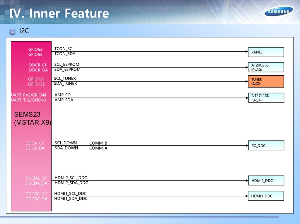
Ⅳ. Inner FeatureI2C
GPIO52
GPIO58
TCON_SCL
TCON_SDA
PANEL
DDCR_CK
DDCR_DA
SCL_EEPROM
SDA_EEPROM
AT24C256
(0xA0)
GPIO131
GPIO132
SCL_TUNER
SDA_TUNER
TUNER
(0xC0)
AMP_SCL
AMP_SDA
NTP7412S
(0x54)
UART_RX2/GPIO44
UART_TX2/GPIO43
SEMS23
(MSTAR X9)
DDCA_CK
DDCA_DA
SCL_DOWN
SDA_DOWN
DDCDA_CK
DDCDA_DA
HDMI2_SCL_DDC
HDMI2_SDA_DDC
HDMI2_DDC
DDCDC_CK
DDCDC_DA
HDMI1_SCL_DDC
HDMI1_SDA_DDC
HDMI1_DDC
COMM_B
COMM_A
PC_DDC
41.
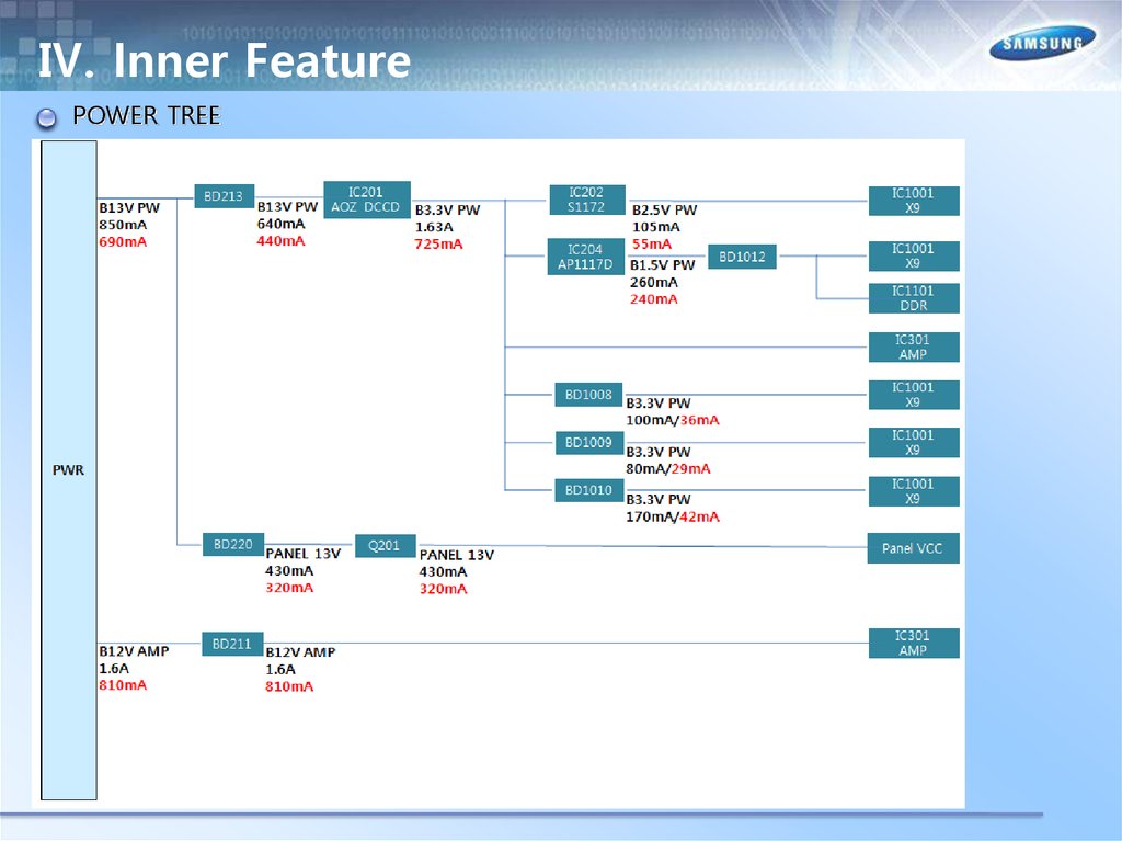
Ⅳ. Inner FeaturePOWER TREE
A5V
#4
A5V
A5V
A3. 3V
BD207
201 mA
IC202
S-1206B33
A3. 3V
A3. 3V
A3. 3V
A3. 3V
1500 mA
B13V
B13V
#11,13
BD212
IC204
AOZ1051
BD203
1800mA
B5. 3V
B3. 3V
BD211
IC201
AOZ1051
B1. 2V
BD202
B5V
#1,3
T2/ISDB-T Opt i on
BD706
BD705
B13V
Q201
AO6415
IC203
MM3374A25
B2. 5V
DC/DC
RT8083
1800 mA
B12VS B12VS
#7,9
BD206
Function / IR
IC1201 (SUBMICOM)
IC1203 (SUB EEPROM)
PANEL VCC (T- CON)
IC1001 X9
B1. 2V
B1. 5V_DDR
IC705_FN
G9915-12
IC707
AP1117-ADJ
B1. 2V_TU
IC708_TC
AP1117-D18
B1. 8V_TU
B3. 3V_TU
B3. 3V
B3. 3V
DC/DC
RT8083
IC302 (RT9824)
B3. 3V
IC205
AP1117-ADJ
BD1301
IC1204 (RT9818C- 42V)
IC1101,1102
256M DDR3
TU701_TU
Tuner
IC901 Main EEPROM
CI logic IC
B3. 3V
IC1301 2G NAND
B3. 3V
IC301 NTP7412S
B5V
USB
B5V
CI
B12VS
IC301 NTP7412
42.
Ⅳ. Inner FeaturePOWER TREE
43.
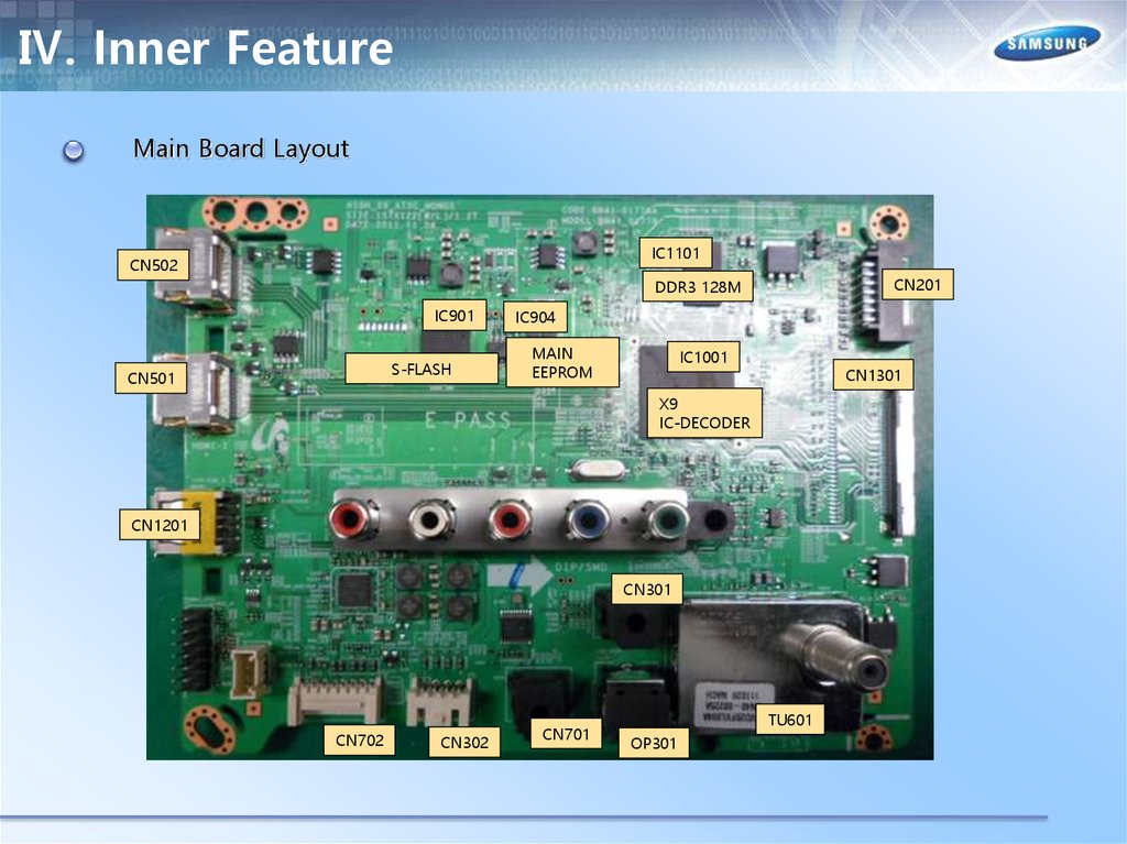
Ⅳ. Inner FeatureMain Board Layout
IC1101
CN502
CN201
DDR3 128M
IC901
S-FLASH
CN501
IC904
MAIN
EEPROM
IC1001
CN1301
X9
IC-DECODER
CN1201
CN301
CN702
CN302
CN701
TU601
OP301
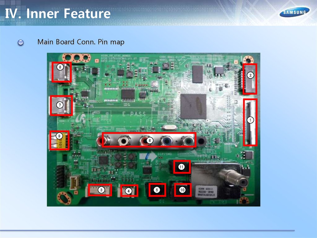
44.
Ⅳ. Inner FeatureMain Board Conn. Pin map
8
2
7
1
9
6
11
3
4
5
10
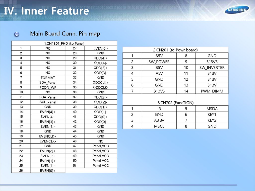
45.
Ⅳ. Inner FeatureMain Board Conn. Pin map
1
2
3
4
5
6
7
8
9
10
11
12
13
14
15
16
17
18
19
20
21
22
23
24
25
26
1.CN1301_FHD (to Panel)
NC
27
NC
28
NC
29
NC
30
NC
31
NC
32
33
FORMAT
SDA_Panel
34
TCON_WP
35
NC
36
SDA_Panel
37
SCL_Panel
38
GND
39
EVEN[4]+
40
EVEN[4]41
EVEN[3]+
42
EVEN[3]43
GND
44
EVENCLK+
45
EVENCLK46
GND
47
EVEN[2]+
48
EVEN[2]49
EVEN[1]+
50
EVEN[1]51
EVEN[0]+
EVEN[0]GND
ODD[4]+
ODD[4]ODD[3]+
ODD[3]GND
ODDCLK+
ODDCLKGND
ODD[2]+
ODD[2]ODD[1]+
ODD[1]ODD[0]+
ODD[0]GND
GND
GND
NC
Panel_VCC
Panel_VCC
Panel_VCC
Panel_VCC
Panel_VCC
1
2
3
4
5
6
7
1
2
3
4
2.CN201 (to Powr board)
B5V
8
GND
SW_POWER
9
B13VS
B5V
10
SW_INVERTER
A5V
11
B13V
GND
12
B13V
GND
13
B13V
B13VS
14
PWM_DIMM
3.CN702 (FuncTION)
IR
5
GND
6
A3.3V
7
MSCL
8
MSDA
KEY1
KEY2
GND
46.
Ⅳ. Inner FeatureMain Board Conn. Pin map
1
2
1
2
3
1
2
3
4
5
6
7
8
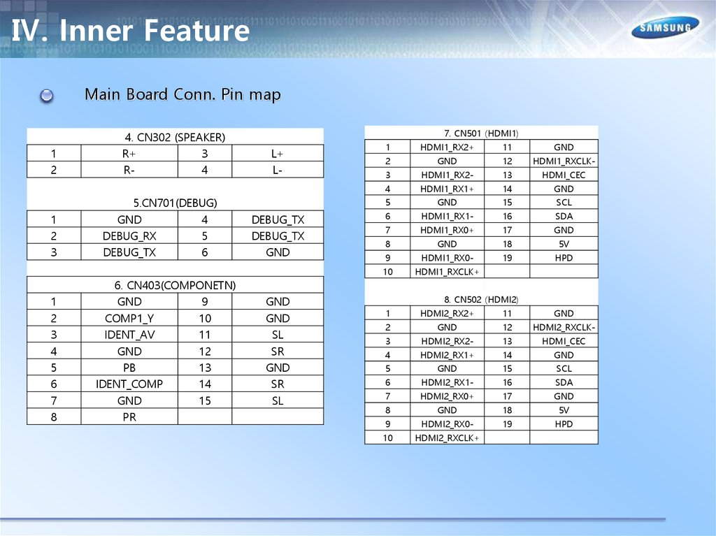
4. CN302 (SPEAKER)
R+
3
R4
5.CN701(DEBUG)
GND
4
DEBUG_RX
5
DEBUG_TX
6
6. CN403(COMPONETN)
GND
9
COMP1_Y
10
IDENT_AV
11
GND
12
PB
13
IDENT_COMP
14
GND
15
PR
7. CN501 (HDMI1)
L+
L-
DEBUG_TX
DEBUG_TX
GND
GND
GND
SL
SR
GND
SR
SL
1
HDMI1_RX2+
11
GND
2
GND
12
HDMI1_RXCLK-
3
HDMI1_RX2-
13
HDMI_CEC
4
HDMI1_RX1+
14
GND
5
GND
15
SCL
6
HDMI1_RX1-
16
SDA
7
HDMI1_RX0+
17
GND
8
GND
18
5V
9
HDMI1_RX0-
19
HPD
10
HDMI1_RXCLK+
1
HDMI2_RX2+
11
GND
2
GND
12
HDMI2_RXCLK-
3
HDMI2_RX2-
13
HDMI_CEC
4
HDMI2_RX1+
14
GND
5
GND
15
SCL
6
HDMI2_RX1-
16
SDA
7
HDMI2_RX0+
17
GND
8
GND
18
5V
9
HDMI2_RX0-
19
HPD
10
HDMI2_RXCLK+
8. CN502 (HDMI2)
47.
Ⅳ. Inner FeatureMain Board Conn. Pin map
1
2
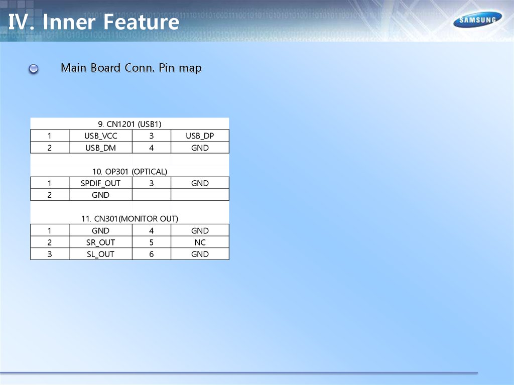
9. CN1201 (USB1)
USB_VCC
3
USB_DM
4
1
2
10. OP301 (OPTICAL)
SPDIF_OUT
3
GND
1
2
3
11. CN301(MONITOR OUT)
GND
4
SR_OUT
5
SL_OUT
6
USB_DP
GND
GND
GND
NC
GND
48.
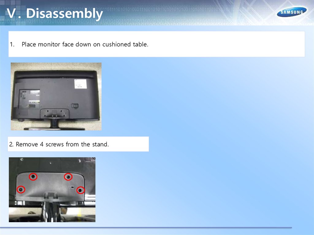
Ⅴ. Disassembly1.
Place monitor face down on cushioned table.
2. Remove 4 screws from the stand.
49.
Ⅴ. Disassembly3. Remove stand.
4. 32/40" : Remove 1 screw of cover jack
46" : Remove 9 screws of rear cover.
32/40
46
50.
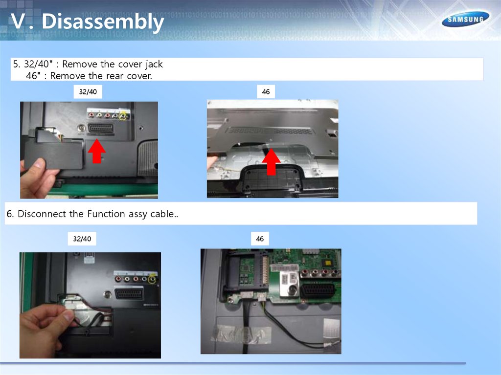
Ⅴ. Disassembly5. 32/40" : Remove the cover jack
46" : Remove the rear cover.
32/40
46
6. Disconnect the Function assy cable..
32/40
46
51.
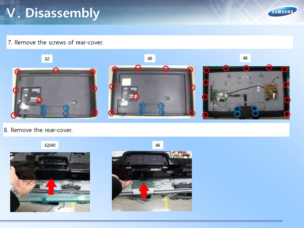
Ⅴ. Disassembly7. Remove the screws of rear-cover.
32
46
40
8. Remove the rear-cover.
32/40
46
52.
Ⅴ. Disassembly9.Remove the screws of main board and IP board and Panel.
32
10. Remove the speakers and power cables
40
46
53.
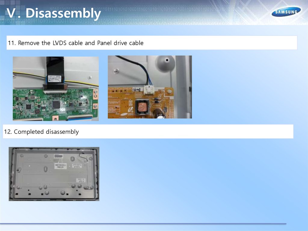
Ⅴ. Disassembly11. Remove the LVDS cable and Panel drive cable
12. Completed disassembly
54.
Ⅴ. Disassembly1.
Place monitor face down on cushioned table.
2. Remove 4 screws from the stand.
55.
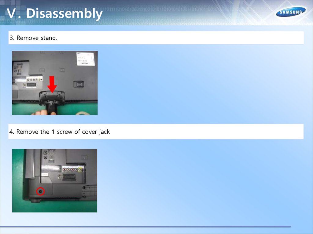
Ⅴ. Disassembly3. Remove stand.
4. Remove the 1 screw of cover jack
56.
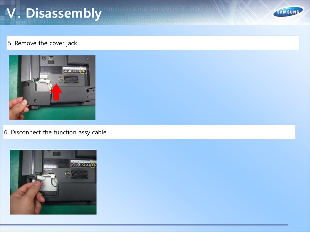
Ⅴ. Disassembly5. Remove the cover jack.
6. Disconnect the function assy cable..
57.
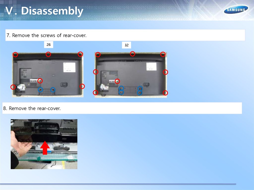
Ⅴ. Disassembly7. Remove the screws of rear-cover.
26
8. Remove the rear-cover.
32
58.
Ⅴ. Disassembly9.Remove the screws of main board and IP board and Panel.
26
10. Remove the speakers and power cables.
32
59.
Ⅴ. Disassembly11. Remove the LVDS cable and Panel drive cable
12. Completed disassembly
60.
Ⅴ. Disassembly(PTC)1. Place monitor face up on cushioned table.
2. remove the T-CON Cover
61.
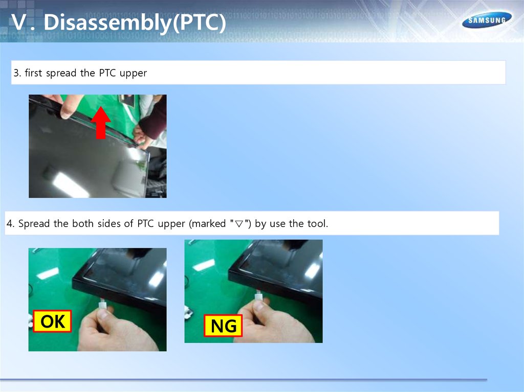
Ⅴ. Disassembly(PTC)3. first spread the PTC upper
4. Spread the both sides of PTC upper (marked "▽") by use the tool.
OK
NG
62.
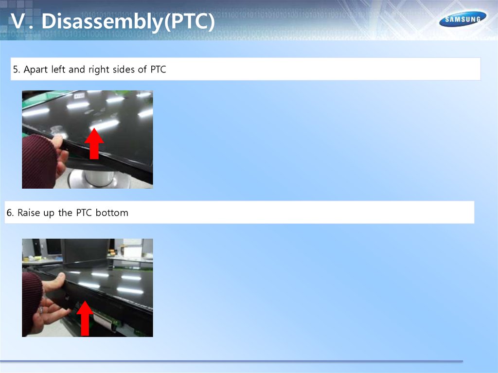
Ⅴ. Disassembly(PTC)5. Apart left and right sides of PTC
6. Raise up the PTC bottom
63.
Ⅴ. Disassembly(PTC)7. Disassembly is complete.
64.
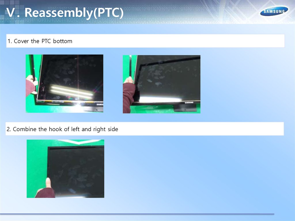
Ⅴ. Reassembly(PTC)1. Cover the PTC bottom
2. Combine the hook of left and right side
65.
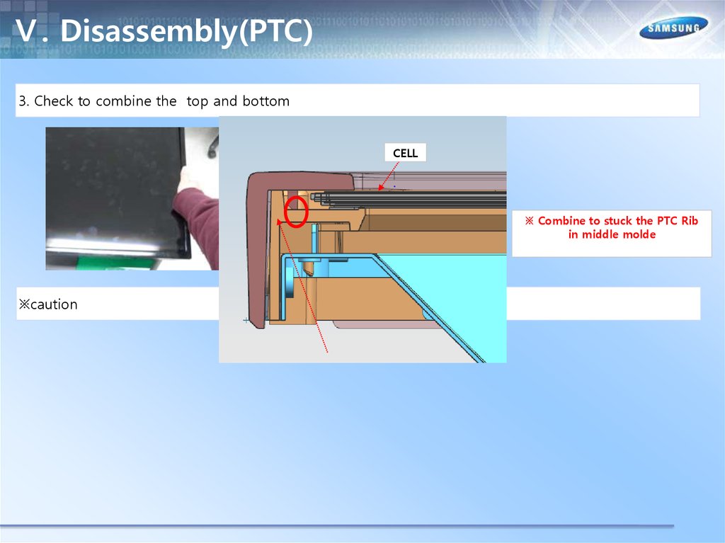
Ⅴ. Disassembly(PTC)3. Check to combine the top and bottom
CELL
※ Combine to stuck the PTC Rib
in middle molde
※caution
66.
Ⅴ. Disassembly(PTC)3. Check to combine the top and bottom
67.
Ⅴ. Disassembly(PTC)※caution
CELL
MIDDLE
MOLD
※ Combine to stuck the PTC Rib
in middle molde
68.
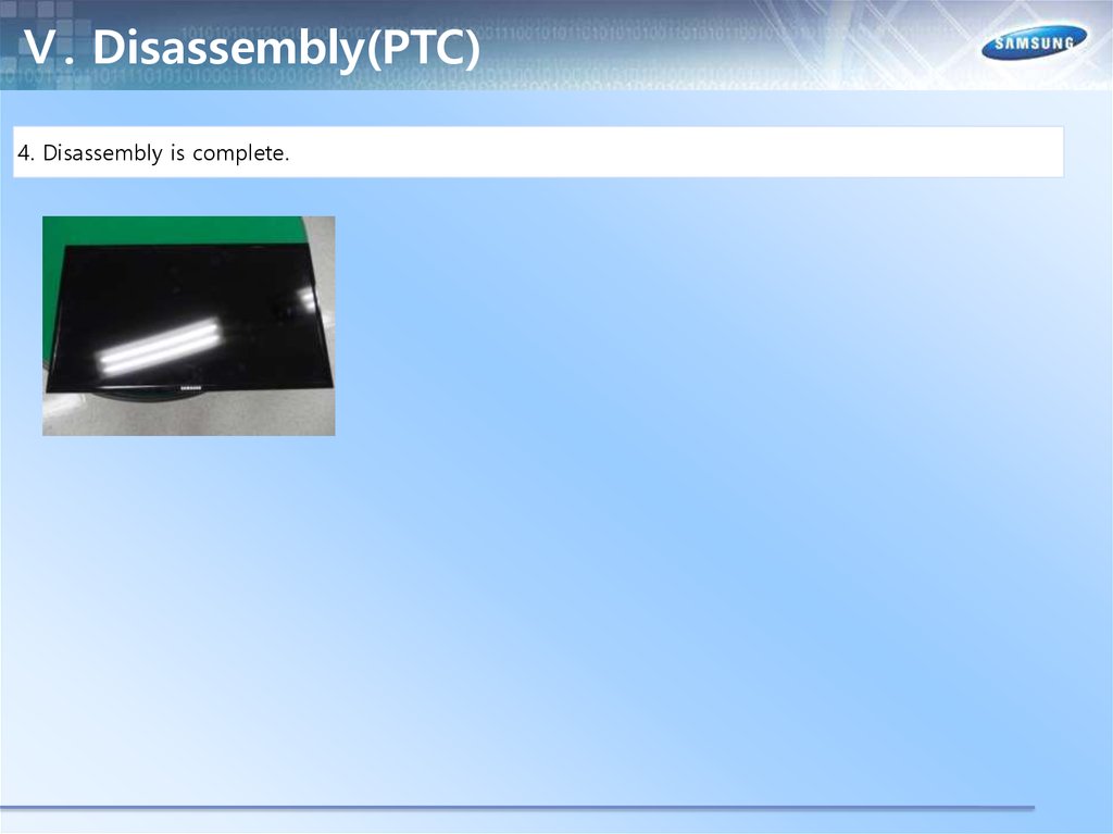
Ⅴ. Disassembly(PTC)4. Disassembly is complete.
69.
Ⅵ. Trouble ShootingCheck List for Initial operation
Main
Ass'y
Power
cable
Power
Ass'y
LVDS cable
Speake
r
70.
Ⅵ. Trouble ShootingNo power AND No Video
Power cord on
Check 'Stand-By A5.3V'
5.3V appear at BD210?
0V to 5.3V (CN201 #4)
NO
Cause : There did not supply the power from SMPS
measure : Change 14p power cable and SMPS
YES
Set On
Check 'SW_POWER'
more than 3.3V appear at CN201(#2)
0V to 3.3V↑ (CN201 #2)
NO
Cause : Main IC(X9) did not control the SW_Power
measure : Change the Main Assy
YES
Check ‘Power input of Main Ass'y’ ?
DC B13V, B5.3V appear at
CN201 #11,12,13(B13V)
CN201 #1,3 (B5.3V)?
0V to 13V (CN201 #11,12,13)
0 to 5.3V (CN201 #1,3)
NO
Cause : There did not supply the power from SMPS
measure : Change 14p power cable and SMPS
71.
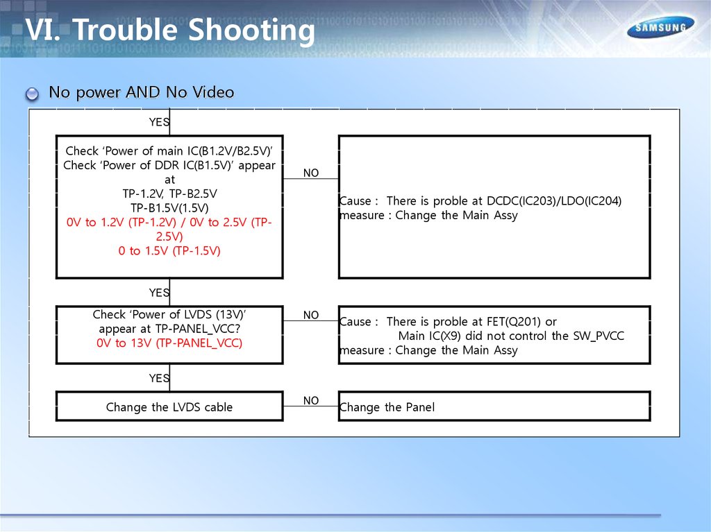
Ⅵ. Trouble ShootingNo power AND No Video
YES
Check ‘Power of main IC(B1.2V/B2.5V)’
Check ‘Power of DDR IC(B1.5V)’ appear
at
TP-1.2V, TP-B2.5V
TP-B1.5V(1.5V)
0V to 1.2V (TP-1.2V) / 0V to 2.5V (TP2.5V)
0 to 1.5V (TP-1.5V)
NO
Cause : There is proble at DCDC(IC203)/LDO(IC204)
measure : Change the Main Assy
YES
Check ‘Power of LVDS (13V)’
appear at TP-PANEL_VCC?
0V to 13V (TP-PANEL_VCC)
NO
Cause : There is proble at FET(Q201) or
Main IC(X9) did not control the SW_PVCC
measure : Change the Main Assy
NO
Change the Panel
YES
Change the LVDS cable
72.
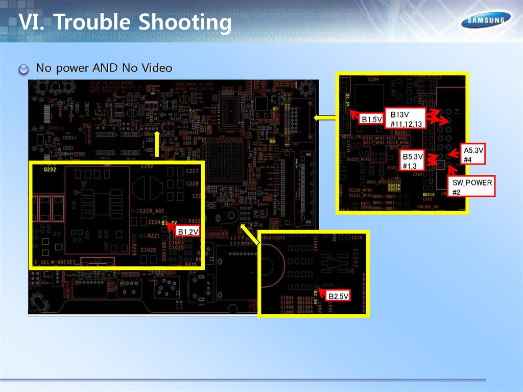
Ⅵ. Trouble ShootingNo power AND No Video
B1.5V
B13V
#11,12,13
B5.3V
#1,3
A5.3V
#4
SW_POWER
#2
B1.2V
B2.5V
73.
Ⅵ. Trouble ShootingRS232C code
74.
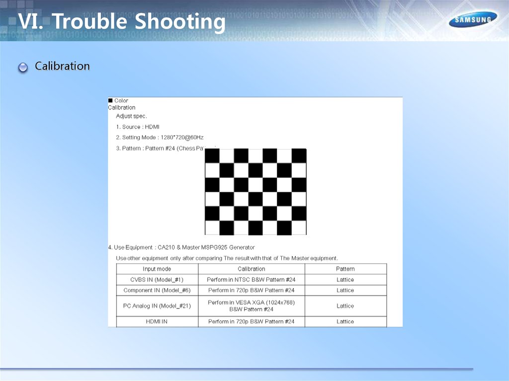
Ⅵ. Trouble ShootingCalibration
75.
Ⅵ. Trouble ShootingCalibration
76.
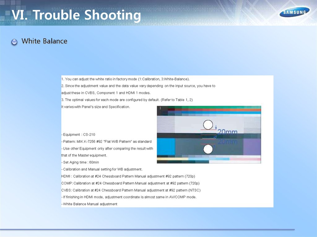
Ⅵ. Trouble ShootingWhite Balance
77.
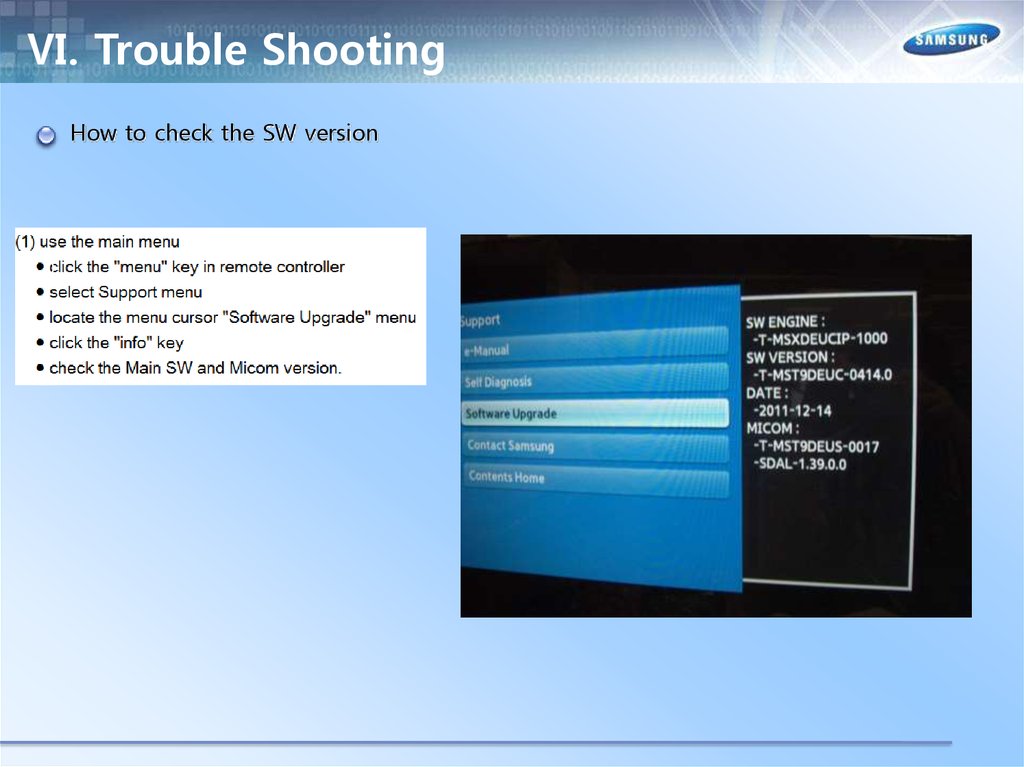
Ⅵ. Trouble ShootingHow to check the SW version
78.
Ⅵ. Trouble ShootingHow to check the SW version
(2) use the factory mode
● access the factory mode
Option
Control
SVC
Expert
ADC/WB
Advanced
T-MST0DEUC : SW Ver
T-MST0DEUS : SW Ver
EDID : SUCCESS
HDCP : SUCCESS
CALIB : AV / COMP / PC / HDMI /
OPTION:**
FactoryCS:*********
T-MSXDEUCIP-****
Onboot : ***
SDAL-****
RFS:Mstar-X9 ****
20**-**-**
79.
Ⅵ. Trouble ShootingUSB Download
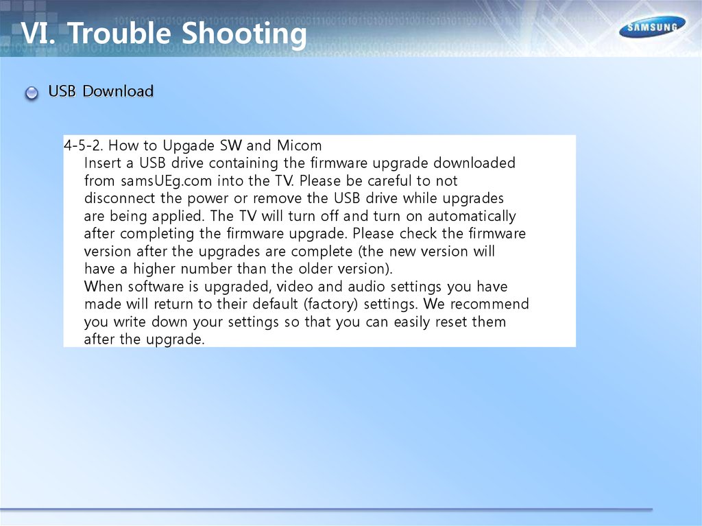
4-5-2. How to Upgade SW and Micom
Insert a USB drive containing the firmware upgrade downloaded
from samsUEg.com into the TV. Please be careful to not
disconnect the power or remove the USB drive while upgrades
are being applied. The TV will turn off and turn on automatically
after completing the firmware upgrade. Please check the firmware
version after the upgrades are complete (the new version will
have a higher number than the older version).
When software is upgraded, video and audio settings you have
made will return to their default (factory) settings. We recommend
you write down your settings so that you can easily reset them
after the upgrade.
80.
Ⅵ. Trouble ShootingUSB Download
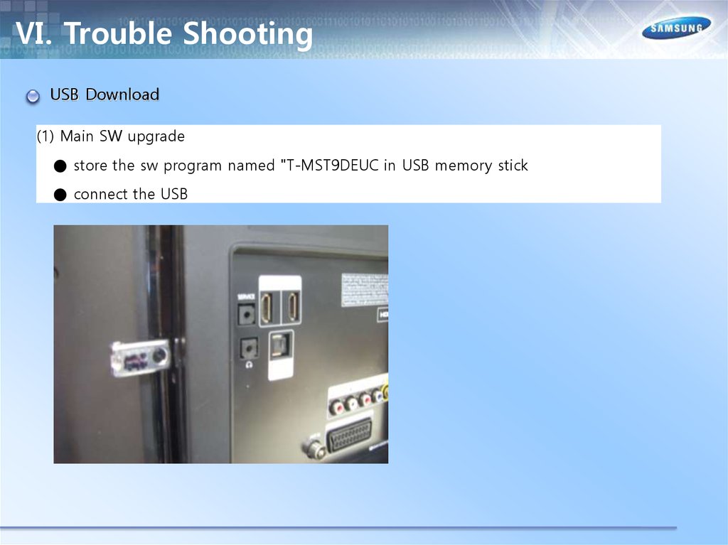
(1) Main SW upgrade
● store the sw program named "T-MST9DEUC in USB memory stick
● connect the USB
81.
Ⅵ. Trouble ShootingUSB Download
● click the "menu" key in remote controler
● select Support menu
● locate the menu cursor "Software Upgrade" menu
82.
Ⅵ. Trouble ShootingUSB Download
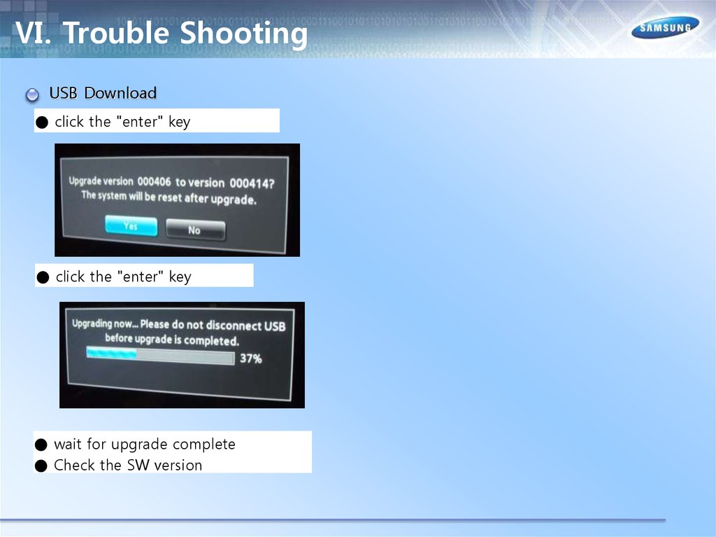
● click the "enter" key
● click the "enter" key
● wait for upgrade complete
● Check the SW version