


 Электроника
Похожие презентации:


")
LED TV. Training manual
1.
LED TVTraining manual
UE8Y
2.
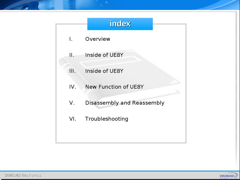
indexI.
Overview
II.
Inside of UE8Y
III.
Inside of UE8Y
IV.
New Function of UE8Y
V.
Disassembly and Reassembly
VI.
Troubleshooting
3.
UE8Y OverviewSAMSUNG
4. Spec Comparison to the Old Models
UE8Y OverviewSpec Comparison to the Old Models
Model
E8000
D8000
Display type
LED TV
LED TV
LCD panel
TFT LCD PANEL 240Hz
TFT LCD PANEL 240Hz
40.99 x10.89 x26.75 inches_with stand
40.99 x 1.17 x 23.6 inches_without
stand
42.94x11.93x28.50 inches_with stand
42.94x0.94x26.09 inches_without
stand
Design
46”
Dimensions
(W x H x D)
55”
48.53 x 12.18 x 30.99 inches_with stand
48.53 x 1.17 x 27.84 inches_without
stand
50.47x11.93x32.78 inches_with stand
50.47x0.94x30.39 inches_without
stand
Weight
46” : 27.34lbs_without stand
31.52lbs_with stand
55” : 35.71lbs_without stand
41bs_with stand
46” : 37.03lbs_without stand
42.1lbs_with stand
55” : 48.94lbs_without stand
54.01lbs_with stand
Contrast Ratio
Mega CR
Mega CR
AUTO MOTION PLUS 240HZ
O (Echo-S)
O (Napoli)
Speaker out
10W +10W
46” : 10W +10W/ 55” :15W+15W
Surround Sound
SRS Theater Sound
SRS Theater Sound
Function
3D,MOIP,Media Bridge, AllShare,Internet
TV, Built-in WiFi, Full Browser,Bluetooth,
Smart_control, Motion Contol
3D,MOIP,Media Bridge,
AllShare,Internet TV, Built-in WiFi,
Bluetooth
5.
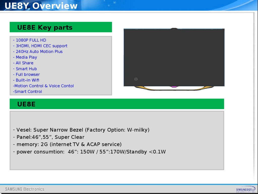
UE8Y OverviewUE8E Key parts
- 1080P FULL HD
- 3HDMI, HDMI CEC support
- 240Hz Auto Motion Plus
- Media Play
- All Share
- Smart Hub
- Full browser
- Built–in Wifi
-Motion Control & Voice Contol
-Smart Control
UE8E
- Vesel: Super Narrow Bezel (Factory Option: W-milky)
- Panel:46”,55”, Super Clear
- memory: 2G (internet TV & ACAP service)
- power consumtion: 46”: 150W / 55”:170W/Standby <0.1W
6.
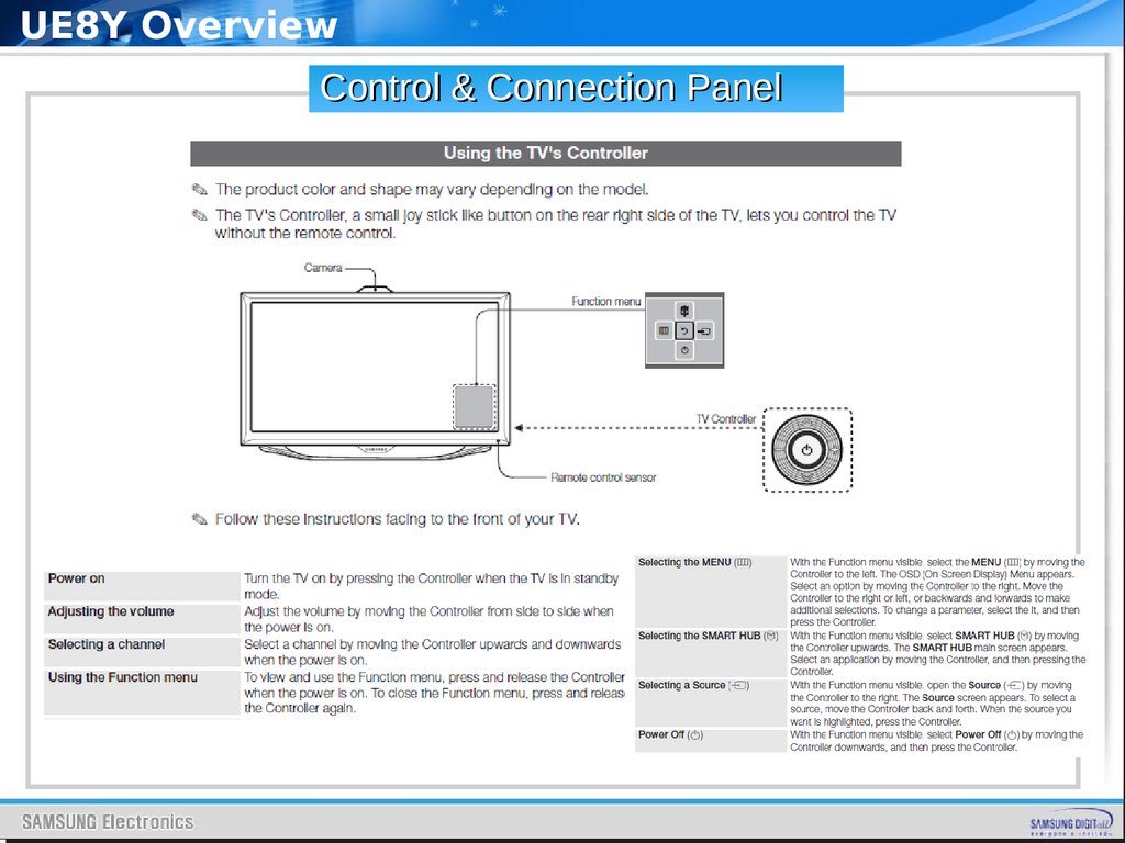
UE8Y OverviewControl & Connection Panel
7.
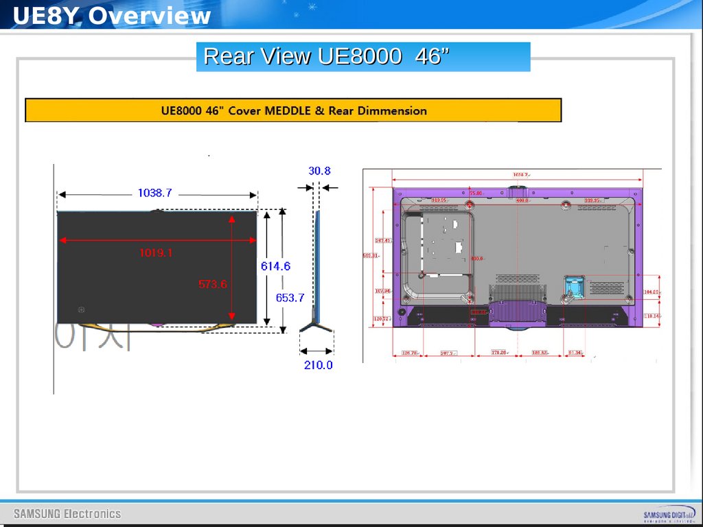
UE8Y OverviewRear View UE8000 46”
8.
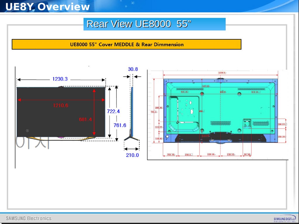
UE8Y OverviewRear View UE8000 55”
9.
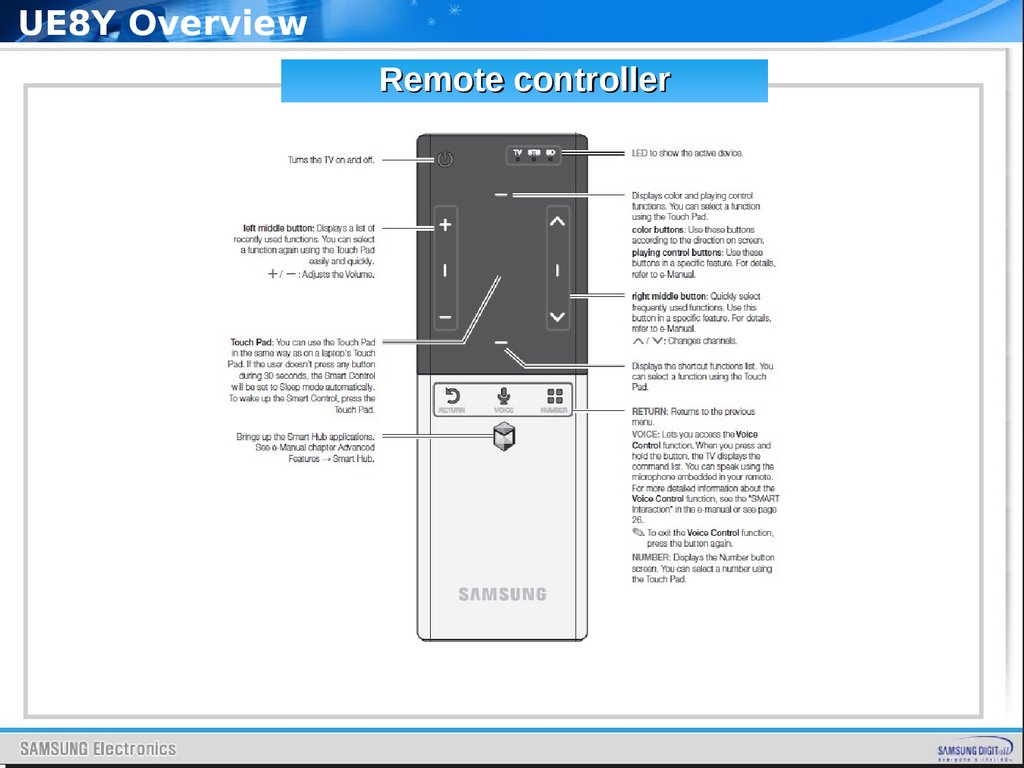
UE8Y OverviewRemote controller
10.
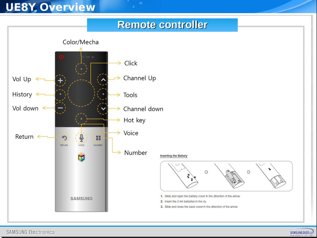
UE8Y OverviewRemote controller
11. Accessories
UE8Y OverviewAccessories
12. Accessories
UE8Y OverviewAccessories
13.
Inside of UE8YInside of UE8Y
SAMSUNG
14.
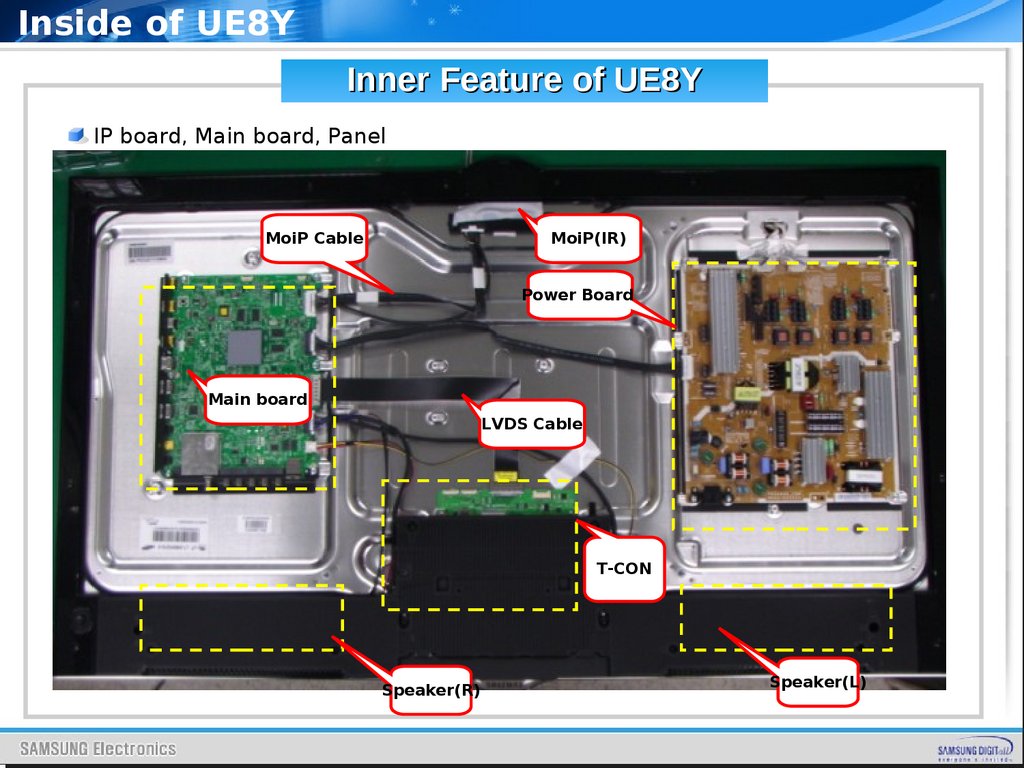
Inside of UE8YInner Feature of UE8Y
IP board, Main board, Panel
MoiP Cable
MoiP(IR)
Power Board
Main board
LVDS Cable
T-CON
Speaker(R)
Speaker(L)
15.
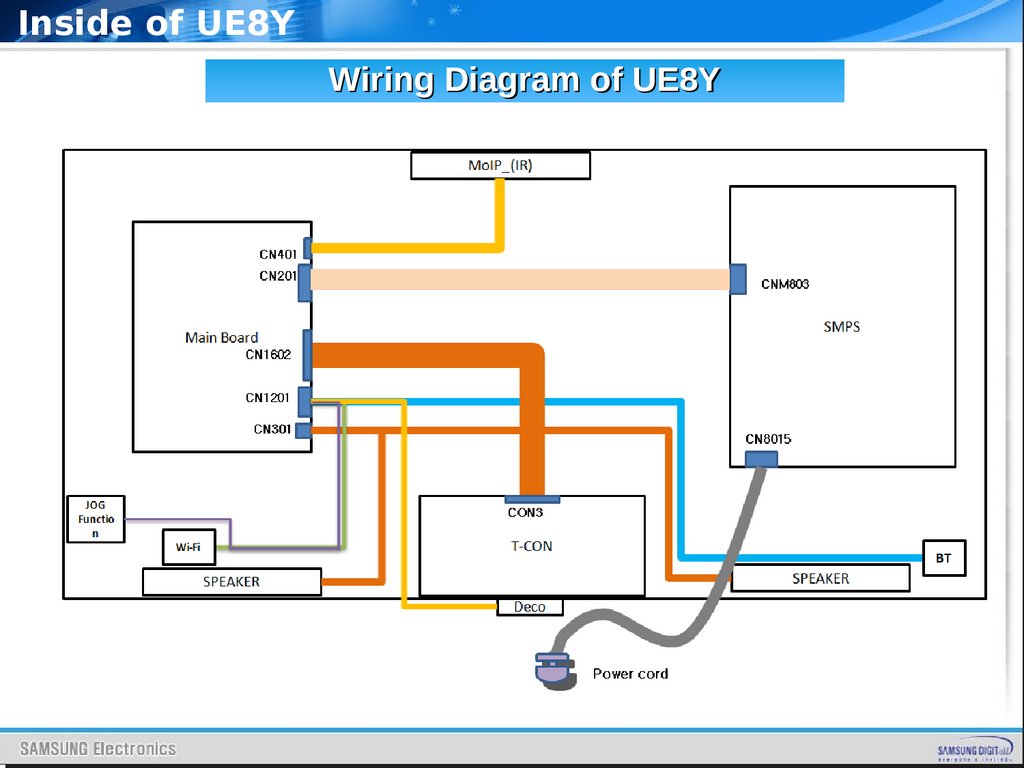
Inside of UE8YWiring Diagram of UE8Y
CNM80
3
CN8015
CON3
16.
Main BoardSAMSUNG
17.
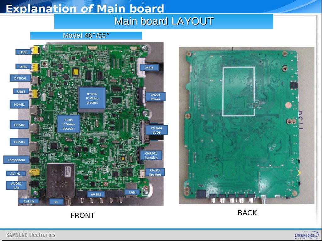
Explanation of Main boardMain board LAYOUT
Model 46”/55”
USB3
USB2
Moip
OPTICAL
USB3
IC1202
IC Video
process
HDMI1
CN201
Power
IC801
IC Video
decoder
HDMI2
Please show
bottom of board
(move photo up
or make smaller)
CN1601
LVDS
HDMI3
CN1201
Function
Component
CN301
Speaker
AV IN2
AUDIO
L/R
AV IN1
Ex-Link
LAN
RF
FRONT
BACK
18.
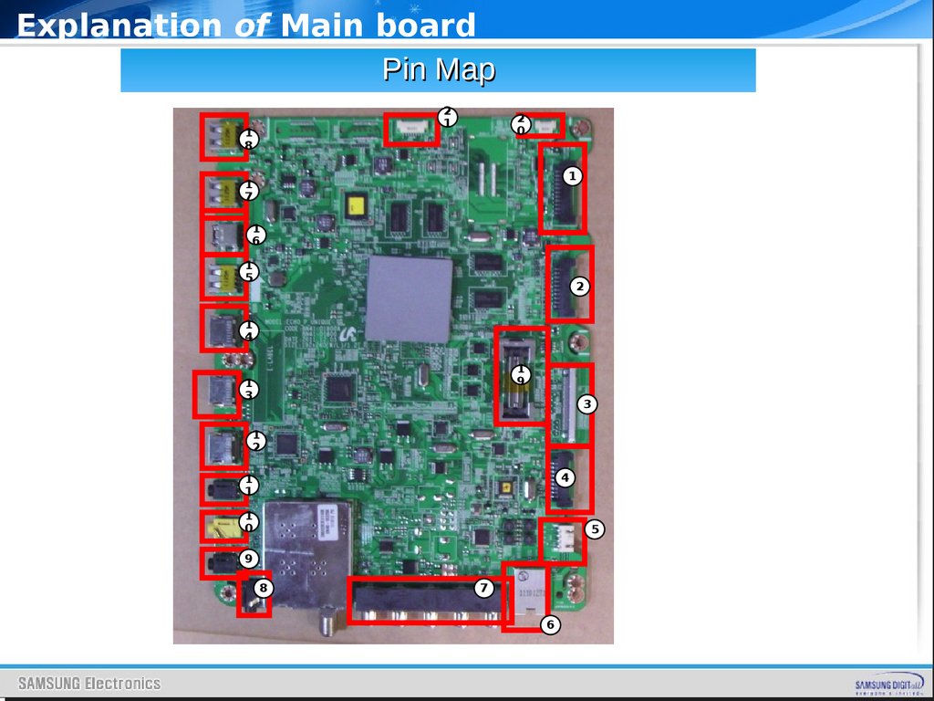
Explanation of Main boardPin Map
2
1
1
8
2
0
1
1
7
1
6
1
5
2
1
4
1
9
1
3
3
1
2
4
1
1
1
0
5
9
8
7
6
19.
Explanation of Main boardPin Map
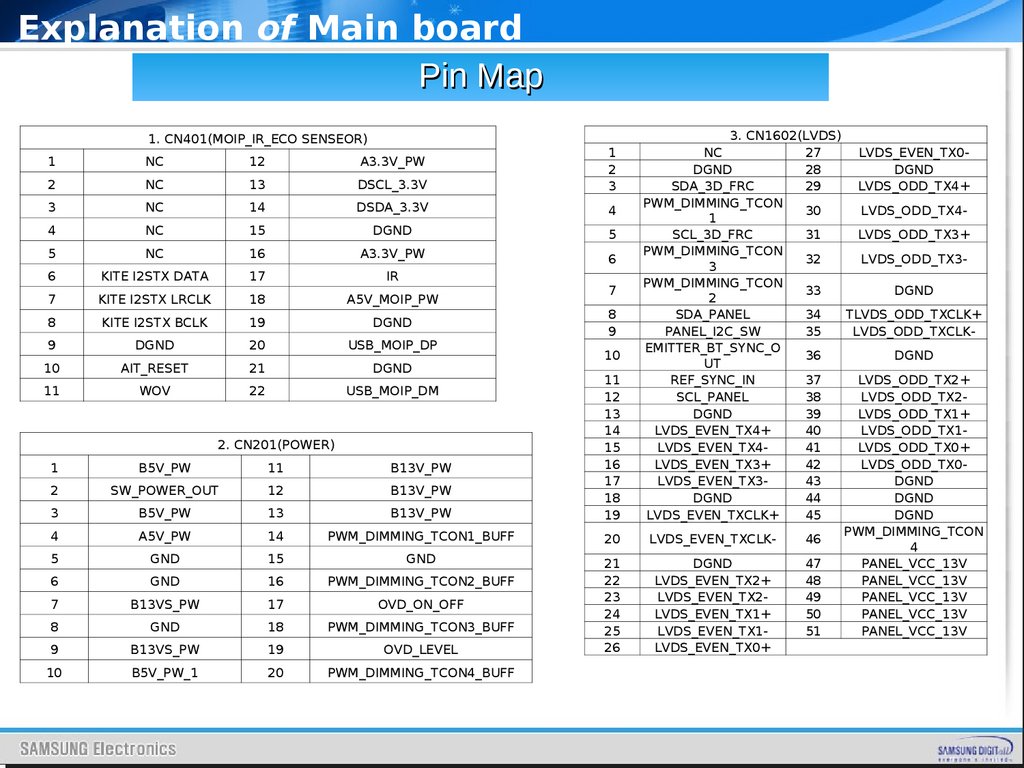
1. CN401(MOIP_IR_ECO SENSEOR)
1
NC
12
A3.3V_PW
2
NC
13
DSCL_3.3V
1
2
3
3
NC
14
DSDA_3.3V
4
4
NC
15
DGND
5
5
NC
16
A3.3V_PW
6
6
KITE I2STX DATA
17
IR
7
KITE I2STX LRCLK
18
A5V_MOIP_PW
8
KITE I2STX BCLK
19
DGND
9
DGND
20
USB_MOIP_DP
10
AIT_RESET
21
DGND
11
WOV
22
USB_MOIP_DM
1
B5V_PW
11
B13V_PW
2
SW_POWER_OUT
12
B13V_PW
3
B5V_PW
13
B13V_PW
11
12
13
14
15
16
17
18
19
4
A5V_PW
14
PWM_DIMMING_TCON1_BUFF
20
5
GND
15
GND
6
GND
16
PWM_DIMMING_TCON2_BUFF
7
B13VS_PW
17
OVD_ON_OFF
8
GND
18
PWM_DIMMING_TCON3_BUFF
9
B13VS_PW
19
OVD_LEVEL
21
22
23
24
25
26
10
B5V_PW_1
20
PWM_DIMMING_TCON4_BUFF
2. CN201(POWER)
7
8
9
10
3. CN1602(LVDS)
NC
27
LVDS_EVEN_TX0DGND
28
DGND
SDA_3D_FRC
29
LVDS_ODD_TX4+
PWM_DIMMING_TCON
30
LVDS_ODD_TX41
SCL_3D_FRC
31
LVDS_ODD_TX3+
PWM_DIMMING_TCON
32
LVDS_ODD_TX33
PWM_DIMMING_TCON
33
DGND
2
SDA_PANEL
34
TLVDS_ODD_TXCLK+
PANEL_I2C_SW
35
LVDS_ODD_TXCLKEMITTER_BT_SYNC_O
36
DGND
UT
REF_SYNC_IN
37
LVDS_ODD_TX2+
SCL_PANEL
38
LVDS_ODD_TX2DGND
39
LVDS_ODD_TX1+
LVDS_EVEN_TX4+
40
LVDS_ODD_TX1LVDS_EVEN_TX441
LVDS_ODD_TX0+
LVDS_EVEN_TX3+
42
LVDS_ODD_TX0LVDS_EVEN_TX343
DGND
DGND
44
DGND
LVDS_EVEN_TXCLK+
45
DGND
PWM_DIMMING_TCON
LVDS_EVEN_TXCLK46
4
DGND
47
PANEL_VCC_13V
LVDS_EVEN_TX2+
48
PANEL_VCC_13V
LVDS_EVEN_TX249
PANEL_VCC_13V
LVDS_EVEN_TX1+
50
PANEL_VCC_13V
LVDS_EVEN_TX151
PANEL_VCC_13V
LVDS_EVEN_TX0+
20.
Explanation of Main boardPin Map
4. CN1201(KEY FUNCTION & BLUETOOTH & WIFI)
POWER_DET
10
EMITTER_BT_SYNC_OUT
A5V_PW
11
A3.3V_PW
WAKE_BT
12
REF_SYNC_IN
USB_BT_DM
13
LDC_CNTR
KEY_INPUT1
14
NC
USB_BT_DP
15
B5V_WIFI_CI_PW
KEY_INPUT2
16
USB_WIFI_DP_HUB2
DGND
17
DGND
DGND
18
USB_WIFI_DM_HUB2
1
2
3
4
5
6
7
8
9
5. CN301(SPEAKER)
1
DGND
2
OUT_D
3
OUT_B
4
DGND
1
2
3
4
5
6
7
8
1
2
3
4
5
6
7
8
6. CN1701(LAN)
TX+
DGND
TXRX+
DGND
RXNC
LAN_GND
7. CN404(COMPONENT)
DGND
9
COMP_PR
COMP_AVI_SR_I
10
DGND
N
COMP_AVI_SL_IN 11
COMP_PB
DGND
12
IDENT_COMP
COMP_AVI_SL_IN 13
DGND
COMP_AVI_SR_I
14
COMP_Y_AV1
N
DGND
15
IDENT_AV1
COMP_PR
1
2
3
4
5
6
7
8. CN507(AV-LINK)
DGND
TDB
NC
RDB
NC
NC
AUTOSTAND_B5V
9. CN302(HEADPHONE)
1
DGND
2
HP_AUD_SL_OUT
3
HP_SUD_SR_OUT
4
IDENT_HP
5
DGND
6
HP_AUD_SL_OUT
10. CN506_UBA(CVBS)
1
DGND
2
SCL_AV2_CVBS
3
SCL_AV2_SR_IN
4
NC
5
NC
6
SCL_AV2_ID
7
SCL_AV2_SL_IN
21.
Explanation of Main boardPin Map
1
2
3
4
5
6
7
8
9
10
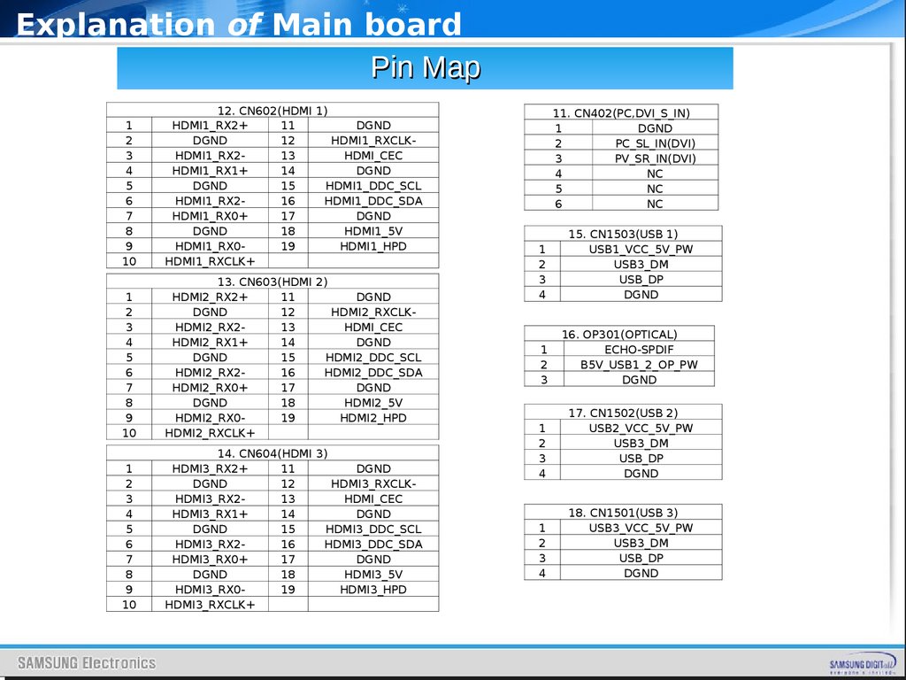
12. CN602(HDMI 1)
HDMI1_RX2+
11
DGND
DGND
12
HDMI1_RXCLKHDMI1_RX213
HDMI_CEC
HDMI1_RX1+
14
DGND
DGND
15
HDMI1_DDC_SCL
HDMI1_RX216
HDMI1_DDC_SDA
HDMI1_RX0+
17
DGND
DGND
18
HDMI1_5V
HDMI1_RX019
HDMI1_HPD
HDMI1_RXCLK+
1
2
3
4
5
6
7
8
9
10
13. CN603(HDMI 2)
HDMI2_RX2+
11
DGND
DGND
12
HDMI2_RXCLKHDMI2_RX213
HDMI_CEC
HDMI2_RX1+
14
DGND
DGND
15
HDMI2_DDC_SCL
HDMI2_RX216
HDMI2_DDC_SDA
HDMI2_RX0+
17
DGND
DGND
18
HDMI2_5V
HDMI2_RX019
HDMI2_HPD
HDMI2_RXCLK+
1
2
3
4
5
6
7
8
9
10
14. CN604(HDMI 3)
HDMI3_RX2+
11
DGND
DGND
12
HDMI3_RXCLKHDMI3_RX213
HDMI_CEC
HDMI3_RX1+
14
DGND
DGND
15
HDMI3_DDC_SCL
HDMI3_RX216
HDMI3_DDC_SDA
HDMI3_RX0+
17
DGND
DGND
18
HDMI3_5V
HDMI3_RX019
HDMI3_HPD
HDMI3_RXCLK+
11. CN402(PC,DVI_S_IN)
1
DGND
2
PC_SL_IN(DVI)
3
PV_SR_IN(DVI)
4
NC
5
NC
6
NC
1
2
3
4
15. CN1503(USB 1)
USB1_VCC_5V_PW
USB3_DM
USB_DP
DGND
1
2
3
16. OP301(OPTICAL)
ECHO-SPDIF
B5V_USB1_2_OP_PW
DGND
1
2
3
4
17. CN1502(USB 2)
USB2_VCC_5V_PW
USB3_DM
USB_DP
DGND
1
2
3
4
18. CN1501(USB 3)
USB3_VCC_5V_PW
USB3_DM
USB_DP
DGND
22.
Explanation of Main boardPin Map
1
B13V_UP_PW
21
2
B13V_UP_PW
22
3
NC
23
4
ECHO_ODD_TX0- 24
5
ECHO_ODD_TX0+ 25
6
ECHO_ODD_TX1- 26
7
ECHO_ODD_TX1+ 27
8
ECHO_ODD_TX2- 28
9
ECHO_ODD_TX2+ 29
10
DGND
30
11 ECHO_ODD_TXCLK- 31
12 ECHO_ODD_TXCLK+ 32
13
DGND
33
14 ECHO_ODD_TX3- 34
15 ECHO_ODD_TX3+ 35
16 ECHO_ODD_TX4- 36
17 ECHO_ODD_TX4+ 37
18 ECHO_EVEN_TX0- 38
19 ECHO_EVEN_TX0+ 39
20 ECHO_EVEN_TX1- 40
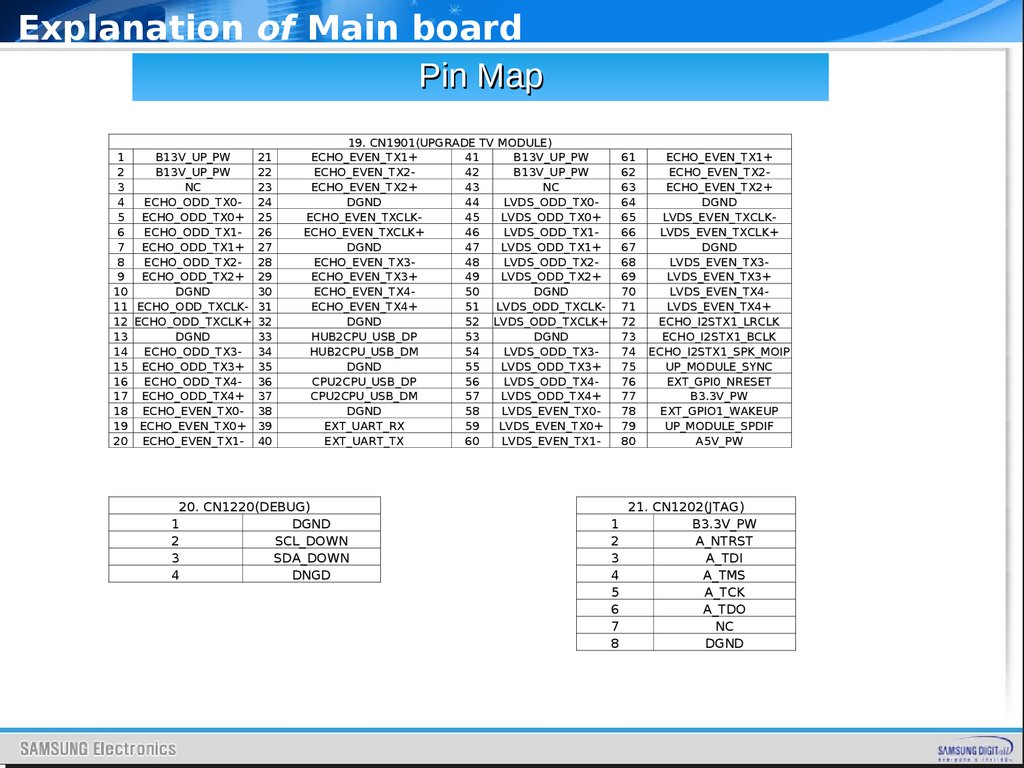
19. CN1901(UPGRADE TV MODULE)
ECHO_EVEN_TX1+
41
B13V_UP_PW
ECHO_EVEN_TX242
B13V_UP_PW
ECHO_EVEN_TX2+
43
NC
DGND
44
LVDS_ODD_TX0ECHO_EVEN_TXCLK45
LVDS_ODD_TX0+
ECHO_EVEN_TXCLK+
46
LVDS_ODD_TX1DGND
47
LVDS_ODD_TX1+
ECHO_EVEN_TX348
LVDS_ODD_TX2ECHO_EVEN_TX3+
49
LVDS_ODD_TX2+
ECHO_EVEN_TX450
DGND
ECHO_EVEN_TX4+
51
LVDS_ODD_TXCLKDGND
52 LVDS_ODD_TXCLK+
HUB2CPU_USB_DP
53
DGND
HUB2CPU_USB_DM
54
LVDS_ODD_TX3DGND
55
LVDS_ODD_TX3+
CPU2CPU_USB_DP
56
LVDS_ODD_TX4CPU2CPU_USB_DM
57
LVDS_ODD_TX4+
DGND
58
LVDS_EVEN_TX0EXT_UART_RX
59
LVDS_EVEN_TX0+
EXT_UART_TX
60
LVDS_EVEN_TX1-
20. CN1220(DEBUG)
1
DGND
2
SCL_DOWN
3
SDA_DOWN
4
DNGD
61
62
63
64
65
66
67
68
69
70
71
72
73
74
75
76
77
78
79
80
1
2
3
4
5
6
7
8
ECHO_EVEN_TX1+
ECHO_EVEN_TX2ECHO_EVEN_TX2+
DGND
LVDS_EVEN_TXCLKLVDS_EVEN_TXCLK+
DGND
LVDS_EVEN_TX3LVDS_EVEN_TX3+
LVDS_EVEN_TX4LVDS_EVEN_TX4+
ECHO_I2STX1_LRCLK
ECHO_I2STX1_BCLK
ECHO_I2STX1_SPK_MOIP
UP_MODULE_SYNC
EXT_GPI0_NRESET
B3.3V_PW
EXT_GPIO1_WAKEUP
UP_MODULE_SPDIF
A5V_PW
21. CN1202(JTAG)
B3.3V_PW
A_NTRST
A_TDI
A_TMS
A_TCK
A_TDO
NC
DGND
23.
New Funtion of UE8YSAMSUNG
24.
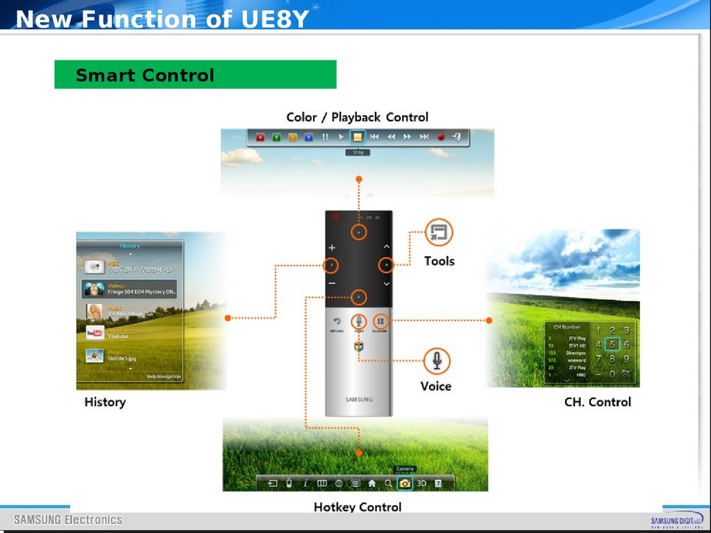
New Function of UE8YSmart Control
25.
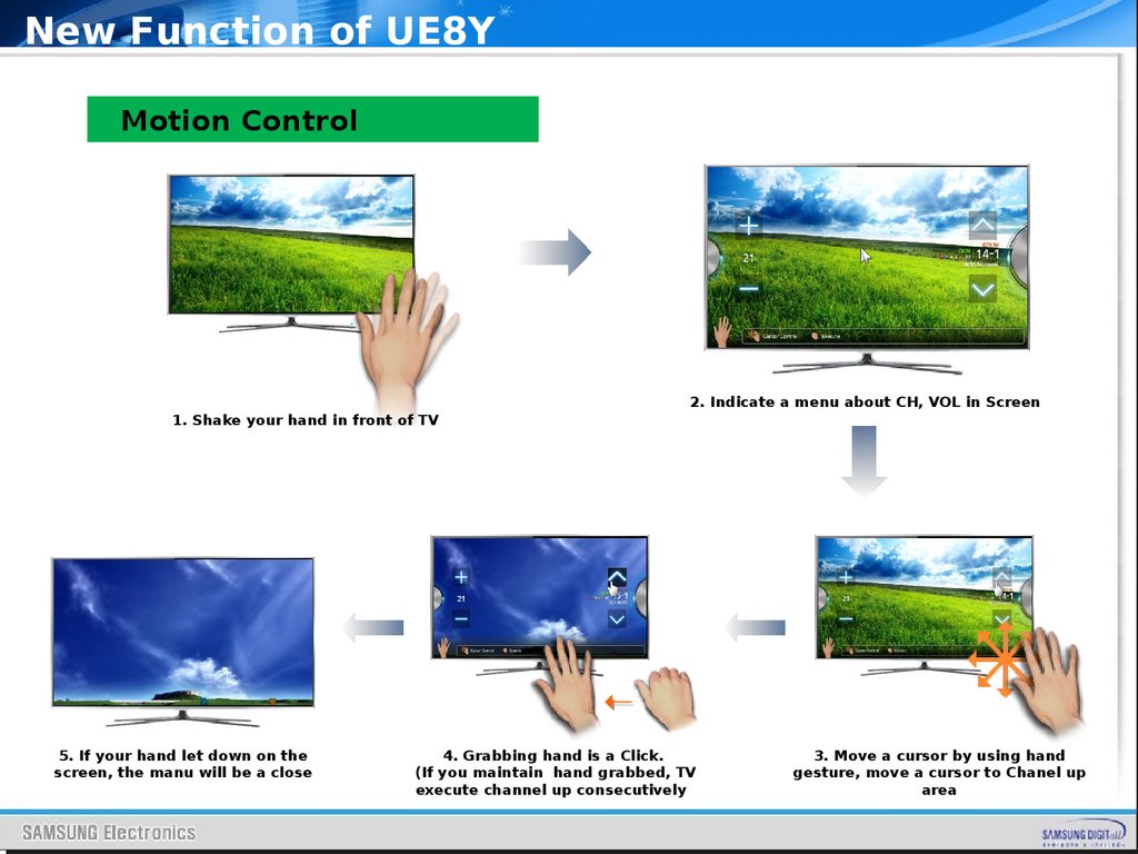
New Function of UE8YMotion Control
1. Shake your hand in front of TV
5. If your hand let down on the
screen, the manu will be a close
2. Indicate a menu about CH, VOL in Screen
4. Grabbing hand is a Click.
(If you maintain hand grabbed, TV
execute channel up consecutively
3. Move a cursor by using hand
gesture, move a cursor to Chanel up
area
26.
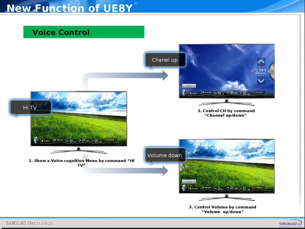
New Function of UE8YVoice Control
Chanel up
채널 올려
Hi TV
1. Show a Voice cognition Menu by command “Hi
TV”
2. Control CH by command
“Channel up/down”
Volume down
볼륨 내려
3. Control Volume by command
“Volume up/down”
27.
Disassembly and ReassemblyDisassembly
and
Reassembly
SAMSUNG
28.
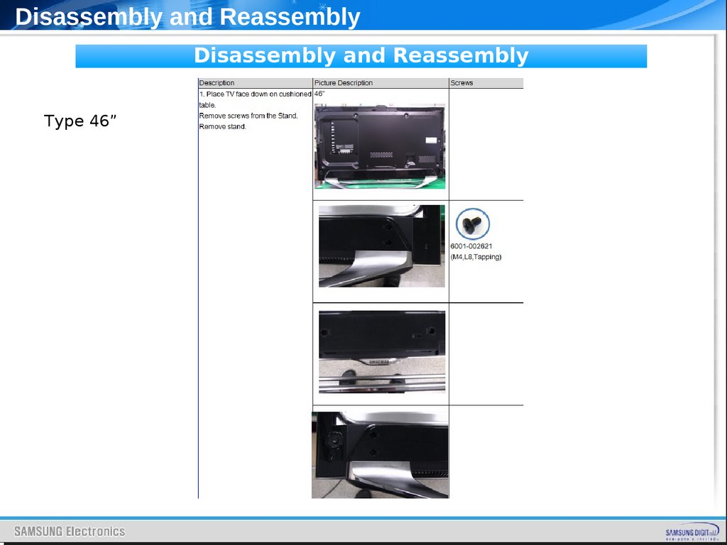
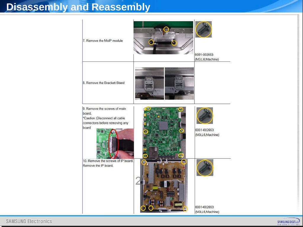
Disassembly and ReassemblyDisassembly and Reassembly
Type 46”
29.
Disassembly and Reassembly30.
Disassembly and Reassembly31.
Disassembly and Reassembly32.
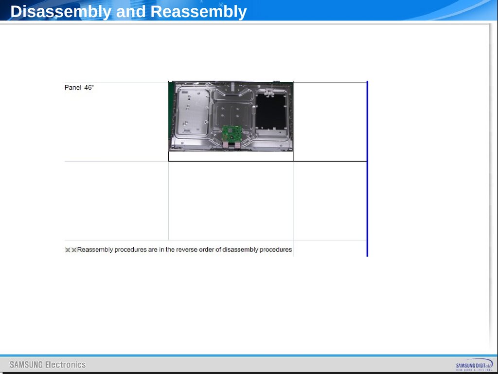
Disassembly and Reassembly33.
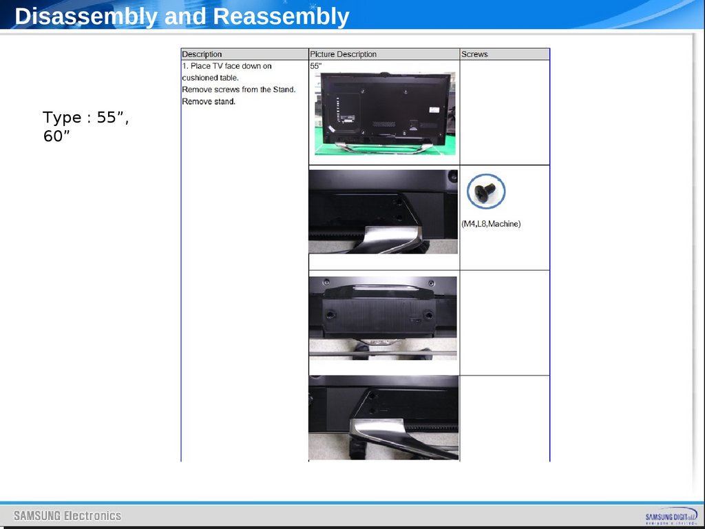
Disassembly and ReassemblyType : 55”,
60”
34.
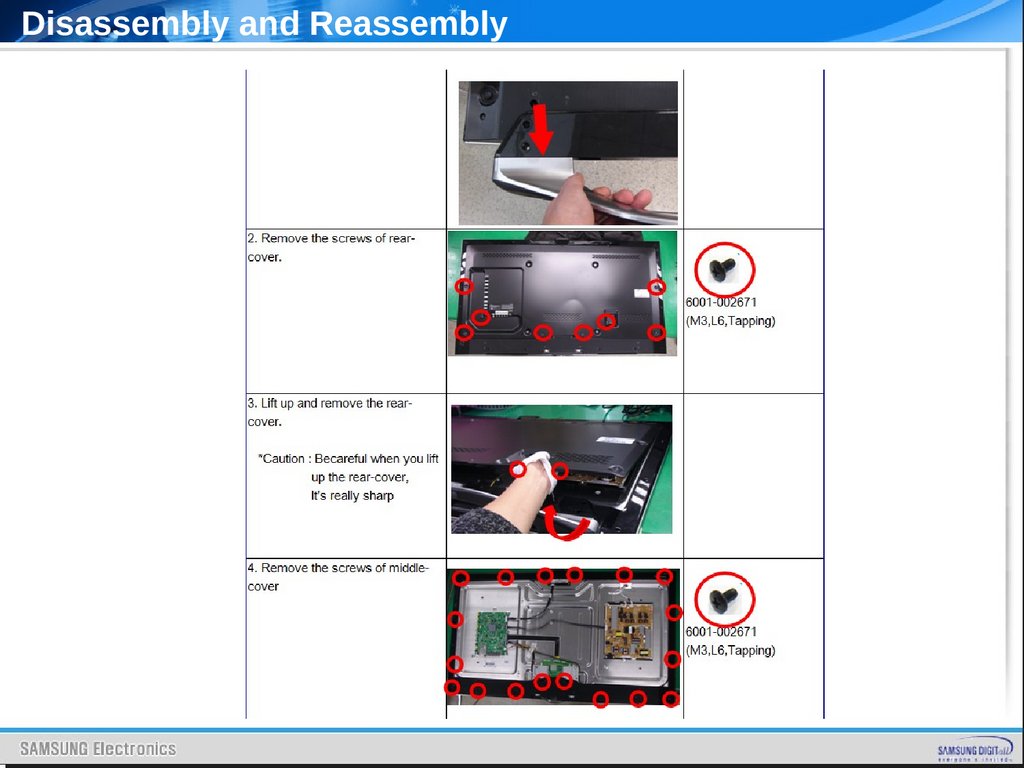
Disassembly and Reassembly35.
Disassembly and Reassembly36.
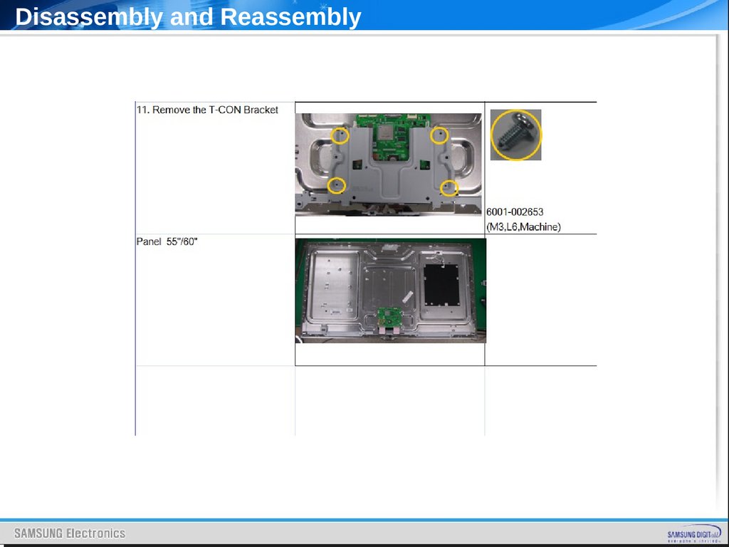
Disassembly and Reassembly37.
Disassembly and Reassembly38.
TroubleshootingSAMSUNG
39.
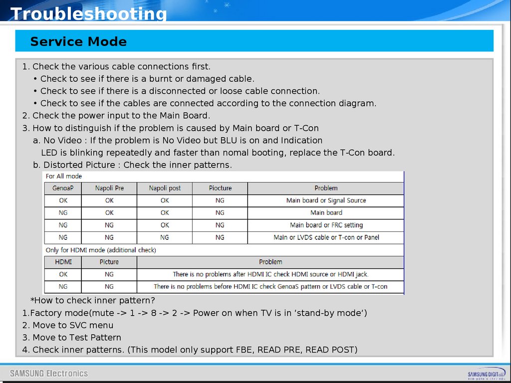
TroubleshootingService Mode
1. Check the various cable connections first.
• Check to see if there is a burnt or damaged cable.
• Check to see if there is a disconnected or loose cable connection.
• Check to see if the cables are connected according to the connection diagram.
2. Check the power input to the Main Board.
3. How to distinguish if the problem is caused by Main board or T-Con
a. No Video : If the problem is No Video but BLU is on and Indication
LED is blinking repeatedly and faster than nomal booting, replace the T-Con board.
b. Distorted Picture : Check the inner patterns.
*How to check inner pattern?
1.Factory mode(mute -> 1 -> 8 -> 2 -> Power on when TV is in ‘stand-by mode’)
2. Move to SVC menu
3. Move to Test Pattern
4. Check inner patterns. (This model only support FBE, READ PRE, READ POST)
40.
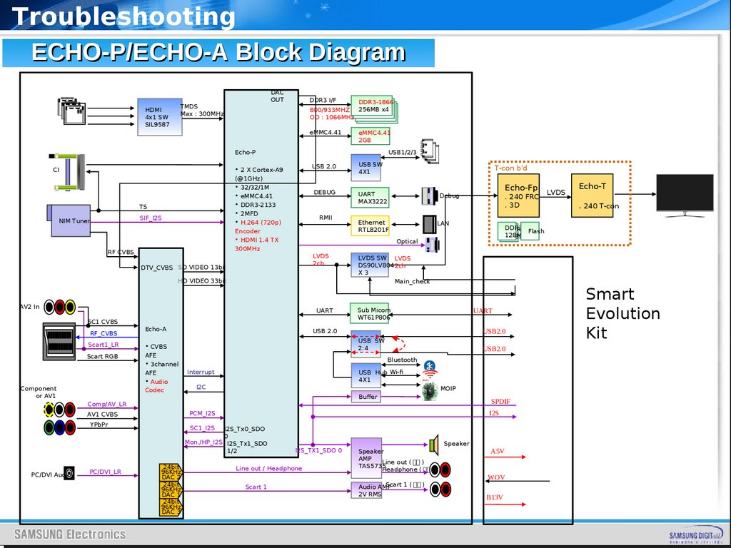
TroubleshootingECHO-P/ECHO-A Block Diagram
DAC
OUT
TMDS
Max : 300MHz
HDMI
4x1 SW
SIL9587
DDR3 I/F
DDR3-1866
800/933MHZ 256MB x4
OD : 1066MHz
eMMC4.41
eMMC4.41
2GB
USB 2.0
USB SW
4X1
DEBUG
UART
MAX3222
Debug
Ethernet
RTL8201F
LAN
Echo-P
USB1/2/3
• 2 X Cortex-A9
CI
(@1GHz)
• 32/32/1M
• eMMC4.41
• DDR3-2133
• 2MFD
• H.264 (720p)
Encoder
• HDMI 1.4 TX
300MHz
TS
SIF_I2S
NIM Tuner
RF CVBS
RMII
LVDS
2ch
LVDS SW LVDS
DS90LV804 2ch
X3
Main_check
UART
Sub Micom
WT61P806
HD VIDEO 33bit
AV2 In
RF_CVBS
Echo-A
Scart1_LR
• CVBS
Scart RGB
AFE
• 3channel
AFE
• Audio
Codec
Component
or AV1
PC/DVI Audio
PC/DVI_LR
USB2.0
Bluetooth
USB Hub Wi-fi
4X1
Interrupt
I2C
IIC
MOIP
Buffer
SPDIF
I2S
SC1_I2S
I2S_Tx0_SDO
0
Mon./HP_I2S I2S_Tx1_SDO
1/2
24bit
96KHz
DAC 2
24bit
96KHz
DAC 1
24bit
96KHz
DAC 3
I2S_TX1_SDO 0
Line out / Headphone
Scart 1
Speaker
AMP
Line out ( 미주 )
TAS5735
Headphone ( 구주 )
Scart 1 ( 구주 )
Audio AMP
2V RMS
Speaker
LVDS
Echo-T
. 240 T-con
DDR3
DDR3 Flash
128MB
128MB
USB2.0
USB SW
2:4
PCM_I2S
YPbPr
. 240 FRC
. 3D
UART
USB 2.0
Comp/AV_LR
AV1 CVBS
Echo-Fp
Optical
DTV_CVBS SD VIDEO 13bit
SC1 CVBS
T-con b’d
A5V
WOV
B13V
Smart
Evolution
Kit
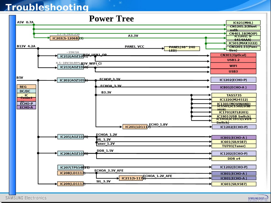
41.
TroubleshootingA5V 0.7A
Power Tree
1.7~6.5V/0.25A
A3.3V
IC203(S-1206B33)
B13V 4.2A
PANEL_VCC
~35V/1A
PANEL(46” 240
LED)
B5V_USB1_OP
IC212(AOZ1051)
IC621(MHL)
CN1201.2(Bluet
ooth
CN401.18(MOIP)
IC1201( S6414AAA)
IC501(MAX3222)
CN1201.11(Func
tion)
CN301(Optical)
USB1.2
4.5~18V/3A/89% B5V_WIFI_CI
WIFI
IC213(AOZ1051)
USB3
B5V
IC202(AOZ1051)
ECHOP_3,3V
IC1202(ECHO-P)
ECHOA_3.3V
REG
DC/DC
IC
Conect
or
ECHO-P
ECHO-A
IC801(ECHO-A )
B3.3V
ECHO_1.8V
IC201(LD1117)
IC205(AOZ1051)
IC206(AOZ1051)
ECHOA_1.2V
TAS5735
IC1220(M24512)
IC1301(MOVINAND)
IC1501,IC1502(USB
HUB)
IC1701(RTL8201)
IC1901(USB Switch)
IC1910,IC1911(LVDS
Switch)
IC1202(ECHO-P)
IC801(ECHO-A )
IC601(SIL9587)
TU701(Tuner)
SIL_1.2V
Tuner_1.2V
DDR_1.5V
IC1202(ECHO-P)
DDR x4
IC207(TPS54821)
IC208(LD1117)
IC209(LD1117)
ECHOA_3.3V_AFE
SIL_3.3V
ECHOA_1.2V_AFE
IC211(S-1172)
IC1202(ECHO-P)
IC801(ECHO-A )
IC801(ECHO-A )
IC601(SIL9587)
42.
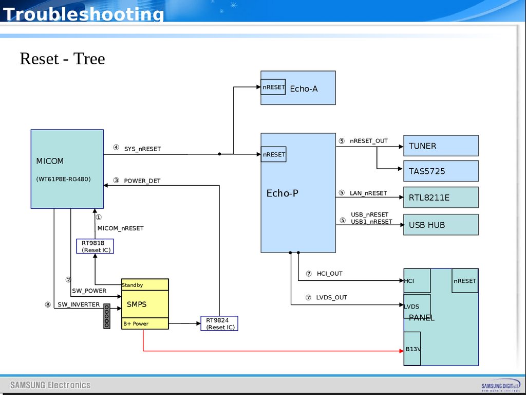
TroubleshootingReset - Tree
nRESET
⑤ nRESET_OUT
④ SYS_nRESET
nRESET
MICOM
(WT61P8E-RG480)
Echo-A
TUNER
TAS5725
③ POWER_DET
Echo-P
⑤ LAN_nRESET
RTL8211E
USB_nRESET
①
⑤ USB1_nRESET
MICOM_nRESET
USB HUB
RT9818
(Reset IC)
⑦ HCI_OUT
②
SW_POWER
⑧
SW_INVERTER
Standby
⑦ LVDS_OUT
SMPS
B+ Power
HCI
LVDS
RT9824
(Reset IC)
PANEL
B13V
nRESET
43.
TroubleshootingCheck List for Initial operation
-. AC Power Cord connected to the TV and the wall receptacle.
-. Standby Power/IR Indicator LED is turned On.
-. If Power/IR Indicator is not on check 20p power cable is connected
and
for correct Standby Voltage from SMPS to Main. Also check Jog
Function Cable.
-. Power turned On with Jog Function or Remote.
-. Power on command from main Board to SMPS.
-. Power/IR Indicator Flashes.
-. Panel Back Lights are turned On.
-. If no Backlights, unplug AC Power Cord, unplug 20 pin connector to
SMPS, plug in AC Power Cord, Back light should come on. Check
Main Board operation for error.
-. Power/IR Indicator goes off.
-. Picture or banner is displayed
* If nothing is displayed , check the LVDS cable
44.
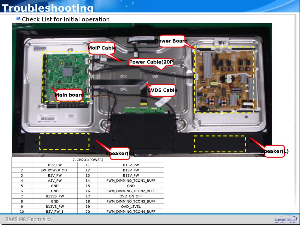
TroubleshootingCheck List for Initial operation
Power Board
MoiP Cable
Power Cable(20P
LVDS Cable
Main board
Speaker(R)
2. CN201(POWER)
1
B5V_PW
11
B13V_PW
2
SW_POWER_OUT
12
B13V_PW
3
B5V_PW
13
B13V_PW
4
A5V_PW
14
PWM_DIMMING_TCON1_BUFF
5
GND
15
GND
6
GND
16
PWM_DIMMING_TCON2_BUFF
7
B13VS_PW
17
OVD_ON_OFF
8
GND
18
PWM_DIMMING_TCON3_BUFF
9
B13VS_PW
19
OVD_LEVEL
10
B5V_PW_1
20
PWM_DIMMING_TCON4_BUFF
Speaker(L)
45.
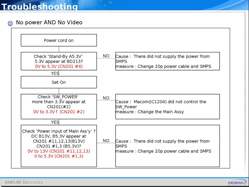
TroubleshootingNo power AND No Video
Power cord on
Check 'Stand-By A5.3V'
5.3V appear at BD213?
0V to 5.3V (CN201 #4)
NO
Cause : There did not supply the power from
SMPS
measure : Change 20p power cable and SMPS
YES
Set On
Check 'SW_POWER'
more than 3.3V appear at
CN201(#2)
0V to 3.3V↑ (CN201 #2)
NO
Cause : Macom(IC1204) did not control the
SW_Power
measure : Change the Main Assy
YES
Check ‘Power input of Main Ass'y’ ?
DC B13V, B5.3V appear at
CN201 #11,12,13(B13V)
CN201 #1,3 (B5.3V)?
0V to 13V (CN201 #11,12,13)
0 to 5.3V (CN201 #1,3)
NO
Cause : There did not supply the power from
SMPS
measure : Change 20p power cable and SMPS
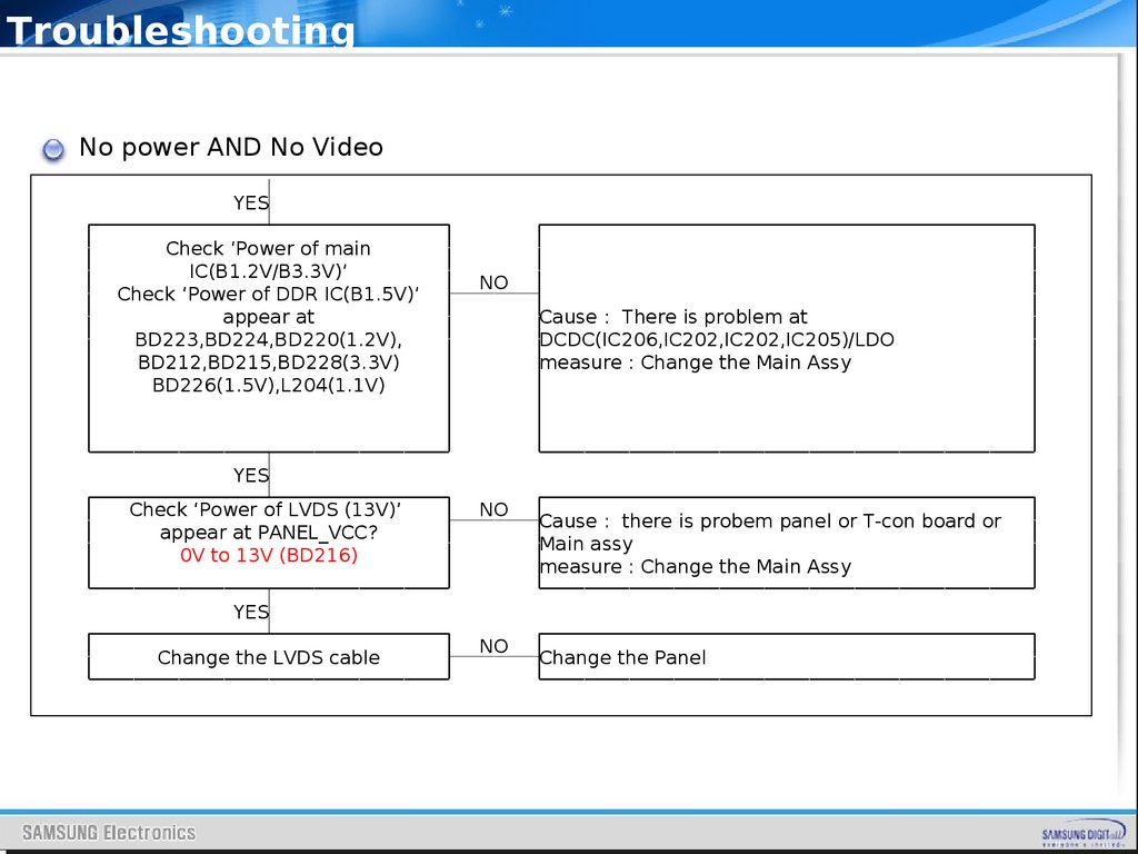
46.
TroubleshootingNo power AND No Video
YES
Check ‘Power of main
IC(B1.2V/B3.3V)’
Check ‘Power of DDR IC(B1.5V)’
appear at
BD223,BD224,BD220(1.2V),
BD212,BD215,BD228(3.3V)
BD226(1.5V),L204(1.1V)
NO
Cause : There is problem at
DCDC(IC206,IC202,IC202,IC205)/LDO
measure : Change the Main Assy
YES
Check ‘Power of LVDS (13V)’
appear at PANEL_VCC?
0V to 13V (BD216)
NO
Cause : there is probem panel or T-con board or
Main assy
measure : Change the Main Assy
YES
Change the LVDS cable
NO
Change the Panel
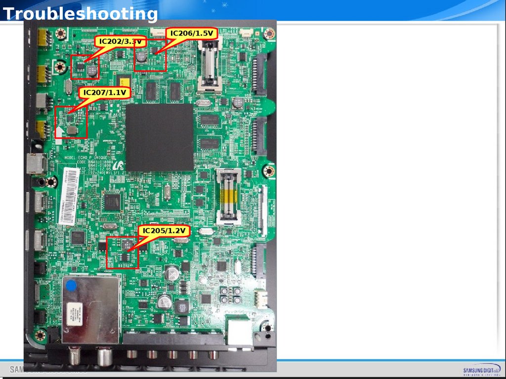
47.
TroubleshootingIC202/3.3V
IC206/1.5V
IC207/1.1V
IC205/1.2V
48.
49.
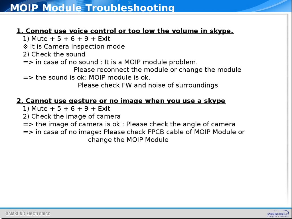
MOIP Module Troubleshooting1. Connot use voice control or too low the volume in skype.
1) Mute + 5 + 6 + 9 + Exit
※ It is Camera inspection mode
2) Check the sound
=> in case of no sound : It is a MOIP module problem.
Please reconnect the module or change the module
=> the sound is ok: MOIP module is ok.
Please check FW and noise of surroundings
2. Cannot use gesture or no image when you use a skype
1) Mute + 5 + 6 + 9 + Exit
2) Check the image of camera
=> the image of camera is ok : Please check the angle of camera
=> in case of no image: Please check FPCB cable of MOIP Module or
change the MOIP Module
50.
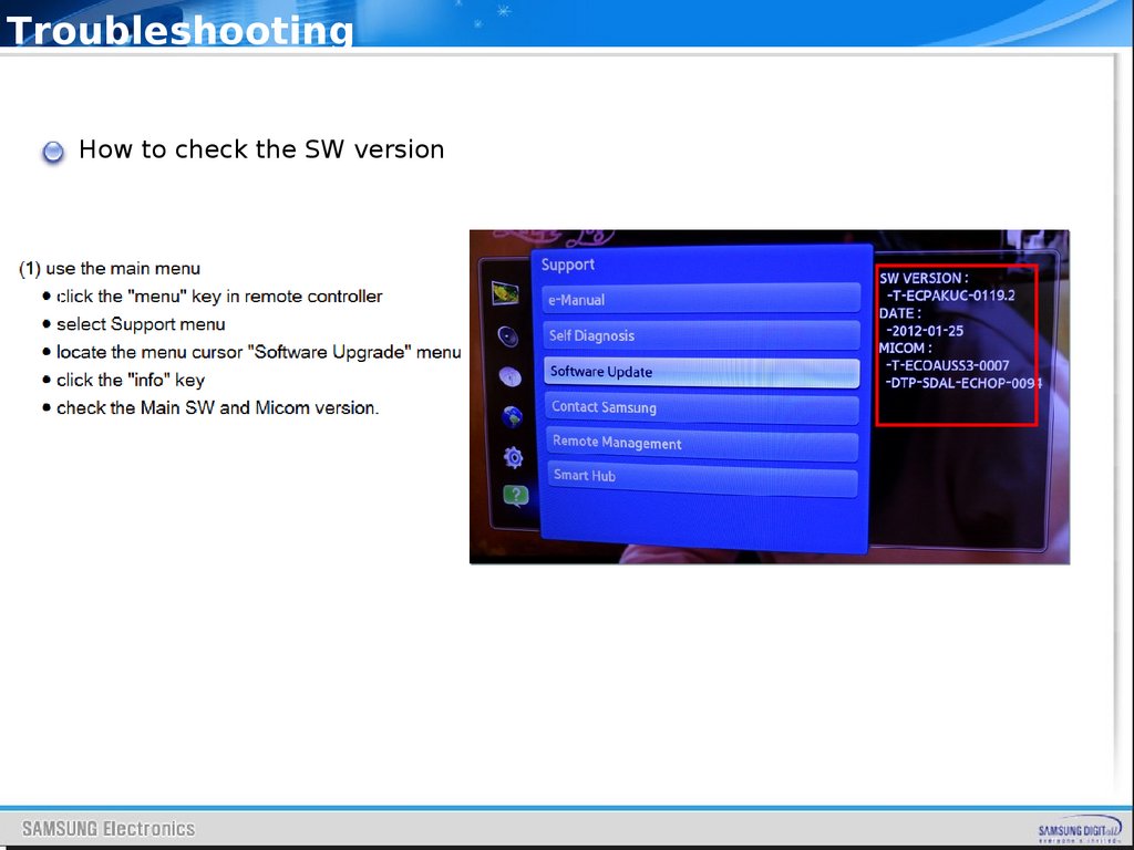
TroubleshootingHow to check the SW version
51.
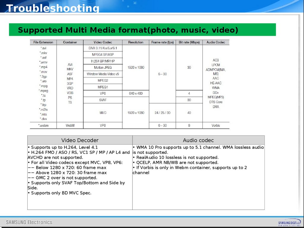
TroubleshootingSupported Multi Media format(photo, music, video)
Video Decoder
Audio codec
• Supports up to H.264, Level 4.1
• WMA 10 Pro supports up to 5.1 channel. WMA lossless audio
• H.264 FMO / ASO / RS, VC1 SP / MP / AP L4 and is not supported.
AVCHD are not supported.
• RealAudio 10 lossless is not supported.
• For all Video codecs except MVC, VP8, VP6:
• QCELP, AMR NB/WB are not supported.
−− Below 1280 x 720: 60 frame max
• If Vorbis is only in Webm container, supports up to 2
−− Above 1280 x 720: 30 frame max
channel
−− GMC 2 over is not supported.
• Supports only SVAF Top/Bottom and Side by
Side.
• Supports only BD MVC Spec.
52.
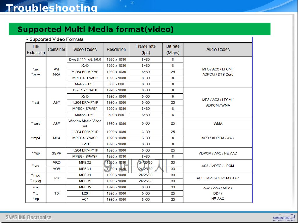
TroubleshootingSupported Multi Media format(video)
53.
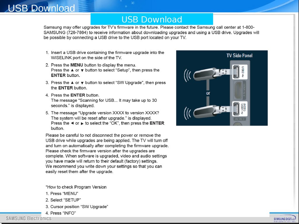
USB DownloadUSB Download