


 Интернет
Похожие презентации:


")


Basic device configuration switching, routing and wireless
1.
Module 1: Basic DeviceConfiguration
Switching, Routing and Wireless
Essentials v7.0 (SRWE)
2.
Module ObjectivesModule Title: Basic Device Configuration
Module Objective: Configure devices using security best practices.
Topic Title
Topic Objective
Configure a Switch with Initial
Settings
Configure initial settings on a Cisco switch.
Configure Switch Ports
Configure switch ports to meet network requirements.
Secure Remote Access
Configure secure management access on a switch.
Basic Router Configuration
Configure basic settings on a router to route between
two directly-connected networks, using CLI.
Verify Directly Connected Networks
Verify connectivity between two networks that are
directly connected to a router.
© 2016 Cisco and/or its affiliates. All rights reserved. Cisco Confidential
2
3.
1.1 Configure a Switch withInitial Settings
© 2016 Cisco and/or its affiliates. All rights reserved. Cisco Confidential
3
4.
Configure a Switch with Initial SettingsSwitch Boot Sequence
After a Cisco switch is powered on, it goes through the following five-step boot
sequence:
Step 1: First, the switch loads a power-on self-test (POST) program stored in ROM.
POST checks the CPU subsystem. It tests the CPU, DRAM, and the portion of the flash
device that makes up the flash file system.
Step 2: Next, the switch loads the boot loader software. The boot loader is a small
program stored in ROM that is run immediately after POST successfully completes.
Step 3: The boot loader performs low-level CPU initialization. It initializes the CPU
registers, which control where physical memory is mapped, the quantity of memory, and
its speed.
Step 4: The boot loader initializes the flash file system on the system board.
Step 5: Finally, the boot loader locates and loads a default IOS operating system
software image into memory and gives control of the switch over to the IOS.
© 2016 Cisco and/or its affiliates. All rights reserved. Cisco Confidential
4
5.
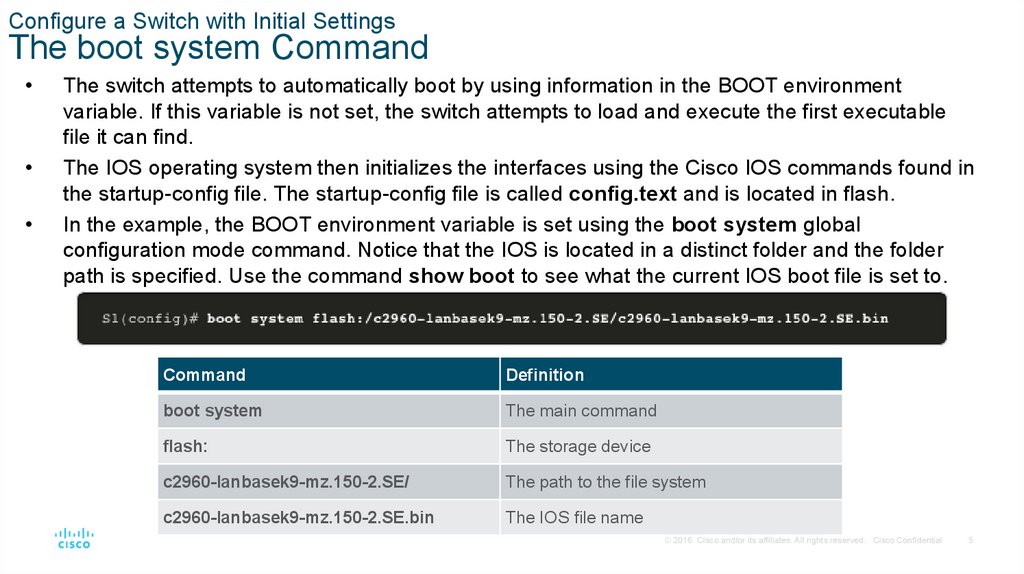
Configure a Switch with Initial SettingsThe boot system Command
The switch attempts to automatically boot by using information in the BOOT environment
variable. If this variable is not set, the switch attempts to load and execute the first executable
file it can find.
The IOS operating system then initializes the interfaces using the Cisco IOS commands found in
the startup-config file. The startup-config file is called config.text and is located in flash.
In the example, the BOOT environment variable is set using the boot system global
configuration mode command. Notice that the IOS is located in a distinct folder and the folder
path is specified. Use the command show boot to see what the current IOS boot file is set to.
Command
Definition
boot system
The main command
flash:
The storage device
c2960-lanbasek9-mz.150-2.SE/
The path to the file system
c2960-lanbasek9-mz.150-2.SE.bin
The IOS file name
© 2016 Cisco and/or its affiliates. All rights reserved. Cisco Confidential
5
6.
Configure a Switch with Initial SettingsSwitch LED Indicators
System LED (SYST): Shows whether the system is receiving power and
functioning properly.
Redundant Power Supply LED (RPS): Shows the RPS status.
Port Status LED (STAT): When green, indicates port status mode is
selected, which is the default. Port status can then be understood by the
light associated with each port.
Port Duplex LED (DUPLX): When green, indicates port duplex mode is
selected. Port duplex can then be understood by the light associated with
each port.
Port Speed LED (SPEED): When green, indicates port speed mode is
selected. Port speed can then be understood by the light associated with
each port.
Power over Ethernet LED (PoE): Present if the switch supports PoE.
Indicates the PoE status of ports on the switch.
The Mode button is used to move between the different modes – STAT,
DUPLX, SPEED, and PoE
© 2016 Cisco and/or its affiliates. All rights reserved. Cisco Confidential
6
7.
Configure a Switch with Initial SettingsSwitch LED Indicators (Cont.)
Off
Green
Blinking Green
Amber
Blinking Amber
Alternating
Green/Amber
RPS
Off/No RPS
RPS ready
RPS up but not
available
RPS standby or
fault
Internal PS failed,
RPS providing
power
N/A
PoE
Not
selected,
no issues
Selected
N/A
N/A
Not selected, port
issues present
N/A
When the named mode is selected, the light associated with each physical port indicates:
STAT
No link or
shutdown
Link Up
Activity
Port blocked
preventing loop
Port blocked
preventing loop
Link fault
DUPLEX
Half-duplex
Full-duplex
N/A
N/A
N/A
N/A
SPEED
10Mbps
100Mbps
1000Mbps
N/A
N/A
N/A
PoE
PoE off
PoE on
N/A
PoE disabled
PoE off due to
fault
PoE denied (over
budget)
© 2016 Cisco and/or its affiliates. All rights reserved. Cisco Confidential
7
8.
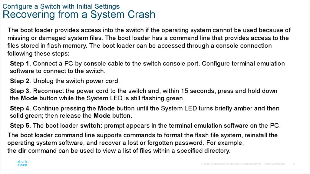
Configure a Switch with Initial SettingsRecovering from a System Crash
The boot loader provides access into the switch if the operating system cannot be used because of
missing or damaged system files. The boot loader has a command line that provides access to the
files stored in flash memory. The boot loader can be accessed through a console connection
following these steps:
Step 1. Connect a PC by console cable to the switch console port. Configure terminal emulation
software to connect to the switch.
Step 2. Unplug the switch power cord.
Step 3. Reconnect the power cord to the switch and, within 15 seconds, press and hold down
the Mode button while the System LED is still flashing green.
Step 4. Continue pressing the Mode button until the System LED turns briefly amber and then
solid green; then release the Mode button.
Step 5. The boot loader switch: prompt appears in the terminal emulation software on the PC.
The boot loader command line supports commands to format the flash file system, reinstall the
operating system software, and recover a lost or forgotten password. For example,
the dir command can be used to view a list of files within a specified directory.
© 2016 Cisco and/or its affiliates. All rights reserved. Cisco Confidential
8
9.
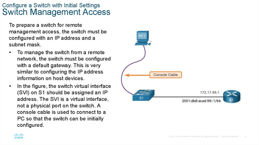
Configure a Switch with Initial SettingsSwitch Management Access
To prepare a switch for remote
management access, the switch must be
configured with an IP address and a
subnet mask.
• To manage the switch from a remote
network, the switch must be configured
with a default gateway. This is very
similar to configuring the IP address
information on host devices.
• In the figure, the switch virtual interface
(SVI) on S1 should be assigned an IP
address. The SVI is a virtual interface,
not a physical port on the switch. A
console cable is used to connect to a
PC so that the switch can be initially
configured.
© 2016 Cisco and/or its affiliates. All rights reserved. Cisco Confidential
9
10.
Configure a Switch with Initial SettingsSwitch SVI Configuration Example
By default, the switch is configured to have its management controlled through VLAN 1. All
ports are assigned to VLAN 1 by default. For security purposes, it is considered a best
practice to use a VLAN other than VLAN 1 for the management VLAN,
Step 1: Configure the Management Interface: From VLAN interface configuration mode,
an IPv4 address and subnet mask is applied to the management SVI of the switch.
Note: The SVI for VLAN 99 will not appear as “up/up” until VLAN 99 is created and there is
a device connected to a switch port associated with VLAN 99.
Note: The switch may need to be configured for IPv6. For example, before you can
configure IPv6 addressing on a Cisco Catalyst 2960 running IOS version 15.0, you will need
to enter the global configuration command sdm prefer dual-ipv4-and-ipv6 default and
then reload the switch.
© 2016 Cisco and/or its affiliates. All rights reserved. Cisco Confidential
10
11.
Configure a Switch with Initial SettingsSwitch SVI Configuration Example (Cont.)
Task
IOS Commands
Enter global configuration mode.
S1# configure terminal
Enter interface configuration mode for the
S1(config)# interface vlan 99
SVI.
Configure the management interface IPv4
S1(config-if)# ip address 172.17.99.11 255.255.255.0
address.
Configure the management interface IPv6
S1(config-if)# ipv6 address 2001:db8:acad:99::1/64
address
Enable the management interface.
S1(config-if)# no shutdown
Return to the privileged EXEC mode.
S1(config-if)# end
Save the running config to the startup
config.
S1# copy running-config startup-config
© 2016 Cisco and/or its affiliates. All rights reserved. Cisco Confidential
11
12.
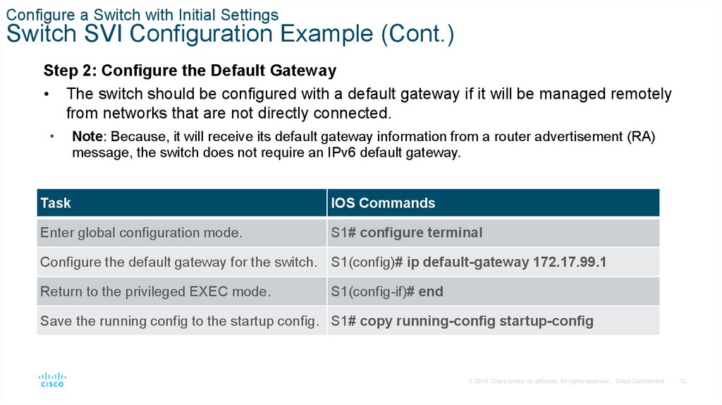
Configure a Switch with Initial SettingsSwitch SVI Configuration Example (Cont.)
Step 2: Configure the Default Gateway
• The switch should be configured with a default gateway if it will be managed remotely
from networks that are not directly connected.
Note: Because, it will receive its default gateway information from a router advertisement (RA)
message, the switch does not require an IPv6 default gateway.
Task
IOS Commands
Enter global configuration mode.
S1# configure terminal
Configure the default gateway for the switch. S1(config)# ip default-gateway 172.17.99.1
Return to the privileged EXEC mode.
S1(config-if)# end
Save the running config to the startup config. S1# copy running-config startup-config
© 2016 Cisco and/or its affiliates. All rights reserved. Cisco Confidential
12
13.
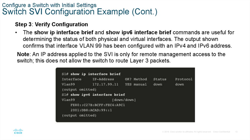
Configure a Switch with Initial SettingsSwitch SVI Configuration Example (Cont.)
Step 3: Verify Configuration
• The show ip interface brief and show ipv6 interface brief commands are useful for
determining the status of both physical and virtual interfaces. The output shown
confirms that interface VLAN 99 has been configured with an IPv4 and IPv6 address.
Note: An IP address applied to the SVI is only for remote management access to the
switch; this does not allow the switch to route Layer 3 packets.
© 2016 Cisco and/or its affiliates. All rights reserved. Cisco Confidential
13
14.
Configure a Switch with Initial SettingsLab – Basic Switch Configuration
In this lab, you will complete the following objectives:
• Part 1: Cable the Network and Verify the Default Switch Configuration
• Part 2: Configure Basic Network Device Settings
• Part 3: Verify and Test Network Connectivity
• Part 4: Manage the MAC Address Table
© 2016 Cisco and/or its affiliates. All rights reserved. Cisco Confidential
14
15.
1.2 Configure Switch Ports© 2016 Cisco and/or its affiliates. All rights reserved. Cisco Confidential
15
16.
Configure Switch PortsDuplex Communication
Full-duplex communication increases bandwidth efficiency by allowing both ends of a
connection to transmit and receive data simultaneously. This is also known as
bidirectional communication and it requires microsegmentation.
A microsegmented LAN is created when a switch port has only one device connected
and is operating in full-duplex mode. There is no collision domain associated with a
switch port operating in full-duplex mode.
Unlike full-duplex communication, half-duplex communication is unidirectional. Halfduplex communication creates performance issues because data can flow in only one
direction at a time, often resulting in collisions.
Gigabit Ethernet and 10 Gb NICs require full-duplex connections to operate. In fullduplex mode, the collision detection circuit on the NIC is disabled. Full-duplex offers
100 percent efficiency in both directions (transmitting and receiving). This results in a
doubling of the potential use of the stated bandwidth.
© 2016 Cisco and/or its affiliates. All rights reserved. Cisco Confidential
16
17.
Configure Switch PortsConfigure Switch Ports at the Physical Layer
Switch ports can be manually configured with specific duplex and speed settings. The respective
interface configuration commands are duplex and speed.
• The default setting for both duplex and speed for switch ports on Cisco Catalyst 2960 and 3560
switches is auto. The 10/100/1000 ports operate in either half- or full-duplex mode when they are
set to 10 or 100 Mbps and operate only in full-duplex mode when it is set to 1000 Mbps (1 Gbps).
• Autonegotiation is useful when the speed and duplex settings of the device connecting to the port
are unknown or may change. When connecting to known devices such as servers, dedicated
workstations, or network devices, a best practice is to manually set the speed and duplex
settings.
• When troubleshooting switch port issues, it is important that the duplex and speed settings are
checked.
Note: Mismatched settings for the duplex mode and speed of switch ports can cause connectivity
issues. Autonegotiation failure creates mismatched settings.
All fiber-optic ports, such as 1000BASE-SX ports, operate only at one preset speed and are always
full-duplex
© 2016 Cisco and/or its affiliates. All rights reserved. Cisco Confidential
17
18.
Configure Switch PortsConfigure Switch Ports at the Physical Layer (Cont.)
Task
IOS Commands
Enter global configuration mode.
S1# configure terminal
Enter interface configuration mode.
S1(config)# interface FastEthernet 0/1
Configure the interface duplex.
S1(config-if)# duplex full
Configure the interface speed.
S1(config-if)# speed 100
Return to the privileged EXEC mode.
S1(config-if)# end
Save the running config to the startup config.
S1# copy running-config startup-config
© 2016 Cisco and/or its affiliates. All rights reserved. Cisco Confidential
18
19.
Configure Switch PortsAuto-MDIX
When automatic medium-dependent interface crossover (auto-MDIX) is enabled, the switch
interface automatically detects the required cable connection type (straight-through or
crossover) and configures the connection appropriately.
• When connecting to switches without the auto-MDIX feature, straight-through cables must
be used to connect to devices such as servers, workstations, or routers. Crossover cables
must be used to connect to other switches or repeaters.
• With auto-MDIX enabled, either type of cable can be used to connect to other devices, and
the interface automatically adjusts to communicate successfully.
• On newer Cisco switches, the mdix auto interface configuration mode command enables
the feature. When using auto-MDIX on an interface, the interface speed and duplex must be
set to auto so that the feature operates correctly.
Note: The auto-MDIX feature is enabled by default on Catalyst 2960 and Catalyst 3560
switches but is not available on the older Catalyst 2950 and Catalyst 3550 switches.
To examine the auto-MDIX setting for a specific interface, use the show controllers ethernetcontroller command with the phy keyword. To limit the output to lines referencing auto-MDIX,
use the include Auto-MDIX filter.
© 2016 Cisco and/or its affiliates. All rights reserved. Cisco Confidential
19
20.
Configure Switch PortsSwitch Verification Commands
Task
IOS Commands
Display interface status and configuration.
S1# show interfaces [interface-id]
Display current startup configuration.
S1# show startup-config
Display current running configuration.
S1# show running-config
Display information about flash file system.
S1# show flash
Display system hardware and software status.
S1# show version
Display history of command entered.
S1# show history
Display IP information about an interface.
S1# show ip interface [interface-id]
OR
S1# show ipv6 interface [interface-id]
Display the MAC address table.
S1# show mac-address-table
OR
S1# show mac address-table
© 2016 Cisco and/or its affiliates. All rights reserved. Cisco Confidential
20
21.
Configure Switch PortsVerify Switch Port Configuration
The show running-config command can be used to verify that the switch has been correctly
configured. From the sample abbreviated output on S1, some important information is shown
in the figure:
• Fast Ethernet 0/18 interface configured with the management VLAN 99
• VLAN 99 configured with an IPv4 address of 172.17.99.11 255.255.255.0
• Default gateway set to 172.17.99.1
© 2016 Cisco and/or its affiliates. All rights reserved. Cisco Confidential
21
22.
Configure Switch PortsVerify Switch Port Configuration (Cont.)
The show interfaces command is another commonly used command, which displays status and
statistics information on the network interfaces of the switch. The show interfaces command is
frequently used when configuring and monitoring network devices.
The first line of the output for the show interfaces fastEthernet 0/18 command indicates that the
FastEthernet 0/18 interface is up/up, meaning that it is operational. Further down, the output shows
that the duplex is full and the speed is 100 Mbps.
© 2016 Cisco and/or its affiliates. All rights reserved. Cisco Confidential
22
23.
Configure Switch PortsNetwork Access Layer Issues
The output from the show interfaces command is useful for detecting common media issues. One of
the most important parts of this output is the display of the line and data link protocol status, as shown
in the example.
The first parameter (FastEthernet0/18 is up) refers to the hardware layer and indicates whether the
interface is receiving a carrier detect signal. The second parameter (line protocol is up) refers to the
data link layer and indicates whether the data link layer protocol keepalives are being received.
Based on the output of the show interfaces command, possible problems can be fixed as follows:
If the interface is up and the line protocol is down, a problem exists. There could be an encapsulation type mismatch, the
interface on the other end could be error-disabled, or there could be a hardware problem.
If the line protocol and the interface are both down, a cable is not attached, or some other interface problem exists. For
example, in a back-to-back connection, the other end of the connection may be administratively down.
If the interface is administratively down, it has been manually disabled (the shutdown command has been issued) in the
active configuration.
© 2016 Cisco and/or its affiliates. All rights reserved. Cisco Confidential
23
24.
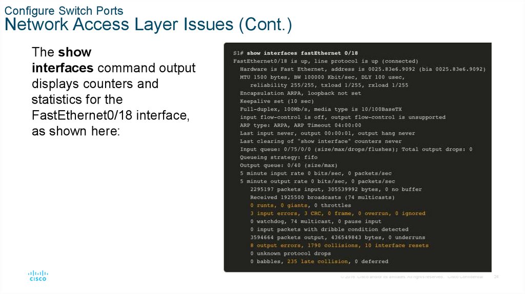
Configure Switch PortsNetwork Access Layer Issues (Cont.)
The show
interfaces command output
displays counters and
statistics for the
FastEthernet0/18 interface,
as shown here:
© 2016 Cisco and/or its affiliates. All rights reserved. Cisco Confidential
24
25.
Configure Switch PortsNetwork Access Layer Issues (Cont.)
Some media errors are not severe enough to cause the circuit to fail but do cause network
performance issues. The table explains some of these common errors which can be
detected using the show interfaces command.
Error Type
Description
Input Errors
Total number of errors. It includes runts, giants, no buffer, CRC, frame, overrun, and ignored counts.
Runts
Packets that are discarded because they are smaller than the minimum packet size for the medium.
For instance, any Ethernet packet that is less than 64 bytes is considered a runt.
Giants
Packets that are discarded because they exceed the maximum packet size for the medium. For
example, any Ethernet packet that is greater than 1,518 bytes is considered a giant.
CRC
CRC errors are generated when the calculated checksum is not the same as the checksum received.
Output Errors
Sum of all errors that prevented the final transmission of datagrams out of the interface that is being
examined.
Collisions
Number of messages retransmitted because of an Ethernet collision.
Late Collisions
A collision that occurs after 512 bits of the frame have been transmitted
© 2016 Cisco and/or its affiliates. All rights reserved. Cisco Confidential
25
26.
Configure Switch PortsInterface Input and Output Errors
“Input errors” is the sum of all errors in datagrams that were received on the interface
being examined. This includes runts, giants, CRC, no buffer, frame, overrun, and ignored
counts. The reported input errors from the show interfaces command include the
following:
Runt Frames - Ethernet frames that are shorter than the 64-byte minimum allowed
length are called runts. Malfunctioning NICs are the usual cause of excessive runt
frames, but they can also be caused by collisions.
Giants - Ethernet frames that are larger than the maximum allowed size are called
giants.
CRC errors - On Ethernet and serial interfaces, CRC errors usually indicate a media
or cable error. Common causes include electrical interference, loose or damaged
connections, or incorrect cabling. If you see many CRC errors, there is too much
noise on the link and you should inspect the cable. You should also search for and
eliminate noise sources.
© 2016 Cisco and/or its affiliates. All rights reserved. Cisco Confidential
26
27.
Configure Switch PortsInterface Input and Output Errors (Cont.)
“Output errors” is the sum of all errors that prevented the final transmission of datagrams
out the interface that is being examined. The reported output errors from the show
interfaces command include the following:
Collisions - Collisions in half-duplex operations are normal. However, you should
never see collisions on an interface configured for full-duplex communication.
Late collisions - A late collision refers to a collision that occurs after 512 bits of the
frame have been transmitted. Excessive cable lengths are the most common cause of
late collisions. Another common cause is duplex misconfiguration.
© 2016 Cisco and/or its affiliates. All rights reserved. Cisco Confidential
27
28.
Configure Switch PortsTroubleshooting Network Access Layer Issues
To troubleshoot
scenarios involving no
connection, or a bad
connection, between a
switch and another
device, follow the
general process
shown in the figure.
© 2016 Cisco and/or its affiliates. All rights reserved. Cisco Confidential
28
29.
1.3 Secure Remote Access© 2016 Cisco and/or its affiliates. All rights reserved. Cisco Confidential
29
30.
Secure Remote AccessTelnet Operation
Telnet uses TCP port 23. It is an older
protocol that uses unsecure plaintext
transmission of both the login
authentication (username and
password) and the data transmitted
between the communicating devices.
A threat actor can monitor packets using
Wireshark. For example, in the figure
the threat actor captured the
username admin and
password ccna from a Telnet session.
© 2016 Cisco and/or its affiliates. All rights reserved. Cisco Confidential
30
31.
Secure Remote AccessSSH Operation
Secure Shell (SSH) is a secure protocol that uses
TCP port 22. It provides a secure (encrypted)
management connection to a remote device.
SSH should replace Telnet for management
connections. SSH provides security for remote
connections by providing strong encryption when
a device is authenticated (username and
password) and also for the transmitted data
between the communicating devices.
The figure shows a Wireshark capture of an SSH
session. The threat actor can track the session
using the IP address of the administrator device.
However, unlike Telnet, with SSH the username
and password are encrypted.
© 2016 Cisco and/or its affiliates. All rights reserved. Cisco Confidential
31
32.
Secure Remote AccessVerify the Switch Supports SSH
To enable SSH on a Catalyst 2960 switch, the switch must be using a version of the IOS
software including cryptographic (encrypted) features and capabilities. Use the show
version command on the switch to see which IOS the switch is currently running. An IOS
filename that includes the combination “k9” supports cryptographic (encrypted) features
and capabilities.
The example shows the output of the show version command.
© 2016 Cisco and/or its affiliates. All rights reserved. Cisco Confidential
32
33.
Secure Remote AccessConfigure SSH
Before configuring SSH, the switch must be minimally configured with a unique hostname and the correct
network connectivity settings.
Step 1: Verify SSH support - Use the show ip ssh command to verify that the switch supports SSH. If the switch is not
running an IOS that supports cryptographic features, this command is unrecognized.
Step 2: Configure the IP domain - Configure the IP domain name of the network using the ip domain-name domainname global configuration mode command.
Step 3: Generate RSA key pairs - Generating an RSA key pair automatically enables SSH. Use the crypto key generate
rsa global configuration mode command to enable the SSH server on the switch and generate an RSA key pair.
Note: To delete the RSA key pair, use the crypto key zeroize rsa global configuration mode command. After the RSA key
pair is deleted, the SSH server is automatically disabled.
Step 4: Configure user authentication - The SSH server can authenticate users locally or using an authentication server. To
use the local authentication method, create a username and password pair using
the username username secret password global configuration mode command.
Step 5: Configure the vty lines - Enable the SSH protocol on the vty lines by using the transport input ssh line configuration
mode command. Use the line vty global configuration mode command and then the login local line configuration mode
command to require local authentication for SSH connections from the local username database.
Step 6: Enable SSH version 2 - By default, SSH supports both versions 1 and 2. When supporting both versions, this is
shown in the show ip ssh output as supporting version 2. Enable SSH version using the ip ssh version 2 global
configuration command.
© 2016 Cisco and/or its affiliates. All rights reserved. Cisco Confidential
33
34.
Secure Remote AccessVerify SSH is Operational
On a PC, an SSH client such as PuTTY, is used to connect to an SSH server. For example, assume the
following is configured:
SSH is enabled on switch S1
Interface VLAN 99 (SVI) with IPv4 address 172.17.99.11 on switch S1
PC1 with IPv4 address 172.17.99.21
Using a terminal emulator, initiate an SSH connection to the SVI VLAN IPv4 address of S1 from PC1.
When connected, the user is prompted for a username and password as shown in the example. Using the
configuration from the previous example, the username admin and password ccna are entered. After
entering the correct combination, the user is connected via SSH to the command line interface (CLI) on the
Catalyst 2960 switch.
© 2016 Cisco and/or its affiliates. All rights reserved. Cisco Confidential
34
35.
Secure Remote AccessVerify SSH is Operational (Cont.)
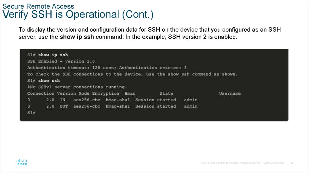
To display the version and configuration data for SSH on the device that you configured as an SSH
server, use the show ip ssh command. In the example, SSH version 2 is enabled.
© 2016 Cisco and/or its affiliates. All rights reserved. Cisco Confidential
35
36.
Secure Remote AccessPacket Tracer – Configure SSH
In this Packet Tracer, you will do the following:
• Secure passwords
• Encrypt communications
• Verify SSH implementation
© 2016 Cisco and/or its affiliates. All rights reserved. Cisco Confidential
36
37.
1.4 Basic RouterConfiguration
© 2016 Cisco and/or its affiliates. All rights reserved. Cisco Confidential
37
38.
Basic Router ConfigurationConfigure Basic Router Settings
Cisco routers and Cisco switches have many similarities. They support a similar modal operating
system, similar command structures, and many of the same commands. In addition, both devices have
similar initial configuration steps. For example, the following configuration tasks should always be
performed. Name the device to distinguish it from other routers and configure passwords, as shown in
the example.
© 2016 Cisco and/or its affiliates. All rights reserved. Cisco Confidential
38
39.
Basic Router ConfigurationConfigure Basic Router Settings (Cont.)
Configure a banner to provide legal notification of unauthorized access, as shown in the
example.
Save the changes on a router, as shown in the example.
© 2016 Cisco and/or its affiliates. All rights reserved. Cisco Confidential
39
40.
Basic Router ConfigurationDual Stack Topology
One distinguishing feature between switches and routers is the type of interfaces
supported by each. For example, Layer 2 switches support LANs; therefore, they have
multiple FastEthernet or Gigabit Ethernet ports. The dual stack topology in the figure is
used to demonstrate the configuration of router IPv4 and IPv6 interfaces.
© 2016 Cisco and/or its affiliates. All rights reserved. Cisco Confidential
40
41.
Basic Router ConfigurationConfigure Router Interfaces
Routers support LANs and WANs and can interconnect different types of networks; therefore, they
support many types of interfaces. For example, G2 ISRs have one or two integrated Gigabit
Ethernet interfaces and High-Speed WAN Interface Card (HWIC) slots to accommodate other types
of network interfaces, including serial, DSL, and cable interfaces.
To be available, an interface must be:
Configured with at least one IP address - Use the ip address ip-address subnet-mask and
the ipv6 address ipv6-address/prefix interface configuration commands.
Activated - By default, LAN and WAN interfaces are not activated (shutdown). To enable an
interface, it must be activated using the no shutdown command. (This is similar to powering
on the interface.) The interface must also be connected to another device (a hub, a switch, or
another router) for the physical layer to be active.
Description - Optionally, the interface could also be configured with a short description of up to
240 characters. It is good practice to configure a description on each interface. On production
networks, the benefits of interface descriptions are quickly realized as they are helpful in
troubleshooting and in identifying a third-party connection and contact information.
© 2016 Cisco and/or its affiliates. All rights reserved. Cisco Confidential
41
42.
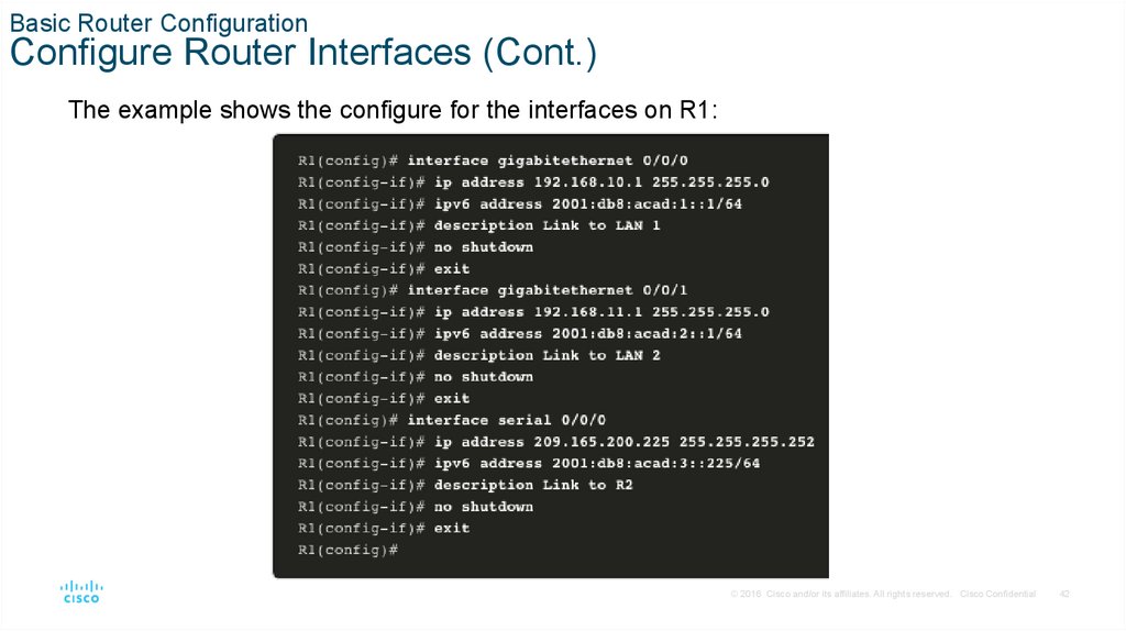
Basic Router ConfigurationConfigure Router Interfaces (Cont.)
The example shows the configure for the interfaces on R1:
© 2016 Cisco and/or its affiliates. All rights reserved. Cisco Confidential
42
43.
Basic Router ConfigurationIPv4 Loopback Interfaces
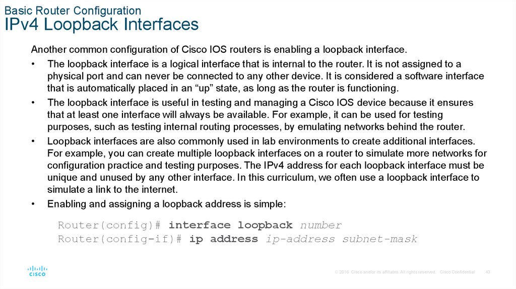
Another common configuration of Cisco IOS routers is enabling a loopback interface.
• The loopback interface is a logical interface that is internal to the router. It is not assigned to a
physical port and can never be connected to any other device. It is considered a software interface
that is automatically placed in an “up” state, as long as the router is functioning.
• The loopback interface is useful in testing and managing a Cisco IOS device because it ensures
that at least one interface will always be available. For example, it can be used for testing
purposes, such as testing internal routing processes, by emulating networks behind the router.
• Loopback interfaces are also commonly used in lab environments to create additional interfaces.
For example, you can create multiple loopback interfaces on a router to simulate more networks for
configuration practice and testing purposes. The IPv4 address for each loopback interface must be
unique and unused by any other interface. In this curriculum, we often use a loopback interface to
simulate a link to the internet.
• Enabling and assigning a loopback address is simple:
Router(config)# interface loopback number
Router(config-if)# ip address ip-address subnet-mask
© 2016 Cisco and/or its affiliates. All rights reserved. Cisco Confidential
43
44.
Basic Router ConfigurationPacket Tracer – Configure Router Interfaces
In this Packet Tracer activity, you will do the following:
• Configure IPv4 addressing and verify connectivity
• Configure IPv6 addressing and verify connectivity
© 2016 Cisco and/or its affiliates. All rights reserved. Cisco Confidential
44
45.
1.5 Verify Directly ConnectedNetworks
© 2016 Cisco and/or its affiliates. All rights reserved. Cisco Confidential
45
46.
Verify Directly Connected NetworksInterface Verification Commands
There are several show commands that can be used to verify the operation and
configuration of an interface.
The following commands are especially useful to quickly identify the status of an interface:
show ip interface brief and show ipv6 interface brief - These display a summary
for all interfaces including the IPv4 or IPv6 address of the interface and current
operational status.
show running-config interface interface-id - This displays the commands applied to
the specified interface.
show ip route and show ipv6 route - These display the contents of the IPv4 or IPv6
routing table stored in RAM. In Cisco IOS 15, active interfaces should appear in the
routing table with two related entries identified by the code ‘C’ (Connected) or ‘L’
(Local). In previous IOS versions, only a single entry with the code ‘C’ will appear.
© 2016 Cisco and/or its affiliates. All rights reserved. Cisco Confidential
46
47.
Verify Directly Connected NetworksVerify Interface Status
The output of the show ip interface brief and show ipv6 interface brief commands can be used to quickly
reveal the status of all interfaces on the router. You can verify that the interfaces are active and operational as
indicated by the Status of “up” and Protocol of “up”, as shown in the example. A different output would
indicate a problem with either the configuration or the cabling.
© 2016 Cisco and/or its affiliates. All rights reserved. Cisco Confidential
47
48.
Verify Directly Connected NetworksVerify IPv6 Link Local and Multicast Addresses
The output of the show ipv6 interface brief command displays two configured IPv6 addresses per
interface. One address is the IPv6 global unicast address that was manually entered. The other
address, which begins with FE80, is the link-local unicast address for the interface. A link-local
address is automatically added to an interface whenever a global unicast address is assigned. An
IPv6 network interface is required to have a link-local address, but not necessarily a global unicast
address.
The show ipv6 interface gigabitethernet 0/0/0 command displays the interface status and all of
the IPv6 addresses belonging to the interface. Along with the link local address and global unicast
address, the output includes the multicast addresses assigned to the interface, beginning with prefix
FF02, as shown in the example.
© 2016 Cisco and/or its affiliates. All rights reserved. Cisco Confidential
48
49.
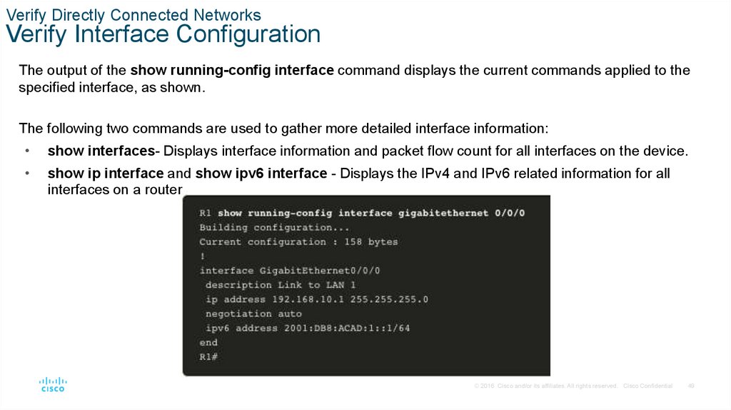
Verify Directly Connected NetworksVerify Interface Configuration
The output of the show running-config interface command displays the current commands applied to the
specified interface, as shown.
The following two commands are used to gather more detailed interface information:
show interfaces- Displays interface information and packet flow count for all interfaces on the device.
show ip interface and show ipv6 interface - Displays the IPv4 and IPv6 related information for all
interfaces on a router..
© 2016 Cisco and/or its affiliates. All rights reserved. Cisco Confidential
49
50.
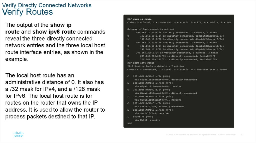
Verify Directly Connected NetworksVerify Routes
The output of the show ip
route and show ipv6 route commands
reveal the three directly connected
network entries and the three local host
route interface entries, as shown in the
example.
The local host route has an
administrative distance of 0. It also has
a /32 mask for IPv4, and a /128 mask
for IPv6. The local host route is for
routes on the router that owns the IP
address. It is used to allow the router to
process packets destined to that IP.
© 2016 Cisco and/or its affiliates. All rights reserved. Cisco Confidential
50
51.
Verify Directly Connected NetworksVerify Routes (Cont.)
A ‘C’ next to a route within the routing table
indicates that this is a directly connected
network. When the router interface is
configured with a global unicast address and
is in the “up/up” state, the IPv6 prefix and
prefix length are added to the IPv6 routing
table as a connected route.
The IPv6 global unicast address applied to
the interface is also installed in the routing
table as a local route. The local route has a
/128 prefix. Local routes are used by the
routing table to efficiently process packets
with the interface address of the router as
the destination.
© 2016 Cisco and/or its affiliates. All rights reserved. Cisco Confidential
51
52.
Verify Directly Connected NetworksFilter Show Command Output
Commands that generate multiple screens of output are, by default, paused after 24 lines. At the end of
the paused output, the --More-- text displays. Pressing Enter displays the next line and pressing the
spacebar displays the next set of lines. Use the terminal length command to specify the number of
lines to be displayed. A value of 0 (zero) prevents the router from pausing between screens of output.
Another very useful feature that improves the user experience in the CLI is the filtering of show output.
Filtering commands can be used to display specific sections of output. To enable the filtering
command, enter a pipe (|) character after the show command and then enter a filtering parameter and
a filtering expression.
There are four filtering parameters that can be configured after the pipe:
section - Shows the entire section that starts with the filtering expression.
include - Includes all output lines that match the filtering expression.
exclude - Excludes all output lines that match the filtering expression.
begin - Shows all the output lines from a certain point, starting with the line that matches the filtering expression
© 2016 Cisco and/or its affiliates. All rights reserved. Cisco Confidential
52
53.
Verify Directly Connected NetworksCommand History Feature
The command history feature is useful because it temporarily stores the list of executed
commands to be recalled.
• To recall commands in the history buffer, press Ctrl+P or the Up Arrow key. The
command output begins with the most recent command. Repeat the key sequence to
recall successively older commands. To return to more recent commands in the history
buffer, press Ctrl+N or the Down Arrow key. Repeat the key sequence to recall
successively more recent commands.
• By default, command history is enabled and the system captures the last 10 command
lines in its history buffer. Use the show history privileged EXEC command to display
the contents of the buffer.
• It is also practical to increase the number of command lines that the history buffer
records during the current terminal session only. Use the terminal history size user
EXEC command to increase or decrease the size of the buffer.
© 2016 Cisco and/or its affiliates. All rights reserved. Cisco Confidential
53
54.
Verify Directly Connected NetworksPacket Tracer – Verify Directly Connected Networks
In this Packet Tracer activity, you will complete the following objectives:
• Verify IPv4 directly connected networks
• Verify IPv6 directly connected networks
• Troubleshoot connectivity issues
© 2016 Cisco and/or its affiliates. All rights reserved. Cisco Confidential
54
55.
1.6 Module Practice and Quiz© 2016 Cisco and/or its affiliates. All rights reserved. Cisco Confidential
55
56.
Module Practice and QuizPacket Tracer – Implement a Small Network
In this Packet Tracer activity, you will do the following:
• Create a network topology
• Configure devices and verify connectivity
© 2016 Cisco and/or its affiliates. All rights reserved. Cisco Confidential
56
57.
Module Practice and QuizLab– Configure Basic Router Settings
In this lab, you will complete the following objectives:
• Set up the topology and initialize devices
• Cable equipment to match the network topology
• Initialize and restart the router and switch
• Configure devices and verify connectivity
• Assign static IPv4 and IPv6 information to the PC interface
• Configure basic router settings
• Configure the router for SSH
• Verify network connectivity
© 2016 Cisco and/or its affiliates. All rights reserved. Cisco Confidential
57