 Промышленность
Похожие презентации:


United States Patent USOO752001.4B2
1.
USOO752001.4B2(12) United States Patent
Homsi
(10) Patent No.:
US 7,520,014 B2
(45) Date of Patent:
(54) METHOD AND APPARATUS FOR BRIDGE
Apr. 21, 2009
3,571,835 A * 3/1971 Buechler .................... 14,771
CONSTRUCTION
3,902,212 A *
9/1975 Muller ...
... 14.77.1
4,141,668 A * 2/1979 Engel .....
... 405,202
(75) Inventor: Elie H. Homsi, Broomfield, CO (US)
4,282,978
A 8, 1981 Zambon ...
4,302,052 A * 1 1/1981 Fischer ...
...... 212/312
175.67
(73) Assignee: Fairs Constructors, Inc., Longmont,
4,799,279 A * 1/1989 Muller ...
... 14.77.1
4,923,334. A * 5/1990 Masoudi ....
5,072.474. A * 12/1991 Dil
tal. ...
... 405,203
... 14.77.1
(*)
Notice:
4,651.375 A
Subject to any disclaimer, the term of this
5,173,981 A *
patent is extended or adjusted under 35
U.S.C. 154(b) by 0 days.
5,915,423 A
6/1999 Thomas ........................ 14/24
5,947,308 A * 9/1999 Markelz ....
... 212,294
Dec. 20, 2006
(65)
12/1992
Eli, - - - - - - - - - - - - - - - - - - - 14/24
6,721,985 B2 * 4/2004 McCrary .................... 14,771
7,159,262 B2 1/2007 Jackson ...................... 14,771
7,210,183 B2 * 5/2007 Kornatsky ..
... 14.77.1
(21) Appl. No.: 11/613,945
(22) Filed:
3/1987 Macchi ............................ 14.7
2003/0217420 A1* 11/2003 Snead ..............
Prior Publication Data
... 14.77.1
2004/01 11815 A1* 6/2004 Fuessinger et al.
... 14.77.1
2004/0148717 A1* 8/2004 Kornatsky ................... 14,771
2004/0226118 A1 * 1 1/2004 Buonomo ................... 14,771
US 2007/0163058 A1
Jul 19, 2007
2004/025.3087 A1* 12/2004 Iizuka ........................ 414,626
Related U.S. Application Data
(60) Provisional application No. 60/751,897, filed on Dec.
20, 2005.
* cited by examiner
Primary Examiner Raymond W Addie
(74) Attorney, Agent, or Firm—Christopher J. Kulish, P.C.
(51) Int. Cl.
(57)
EOID 2L/00
EOID 9/00
(2006.01)
(52) U.S. Cl. ......................................... 14/77.1: 14/77.3
(58) Field of Classification Search ................... 14777.1
See application file for complete search history.
(56)
ABSTRACT
(2006.01)
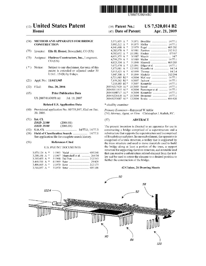
The present invention is directed to an apparatus for use in
constructing a bridge comprised of a SuperStructure and a
substructure that supports the superstructure and is comprised
of foundations and piers. In one embodiment, the apparatus is
comprised of a truss structure, a trolley that is Supported by
References Cited
the truss structure and used to move materials used to build
U.S. PATENT DOCUMENTS
the bridge along at least a portion of the truss, a Support
structure for Supporting the truss structure, and rotatable lead
3,073,124. A
3,299,191 A *
3,385.455 A *
3,448,511 A
3,490,605 A *
3,511,057 A *
1, 1963 Nadal ......................... 405,240
1/1967 Mantscheffet al. ........... 264/34
5/1968 Dal Pont ............. ... 212,343
6, 1969 Suter ........................... 29,429
1/1970 Koss ...
... 212,175
5, 1970 Suter .......................... 405,196
that can receive a substructure related element from the trol
ley and be used to rotate the element to a desired position to
further the construction of the bridge.
42 Claims, 26 Drawing Sheets
-
58
12O
2.
U.S. PatentApr. 21, 2009
Sheet 1 of 26
US 7,520,014 B2
3.
U.S. PatentApr. 21, 2009
Sheet 2 of 26
US 7,520,014 B2
4.
U.S. PatentApr. 21, 2009
Sheet 3 of 26
US 7,520,014 B2
5.
U.S. PatentApr. 21, 2009
Sheet 4 of 26
US 7,520,014 B2
6.
U.S. PatentApr. 21, 2009
Sheet 5 of 26
US 7,520,014 B2
7.
U.S. PatentApr. 21, 2009
US 7,520,014 B2
Sheet 6 of 26
OOJ
8.
U.S. PatentApr. 21, 2009
US 7,520,014 B2
Sheet 7 of 26
OOJ
9.
U.S. PatentApr. 21, 2009
OTT
Sheet 8 of 26
US 7,520,014 B2
10.
U.S. PatentApr. 21, 2009
Sheet 9 of 26
US 7,520,014 B2
s
11.
Apr. 21, 2009Sheet 10 of 26
US 7,520,014 B2
12.
U.S. PatentApr. 21, 2009
Sheet 11 of 26
US 7,520,014 B2
13.
U.S. PatentApr. 21, 2009
86
Sheet 12 of 26
US 7,520,014 B2
14.
U.S. PatentApr. 21, 2009
Sheet 13 of 26
US 7,520,014 B2
15.
U.S. PatentApr. 21, 2009
Sheet 14 of 26
US 7,520,014 B2
OZI
16.
U.S. PatentApr. 21, 2009
Sheet 15 of 26
US 7,520,014 B2
? S
17.
U.S. PatentFIG.16A
FIG.16C
Apr. 21, 2009
Sheet 16 of 26
US 7,520,014 B2
18.
U.S. PatentApr. 21, 2009
Sheet 17 of 26
FIG.16B
US 7,520,014 B2
19.
U.S. PatentApr. 21, 2009
Sheet 18 of 26
US 7,520,014 B2
S
s
s
CO
(Y
Vs
20.
U.S. PatentApr. 21, 2009
Sheet 19 of 26
US 7,520,014 B2
214A
212A
O 4.
214A
N-1
2TO
2OO
/N212A
3 -
N-1
2O3A
aul 204
2O3A
sa
/N/
2O6
2O2A
FIG.18A
S-7 / 228
224
224A s
222A ?
2
FIG.18B
/
U 222A
226
CD
22O
21.
U.S. PatentApr. 21, 2009
Sheet 20 of 26
US 7,520,014 B2
22.
U.S. PatentApr. 21, 2009
42O
Sheet 21 of 26
US 7,520,014 B2
23.
U.S. PatentApr. 21, 2009
Sheet 22 of 26
US 7,520,014 B2
4O6
4O3
FIG.21
24.
U.S. PatentApr. 21, 2009
Sheet 23 of 26
US 7,520,014 B2
25.
U.S. PatentApr. 21, 2009
Sheet 24 of 26
US 7.520,014 B2
26.
U.S. PatentApr. 21, 2009
Sheet 25 of 26
FIG.25
US 7,520,014 B2
27.
U.S. PatentApr. 21, 2009
Sheet 26 of 26
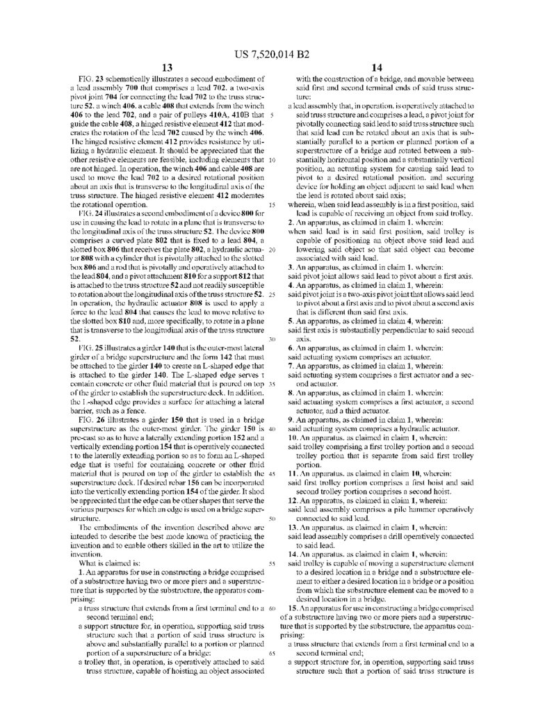
156
FIG.26
US 7,520,014 B2
28.
US 7,520,014 B21.
2
the bridge. In many case, the temporary Support structure
adversely affects the portions of the watercourse or wetland
that are outside the footprint of the bridge. Typically, the
CROSS REFERENCE TO RELATED
temporary Support structure Supports a first crane to which a
APPLICATIONS
pile driver has been attached, a second crane for loading a pile
into the pile driver associated with the first crane, a third crane
This application claims the benefit of U.S. Provisional for constructing a pier on each of the foundations established
Application No. 60/751,897, entitled “METHOD AND by the first and second cranes, and a fourth crane for putting
APPARATUS FOR CONSTRUCTING A BRIDGE and
the girders in place between adjacent piers. In some cases, the
filed by Elie H. Homsi on Dec. 20, 2005, which application is 10 third and/or fourth crane are replaced with a moveable gantry
incorporated by reference into this application in its entirety. or truss that spans the distance between at least two adjacent
piers and is located above and substantially parallel to the
FIELD OF THE INVENTION
SuperStructure to construct the piers and establish girders
between adjacent piers.
The present invention is directed to an apparatus for use in 15 Also associated with the construction of bridges is the
constructing a bridge and a method for constructing a bridge. attachment of L-shaped form to the outer-most lateral girders
and the Subsequent pouring of concrete into the forms to
BACKGROUND OF THE INVENTION
establish an L-shaped concrete member along the lateral
edges of the SuperStructure. These L-shaped members typi
The main elements of the type of bridge to which the cally facilitate the establishment of barriers along the lateral
invention is directed are:
edges of the Superstructure and serve to contain the concrete
(a) a Substructure; and (b) a SuperStructure.
or other fluid material that is used to establish the superstruc
A Substructure is comprised of (1) foundations and (2) ture deck.
piers. The foundations are the components of the substructure
SUMMARY OF THE INVENTION
that engage or interact with the earth to support the bridge 25
METHOD AND APPARATUS FOR BRIDGE
CONSTRUCTION
structure. A foundation can be constructed of one or more
The present invention is directed to an apparatus and
piles, one or more concrete drilled shafts, one or more con
crete mats, and combinations thereof. Presently, piles include method for use in constructing a bridge that Substantially
precast concrete piles and steel piles. The piers are the com avoids the need for a temporary Support structure for cranes
ponents of the substructure that transfer the bridge structural 30 and other machinery and/or the need to use conventional
loads to the foundations. A pier can be constructed of col cranes to manipulate the main elements of the Substructure
umns, struts, pile caps, pier caps, and combinations thereof. and superstructure that are used to form the bridge.
Presently, columns include cast in place columns, precast
In one embodiment, the apparatus is comprised of: (a) a
concrete columns, and steel columns.
truss structure that extends from a first end to a second end, (b)
A superstructure carries the traffic load (vehicular, rail, 35 a Support structure that, in operation, Supports the truss struc
and/or pedestrian) on the bridge. A SuperStructure can be ture such that a portion of the truss structure is above and
constructed using girders that each typically span the distance Substantially parallel to the SuperStructure or planned location
between two adjacent piers. Presently, girders include precast of a portion of the SuperStructure, (c) a trolley that, in opera
concrete girders, cast in place girders, precast concrete box tion, is Supported by the truss structure, capable of hoisting an
girders, segmental box girders, steel girders, and steel box 40 object associated with the building the bridge, and movable
girders. Some SuperStructures use two or more different types between the ends of the truss structure, (d) a lead assembly
of girders.
that, in operation, is operatively attached to the truss structure
Presently, there are several methods of constructing a and comprises a lead, a pivotjoint for pivotally connecting the
bridge comprised of a Substructure and a SuperStructure lead to the truss structure, and an actuating system for causing
(hereinafter referred to as a “bridge') in situations in which 45 the lead to pivot to a desired rotation position. When the lead
there is limited access from the ground. Characteristic of each is in a predefined position, the lead is capable of receiving an
method is the use of one or more conventional cranes that are
object from the trolley. For example, the lead can receive a
each capable of rotating a boom about horizontal and Vertical pile from the trolley and rotate the pile to place the pile in the
axes to either move an element of bridge into place or manipu desired rotational orientation for establishing a pier.
late a tool that is used in constructing the bridge. One method 50 Another embodiment of the apparatus comprises a lead
employs a crane that is positioned on top of and near the end assembly that comprises a lead, a pivot joint for pivotally
of the existing SuperStructure to position a pile driver and a connecting the lead to the truss structure, an actuator system
pile beyond the end of the superstructure so that the pile can for causing the lead to pivot to a desired rotational position,
be driven into the earth to form the next foundation. Typically, and a tool that is operatively attached to the lead. In one
a second crane is used to provide piles to the pile driver 55 embodiment, the tool is a hammer that is used to drive a pile
associated with the first crane, construct the pier that engages that is held by the lead into the ground. In another embodi
the pile or piles of the foundation established by the first ment, the tool is a drill that is used in drilling a hole for
acceptingaportion of a pile or in drilling a hole for a concrete
crane, and construct the, either alone or in combination with
the first crane, the superstructure. A drawback associated with drilled shaft, i.e., a concrete pile that is formed by excavating
this method is that the piers must be spaced relatively close 60 a hole within a casing that has been hammered or otherwise
together due to the construction loads imposed upon the driven into the ground, filling the hole with concrete, and
Subsequently removing the casing. Yet a further embodiment
bridge by the crane, the pile driver, and the pile.
Another method for constructing a bridge when the bridge comprises a conveyor system that is used to remove the earth
is being built over a watercourse or wetland involves using a that the drill excavates from a hole that is being established in
temporary structure that extends outside the footprint of the 65 the ground.
resulting bridge to support cranes and the like that are used in
Yet a further embodiment of the apparatus comprises a
constructing the bridge and, in particular, the Substructure of lead, a two-axis pivot joint for connect the lead to the truss
29.
US 7,520,014 B23
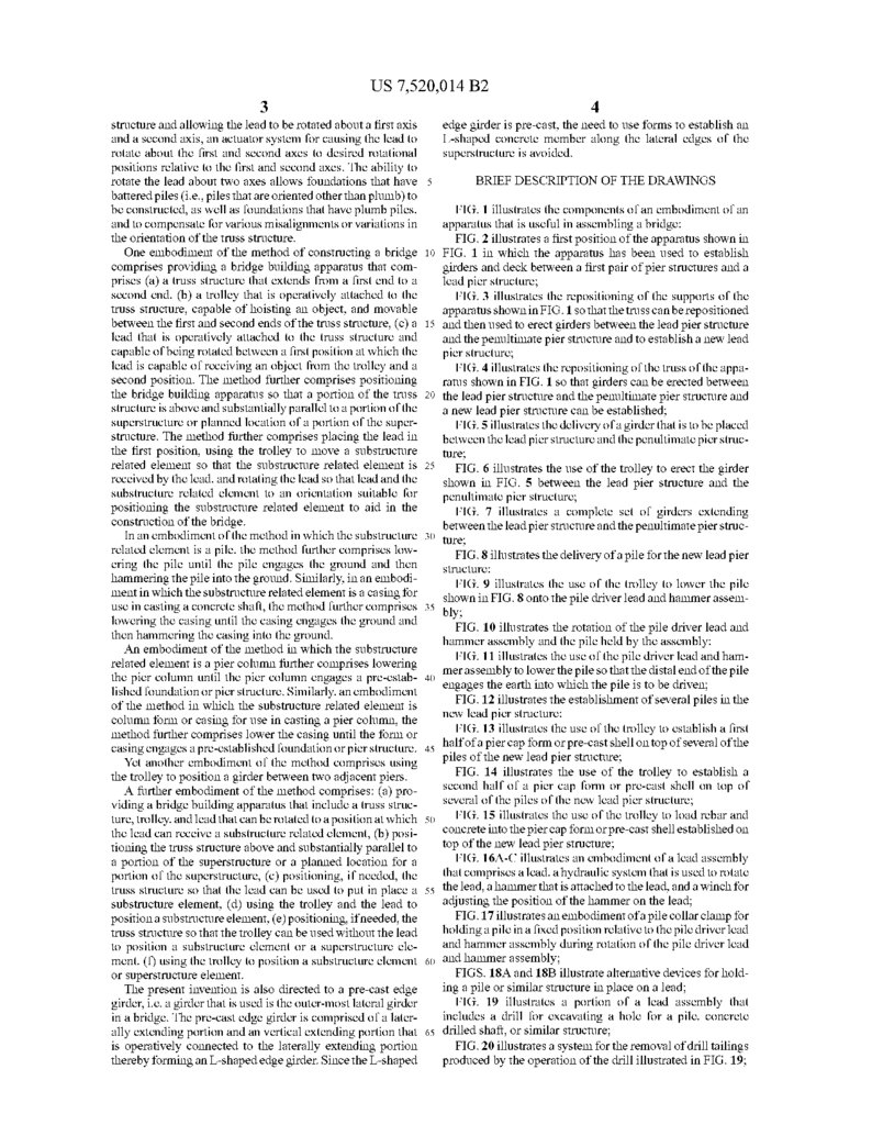
structure and allowing the lead to be rotated about a first axis
and a second axis, an actuator system for causing the lead to
rotate about the first and second axes to desired rotational
4
edge girder is pre-cast, the need to use forms to establish an
L-shaped concrete member along the lateral edges of the
SuperStructure is avoided.
positions relative to the first and second axes. The ability to
rotate the lead about two axes allows foundations that have
battered piles (i.e., piles that are oriented other than plumb) to
be constructed, as well as foundations that have plumb piles,
and to compensate for various misalignments or variations in
BRIEF DESCRIPTION OF THE DRAWINGS
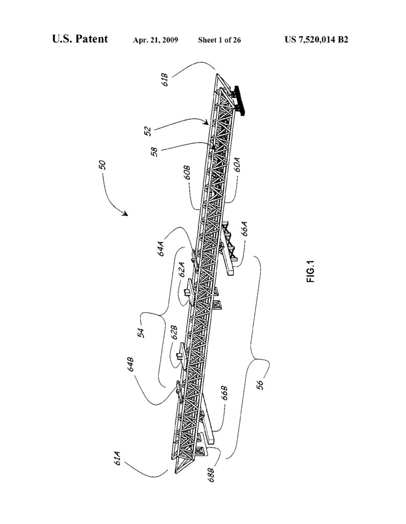
FIG. 1 illustrates the components of an embodiment of an
apparatus that is useful in assembling a bridge;
the orientation of the truss structure.
FIG. 2 illustrates a first position of the apparatus shown in
One embodiment of the method of constructing a bridge 10 FIG. 1 in which the apparatus has been used to establish
comprises providing a bridge building apparatus that com girders and deck between a first pair of pier structures and a
prises (a) a truss structure that extends from a first end to a lead pier structure;
second end, (b) a trolley that is operatively attached to the
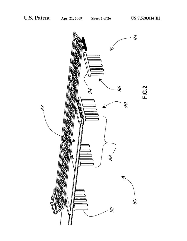
FIG. 3 illustrates the repositioning of the supports of the
truss structure, capable of hoisting an object, and movable apparatus shown in FIG.1 so that the truss can be repositioned
between the first and second ends of the truss structure, (c) a 15 and then used to erect girders between the lead pier structure
lead that is operatively attached to the truss structure and and the penultimate pier structure and to establish a new lead
capable of being rotated between a first position at which the pier structure;
lead is capable of receiving an object from the trolley and a
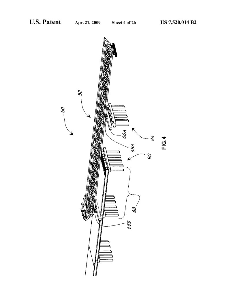
FIG. 4 illustrates the repositioning of the truss of the appa
second position. The method further comprises positioning ratus shown in FIG. 1 so that girders can be erected between
the bridge building apparatus So that a portion of the truss the lead pier structure and the penultimate pier structure and
structure is above and substantially parallel to a portion of the a new lead pier structure can be established;
SuperStructure or planned location of a portion of the Super
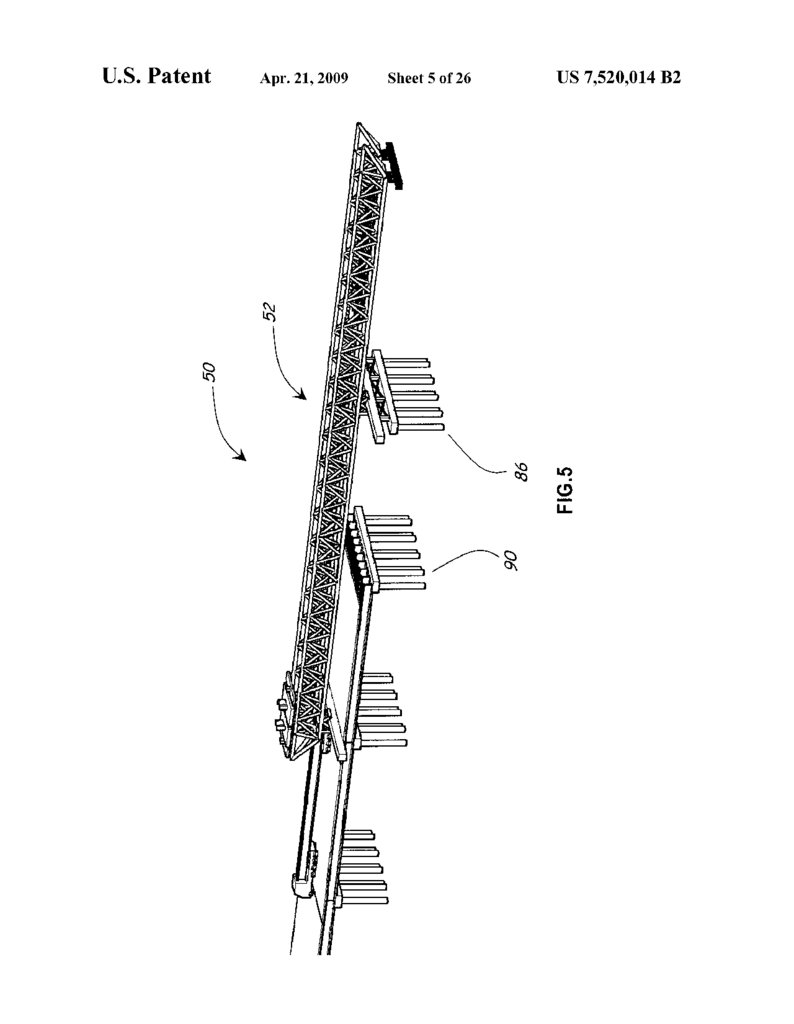
FIG. 5 illustrates the delivery of a girder that is to be placed
structure. The method further comprises placing the lead in between the lead pier structure and the penultimate pier struc
the first position, using the trolley to move a substructure ture;
related element so that the substructure related element is 25
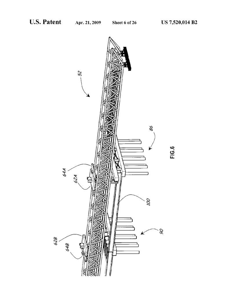
FIG. 6 illustrates the use of the trolley to erect the girder
received by the lead, and rotating the lead so that lead and the shown in FIG. 5 between the lead pier structure and the
substructure related element to an orientation suitable for
penultimate pier structure;
positioning the Substructure related element to aid in the
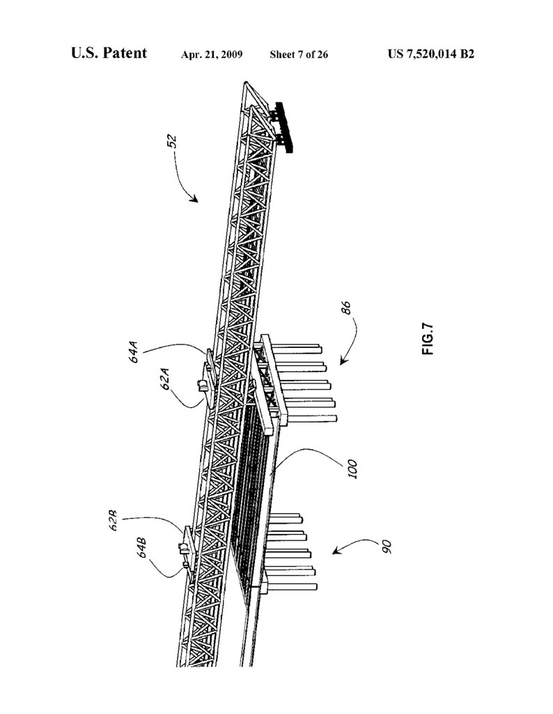
FIG. 7 illustrates a complete set of girders extending
construction of the bridge.
between
the lead pier structure and the penultimate pier struc
In an embodiment of the method in which the substructure 30 ture;
related element is a pile, the method further comprises low
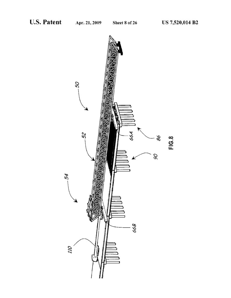
FIG. 8 illustrates the delivery of a pile for the new lead pier
ering the pile until the pile engages the ground and then Structure:
hammering the pile into the ground. Similarly, in an embodi
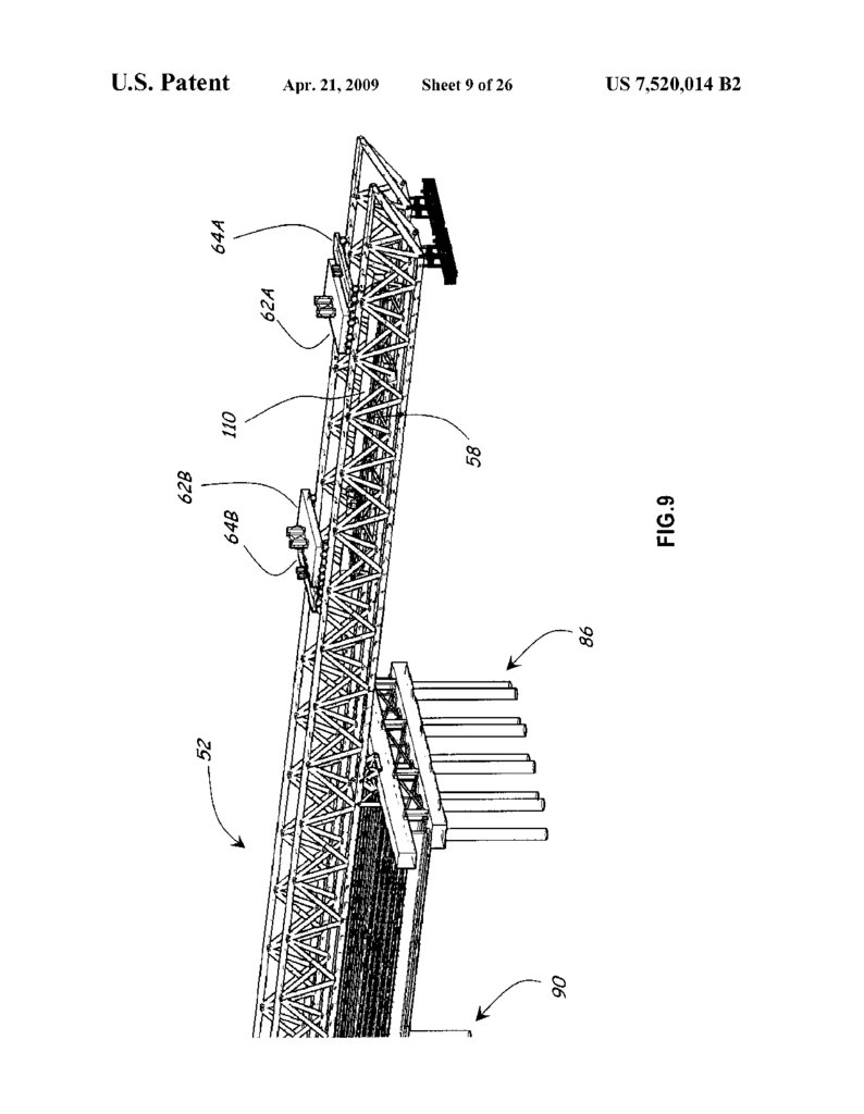
FIG. 9 illustrates the use of the trolley to lower the pile
ment in which the Substructure related element is a casing for shown in FIG.8 onto the pile driver lead and hammer assem
use in casting a concrete shaft, the method further comprises 35 bly:
lowering the casing until the casing engages the ground and
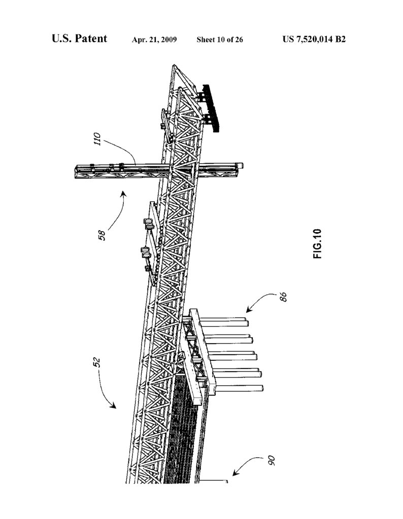
FIG. 10 illustrates the rotation of the pile driver lead and
then hammering the casing into the ground.
hammer
assembly and the pile held by the assembly:
An embodiment of the method in which the substructure
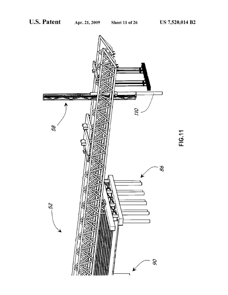
FIG.
11
illustrates the use of the pile driver lead and ham
related element is a pier column further comprises lowering merassembly
to lower the pile so that the distal end of the pile
the pier column until the pier column engages a pre-estab 40 engages the earth
into which the pile is to be driven;
lished foundation or pier structure. Similarly, an embodiment
FIG.
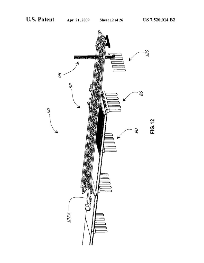
12
illustrates
the establishment of several piles in the
of the method in which the substructure related element is
column form or casing for use in casting a pier column, the new lead pier structure;
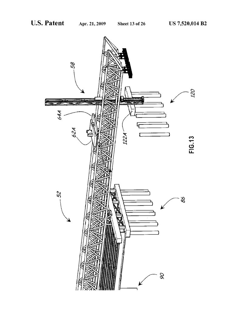
13 illustrates the use of the trolley to establish a first
method further comprises lower the casing until the form or halfFIG.
of a pier cap form or pre-cast shell on top of several of the
casing engages a pre-established foundation or pier structure. 45
Yet another embodiment of the method comprises using piles of the new lead pier structure;
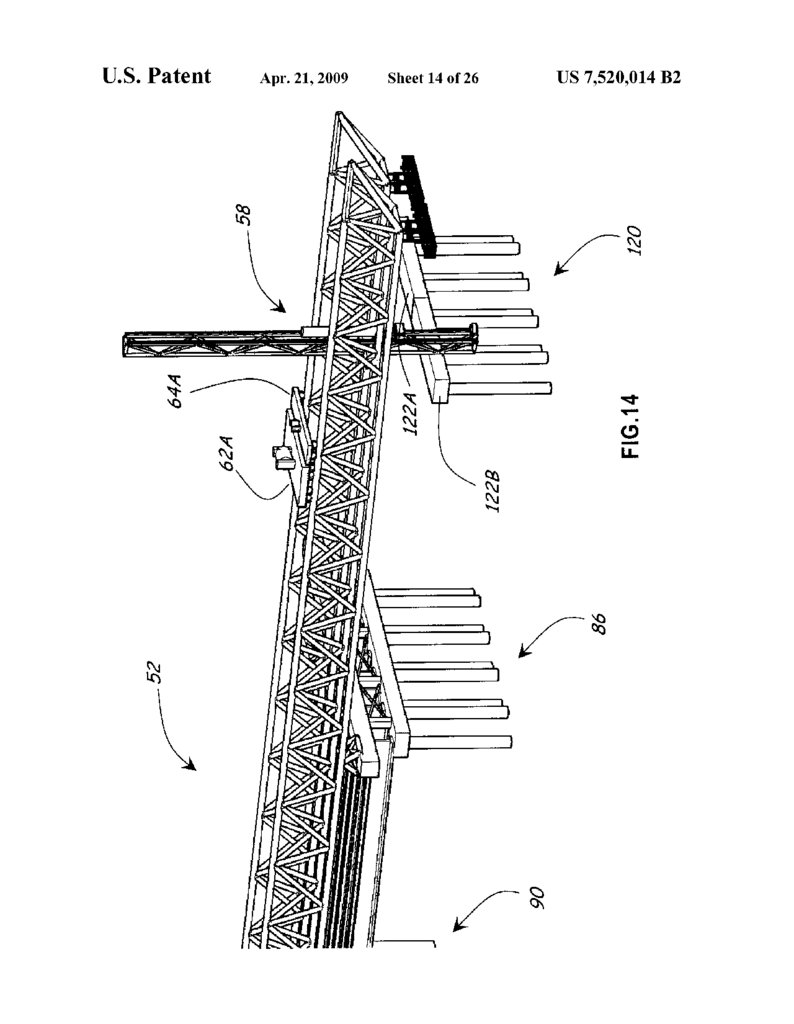
FIG. 14 illustrates the use of the trolley to establish a
the trolley to position a girder between two adjacent piers.
A further embodiment of the method comprises: (a) pro second half of a pier cap form or pre-cast shell on top of
viding a bridge building apparatus that include a truss struc several of the piles of the new lead pier structure:
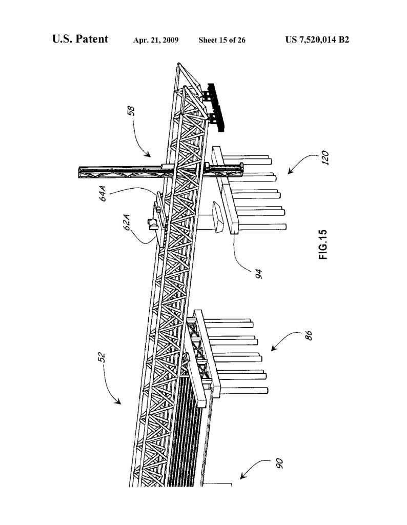
ture, trolley, and lead that can be rotated to a position at which 50 FIG. 15 illustrates the use of the trolley to load rebar and
the lead can receive a substructure related element, (b) posi concrete into the pier cap form or pre-cast shell established on
tioning the truss structure above and Substantially parallel to top of the new lead pier structure:
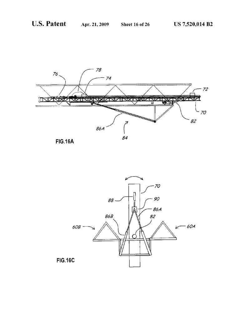
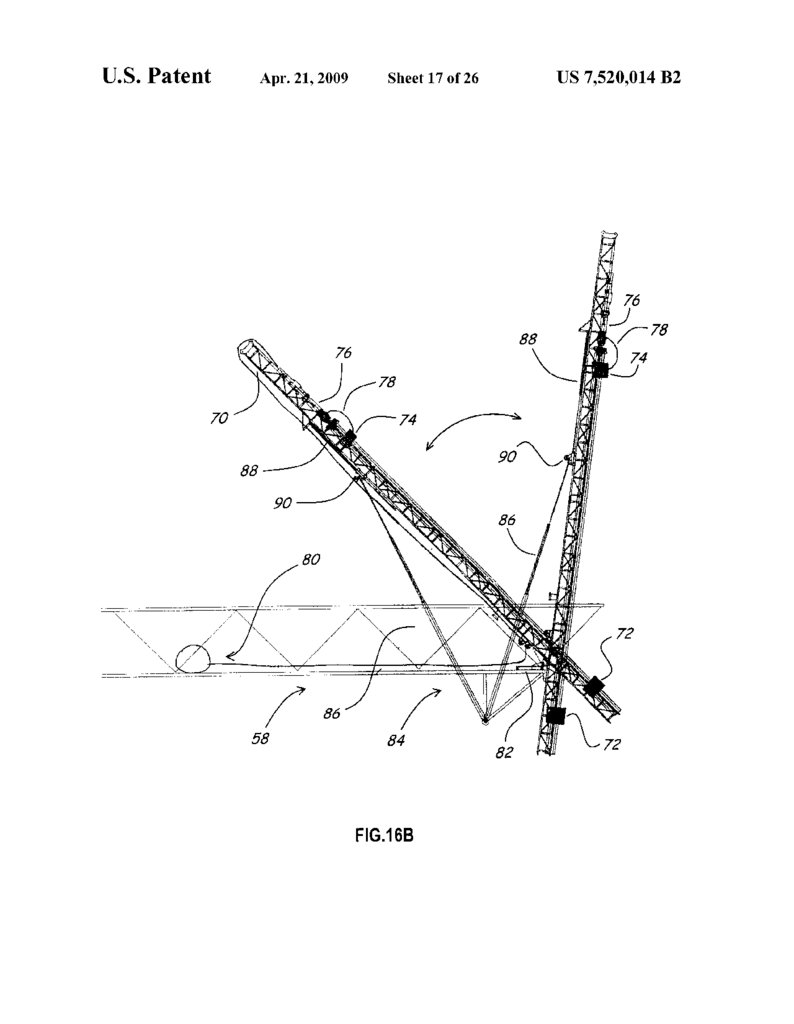
FIG.16A-C illustrates an embodiment of a lead assembly
a portion of the Superstructure or a planned location for a
portion of the SuperStructure, (c) positioning, if needed, the that comprises a lead, a hydraulic system that is used to rotate
truss structure so that the lead can be used to put in place a 55 the lead, a hammer that is attached to the lead, and a winch for
substructure element, (d) using the trolley and the lead to adjusting the position of the hammer on the lead;
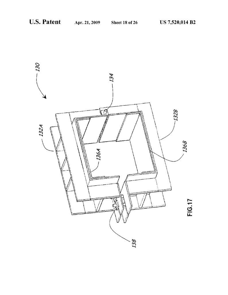
FIG.17 illustrates an embodiment of a pile collar clamp for
position a Substructure element, (e) positioning, if needed, the
truss structure so that the trolley can be used without the lead holding a pile in a fixed position relative to the pile driver lead
to position a Substructure element or a SuperStructure ele and hammer assembly during rotation of the pile driver lead
ment, (f) using the trolley to position a Substructure element 60 and hammer assembly:
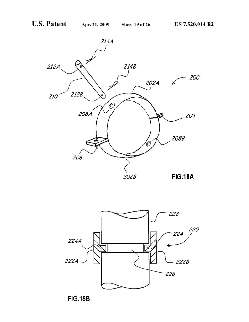
FIGS. 18A and 18B illustrate alternative devices for hold
or Superstructure element.
The present invention is also directed to a pre-cast edge ing a pile or similar structure in place on a lead;
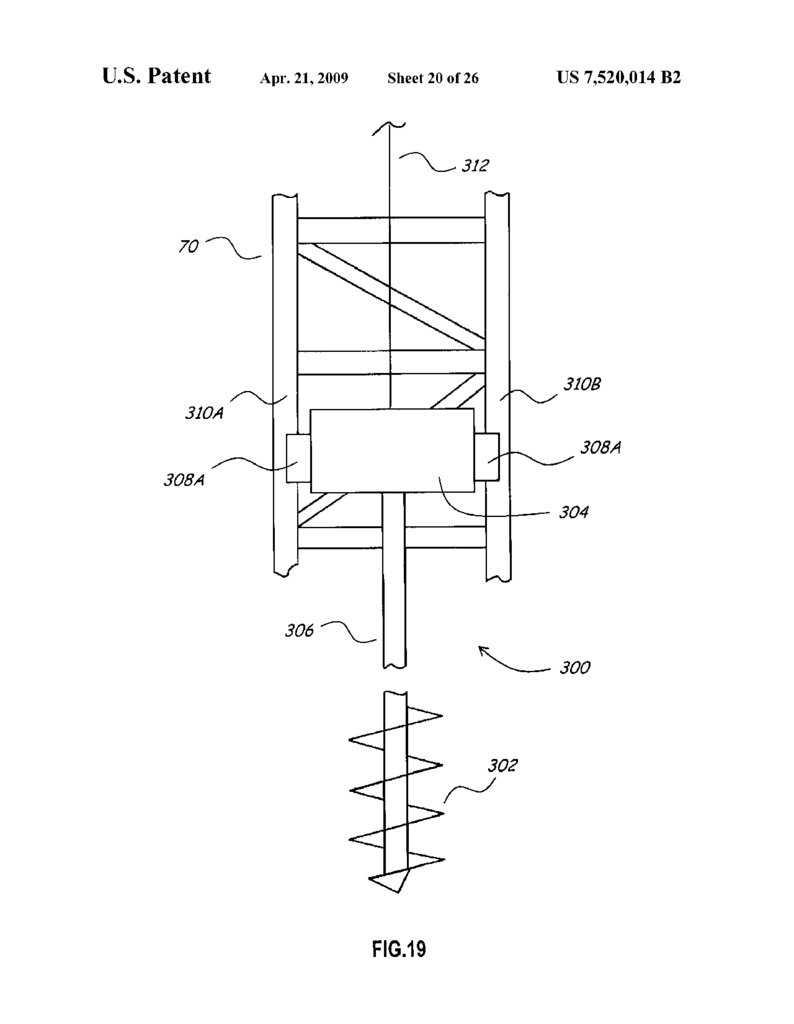
FIG. 19 illustrates a portion of a lead assembly that
girder, i.e. a girder that is used is the outer-most lateral girder
in a bridge. The pre-cast edge girder is comprised of a later includes a drill for excavating a hole for a pile, concrete
ally extending portion and an vertical extending portion that 65 drilled shaft, or similar structure;
is operatively connected to the laterally extending portion
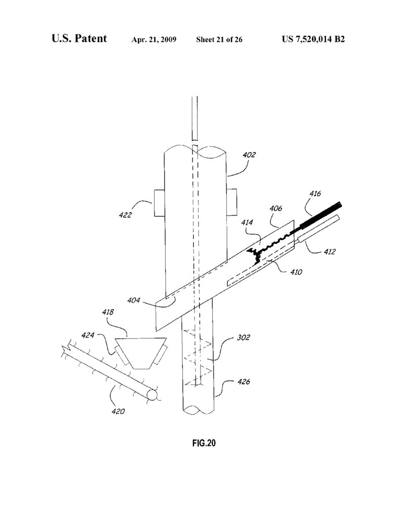
FIG. 20 illustrates a system for the removal of drill tailings
thereby forming an L-shaped edge girder. Since the L-shaped produced by the operation of the drill illustrated in FIG. 19:
30.
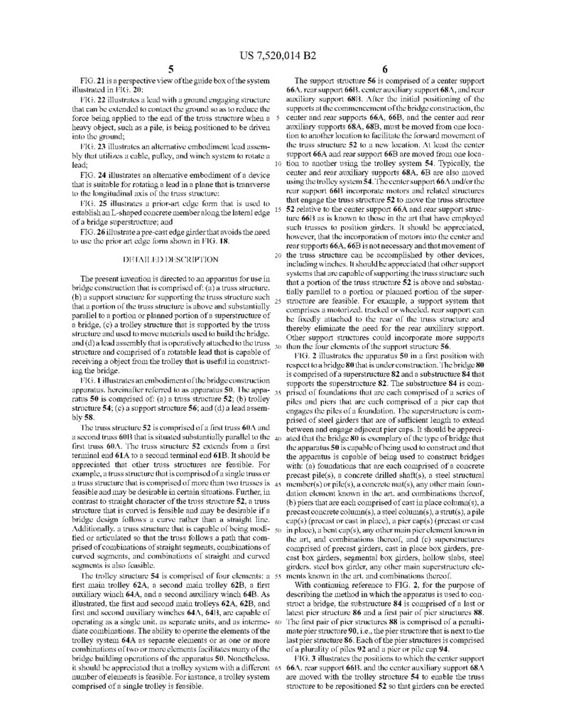
US 7,520,014 B26
The support structure 56 is comprised of a center support
66A, rear support 66B, center auxiliary support 68A, and rear
illustrated in FIG. 20;
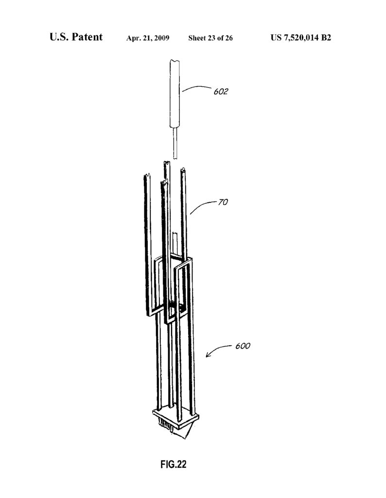
FIG.22 illustrates a lead with a ground engaging structure auxiliary support 68B. After the initial positioning of the
that can be extended to contact the ground so as to reduce the Supports at the commencement of the bridge construction, the
force being applied to the end of the truss structure when a 5 center and rear supports 66A, 66B, and the center and rear
heavy object, Such as a pile, is being positioned to be driven auxiliary supports 68A, 68B, must be moved from one loca
tion to another location to facilitate the forward movement of
into the ground;
5
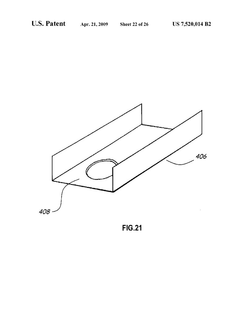
FIG.21 is a perspective view of the guide box of the system
the truss structure 52 to a new location. At least the center
FIG. 23 illustrates an alternative embodiment lead assem
support 66A and rear support 66B are moved from one loca
tion to another using the trolley system 54. Typically, the
center and rear auxiliary supports 68A, 6B are also moved
FIG. 24 illustrates an alternative embodiment of a device
that is suitable for rotating a lead in a plane that is transverse using the trolley system54. The center support 66A and/or the
rear support 66B incorporate motors and related structures
to the longitudinal axis of the truss structure;
that
engage the truss structure 52 to move the truss structure
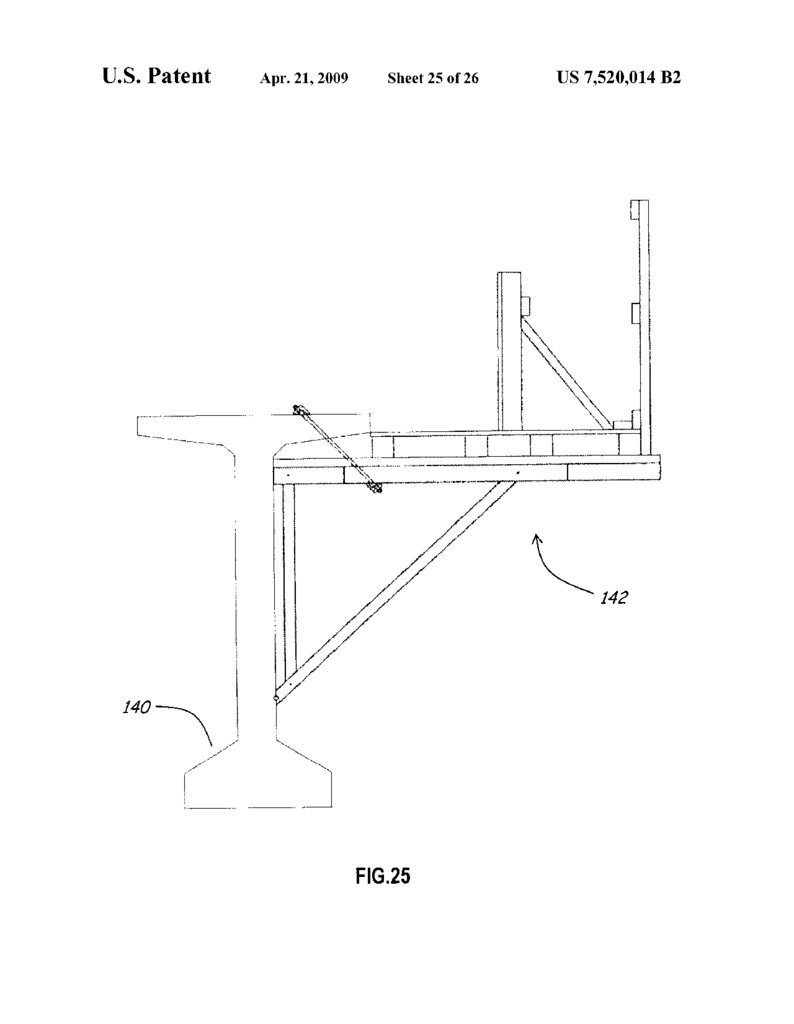
FIG. 25 illustrates a prior-art edge form that is used to
establish an L-shaped concrete member along the lateral edge 15 52 relative to the center support 66A and rear support struc
ture 66B as is known to those in the art that have employed
of a bridge Superstructure; and
Such trusses to position girders. It should be appreciated,
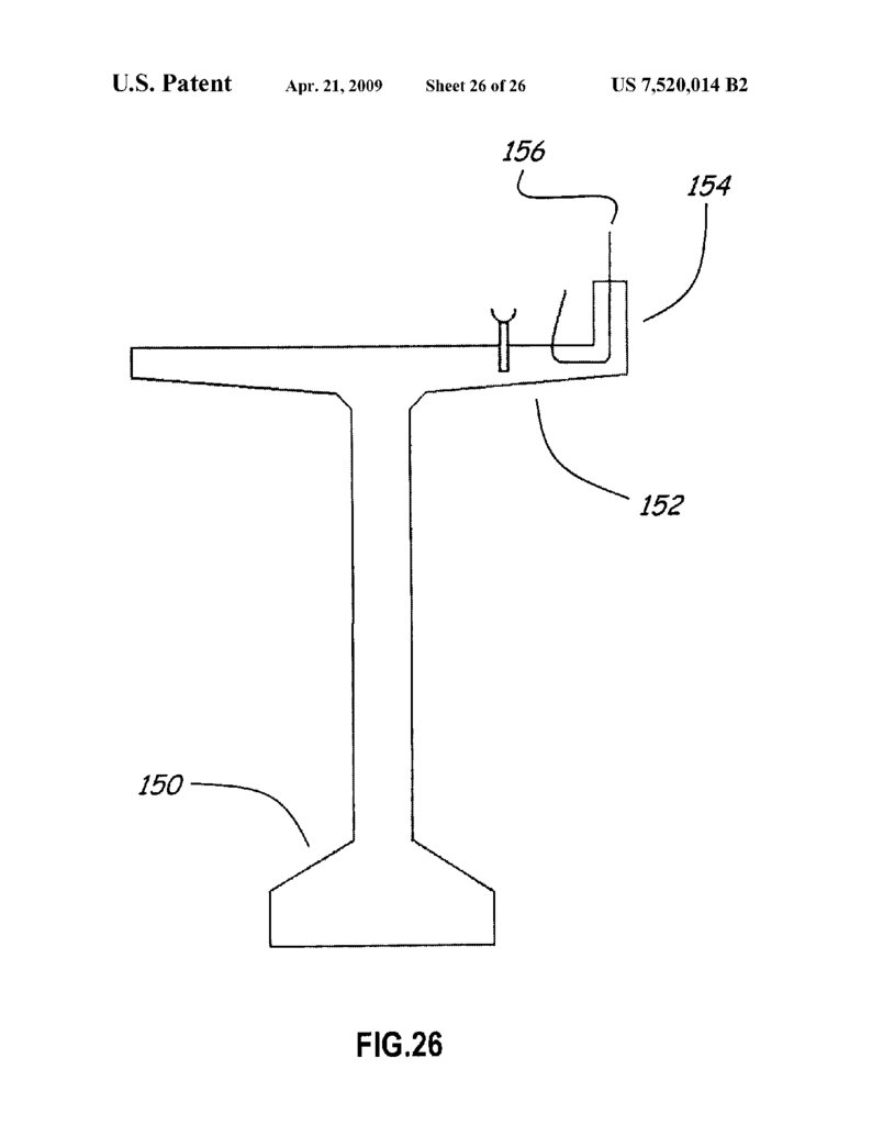
FIG. 26 illustrate a pre-cast edge girder that avoids the need however,
that the incorporation of motors into the center and
to use the prior art edge form shown in FIG. 18.
rear supports 66A, 66B is not necessary and that movement of
the truss structure can be accomplished by other devices,
DETAILED DESCRIPTION
including winches. It should be appreciated that other Support
systems that are capable of supporting the truss structure Such
The present invention is directed to an apparatus for use in that a portion of the truss structure 52 is above and substan
bridge construction that is comprised of: (a) a truss structure, tially parallel to a portion or planned portion of the Super
(b) a Support structure for Supporting the truss structure Such 25 structure are feasible. For example, a Support system that
that a portion of the truss structure is above and substantially comprises a motorized, tracked or wheeled, rear Support can
parallel to a portion or planned portion of a Superstructure of be fixedly attached to the rear of the truss structure and
a bridge, (c) a trolley structure that is Supported by the truss thereby eliminate the need for the rear auxiliary support.
structure and used to move materials used to build the bridge, Other Support structures could incorporate more Supports
and (d) a lead assembly that is operatively attached to the truss than the four elements of the support structure 56.
structure and comprised of a rotatable lead that is capable of
FIG. 2 illustrates the apparatus 50 in a first position with
receiving a object from the trolley that is useful in construct respect
to a bridge 80that is under construction. The bridge 80
ing the bridge.
is comprised of a superstructure 82 and a substructure 84 that
FIG. 1 illustrates an embodiment of the bridge construction supports the superstructure 82. The substructure 84 is com
apparatus, hereinafter referred to as apparatus 50. The appa 35 prised of foundations that are each comprised of a series of
ratus 50 is comprised of: (a) a truss structure 52; (b) trolley piles and piers that are each comprised of a pier cap that
structure 54; (c) a support structure 56; and (d) a lead assem engages the piles of a foundation. The Superstructure is com
bly 58.
prised of steel girders that are of sufficient length to extend
The truss structure 52 is comprised of a first truss 60A and between and engage adjacent pier caps. It should be appreci
a second truss 60B that is situated substantially parallel to the 40 ated that the bridge 80 is exemplary of the type of bridge that
first truss 60A. The truss structure 52 extends from a first
the apparatus 50 is capable of being used to construct and that
terminal end 61A to a second terminal end 61B. It should be
the apparatus is capable of being used to construct bridges
appreciated that other truss structures are feasible. For with: (a) foundations that are each comprised of a concrete
example, a truss structure that is comprised of a single truss or precast pile(s), a concrete drilled shaft(s), a steel structural
a truss structure that is comprised of more than two trusses is 45 member(s) or pile(s), a concrete mat(s), any other main foun
feasible and may be desirable in certain situations. Further, in dation element known in the art, and combinations thereof,
contrast to straight character of the truss structure 52, a truss (b) piers that are each comprised of cast in place column(s), a
structure that is curved is feasible and may be desirable if a precast concrete column(s), a steel column(s), a strut(s), a pile
bridge design follows a curve rather than a straight line. cap(s) (precast or cast in place), a pier cap(s) (precast or cast
Additionally, a truss structure that is capable of being modi 50 in place), a bent cap(S), any other main pier element known in
fied or articulated so that the truss follows a path that com the art, and combinations thereof, and (c) Superstructures
prised of combinations of straight segments, combinations of comprised of precast girders, cast in place box girders, pre
curved segments, and combinations of straight and curved cast box girders, segmental box girders, hollow slabs, steel
segments is also feasible.
girders, steel box girder, any other main Superstructure ele
The trolley structure 54 is comprised of four elements: a 55 ments known in the art, and combinations thereof.
With continuing reference to FIG. 2, for the purpose of
first main trolley 62A, a second main trolley 62B, a first
auxiliary winch 64A, and a second auxiliary winch 64B. As describing the method in which the apparatus is used to con
illustrated, the first and second main trolleys 62A, 62B, and struct a bridge, the substructure 84 is comprised of a last or
first and second auxiliary winches 64A, 64B, are capable of latest pier structure 86 and a first pair of pier structures 88.
operating as a single unit, as separate units, and as interme 60 The first pair of pier structures 88 is comprised of a penulti
diate combinations. The ability to operate the elements of the mate pier structure 90, i.e., the pier structure that is next to the
trolley System 64A as separate elements or as one or more last pier structure 86. Each of the pier structures is comprised
combinations of two or more elements facilitates many of the of a plurality of piles 92 and a pier or pile cap 94.
bridge building operations of the apparatus 50. Nonetheless,
FIG.3 illustrates the positions to which the center support
it should be appreciated that a trolley system with a different 65 66A, rear support 66B, and the center auxiliary support 68A
number of elements is feasible. For instance, a trolley system are moved with the trolley structure 54 to enable the truss
comprised of a single trolley is feasible.
structure to be repositioned 52 so that girders can be erected
bly that utilizes a cable, pulley, and winch system to rotate a
lead;
10
31.
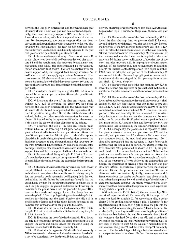
US 7,520,014 B27
8
between the lead pier structure 86 and the penultimate pier delivery of a first pier cap form or pre-cast shell 122A that will
structure 90 and a new lead pier can be established. Specifi be placed on top of a number of the piles of the new lead pier
cally, the center auxiliary supports 68A have been moved 120.
forward to a location just behind the penultimate pier struc
FIG. 13 illustrates the use of the first main trolley 62A to
ture 90. Subsequently, the center support 66A has been 5 lower the first pier cap form or pre-cast shell 122A onto
moved from the penultimate pier structure 90 to the lead pier several of the piles of the new lead pier structure 120. Prior to
structure 86. Subsequently, the rear support 66B has been the lowering of the first pier cap form or pre-cast shell 122A
moved forward to a location Substantially adjacent to the pier onto the piles, the hammer associated with the lead assembly
that precedes the penultimate pier structure 90.
58 was removed from the lead assembly 58. The removal of
FIG. 4 illustrates the repositioning of the truss structure 52 10 the hammer reduces the force that is applied to the truss
so that girders can be established between the lead pier struc structure 54 during the establishment of the pier cap of the
ture 86 and the penultimate pier structure 90 and a new lead new lead pier structure 120. In appropriate circumstances,
pier can be established. The truss structure 52 is moved using removal of the hammer may not be necessary. In addition,
motor assemblies (not shown) that are associated with the prior to the lowering of the first pier cap form or pre-cast shell
center support 66A, rear support 66B, trolley structure 54, 15 122A onto the piles, the lead portion of the lead assembly 58
and/or an external force applying structure. Movement of the was rotated into the illustrated upright position so as not to
truss structure 52 also repositions the center auxiliary Sup interfere with the lowering of the first pier cap form or pre
ports 68A immediately behind the center support 66A and the cast shell 122A onto the piles.
rear auxiliary supports 68E3 immediately behind the rear Sup
FIG. 14 illustrates the use of the first main trolley 62A to
port 66B.
lower the second pier cap form or pre-cast shell 122B onto a
FIG. 5 illustrates the delivery of a girder 100 that is to be number of the piles associated with the new lead pier structure
erected between lead pier structure 86 and the penultimate 120.
pier structure 90.
FIG. 15 illustrates the use of the first main trolley 62A to
FIG. 6 illustrates the use of the first and second main
lower rebar and/or cement into the cap form or pre-cast shell
trolleys 62A, 62B in lowering the girder 100 into place 25 created by the first and second pier cap forms or pre-cast
between the lead pier structure 86 and the penultimate pier shells 122A, 122B, thereby establishing the cap 94 of the now
structure 90. As should be appreciated, the apparatus 50 is completed, new lead pier structure 120. At this point, the lead
used to position the girder 100 but the establishment of a portion of the lead assembly 58 can be rotated to a substan
tially horizontal position so that the hammer can be reat
welded, bolted, or other suitable connection between the
girder 100 is not done by the apparatus 50 but by other means. 30 tached to the assembly 58. Further, upon repositioning the
first main trolley 62A and the first auxiliary trolley 64A, the
This is also the case with other elements of the bridge.
FIG. 7 illustrates the use of the first and second main
apparatus 50 is in substantially the same orientation as shown
trolleys 62A, 62B in lowering a final girder of a plurality of in FIG. 2. Consequently, the process can be repeated to estab
girders that extend between the lead pier structure 86 and the lish girders between the new lead pier structure 120 and the
penultimate pier structure 90 into place. It should be appre 35 now old, lead pier structure 82 and to establish a newer lead
ciated that in establishing the plurality of girders between the pier structure beyond the new lead pier structure 120. It
should be appreciated that the sequence of steps followed in
lead pier structure 86 and the penultimate pier structure 90.
the truss structure 52 moves laterally. The lateral movement is constructing the bridge can be varied. For example, after the
accomplished by motor assemblies associated with the center truss structure 52 is positioned as shown in FIG. 4, the piles
support 66A and the rear support 66B as is known in the art. 40 could be driven for the new lead pier structure 120 before the
FIG. 8 illustrates the delivery of a pile 110 that will be part girders are erected between the lead pier structure 86 and the
of a new lead pier structure that the apparatus 50 will be used penultimate pier structure 90. As another example of a varia
to establish at a location beyond the current lead pier structure tion in the sequence of steps followed in constructing the
86.
bridge, the operations of driving a pile for the new lead pier
FIG.9 illustrates the use of the trolley structure 54 to lower 45 structure 120 and the erection of a girder between the lead pier
the pile 110 onto the lead assembly 58, which in the illustrated structure 86 and the penultimate pier structure 90 can be
embodiment comprises a hammer for use in driving the pile alternated with one another. Typically, there are several dif
into the ground, a guide system for holding the pile in the lead ferent operations that can be performed at any given point in
and guiding the pile during the hammering of the pile into the time using the apparatus 50 with the timing of the delivery of
ground, and a winch for lowering the hammer and the pile 110 50 elements needed to construct the bridge typically being deter
until the pile engages the ground and thereafter lowering the minative of the operation that the apparatus is used to perform
hammer as the pile is driven into the ground. The pile 110 is at any particular point in time.
received by a guide and engaged by a collar clamp that pre
With reference to FIGS. 16A-C, the lead assembly 58 is
vents the pile 110 from slipping during rotation of the pile into described in greater detail. The assembly 58 is comprised of
position for driving into the earth. Further, the pile 110 is 55 a truss or lead 70, a guide 72 for receiving a pile, a collar
positioned so that an end of the pile is located adjacent to the clamp 74 for guiding and gripping a pile, a hammer 76 for
repeated striking of one end of a pile to drive the pile into the
hammer that is used to drive the pile into the earth.
FIG. 10 illustrates the use of the lead assembly 58 to rotate earth, a cord 78 for connecting the collar 74 to the hammer 76,
the pile 110 into a position that is suitable for driving the pile a cable/pulley/winch system 80 for controlling the position of
110 into the earth.
60 the hammer 76 relative to the lead 70, a two-axis pivotjoint 82
FIG. 11 illustrates the use of the lead assembly 58 to lower that connects the lead 70 to the truss 52, and a hydraulic
the pile 110 to the point at which the distal end of the pile 110 system 84 for rotating the lead 70 about the pivot joint 82. The
engages the earth and can be driven into the earth using the two axes of the pivot joint 82 are typically perpendicular to
one another. The guide 72 and the collar clamp 74 preferably
hammer associated with the lead assembly 58.
FIG. 12 illustrates the apparatus 50 after the lead assembly 65 are each of a clam-shell type of design that allows two halves
58 has been used to drive several piles that are associated with to be separated so as to receive a pile from the trolley structure
a yet to be completed, new lead pier 120 into the earth and the 54.
32.
US 7,520,014 B29
10
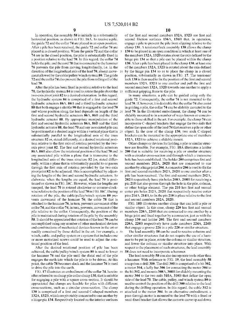
In operation, the assembly 58 is initially in a substantially of the first and second members 132A, 132B are first and
horizontal position, as shown in FIG.16A. To receive a pile,
second friction surfaces 136A, 136B that, in operation,
the guide 72 and the collar 74 are placed in an open position. engage a pile to prevent the pile from slipping relative to the
After a pile has been received, the guide 72 and collar 74 are clamp 130. A tensioner/lock assembly 138 allows the clamp
placed in a closed position. When the guide 72 and the collar 5 130 to be placed in an open condition in which at least one of
74 are in the closed position, the pile is substantially fixed in the members 132A, 132B rotates about the axis defined by the
a position relative to the lead 70. In this regard, the collar 74 hinge pin 134 So that a pile can be placed within the clamp
holds the pile, and the cord 78 that is connected to the hammer 130. After a pile has been placed in the clamp 130, at least one
76 prevents the pile from moving longitudinally, i.e. in the of the members 132A, 132B is rotated about the axis defined
direction of the longitudinal axis of the lead 70, absent move 10 by the hinge pin 134 So as to place the clamp in a closed
mentallowed by the cable/pulley/winch system 80. The guide position, substantially as shown in FIG. 17. The tensioner/
72 and the collar 74 also prevent the pile from rolling off of the lock 138 is then used to fix the position of the first and second
lead 70.
members 132A, 132B to one another and pull the first and
After the pile has been fixed in position relative to the lead second members 132A, 132B towards one another to apply a
70, the hydraulic system 84 is used to rotate the pile about the 15 Sufficient gripping force to the pile.
In many situations, a pile can be guided using only the
two-axis pivot joint 82 to a desired orientation. In this regard,
the hydraulic system 84 is comprised of a first and second guide 72. Consequently, the collar 74 is not mounted to the
hydraulic actuators 86A, 86B and a third hydraulic actuator lead 70. If, however, it is desirable that the collar 74 also assist
88 that both engage a shuttle 90 that is engaged to the lead 70 in guiding a pile, the collar 74 can be slidably mounted to the
and whose position along the lead depends on length of the lead 70. In the illustrated embodiment, the clamp 74 can be
first and second hydraulic actuators 86A, 86B and the third slidably mounted to in a number of ways known or conceiv
hydraulic actuator 88. By appropriate manipulation of the able to those skilled in the art. For example, the clamp 74 can
first and second hydraulic actuators 86A, 86B and the third incorporate C-shaped brackets that engage the two rails that
hydraulic actuator 88, the lead 70 and any associated pile can define the open side of the lead 74 that receives a pile or other
be positioned at a desired angle within a vertical plane that is 25 object. In the case of the clamp 130, two such C-shaped
substantially parallel to the longitudinal axis of the truss brackets can be mounted to the appropriate one of members
structure 52 or, stated differently, at a desired rotational posi 132A, 132B to achieve a slidable mount.
Other clamps or devices for holding a pile or similar struc
tion relative to the first axis of rotation provided by the two
axis pivot joint 82. The first and second hydraulic actuators ture are feasible. For example, FIG. 18A illustrates a holder
86A, 86B also allow the rotational position of the lead 70 and 30 200 that is suitable for receiving a pile or similar structure
any associated pile within a plane that is transverse to the with a circular cross-section and through which a transverse
longitudinal axis of the truss structure 52 (or, stated differ hole has been established. The holder 200 comprises first and
ently, within a plane that is Substantially parallel to or passes second members 202A, 202B that are connected to one
through the first axis of rotation provided by the two-axis another by a hingejoint 204. A connector 206 is used to fix the
pivot joint 82) to be adjusted. This is accomplished by adjust 35 first and second members 202A, 202B to one another after a
ing the lengths of the first and second hydraulic actuators. To pile has been received. The first and second members 202A,
elaborate, when the lengths are equal, the lead 70 is posi 202B respectively have pinholes 208A, 208B for receiving a
tioned as shown in FIG. 16C. However, when the lengths are pin 210 that also passes through the hole in the pile, column,
unequal, the lead 70 is rotated clockwise or counter-clock or other bridge element. The pin 210 has first and second
wise relative to the position of the lead 70 in FIG.16C. During 40 cotter pin holes 212A, 212B that respectively receive cotter
rotation of the pile, the cable/pulley/winch system 80 pre pins 214A, 214B, to fix the pin 210 in place relative to the first
vents movement of the hammer 76; the cable 78 that is
and second members 202A, 202B.
FIG. 18B illustrates another clamp that can hold a pile or
attached to the hammer 76, in turn, prevents movement of the
collar 74; and the collar 74, in turn, prevents, movement of the similar object. In this case, clamp 220 has first and second
pile relative to the collar. Consequently, the position of the 45 members 220A, 220B that are connected to one another by a
pile is maintained during rotation of the pile by the assembly hinge joint and fixed together by a connector, just as with the
58. It should be appreciated that rotation of the lead 70 can be clamp 130 and holder 200. The first and second members
accomplished using any number of other mechanical devices 220A, 220B respectively have male members 224A, 224B
and combinations of mechanical devices known in the art or
that engage a groove 226 in a pile 228 or similar structure.
readily conceived by those skilled in the art. For example, a 50 The lead assembly 58 can be used to receive columns and
winch, cable, and pulley System or a system that includes one other similar structures that do not require the use of a ham
or more motorized screws could be used to adjust the rota merto be put in place, rotate the column or similar structure,
tional position of the lead.
and lower the column or similar structure into place. With
After the desired rotational position of pile has been respect to the placement of such structures, the lead assembly
achieved, the cable/pulley/winch system 80 is used to lower 55 58 does not need to incorporate a hammer.
The lead assembly 58 can also incorporate tools other than
the hammer 76 and the pile until the distal end of the pile
engages the earth into which the pile is to be driven. At this a hammer. With reference to FIG. 19, the lead assembly 58
point, the cable 78 becomes slack and the hammer 76 is used comprises a drill 300. The drill 300 is comprised of a bit 302,
a motor 304, a kelly bar 306 for connecting the motor 304 to
to drive the pile into the earth.
FIG. 17 illustrates an embodiment of the collar 74, herein 60 the bit 302, and mounts 308A,308B for slidably mounting the
after referred to as clamp pile collar clamp 130, that is suitable motor 304 to the two rails 310A, 310B that define the open
for engaging a pile with a square cross-section. It should be side of the lead 70. The cable, pulley, and winch system 80 is
appreciated that clamps are feasible for piles with different used to control the position of the drill 300 relative to the lead
cross-sections, such as a circular cross-section. The clamp during the drilling operation. In this regard, the cable 312 is
130 is comprised of a first and second C-shaped members 65 attached to the motor 304. In an alternative embodiment, a
132A, 132B, which are pivotably connected to one another by pass-through motor is mounted to the lead 70 with a fixed or
a hinge pin 134. Respectively located on the interior surfaces semi-fixed bracket that allows the motor to move up and down
33.
US 7,520,014 B211
the lead for a limited distance. The Kelly bar and drill bit are
Suspended using the winch and cable. The motor is designed
to allow the kelly bar to pass through an opening that is
designed to transfer torque from the motor to the Kelly bar
and the drill bit.
12
to lower the drill until the drill bit 302 engages the ground.
Typically, the drill 300 is activated to begin rotating the drill
bit 302 before the bit engages the ground. Excavation com
mences when the drill bit 302 has engaged the ground and the
drill 300 has been activated. The weight of the motor 304 and
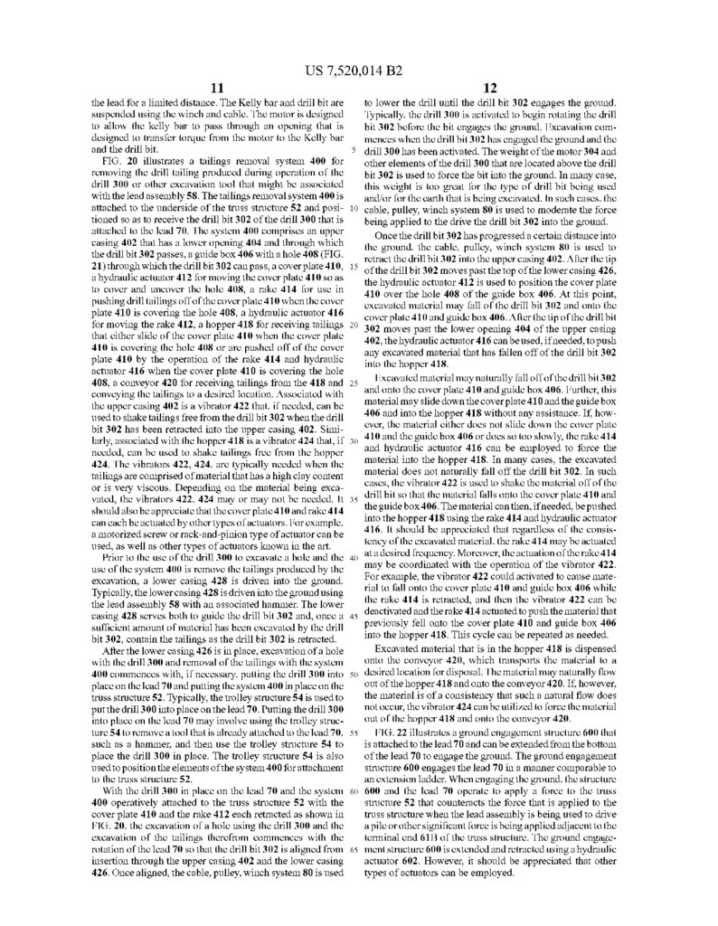
FIG. 20 illustrates a tailings removal system 400 for other elements of the drill 300 that are located above the drill
removing the drill tailing produced during operation of the bit 302 is used to force the bit into the ground. In many case,
drill 300 or other excavation tool that might be associated this weight is too great for the type of drill bit being used
with the lead assembly 58. The tailings removal system 400 is and/or for the earth that is being excavated. In Such cases, the
attached to the underside of the truss structure 52 and posi 10 cable, pulley, winch system 80 is used to moderate the force
tioned so as to receive the drill bit 302 of the drill 300 that is
being applied to the drive the drill bit 302 into the ground.
attached to the lead 70. The system 400 comprises an upper
the drill bit 302 has progressed a certain distance into
casing 402 that has a lower opening 404 and through which theOnce
ground, the cable, pulley, winch system 80 is used to
the drill bit 302 passes, a guidebox 406 with a hole 408 (FIG. retract the drill bit 302 into the upper casing 402. After the tip
21) through which the drill bit 302 can pass, a cover plate 410. 15 of the drill bit 302 moves past the top of the lower casing 426,
a hydraulic actuator 412 for moving the cover plate 410 so as the hydraulic actuator 412 is used to position the cover plate
to cover and uncover the hole 408, a rake 414 for use in
over the hole 408 of the guide box 406. At this point,
pushing drill tailings off of the cover plate 410 when the cover 410
material may fall of the drill bit 302 and onto the
plate 410 is covering the hole 408, a hydraulic actuator 416 excavated
cover
plate
and guide box 406. After the tip of the drill bit
for moving the rake 412, a hopper 418 for receiving tailings 302 moves 410
past the lower opening 404 of the upper casing
that either slide of the cover plate 410 when the cover plate 402, the hydraulic actuator 416 can be used, if needed, to push
410 is covering the hole 408 or are pushed off of the cover any excavated material that has fallen off of the drill bit 302
plate 410 by the operation of the rake 414 and hydraulic into the hopper 418.
actuator 416 when the cover plate 410 is covering the hole
408, a conveyor 420 for receiving tailings from the 418 and 25 Excavated material may naturally fall off of the drill bit 302
the cover plate 410 and guide box 406. Further, this
conveying the tailings to a desired location. Associated with and onto may
slide down the coverplate 410 and the guidebox
the upper casing 402 is a vibrator 422 that, if needed, can be material
406
and
into
the
418 without any assistance. If, how
used to shake tailings free from the drill bit 302 when the drill ever, the materialhopper
either does not slide down the cover plate
bit 302 has been retracted into the upper casing 402. Simi 410 and the guide box
or does so too slowly, the rake 414
larly, associated with the hopper 418 is a vibrator 424 that, if 30 and hydraulic actuator406
416 can be employed to force the
needed, can be used to shake tailings free from the hopper
424. The vibrators 422, 424, are typically needed when the material into the hopper 418. In many cases, the excavated
tailings are comprised of material that has a high clay content material does not naturally fall off the drill bit 302. In such
or is very viscous. Depending on the material being exca cases, the vibrator 422 is used to shake the material off of the
drill bit so that the material falls onto the cover plate 410 and
vated, the vibrators 422, 424 may or may not be needed. It 35 the
406. The material can then, if needed, be pushed
should also be appreciate that the cover plate 410 and rake 414 intoguidebox
hopper 418 using the rake 414 and hydraulic actuator
can each be actuated by other types of actuators. For example, 416. the
It should be appreciated that regardless of the consis
a motorized screw or rack-and-pinion type of actuator can be
tency
of the excavated material, the rake 414 may be actuated
used, as well as other types of actuators known in the art.
at
a
desired
frequency. Moreover, the actuation of the rake 414
Prior to the use of the drill 300 to excavate a hole and the 40
use of the system 400 is remove the tailings produced by the may be coordinated with the operation of the vibrator 422.
For example, the vibrator 422 could activated to cause mate
excavation, a lower casing 428 is driven into the ground. rial
to fall onto the cover plate 410 and guide box 406 while
Typically, the lower casing 428 is driven into the ground using
the
rake
414 is retracted, and then the vibrator 422 can be
the lead assembly 58 with an associated hammer. The lower deactivated
and the rake 414 actuated to push the material that
casing 428 serves both to guide the drill bit 302 and, once a 45 previously fell
the cover plate 410 and guide box 406
sufficient amount of material has been excavated by the drill into the hopper onto
418. This cycle can be repeated as needed.
bit 302, contain the tailings as the drill bit 302 is retracted.
Excavated material that is in the hopper 418 is dispensed
After the lower casing 426 is in place, excavation of a hole
with the drill 300 and removal of the tailings with the system onto the conveyor 420, which transports the material to a
400 commences with, if necessary, putting the drill 300 into 50 desired location for disposal. The material may naturally flow
place on the lead 70 and putting the system 400 in place on the out of the hopper 418 and onto the conveyor 420. If, however,
truss structure 52. Typically, the trolley structure 54 is used to the material is of a consistency that such a natural flow does
not occur, the vibrator 424 can be utilized to force the material
put the drill300 into place on the lead 70. Putting the drill 300
into place on the lead 70 may involve using the trolley struc out of the hopper 418 and onto the conveyor 420.
ture 54 to remove a tool that is already attached to the lead 70, 55 FIG.22 illustrates a ground engagement structure 600 that
such as a hammer, and then use the trolley structure 54 to is attached to the lead 70 and can be extended from the bottom
place the drill 300 in place. The trolley structure 54 is also of the lead 70 to engage the ground. The ground engagement
used to position the elements of the system 400 for attachment structure 600 engages the lead 70 in a manner comparable to
to the truss structure 52.
an extension ladder. When engaging the ground, the structure
With the drill 300 in place on the lead 70 and the system 60 600 and the lead 70 operate to apply a force to the truss
400 operatively attached to the truss structure 52 with the structure 52 that counteracts the force that is applied to the
cover plate 410 and the rake 412 each retracted as shown in truss structure when the lead assembly is being used to drive
FIG. 20, the excavation of a hole using the drill 300 and the a pile or other significant force is being applied adjacent to the
excavation of the tailings therefrom commences with the terminal end 61B of the truss structure. The ground engage
rotation of the lead 70 so that the drill bit 302 is aligned from 65 ment structure 600 is extended and retracted using a hydraulic
insertion through the upper casing 402 and the lower casing actuator 602. However, it should be appreciated that other
426. Once aligned, the cable, pulley, winch system 80 is used types of actuators can be employed.
34.
US 7,520,014 B213
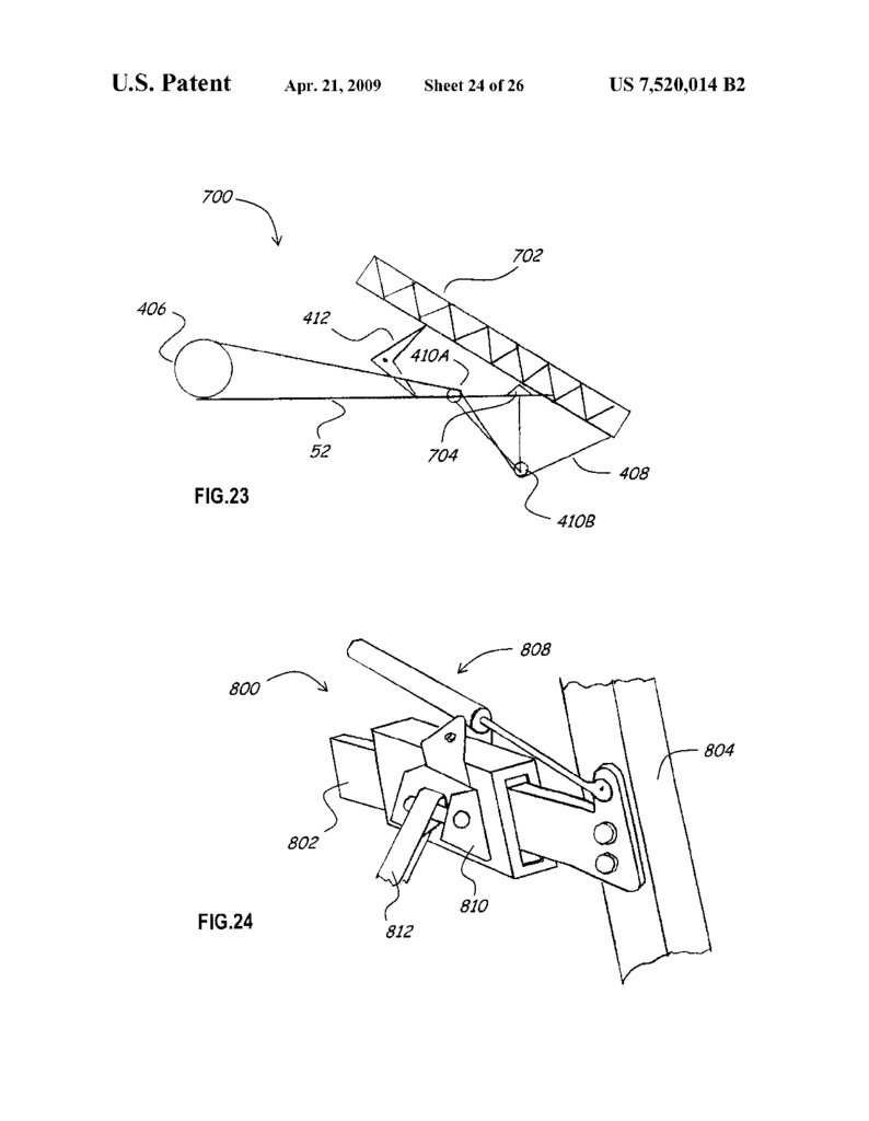
FIG. 23 schematically illustrates a second embodiment of
a lead assembly 700 that comprises a lead 702, a two-axis
pivot joint 704 for connecting the lead 702 to the truss struc
14
with the construction of a bridge, and movable between
ture 52, a winch 406, a cable 408 that extends from the winch
a lead assembly that, in operation, is operatively attached to
said truss structure and comprises a lead, a pivot joint for
pivotally connecting said lead to said truss structure Such
said first and second terminal ends of said truss struc
ture;
406 to the lead 702, and a pair of pulleys 410A, 410B that
guide the cable 408, a hinged resistive element 412 that mod
erates the rotation of the lead 702 caused by the winch 406.
The hinged resistive element 412 provides resistance by uti
lizing a hydraulic element. It should be appreciated that the
other resistive elements are feasible, including elements that 10
are nothinged. In operation, the winch 406 and cable 408 are
used to move the lead 702 to a desired rotational position
about an axis that is transverse to the longitudinal axis of the
truss structure. The hinged resistive element 412 moderates
15
the rotational operation.
FIG.24 illustrates a second embodimentofa device 800 for
use in causing the lead to rotate in a plane that is transverse to
the longitudinal axis of the truss structure 52. The device 800
comprises a curved plate 802 that is fixed to a lead 804, a
slotted box 806 that receives the plate 802, a hydraulic actua
tor 808 with a cylinder that is pivotally attached to the slotted
box 806 and a rod that is pivotally and operatively attached to
the lead 804, and a pivot attachment 810 for a support 812 that
is attached to the truss structure 52 and not readily susceptible
to rotation about the longitudinal axis of the truss structure 52. 25
In operation, the hydraulic actuator 808 is used to apply a
force to the lead 804 that causes the lead to move relative to
30
barrier, such as a fence.
associated with said lead.
3. An apparatus, as claimed in claim 1, wherein:
said pivot joint allows said lead to pivot about a first axis.
4. An apparatus, as claimed in claim 1, wherein:
said pivotjoint is a two-axis pivot joint that allows said lead
to pivot about a first axis and to pivot about a second axis
axis.
6. An apparatus, as claimed in claim 1, wherein:
said actuating system comprises an actuator.
7. An apparatus, as claimed in claim 1, wherein:
said actuating system comprises a first actuator and a sec
ond actuator.
8. An apparatus, as claimed in claim 1, wherein:
said actuating system comprises a first actuator, a second
actuator, and a third actuator.
FIG. 26 illustrates a girder 150 that is used in a bridge
superstructure as the outer-most girder. The girder 150 is 40
pre-cast so as to have a laterally extending portion 152 and a
vertically extending portion 154 that is operatively connected
t to the laterally extending portion so as to forman L-shaped
edge that is useful for containing concrete or other fluid
material that is poured on top of the girder to establish the 45
superstructure deck. If desired rebar 156 can be incorporated
into the vertically extending portion 154 of the girder. It shod
be appreciated that the edge can be other shapes that serve the
various purposes for which an edge is used on a bridge Super
50
The embodiments of the invention described above are
intended to describe the best mode known of practicing the
invention and to enable others skilled in the art to utilize the
invention.
What is claimed is:
55
1. An apparatus for use in constructing a bridge comprised
of a substructure having two or more piers and a SuperStruc
ture that is Supported by the Substructure, the apparatus com
prising:
a truss structure that extends from a first terminal end to a 60
second terminal end;
the lead is rotated about said axis;
wherein, when said lead assembly is in a first position, said
lead is capable of receiving an object from said trolley.
2. An apparatus, as claimed in claim 1, wherein:
when said lead is in said first position, said trolley is
capable of positioning an object above said lead and
lowering said object so that said object can become
5. An apparatus, as claimed in claim 4, wherein:
said first axis is Substantially perpendicular to said second
FIG.25 illustrates a girder 140 that is the outer-most lateral
girder of a bridge superstructure and the form 142 that must
be attached to the girder 140 to create an L-shaped edge that
is attached to the girder 140. The L-shaped edge serves t
contain concrete or other fluid material that is poured on top 35
of the girder to establish the superstructure deck. In addition,
the L-shaped edge provides a Surface for attaching a lateral
Structure.
stantially parallel to a portion or planned portion of a
superstructure of a bridge and rotated between a sub
stantially horizontal position and a substantially vertical
position, an actuating system for causing said lead to
pivot to a desired rotational position, and securing
device for holding an object adjacent to said lead when
that is different than said first axis.
the slotted box 810 and, more specifically, to rotate in a plane
that is transverse to the longitudinal axis of the truss structure
52.
that said lead can be rotated about an axis that is Sub
a Support structure for, in operation, Supporting said truss
structure Such that a portion of said truss structure is
above and Substantially parallel to a portion or planned
65
portion of a SuperStructure of a bridge;
a trolley that, in operation, is operatively attached to said
truss structure, capable of hoisting an object associated
9. An apparatus, as claimed in claim 1, wherein:
said actuating system comprises a hydraulic actuator.
10. An apparatus, as claimed in claim 1, wherein:
said trolley comprising a first trolley portion and a second
trolley portion that is separate from said first trolley
portion.
11. An apparatus, as claimed in claim 10, wherein:
said first trolley portion comprises a first hoist and said
second trolley portion comprises a second hoist.
12. An apparatus, as claimed in claim 1, wherein:
said lead assembly comprises a pile hammer operatively
connected to said lead.
13. An apparatus, as claimed in claim 1, wherein:
said lead assembly comprises a drill operatively connected
to said lead.
14. An apparatus, as claimed in claim 1, wherein:
said trolley is capable of moving a SuperStructure element
to a desired location in a bridge and a substructure ele
ment to either a desired location in a bridge or a position
from which the substructure element can be moved to a
desired location in a bridge.
15. An apparatus for use in constructing a bridge comprised
of a substructure having two or more piers and a Superstruc
ture that is Supported by the Substructure, the apparatus com
prising:
a truss structure that extends from a first terminal end to a
second terminal end;
a Support structure for, in operation, Supporting said truss
structure Such that a portion of said truss structure is
35.
US 7,520,014 B215
above and Substantially parallel to a portion or planned
portion of a SuperStructure of a bridge;
a trolley that, in operation, is operatively attached to said
truss structure, capable of hoisting an object associated
with the construction of a bridge, and movable between 5
said first and second terminal ends of said truss struc
ture;
a lead assembly that, in operation, is operatively attached to
said truss assembly, said lead assembly comprising:
a lead:
10
a two-axis pivot joint for connecting said lead to said
truss structure and allowing said lead to be rotated
about a first axis and about a second axis that is dif
ferent than said first axis, and allowing said lead to be
rotated between a substantially horizontal position 15
and a Substantially vertical position;
an actuator system for causing said lead to rotate about
said first axis to a first desired rotational position
relative to said first axis and causing said lead to rotate
about said second axis to a second desired rotational
position relative to said second axis; and
a securing device for holding an object adjacent to said
lead when the lead is rotated;
wherein, when said lead is in predetermined position, said
lead assembly is capable of receiving an object from said 25
trolley.
16. An apparatus, as claimed in claim 15, wherein:
said actuator system comprising first and second hydraulic
actuators, each for rotating said lead about said first axis.
30
17. An apparatus, as claimed in claim 16, wherein:
said actuator system further comprising a third hydraulic
actuator for rotating said lead about said first axis.
18. An apparatus, as claimed in claim 16, wherein:
said first and second hydraulic actuators, each for rotating
said lead about said second axis.
35
19. An apparatus, as claimed in claim 15, wherein:
said actuator System comprises a first actuator for rotating
said lead about said first axis and a second actuator for
rotating said lead about said second axis.
40
20. An apparatus, as claimed in claim 15, wherein:
said lead assembly comprises one of a pile hammer opera
tively connected to said lead and a drill operatively con
nected to said lead.
21. An apparatus, as claimed in claim 15, wherein:
said trolley is capable of moving a SuperStructure element 45
to a desired location in a bridge and a substructure ele
ment to either a desired location in a bridge or a position
16
Such that said lead can be rotated about an axis that is
Substantially parallel to a portion or planned portion of a
superstructure of a bridge and rotated between a sub
stantially horizontal position and a substantially vertical
position, an actuator System for causing said lead to
pivot to a desired rotational position, a securing device
for holding an object adjacent to said lead when the lead
is rotated about said axis, and a tool that is operatively
attached to said securing device;
wherein, when said lead assembly is in a first position, said
lead is capable of receiving an object from said trolley.
23. An apparatus, as claimed in claim 22, wherein:
when said lead assembly is in said first position, said lead
is capable of receiving said tool from said trolley for
attachment to said lead or providing said tool to said
trolley for removal of said tool from said lead.
24. An apparatus, as claimed in claim 22, wherein:
said lead assembly further comprising a winch for adjust
ing a position of said tool relative to said lead.
25. An apparatus, as claimed in claim 22, wherein:
said tool is one of a pile hammer and a drill.
26. An apparatus, as claimed in claim 22, wherein:
said tool is a pile hammer; and
said lead assembly further comprising a guide structure,
operatively connected to said lead, for guiding a pile.
27. An apparatus, as claimed in claim 22, wherein:
said tool is a drill; and
said apparatus further comprises means for conveying drill
tailings away from said drill.
28. An apparatus, as claimed in claim 22, wherein:
said pivotjoint is a two-axis pivot joint that allows said lead
to pivot about a first axis and to pivot about a second axis
that is Substantially perpendicular to said first axis.
29. An apparatus, as claimed in claim 28, wherein:
said actuator system for causing said lead to rotate about
said first axis to a first desired rotational position and
causing said lead to rotate about said second axis to a
second desired rotational position.
30. An apparatus, as claimed in claim 22, wherein:
said truss assembly comprising a first truss and a second
truss that, in operation, is Substantially parallel to said
first truss.
31. An apparatus, as claimed in claim 22, wherein:
said Support structure comprising a center Support, a rear
Support, a center auxiliary Support, and a rear auxiliary
Support.
32. An apparatus, as claimed in claim 31, wherein:
from which the substructure element can be moved to a
said center and rear Supports are capable, in operation, of
moving said truss structure laterally.
desired location in a bridge.
22. An apparatus for use in constructing a bridge comprised 50 33. A method for constructing a bridge comprised of a
of a substructure having two or more piers and a SuperStruc Substructure having two or more piers and a SuperStructure
ture that is Supported by the Substructure, the apparatus com that is Supported by the Substructure, the method comprising:
prising:
providing a bridge building apparatus comprising:
a truss structure that extends from a first terminal end to a
second terminal end;
truss structure that extends from a first terminal end to a
55
a Support structure for, in operation, Supporting said truss
structure Such that a portion of said truss structure is
above and Substantially parallel to a portion or planned
portion of a SuperStructure of a bridge;
a trolley that, in operation, is operatively attached to said 60
truss structure, capable of hoisting an object associated
with the construction of a bridge, and movable between
said first and second terminal ends of said truss struc
ture;
a lead assembly that, in operation, is operatively attached to 65
said truss assembly and comprises a lead, a pivot joint
for pivotally connecting said lead to said truss structure
second terminal end;
a trolley that is operatively attached to said truss struc
ture, capable of hoisting an object, and movable
between said first and second terminal ends of said
truss Structure;
a lead that is operatively attached to said truss structure
at a location Substantially adjacent to said second
terminal end of said truss and capable of being rotated
between a first position and a second position;
wherein, when said lead is in said first position, said lead
is capable of receiving an object from a trolley;
positioning said bridge building apparatus so that a portion
of said truss structure is above and substantially parallel
36.
US 7,520,014 B217
to a portion of a SuperStructure and said lead is posi
tioned Substantially adjacent to a location at which a pier
18
39. A method, as claimed in claim 33, further comprising:
using said trolley to position a girder between two adjacent
piers.
is to be established;
40. A method for constructing a bridge comprised of a
placing said lead in said first position;
using, following said step of placing, said trolley to move a 5 Substructure having two or more piers and a SuperStructure
Substructure related element from a location adjacent to that is Supported by the Substructure, the method comprising:
providing a bridge building apparatus comprising:
and above said portion of said SuperStructure and adja
cent to said first terminal end of said truss so that said
truss structure that extends from a first terminal end to a
substructure related element is received by said lead; and
rotating, following said step of using, said lead and said 10
Substructure related element to an orientation suitable
for positioning said Substructure related element to aid
in the construction of a bridge.
between said first and second terminal ends of said
truss Structure;
34. A method, as claimed in claim 33, wherein:
when said substructure related element is a pile that 15
extends from a first pile end to a second pile end;
said method further comprising:
lowering, following said step of rotating, said pile until
said first pile end engages the ground;
hammering, following said step of lowering, said second
pile end to force said first pile end into the ground.
35. A method, as claimed in claim 33, wherein:
when said Substructure related element is a casing for use in
casting a concrete shaft and that extends from a first
25
casing end to a second casing end;
said method further comprising:
lowering, following said step of rotating, said casing
until said first casing end engages the ground;
hammering, following said step of lowering, said second
casing end to force said first casing end into the 30
ground.
36. A method, as claimed in claim 33, wherein:
when said Substructure related element is a pier column
that extends from a first pier column end to a second pier
column end;
35
said method further comprising:
lowering, following said step of rotating, said pier column
until said first pier column end engages a pre-established
foundation or pier structure.
37. A method, as claimed in claim 33, wherein:
second terminal end;
a trolley that is operatively attached to said truss struc
ture, capable of hoisting an object, and movable
a lead that is operatively attached to said truss assembly
and capable of being rotated between a first position
and a second position;
wherein when said lead assembly is in said first position,
said lead assembly is capable of receiving an object
from a trolley;
positioning said bridge building apparatus so that a portion
of said truss structure is above and substantially parallel
to a portion of a SuperStructure;
positioning said bridge building apparatus so that said trol
ley and said lead can be used to position a Substructure
related element;
using said trolley and said lead to position a Substructure
related element, including using said trolley to move
said substructure related element from a location that is
adjacent to and above said SuperStructure and Substan
tially adjacent to said first terminal end of said truss to a
location at which said lead can be used to position said
substructure related element within a bridge:
positioning, said bridge building apparatus so that said
trolley can be used to position either one of a a substruc
ture related element and a superstructure related ele
ment;
using said trolley without using said lead to position one of
a Substructure related element and a SuperStructure
related element.
40
when said Substructure related element is a column casing
for use in casting a pier column and that extends from a
first column casing end to a second column casing end;
said method further comprising:
lowering, following said step of rotating, said casing 45
until said first column casing end engages a pre-es
tablished foundation or pier structure.
38. A method, as claimed in claim 33, wherein:
when said substructure related element is a drill for exca
50
vating a hole for a concrete drilled shaft or pile;
said method further comprising:
lowering, following said step of rotating, said drill until
said drill engages the ground.
41. A method, as claimed in claim 40, wherein:
said step of using said trolley and said lead to position a
Substructure element comprises using said trolley and
said lead to position one of a pile, a casing for a concrete
drilled shaft, a column, a casing for a cast in place
column, a hammer, and a drill.
42. A method, as claimed in claim 40, wherein:
said step of using said trolley without using said lead to
position a Substructure related element or a SuperStruc
ture related element comprises using said trolley to posi
tion one of a concrete mat, Strut, pile cap, pier cap, form
for a pile cap, form for a pier cap, and a girder.
k
k
k
k
k
37.
UNITED STATES PATENT AND TRADEMARK OFFICECERTIFICATE OF CORRECTION
PATENT NO.
: 7,520,014 B2
APPLICATIONNO.
: 1 1/613945
DATED
: April 21, 2009
INVENTOR(S)
: Homsi
Page 1 of 1
It is certified that error appears in the above-identified patent and that said Letters Patent is hereby corrected as shown below:
Cover sheet, under U.S. Patent Documents, Item (56) insert
--2005/0281625 A1 12/2005 Mignacca 405/255-.
Signed and Sealed this
Fourth Day of September, 2012
David J. Kappos
Director of the United States Patent and Trademark Office