

 Электроника
Похожие презентации:

")

")


")

Code Converters, Multiplexers, and Demultiplexers Lecture 8 Digital Electronics
1.
Code Converters, Multiplexers,and Demultiplexers
Lecture 8
Digital Electronics
2.
Course MaterialsAll needed Software and course materials will
be located on Canvas.
◻ Materials that are used in this slides are taken
from the textbook “Digital Electronics A
Practical Approach with VHDL” by William
Kleitz
◻
3.
Code Converters, Multiplexers,and Demultiplexers
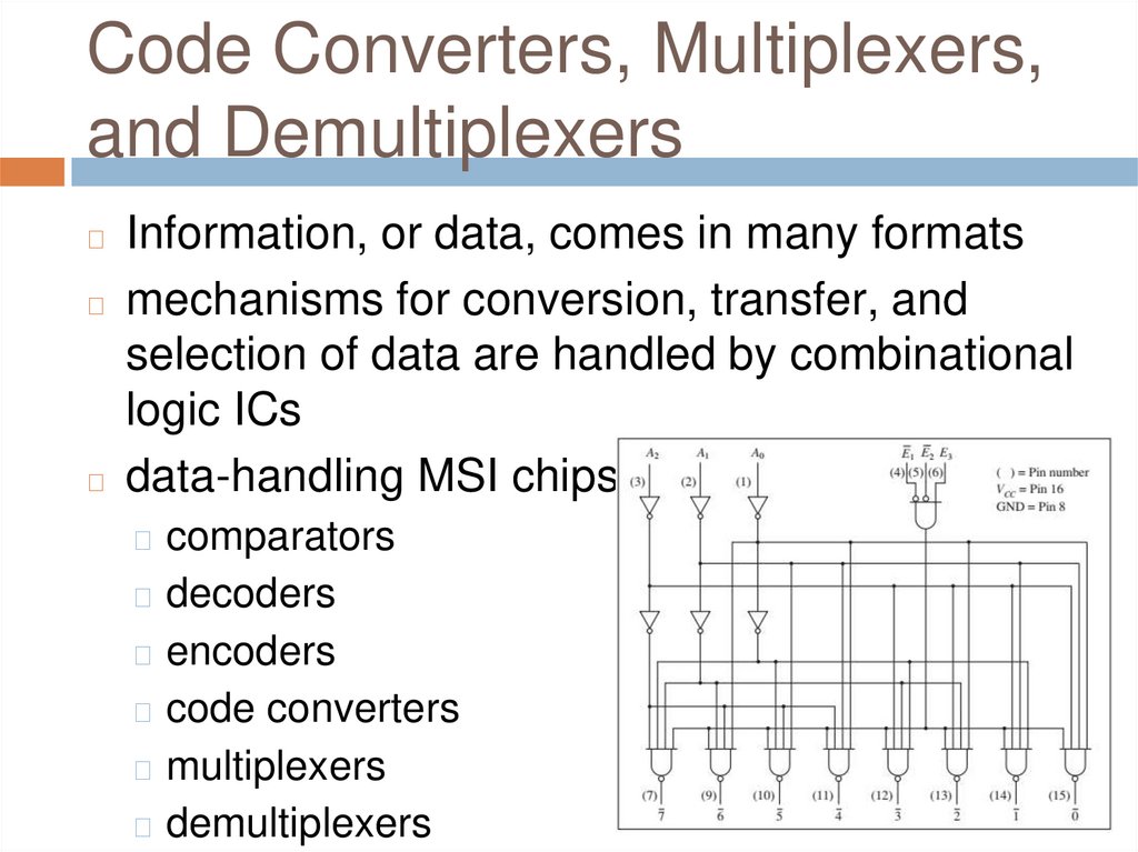
Information, or data, comes in many formats
◻ mechanisms for conversion, transfer, and
selection of data are handled by combinational
logic ICs
◻ data-handling MSI chips
◻
◻ comparators
◻ decoders
◻ encoders
◻ code converters
◻ multiplexers
◻ demultiplexers
4.
Comparators◻
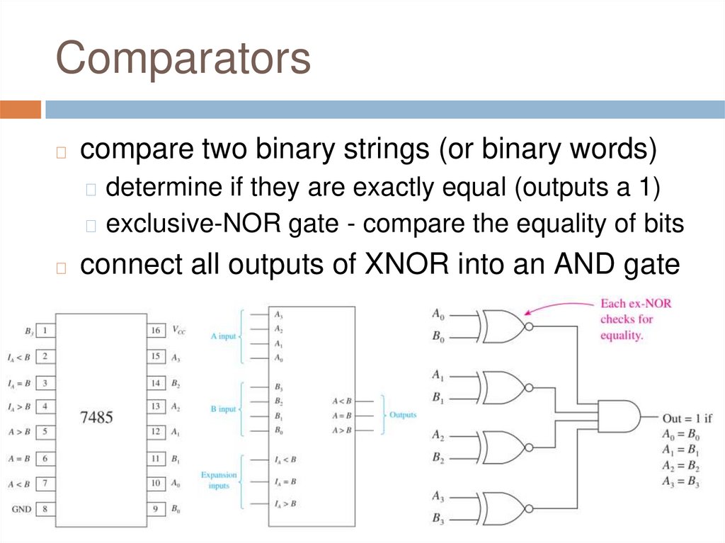
compare two binary strings (or binary words)
◻ determine if they are exactly equal (outputs a 1)
◻ exclusive-NOR gate - compare the equality of bits
◻
connect all outputs of XNOR into an AND gate
5.
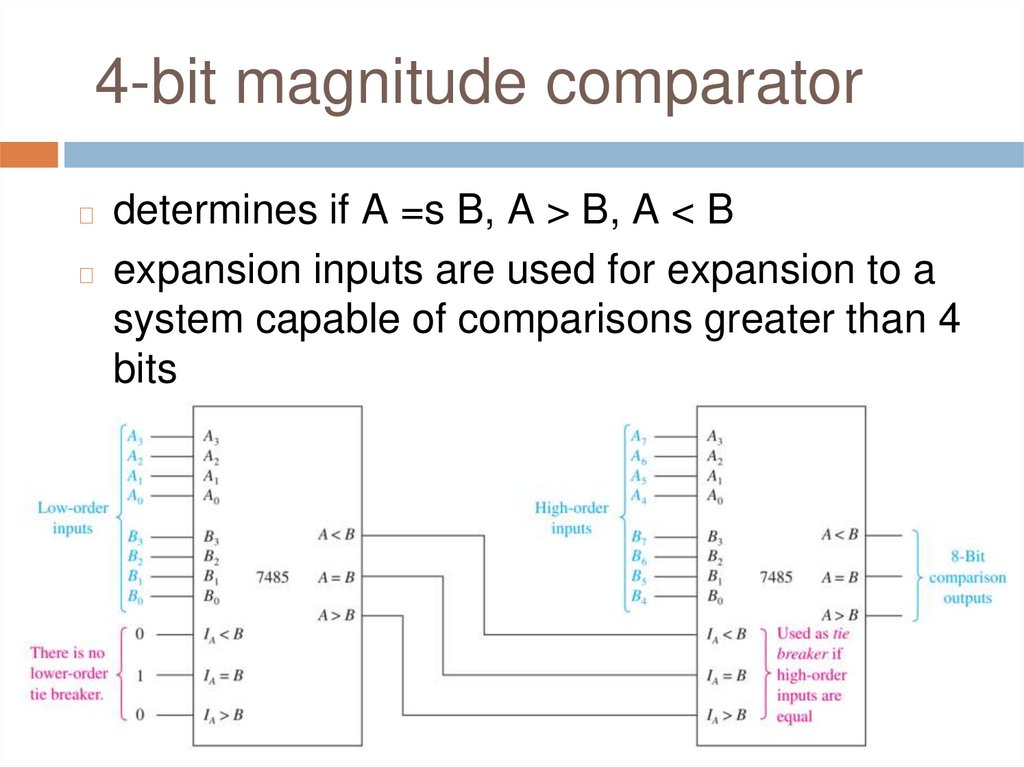
4-bit magnitude comparatordetermines if A =s B, A > B, A < B
◻ expansion inputs are used for expansion to a
system capable of comparisons greater than 4
bits
◻
6.
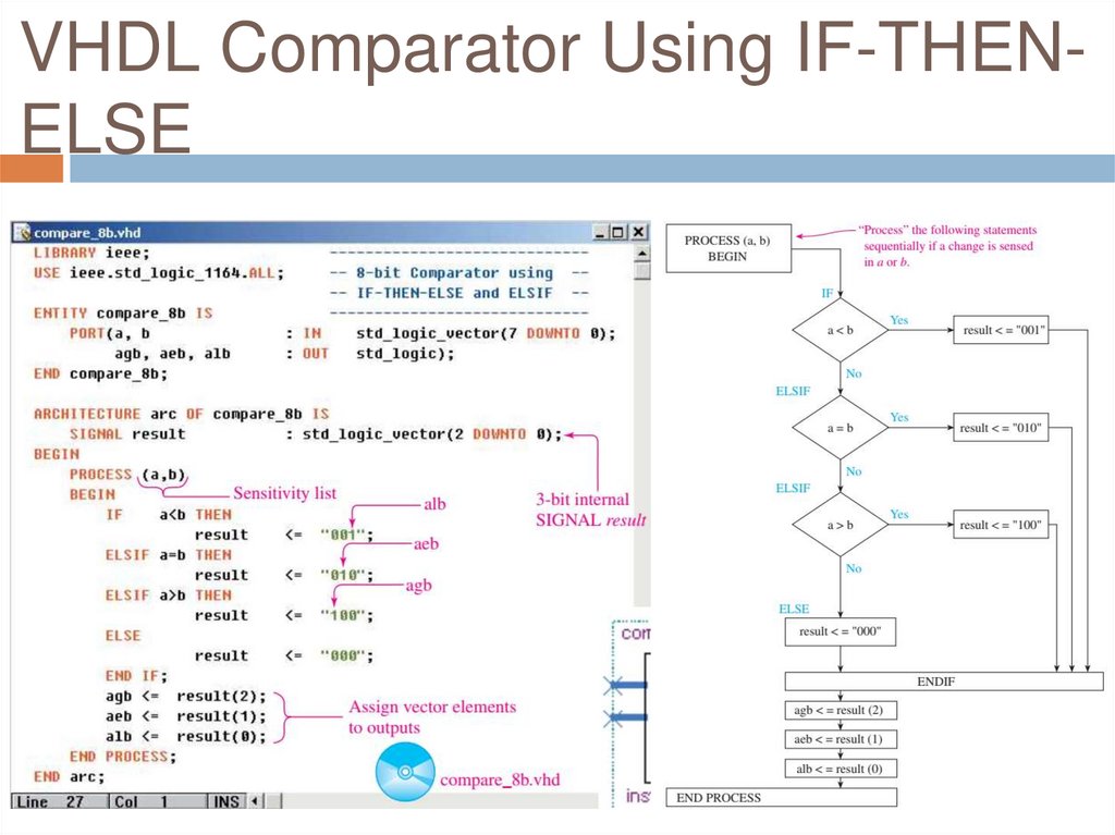
VHDL Comparator Using IF-THENELSE7.
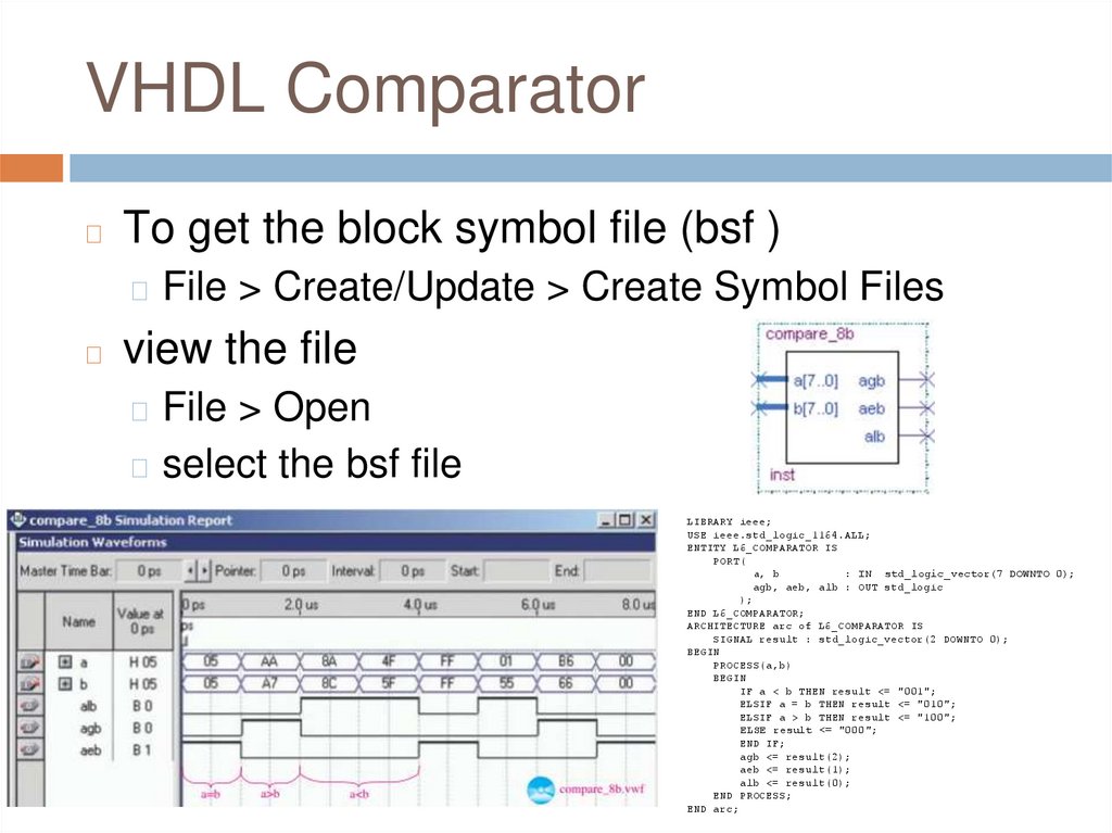
VHDL Comparator◻
To get the block symbol file (bsf )
◻ File > Create/Update > Create Symbol Files
◻
view the file
◻ File > Open
◻ select the bsf file
LIBRARY ieee;
USE ieee.std_logic_1164.ALL;
ENTITY L6_COMPARATOR IS
PORT(
a, b
: IN std_logic_vector(7 DOWNTO 0);
agb, aeb, alb : OUT std_logic
);
END L6_COMPARATOR;
ARCHITECTURE arc of L6_COMPARATOR IS
SIGNAL result : std_logic_vector(2 DOWNTO 0);
BEGIN
PROCESS(a,b)
BEGIN
IF a < b THEN result <= "001";
ELSIF a = b THEN result <= "010";
ELSIF a > b THEN result <= "100";
ELSE result <= "000";
END IF;
agb <= result(2);
aeb <= result(1);
alb <= result(0);
END PROCESS;
END arc;
8.
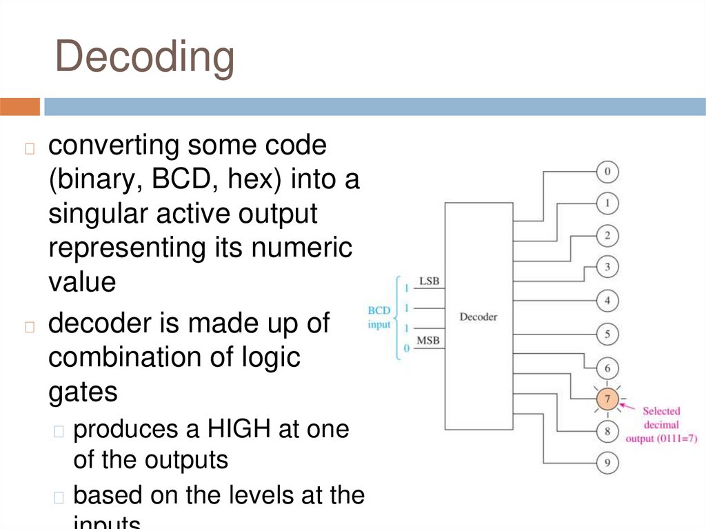
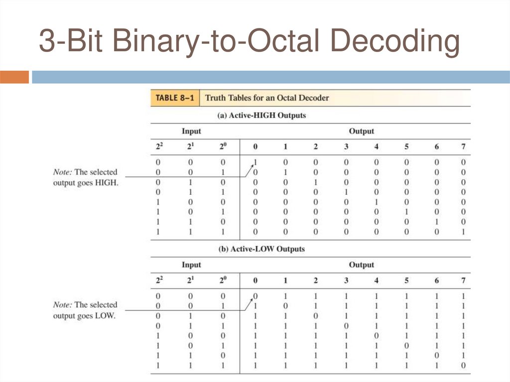
Decodingconverting some code
(binary, BCD, hex) into a
singular active output
representing its numeric
value
◻ decoder is made up of
combination of logic
gates
◻
◻ produces a HIGH at one
of the outputs
◻ based on the levels at the
9.
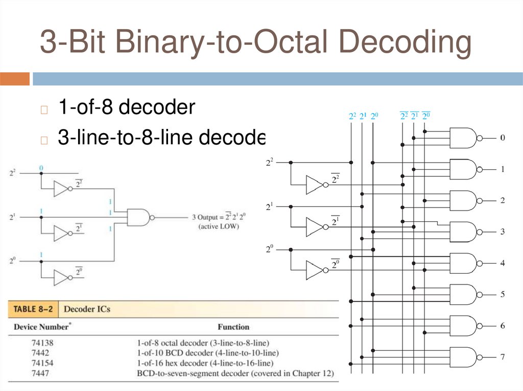
3-Bit Binary-to-Octal Decoding10.
3-Bit Binary-to-Octal Decoding1-of-8 decoder
◻ 3-line-to-8-line decoder
◻
11.
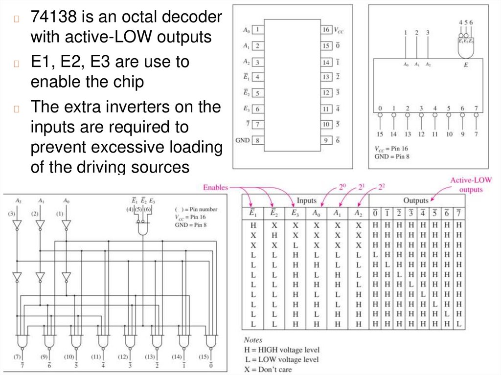
74138 is an octal decoderwith active-LOW outputs
◻ E1, E2, E3 are use to
enable the chip
◻ The extra inverters on the
inputs are required to
prevent excessive loading
of the driving sources
◻
12.
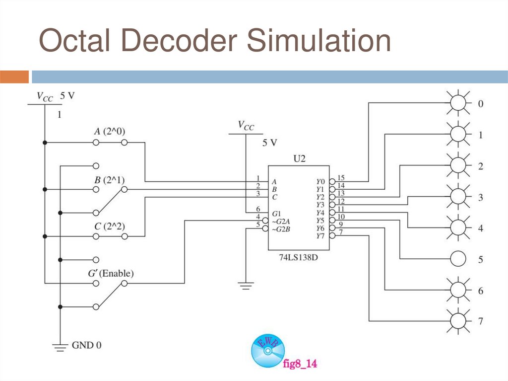
Octal Decoder Simulation13.
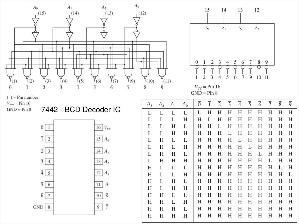
7442 - BCD Decoder IC14.
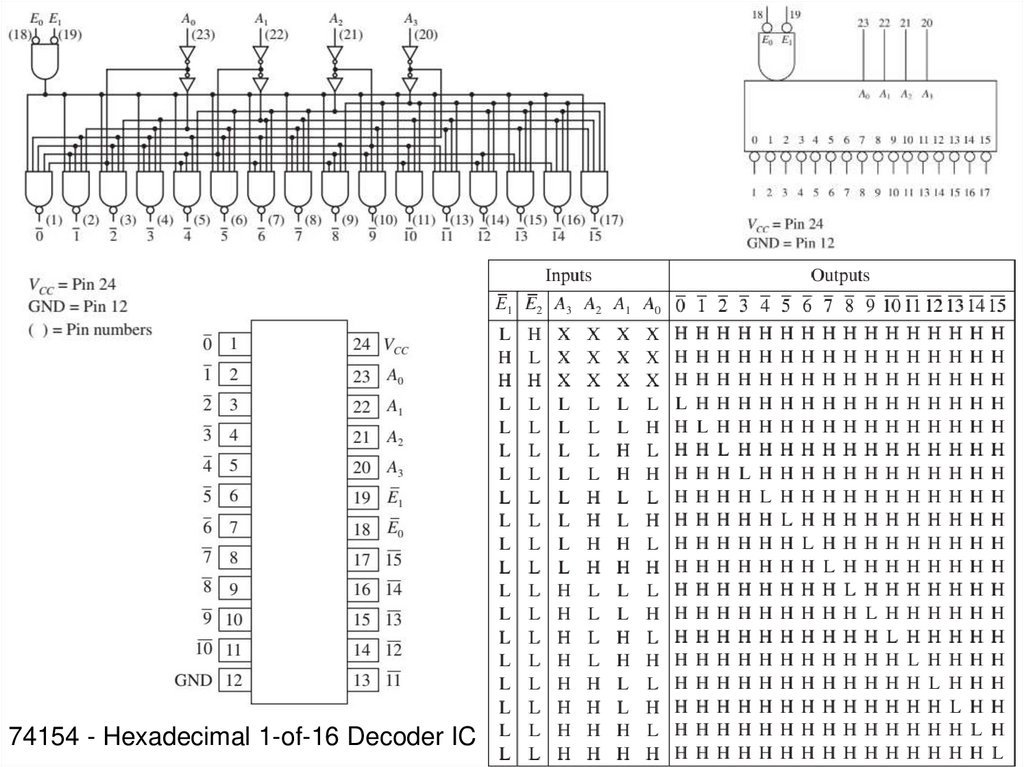
74154 - Hexadecimal 1-of-16 Decoder IC15.
Review Questions1.
2.
3.
4.
More than one output of the 7485 comparator
can be simultaneously HIGH. True or false?
A BCD-to-decimal decoder has how many
inputs and how many outputs?
An octal decoder with active-LOW outputs
will output seven LOWs and one HIGH for
each combination of inputs. True or false?
Only one of the three enable inputs must be
satisfied to enable the 74138 decoder IC.
True or false?
16.
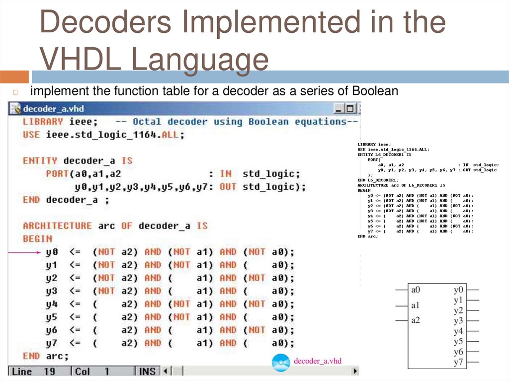
Decoders Implemented in theVHDL Language
◻
implement the function table for a decoder as a series of Boolean
equations
LIBRARY ieee;
USE ieee.std_logic_1164.ALL;
ENTITY L6_DECODER1 IS
PORT(
a0, a1, a2
: IN std_logic;
y0, y1, y2, y3, y4, y5, y6, y7 : OUT std_logic
);
END L6_DECODER1;
ARCHITECTURE arc OF L6_DECODER1 IS
BEGIN
y0 <= (NOT a2) AND (NOT a1) AND (NOT a0);
y1 <= (NOT a2) AND (NOT a1) AND (
a0);
y2 <= (NOT a2) AND (
a1) AND (NOT a0);
y3 <= (NOT a2) AND (
a1) AND (
a0);
y4 <= (
a2) AND (NOT a1) AND (NOT a0);
y5 <= (
a2) AND (NOT a1) AND (
a0);
y6 <= (
a2) AND (
a1) AND (NOT a0);
y7 <= (
a2) AND (
a1) AND (
a0);
END arc;
17.
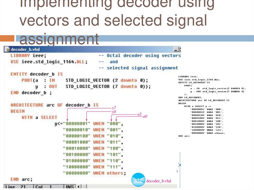
Implementing decoder usingvectors and selected signal
assignment
LIBRARY ieee;
USE ieee.std_logic_1164.ALL;
ENTITY L6_DECODER2 IS
PORT(
a : IN std_logic_vector(2 DOWNTO 0);
y : OUT std_logic_vector(7 DOWNTO 0)
);
END L6_DECODER2;
ARCHITECTURE arc OF L6_DECODER2 IS
BEGIN
WITH a SELECT y <=
"00000001" WHEN "000",
"00000010" WHEN "001",
"00000100" WHEN "010",
"00001000" WHEN "011",
"00010000" WHEN "100",
"00100000" WHEN "101",
"01000000" WHEN "110",
"10000000" WHEN "111",
"00000000" WHEN others;
END arc;
18.
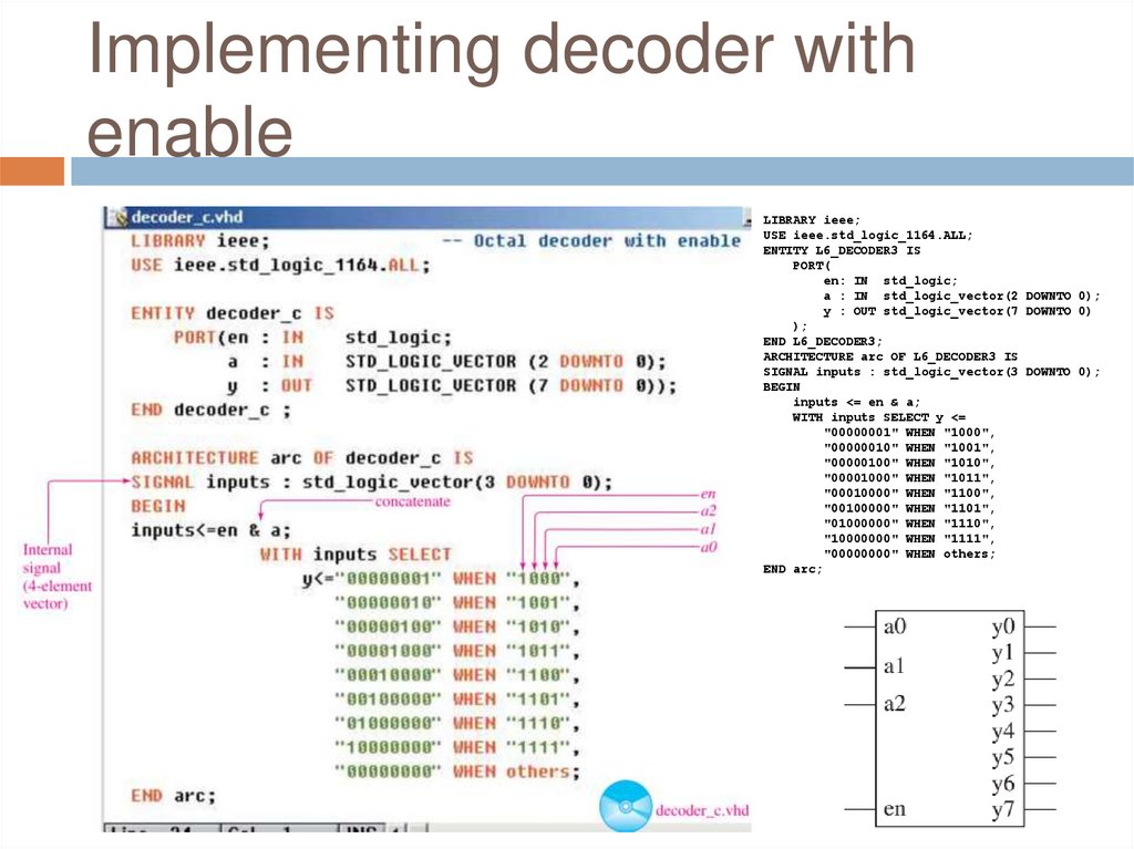
Implementing decoder withenable
LIBRARY ieee;
USE ieee.std_logic_1164.ALL;
ENTITY L6_DECODER3 IS
PORT(
en: IN std_logic;
a : IN std_logic_vector(2 DOWNTO 0);
y : OUT std_logic_vector(7 DOWNTO 0)
);
END L6_DECODER3;
ARCHITECTURE arc OF L6_DECODER3 IS
SIGNAL inputs : std_logic_vector(3 DOWNTO 0);
BEGIN
inputs <= en & a;
WITH inputs SELECT y <=
"00000001" WHEN "1000",
"00000010" WHEN "1001",
"00000100" WHEN "1010",
"00001000" WHEN "1011",
"00010000" WHEN "1100",
"00100000" WHEN "1101",
"01000000" WHEN "1110",
"10000000" WHEN "1111",
"00000000" WHEN others;
END arc;
19.
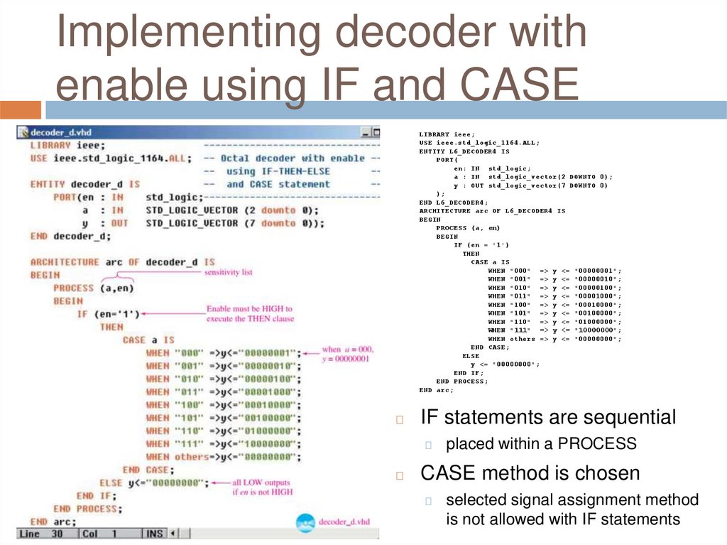
Implementing decoder withenable using IF and CASE
LIBRARY ieee;
USE ieee.std_logic_1164.ALL;
ENTITY L6_DECODER4 IS
PORT(
en: IN std_logic;
a : IN std_logic_vector(2 DOWNTO 0);
y : OUT std_logic_vector(7 DOWNTO 0)
);
END L6_DECODER4;
ARCHITECTURE arc OF L6_DECODER4 IS
BEGIN
PROCESS (a, en)
BEGIN
IF (en = '1')
THEN
CASE a IS
WHEN "000" => y <= "00000001";
WHEN "001" => y <= "00000010";
WHEN "010" => y <= "00000100";
WHEN "011" => y <= "00001000";
WHEN "100" => y <= "00010000";
WHEN "101" => y <= "00100000";
WHEN "110" => y <= "01000000";
WHEN "111" => y <= "10000000";
WHEN others => y <= "00000000";
END CASE;
ELSE
y <= "00000000";
END IF;
END PROCESS;
END arc;
◻
IF statements are sequential
◻
◻
placed within a PROCESS
CASE method is chosen
◻
selected signal assignment method
is not allowed with IF statements
20.
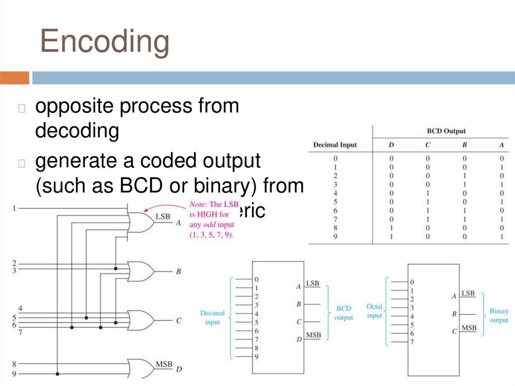
Encodingopposite process from
decoding
◻ generate a coded output
(such as BCD or binary) from
a singular active numeric
input line
◻
21.
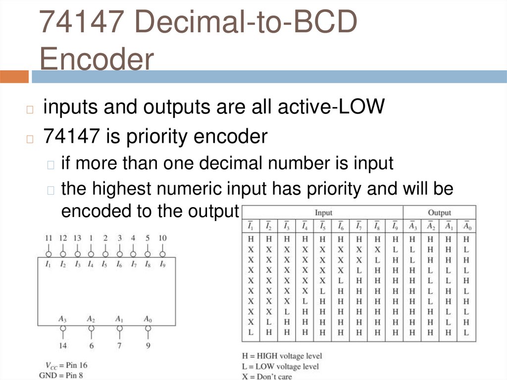
74147 Decimal-to-BCDEncoder
inputs and outputs are all active-LOW
◻ 74147 is priority encoder
◻
◻ if more than one decimal number is input
◻ the highest numeric input has priority and will be
encoded to the output
22.
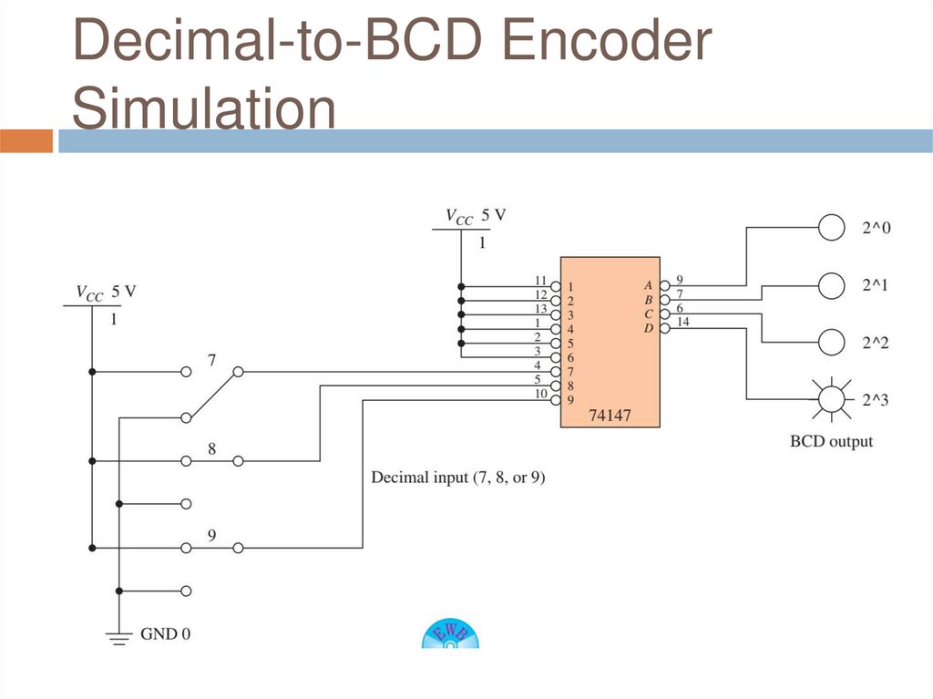
Decimal-to-BCD EncoderSimulation
23.
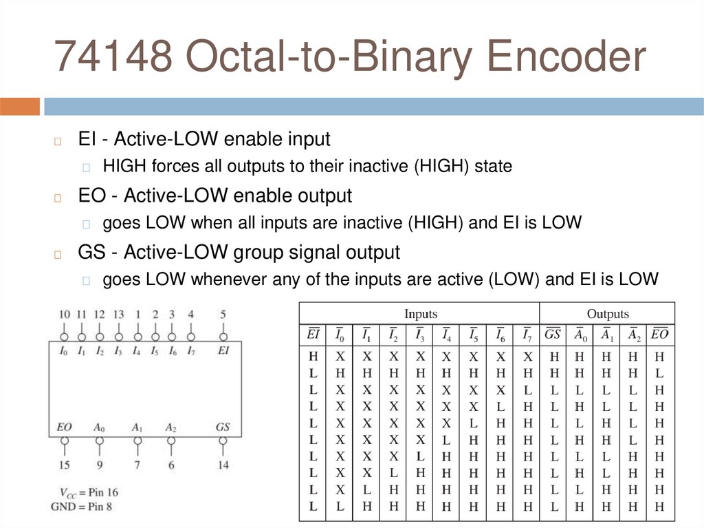
74148 Octal-to-Binary Encoder◻
EI - Active-LOW enable input
◻
◻
EO - Active-LOW enable output
◻
◻
HIGH forces all outputs to their inactive (HIGH) state
goes LOW when all inputs are inactive (HIGH) and EI is LOW
GS - Active-LOW group signal output
◻
goes LOW whenever any of the inputs are active (LOW) and EI is LOW
24.
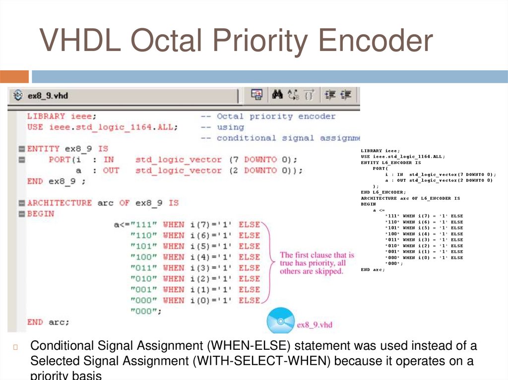
VHDL Octal Priority EncoderLIBRARY ieee;
USE ieee.std_logic_1164.ALL;
ENTITY L6_ENCODER IS
PORT(
i : IN std_logic_vector(7 DOWNTO 0);
a : OUT std_logic_vector(2 DOWNTO 0)
);
END L6_ENCODER;
ARCHITECTURE arc OF L6_ENCODER IS
BEGIN
a <=
"111" WHEN i(7) = '1' ELSE
"110" WHEN i(6) = '1' ELSE
"101" WHEN i(5) = '1' ELSE
"100" WHEN i(4) = '1' ELSE
"011" WHEN i(3) = '1' ELSE
"010" WHEN i(2) = '1' ELSE
"001" WHEN i(1) = '1' ELSE
"000" WHEN i(0) = '1' ELSE
"000";
END arc;
◻
Conditional Signal Assignment (WHEN-ELSE) statement was used instead of a
Selected Signal Assignment (WITH-SELECT-WHEN) because it operates on a
priority basis
25.
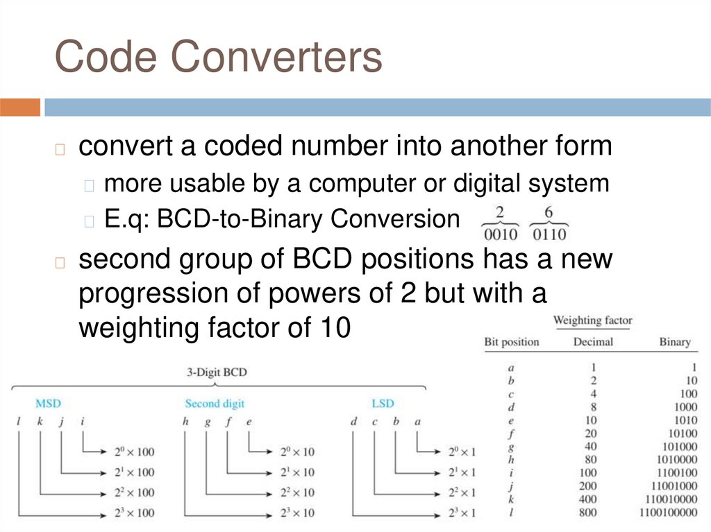
Code Converters◻
convert a coded number into another form
◻ more usable by a computer or digital system
◻ E.q: BCD-to-Binary Conversion
◻
second group of BCD positions has a new
progression of powers of 2 but with a
weighting factor of 10
26.
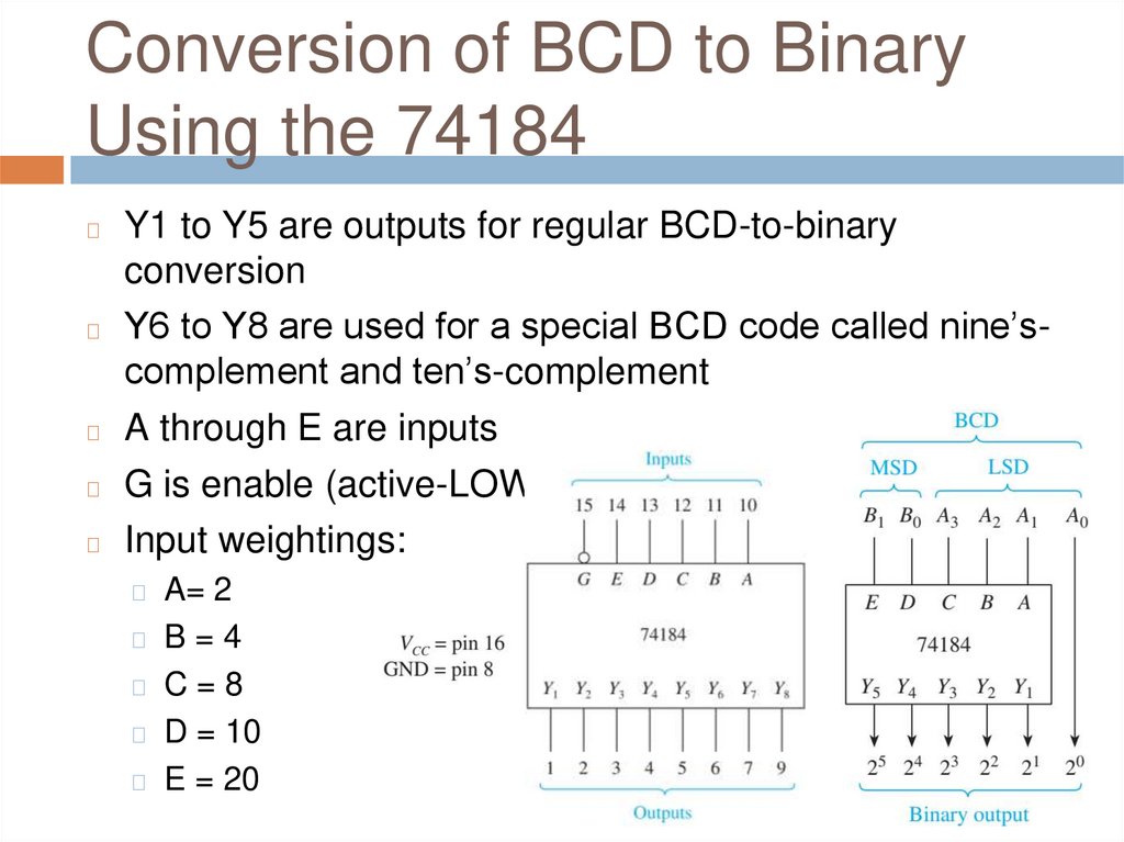
Conversion of BCD to BinaryUsing the 74184
Y1 to Y5 are outputs for regular BCD-to-binary
conversion
◻ Y6 to Y8 are used for a special BCD code called nine’scomplement and ten’s-complement
◻ A through E are inputs
◻ G is enable (active-LOW)
◻ Input weightings:
◻
◻ A= 2
◻ B=4
◻ C=8
◻ D = 10
◻ E = 20
27.
28.
Gray Code◻
used primarily for indicating
the angular position of a
shaft on rotating machinery
29.
Review Questions1.
2.
3.
4.
How does an encoder differ from a decoder?
If more than one input to a priority encoder is
active, which input will be encoded?
What are the input weighting factors for A, B,
C, D, E inputs of 74184 IC?
What is the difference between Binary and
Gray code?
30.
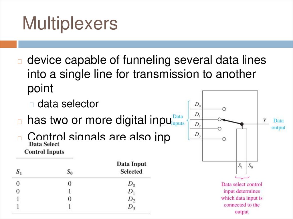
Multiplexers◻
device capable of funneling several data lines
into a single line for transmission to another
point
◻ data selector
has two or more digital inputs
◻ Control signals are also input
◻
31.
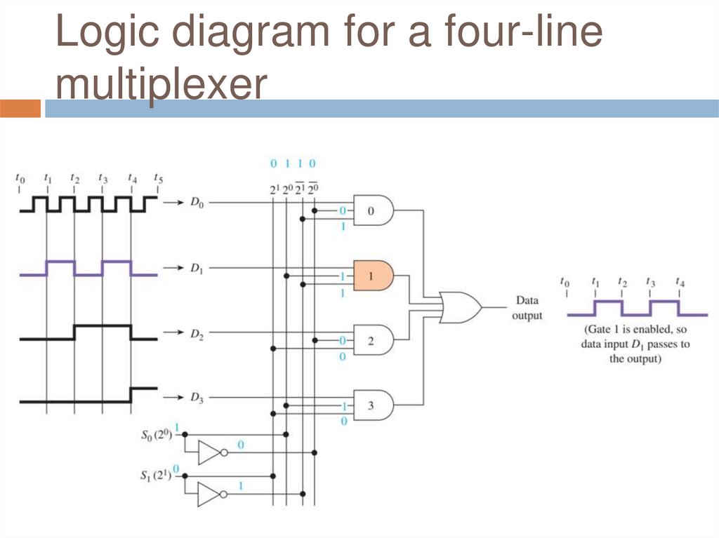
Logic diagram for a four-linemultiplexer
32.
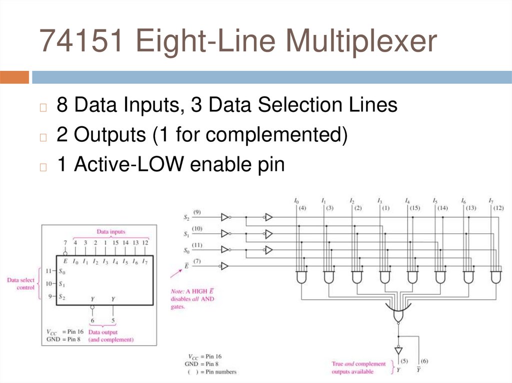
74151 Eight-Line Multiplexer8 Data Inputs, 3 Data Selection Lines
◻ 2 Outputs (1 for complemented)
◻ 1 Active-LOW enable pin
◻
33.
34.
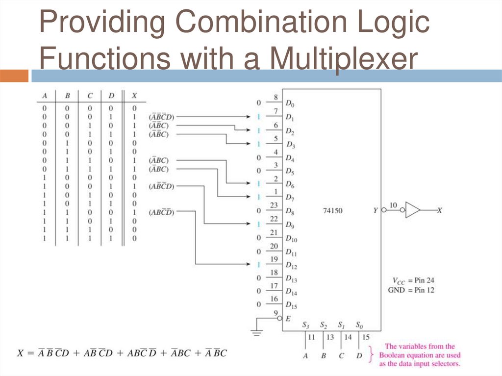
Providing Combination LogicFunctions with a Multiplexer
35.
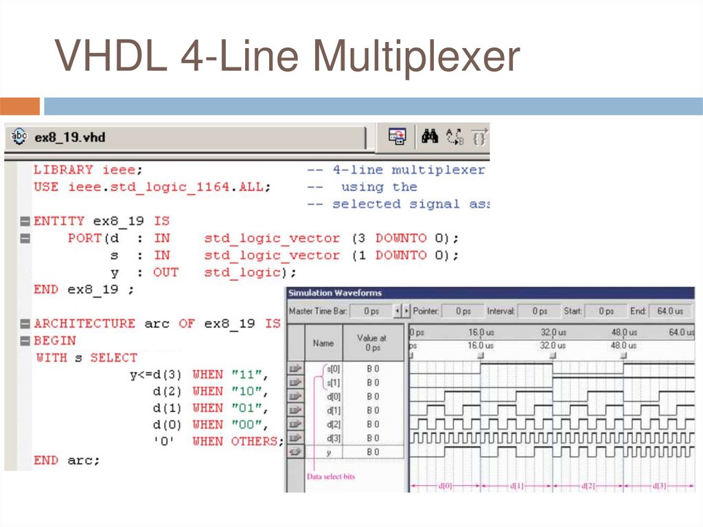
VHDL 4-Line Multiplexer36.
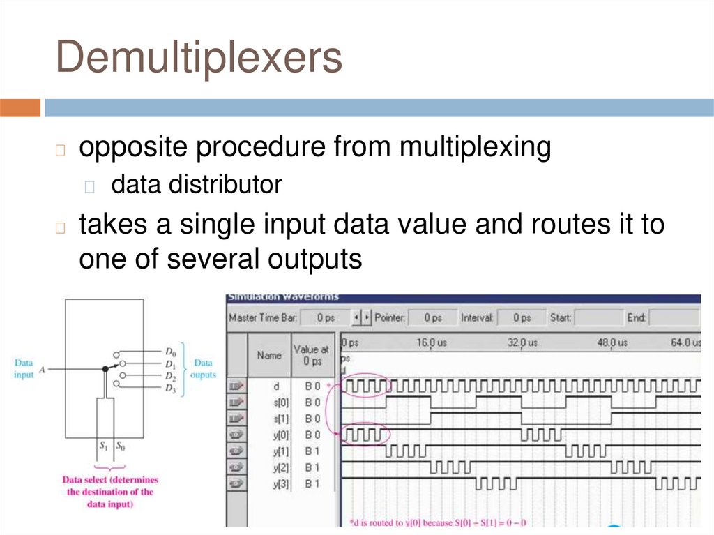
Demultiplexers◻
opposite procedure from multiplexing
◻
◻
data distributor
takes a single input data value and routes it to
one of several outputs
37.
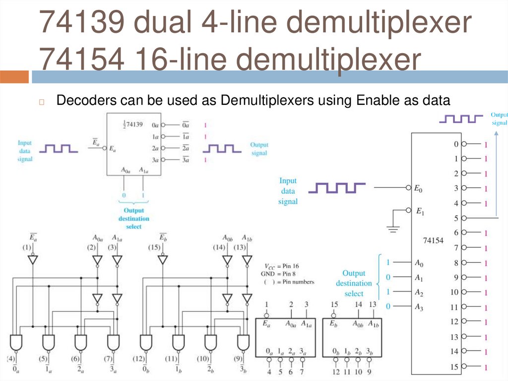
74139 dual 4-line demultiplexer74154 16-line demultiplexer
◻
Decoders can be used as Demultiplexers using Enable as data
input
38.
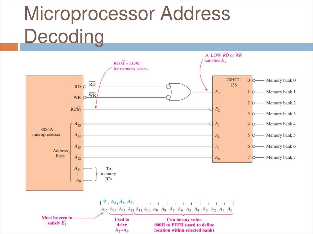
Microprocessor AddressDecoding
39.
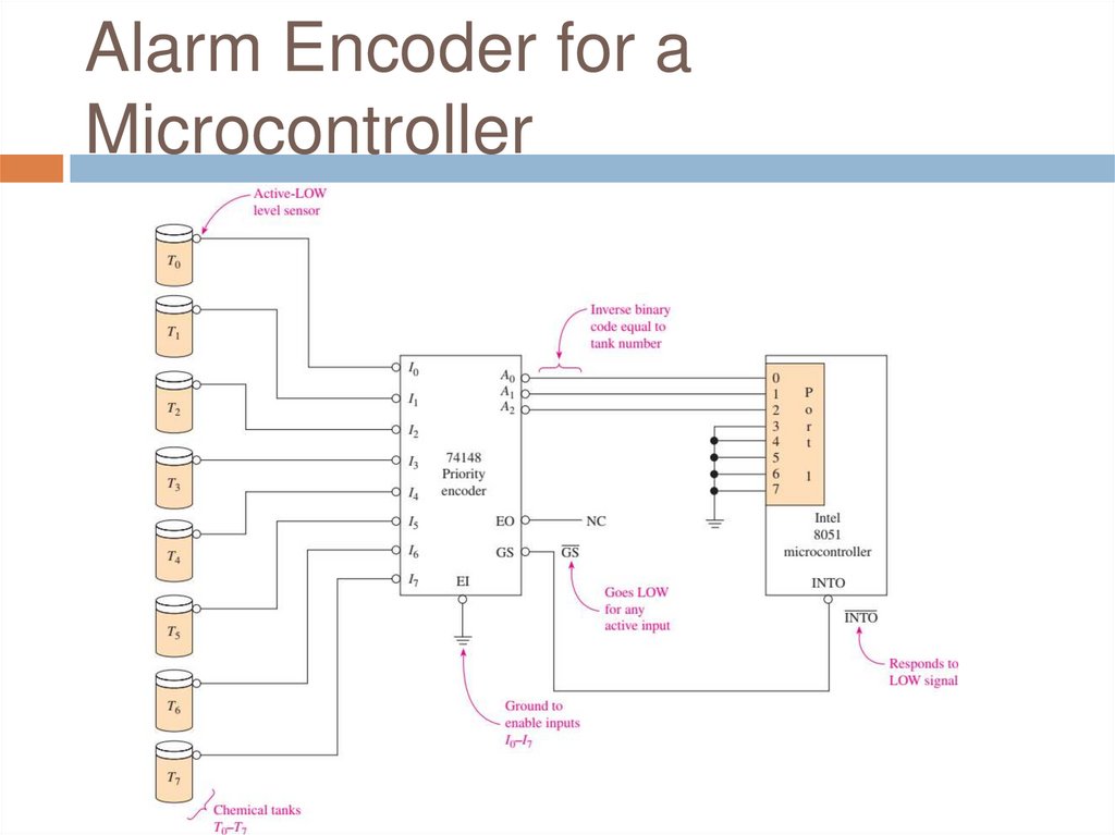
Alarm Encoder for aMicrocontroller
40.
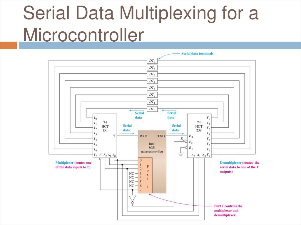
Serial Data Multiplexing for aMicrocontroller
41.
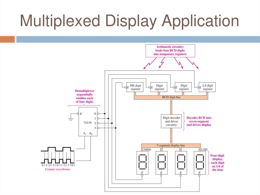
Multiplexed Display Application42.
Review Questions1.
2.
3.
A multiplexer sometimes called a data
______ (selector/distributor) whereas
demutiplexer is sometimes called data ____
(selector/distributor)?
What is the function of the S0, S1, and S2
pins on the 74151 multiplexer?
What is the function of the A0, A1, A2, and
A3 pins on the 74154 demultiplexer?
43.
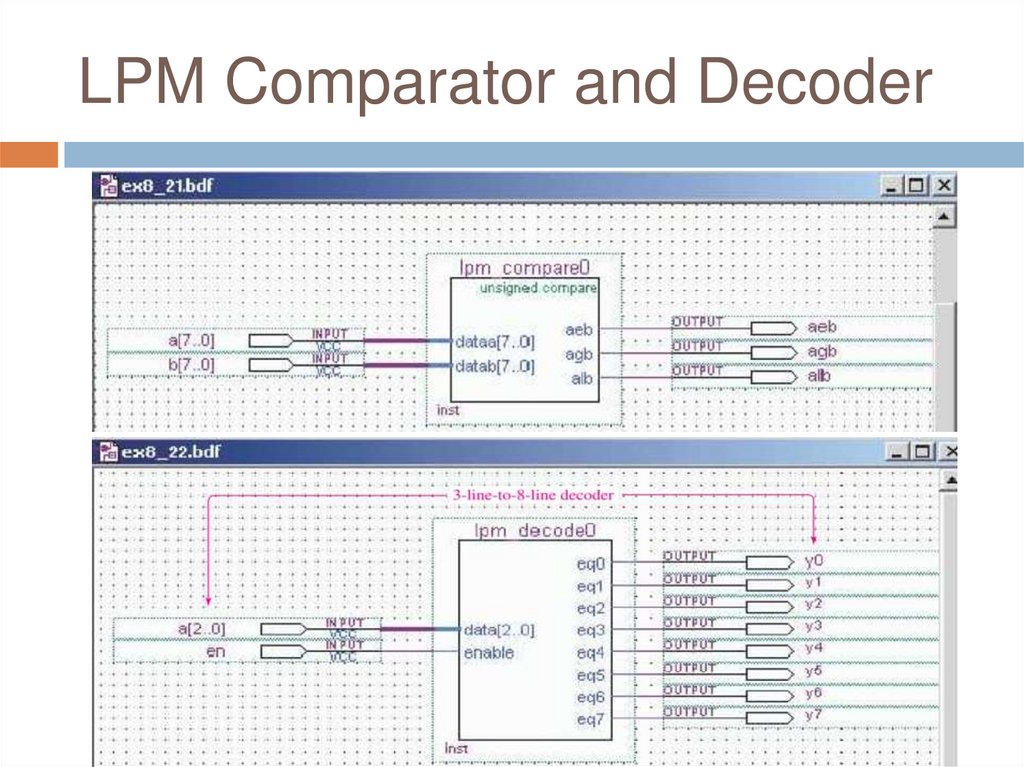
LPM Comparator and Decoder44.
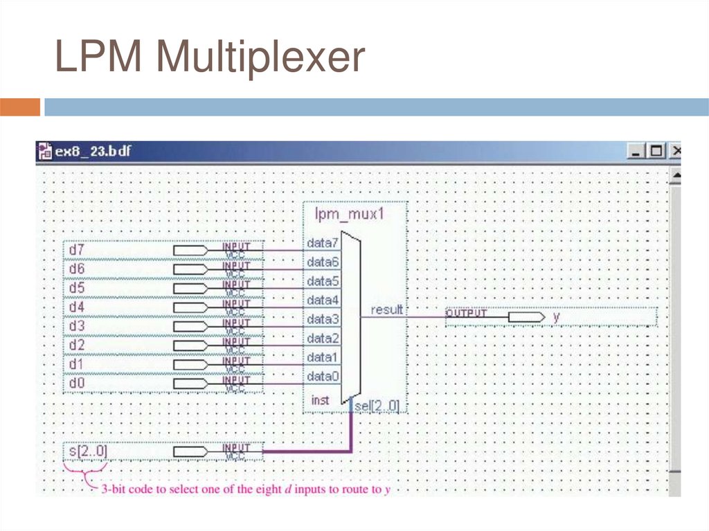
LPM Multiplexer45.
Q&AAny Questions?