


 Программное обеспечение
Похожие презентации:

")


Minimum Equipment List (MEL)
1.
Minimum Equipment List(MEL)
Document Reference: FAS / DHC-8-402 / MEL / 01
Revision 2, Dated 29-Mar-2015
2.
3.
For this training the referenced MEL is for the Q400 (DHC-8-402).The format of all MEL’s is similar and falls under the following
regulation:
CAR Part IV, Operational Regulations – CAR MEL
Access to the MEL’s for all aircraft operated by Falcon Aviation is gained
through Q-Pulse (refer previous slide).
4.
ObjectiveAt the completion of this training you will be able to:
•Navigate your way through the Minimum Equipment List
•Determine if continued airworthiness is available when a
defect comes to your attention
•Defer the MEL item from the Techlog to the deferred defect
log.
5.
Topics to be discussedPart 1: MEL Origin & Philosophy.
Part 2: MEL Structure
Part 3: Process & Techlog Entry
Part 4: Defect Repair
Part 4: MEL Multimedia
6.
MEL Origin & PhilosophyPart 1
7.
MEL Origin & Philosophy• Master Minimum Equipment List
- A Master Minimum Equipment List (MMEL) is an approved document
created specifically to regulate the dispatch of an aircraft type with
inoperative equipment.
- It establishes the aircraft equipment allowed to be inoperative under
certain conditions for a specific type of aircraft and still provides an
acceptable level of safety.
- The MMEL contains the conditions, limitations and procedures required
for operating the aircraft with these items inoperative.
- The MMEL forms the basis for development and review of an individual
operator’s Minimum Equipment List (MEL).
8.
End of Part 19.
Minimum Equipment List(MEL)
MEL Structure
Part 2
10.
MEL Structure• All modern Airworthiness Authorities require that a MEL be
carried in the aircraft when flown
• Therefore the MEL is a National Aviation Approved document.
• If the MEL meets their requirements it will be endorsed
11.
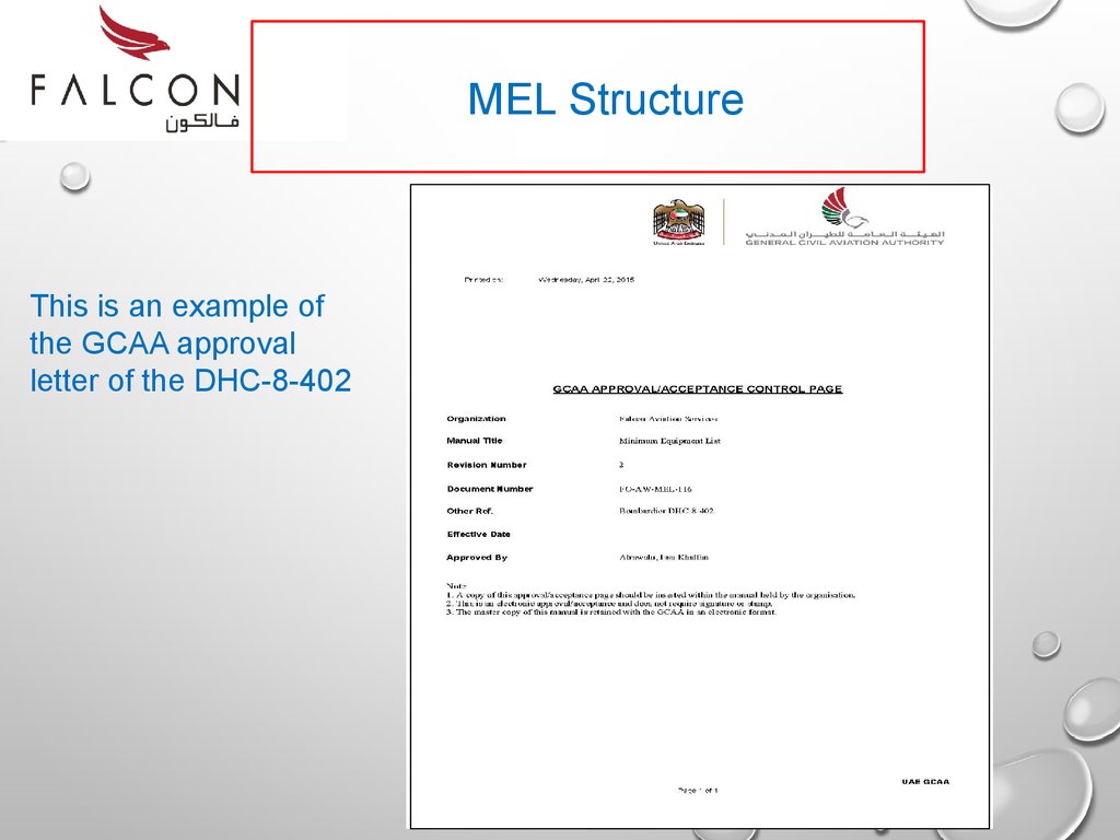
MEL StructureThis is an example of
the GCAA approval
letter of the DHC-8-402
12.
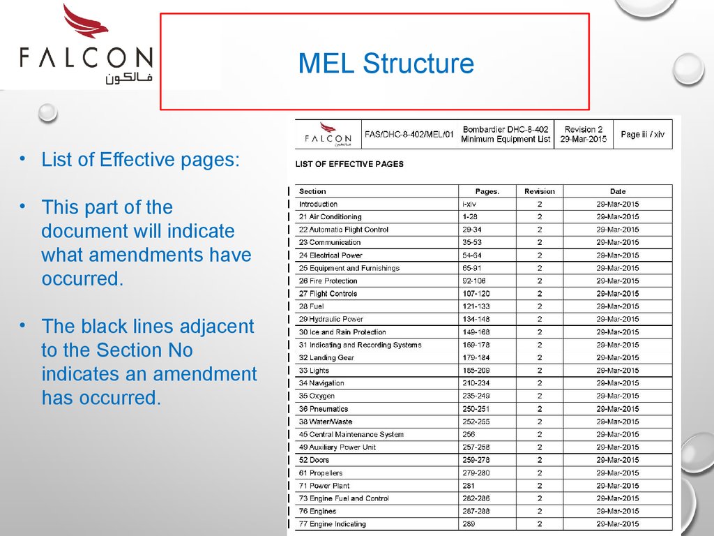
MEL Structure• List of Effective pages:
• This part of the
document will indicate
what amendments have
occurred.
• The black lines adjacent
to the Section No
indicates an amendment
has occurred.
13.
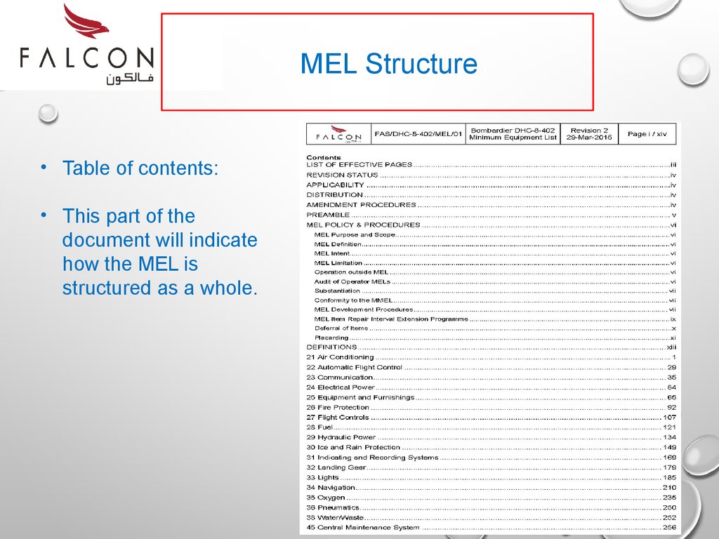
MEL Structure• Table of contents:
• This part of the
document will indicate
how the MEL is
structured as a whole.
14.
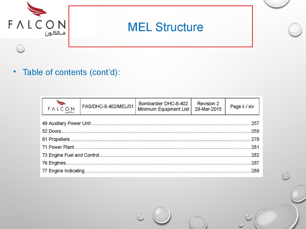
MEL Structure• Table of contents (cont’d):
15.
MEL Structure• Preamble:
- is an introductory statement for the correct usage and application of
the part 1 of the MEL manual.
- Refer to the MEL supplied and review the content of the preamble.
- The structure and content of the preamble is usually in a
standardized format.
16.
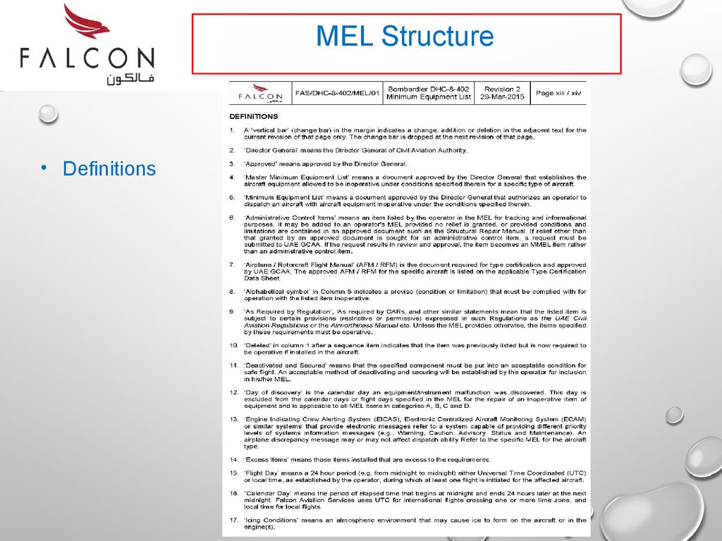
MEL Structure• Definitions:
- Also listed in the preamble will be a list of common definitions used
throughout the MEL document.
- You should make yourself familiar with these definitions. Please
take time now to read the definitions in the MEL supplied.
17.
MEL Structure• Definitions
18.
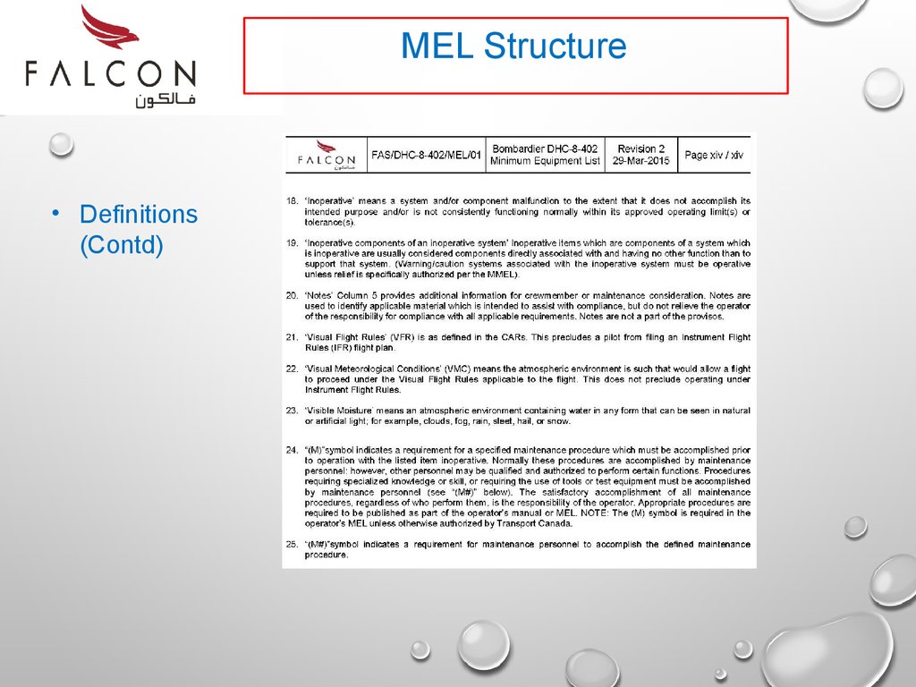
MEL Structure• Definitions
(Contd)
19.
RememberAll aircraft have their MEL’s designed around a standardized format but
the content can be very different. Always refer to the MEL that is
applicable to the aircraft type & registration.
20.
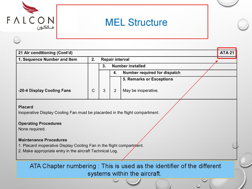
MEL StructureATA Chapter numbering : This is used as the identifier of the different
systems within the aircraft.
21.
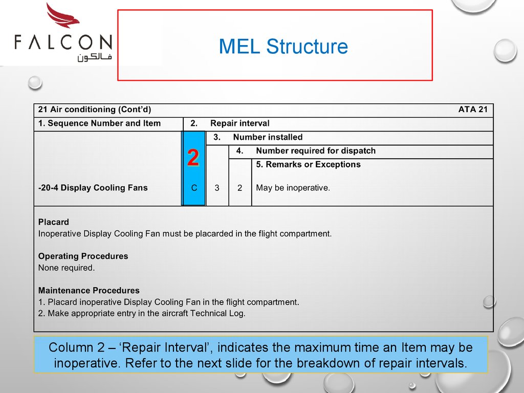
MEL StructureThis is a standard MEL format – 5 columns
22.
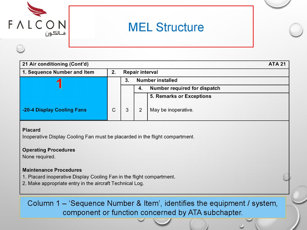
MEL StructureColumn 1 – ‘Sequence Number & Item’, identifies the equipment / system,
component or function concerned by ATA subchapter.
23.
MEL StructureColumn 2 – ‘Repair Interval’, indicates the maximum time an Item may be
inoperative. Refer to the next slide for the breakdown of repair intervals.
24.
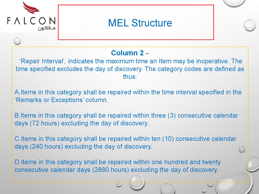
MEL StructureColumn 2 –
‘Repair Interval’, indicates the maximum time an Item may be inoperative. The
time specified excludes the day of discovery. The category codes are defined as
thus:
A.Items in this category shall be repaired within the time interval specified in the
‘Remarks or Exceptions’ column.
B.Items in this category shall be repaired within three (3) consecutive calendar
days (72 hours) excluding the day of discovery.
C.Items in this category shall be repaired within ten (10) consecutive calendar
days (240 hours) excluding the day of discovery.
D.Items in this category shall be repaired within one hundred and twenty
consecutive calendar days (2880 hours) excluding the day of discovery.
25.
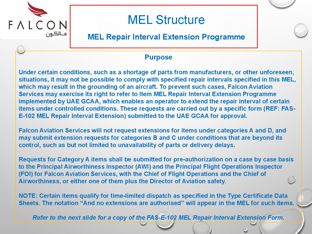
MEL StructureMEL Repair Interval Extension Programme
Purpose
Under certain conditions, such as a shortage of parts from manufacturers, or other unforeseen,
situations, it may not be possible to comply with specified repair intervals specified in this MEL,
which may result in the grounding of an aircraft. To prevent such cases, Falcon Aviation
Services may exercise its right to refer to Item MEL Repair Interval Extension Programme
implemented by UAE GCAA, which enables an operator to extend the repair interval of certain
items under controlled conditions. These requests are carried out by a specific form (REF: FASE-102 MEL Repair Interval Extension) submitted to the UAE GCAA for approval.
Falcon Aviation Services will not request extensions for items under categories A and D, and
may submit extension requests for categories B and C under conditions that are beyond its
control, such as but not limited to unavailability of parts or delivery delays.
Requests for Category A items shall be submitted for pre-authorization on a case by case basis
to the Principal Airworthiness Inspector (AWI) and the Principal Flight Operations Inspector
(FOI) for Falcon Aviation Services, with the Chief of Flight Operations and the Chief of
Airworthiness, or either one of them plus the Director of Aviation safety.
NOTE: Certain items qualify for time-limited dispatch as specified in the Type Certificate Data
Sheets. The notation “And no extensions are authorised” will appear in the MEL for such items.
Refer to the next slide for a copy of the FAS-E-102 MEL Repair Interval Extension Form.
26.
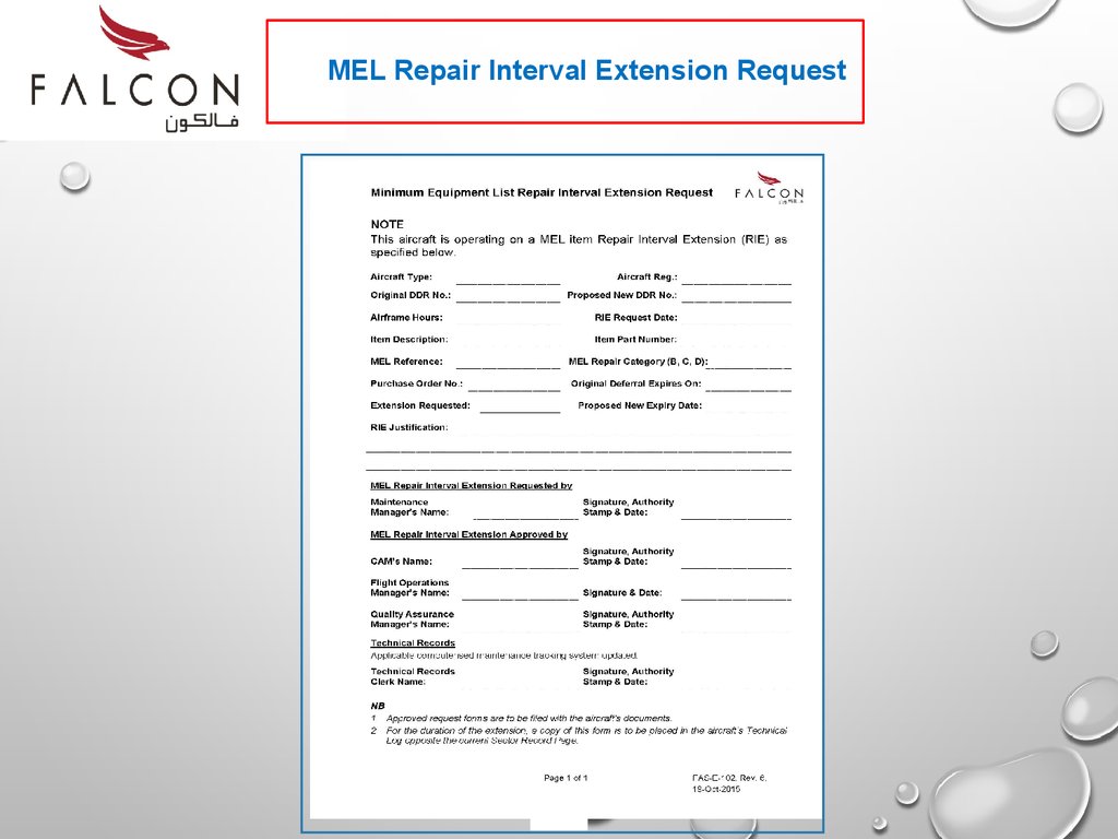
MEL Repair Interval Extension Request26
27.
MEL StructureColumn 3 – ‘Number Installed’, is the number (quantity) of items normally
installed in the aircraft. This number represents the aircraft configuration
considered in developing this MEL
28.
MEL StructureColumn 4 – ‘Number Required for Dispatch’, is the minimum number (quantity)
of items required for operation provided the conditions specified in Column 5 are
met.
29.
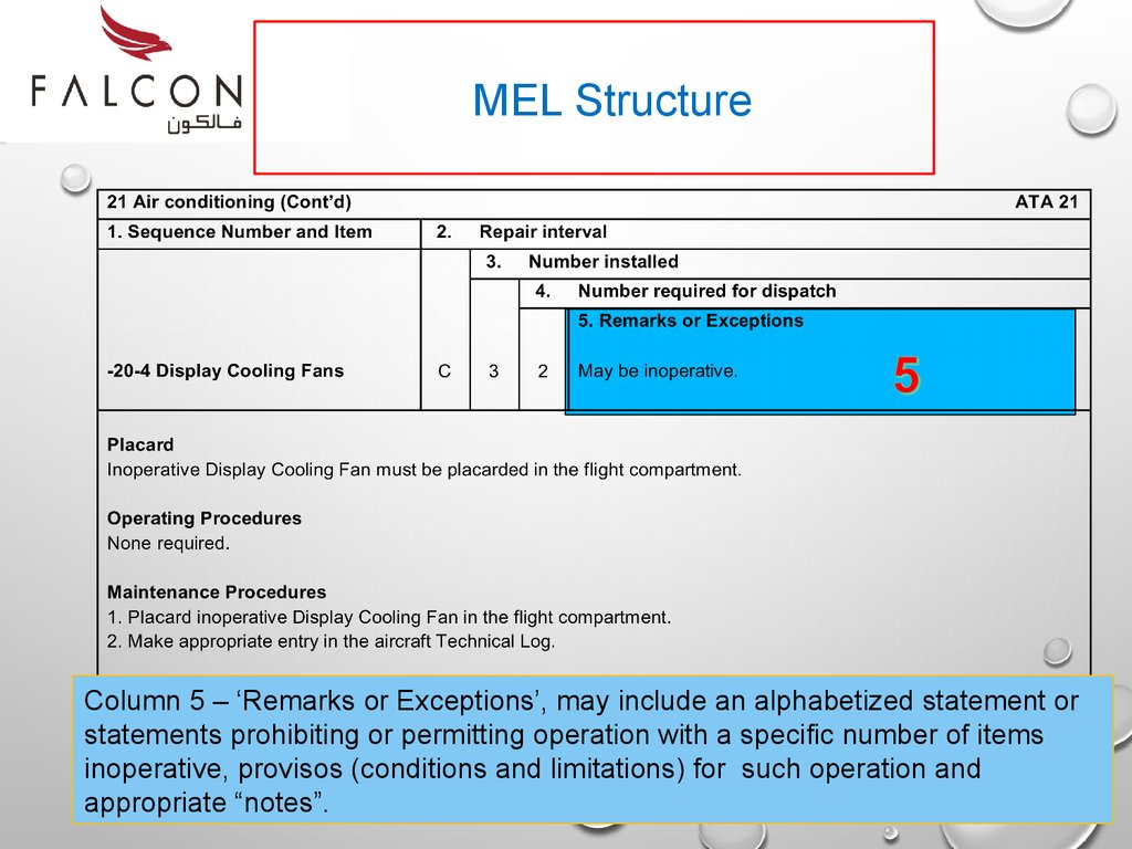
MEL StructureColumn 5 – ‘Remarks or Exceptions’, may include an alphabetized statement or
statements prohibiting or permitting operation with a specific number of items
inoperative, provisos (conditions and limitations) for such operation and
appropriate “notes”.
30.
End of Part 231.
PROCESS &TECH LOG ENTRY
Part 3
AN EXAMPLE OF HOW TO USE THE MEL
32.
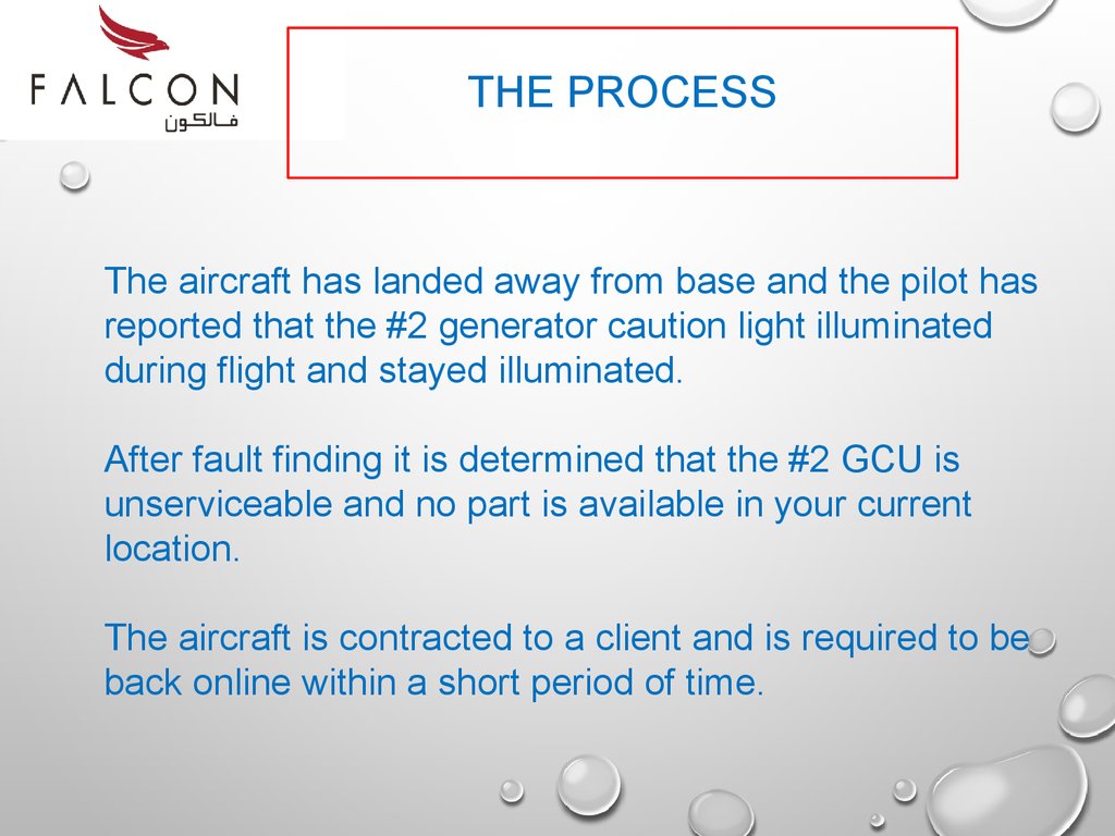
THE PROCESSThe aircraft has landed away from base and the pilot has
reported that the #2 generator caution light illuminated
during flight and stayed illuminated.
After fault finding it is determined that the #2 GCU is
unserviceable and no part is available in your current
location.
The aircraft is contracted to a client and is required to be
back online within a short period of time.
33.
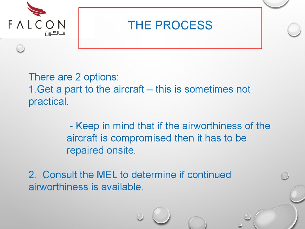
THE PROCESSThere are 2 options:
1.Get a part to the aircraft – this is sometimes not
practical.
- Keep in mind that if the airworthiness of the
aircraft is compromised then it has to be
repaired onsite.
2. Consult the MEL to determine if continued
airworthiness is available.
34.
THE PROCESS1st – we will look at the MEL.
2nd – we will finalise the Techlog entry.
35.
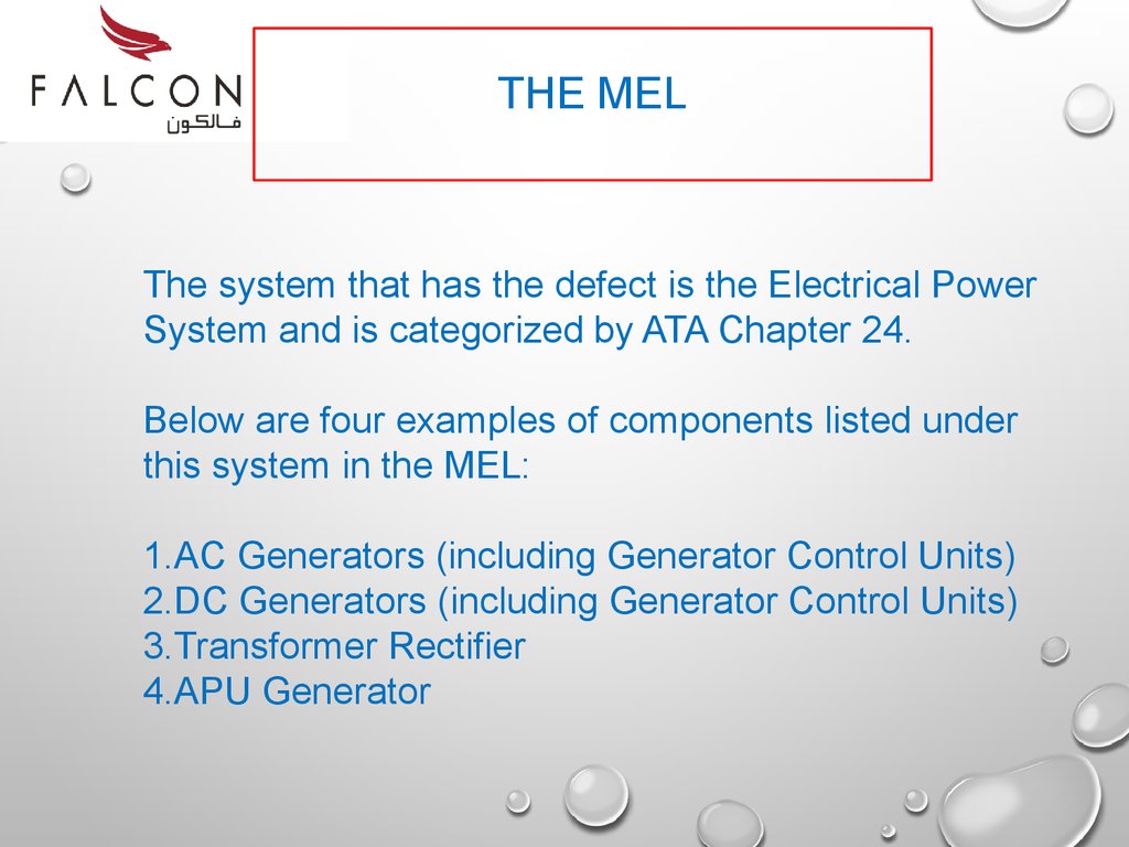
THE MELThe system that has the defect is the Electrical Power
System and is categorized by ATA Chapter 24.
Below are four examples of components listed under
this system in the MEL:
1.AC Generators (including Generator Control Units)
2.DC Generators (including Generator Control Units)
3.Transformer Rectifier
4.APU Generator
36.
24 Electrical Power1. Sequence Number and Item
ATA 24
2.
B
Repair interval
3.
2
-30-2 DC Generator Control Unit –
Start /Termination Function
Number installed
4.
Number required for dispatch
0
5. Remarks or Exceptions
(O) May be inoperative provided the start is manually
terminated at 50% NH.
Placard
Inoperative DC Generator control Unit must be placarded in the flight compartment.
Operating Procedures
1.Carry out associated engine(s) start in sequence in accordance with AFM Section 4 − NORMAL AND
ABNORMAL PROCEDURES, item 4.1.5 − ENGINE START PROCEDURE.
2.Closely monitor associated NH indicator during starting and terminate start function by deselecting ENGINE
START SELECT switch to center SELECT position (off) when NH indication shows positive acceleration beyond
50%.
Maintenance Procedures
1.Placard Engine Start SELECT switch on Engine Start panel on overhead console
2.Make appropriate entry in the aircraft Technical Log.
The Generator is classified in ATA Chapter 24 – Electrical Power
37.
24 Electrical Power1. Sequence Number and Item
ATA 24
2.
B
Repair interval
3.
2
-30-2 DC Generator Control Unit –
Start /Termination Function
Number installed
4.
Number required for dispatch
0
5. Remarks or Exceptions
(O) May be inoperative provided the start is manually
terminated at 50% NH.
Placard
Inoperative DC Generator control Unit must be placarded in the flight compartment.
Operating Procedures
1.Carry out associated engine(s) start in sequence in accordance with AFM Section 4 − NORMAL AND
ABNORMAL PROCEDURES, item 4.1.5 − ENGINE START PROCEDURE.
2.Closely monitor associated NH indicator during starting and terminate start function by deselecting ENGINE
START SELECT switch to center SELECT position (off) when NH indication shows positive acceleration beyond
50%.
Maintenance Procedures
1.Placard Engine Start SELECT switch on Engine Start panel on overhead console
2.Make appropriate entry in the aircraft Technical Log.
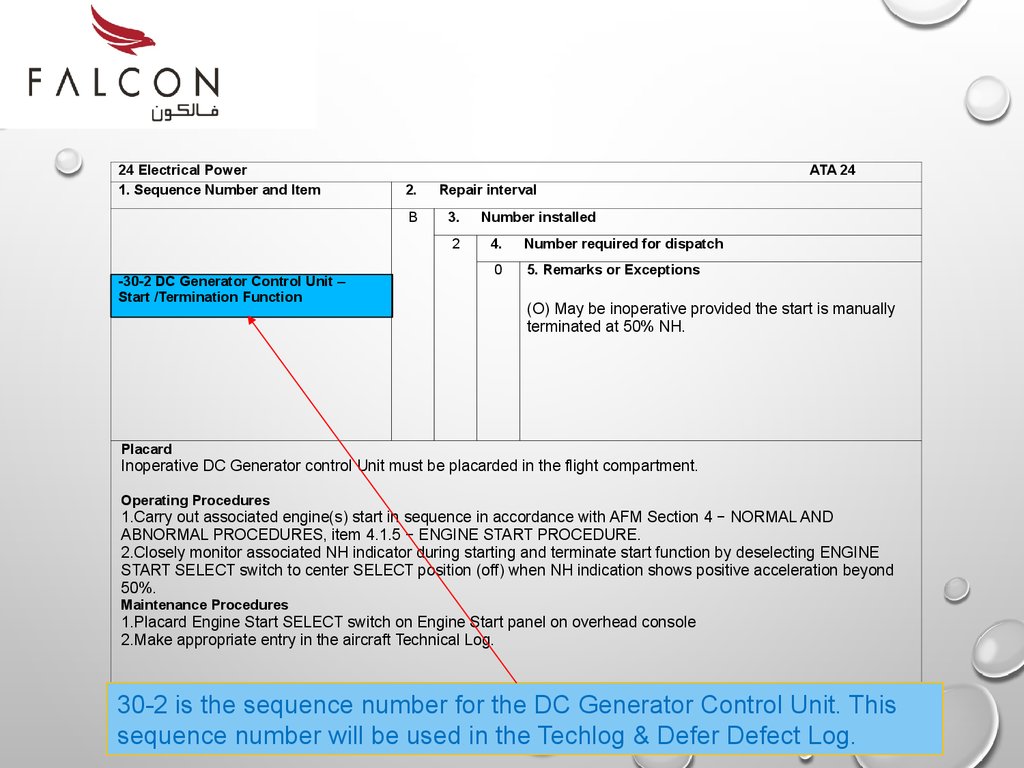
30-2 is the sequence number for the DC Generator Control Unit. This
sequence number will be used in the Techlog & Defer Defect Log.
38.
24 Electrical Power1. Sequence Number and Item
ATA 24
2.
B
Repair interval
3.
2
-30-2 DC Generator Control Unit –
Start /Termination Function
Number installed
4.
Number required for dispatch
0
5. Remarks or Exceptions
(O) May be inoperative provided the start is manually
terminated at 50% NH.
Placard
Inoperative DC Generator control Unit must be placarded in the flight compartment.
Operating Procedures
1.Carry out associated engine(s) start in sequence in accordance with AFM Section 4 − NORMAL AND
ABNORMAL PROCEDURES, item 4.1.5 − ENGINE START PROCEDURE.
2.Closely monitor associated NH indicator during starting and terminate start function by deselecting ENGINE
START SELECT switch to center SELECT position (off) when NH indication shows positive acceleration beyond
50%.
Maintenance Procedures
1.Placard Engine Start SELECT switch on Engine Start panel on overhead console
2.Make appropriate entry in the aircraft Technical Log.
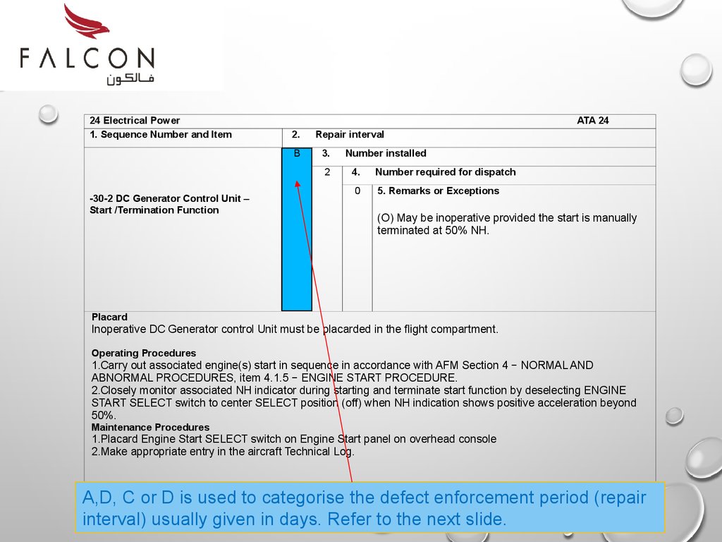
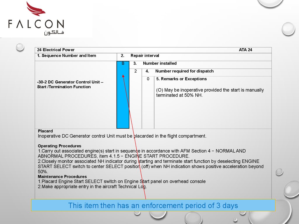
A,D, C or D is used to categorise the defect enforcement period (repair
interval) usually given in days. Refer to the next slide.
39.
24 Electrical Power1. Sequence Number and Item
ATA 24
2.
B
Repair interval
3.
2
-30-2 DC Generator Control Unit –
Start /Termination Function
Number installed
4.
Number required for dispatch
0
5. Remarks or Exceptions
(O) May be inoperative provided the start is manually
terminated at 50% NH.
Placard
Inoperative DC Generator control Unit must be placarded in the flight compartment.
Operating Procedures
1.Carry out associated engine(s) start in sequence in accordance with AFM Section 4 − NORMAL AND
ABNORMAL PROCEDURES, item 4.1.5 − ENGINE START PROCEDURE.
2.Closely monitor associated NH indicator during starting and terminate start function by deselecting ENGINE
START SELECT switch to center SELECT position (off) when NH indication shows positive acceleration beyond
50%.
Maintenance Procedures
1.Placard Engine Start SELECT switch on Engine Start panel on overhead console
2.Make appropriate entry in the aircraft Technical Log.
This item then has an enforcement period of 3 days
40.
24 Electrical Power1. Sequence Number and Item
ATA 24
2.
B
Repair interval
3.
2
-30-2 DC Generator Control Unit –
Start /Termination Function
Number installed
4.
Number required for dispatch
0
5. Remarks or Exceptions
(O) May be inoperative provided the start is manually
terminated at 50% NH.
Placard
Inoperative DC Generator control Unit must be placarded in the flight compartment.
Operating Procedures
1.Carry out associated engine(s) start in sequence in accordance with AFM Section 4 − NORMAL AND
ABNORMAL PROCEDURES, item 4.1.5 − ENGINE START PROCEDURE.
2.Closely monitor associated NH indicator during starting and terminate start function by deselecting ENGINE
START SELECT switch to center SELECT position (off) when NH indication shows positive acceleration beyond
50%.
Maintenance Procedures
1.Placard Engine Start SELECT switch on Engine Start panel on overhead console
2.Make appropriate entry in the aircraft Technical Log.
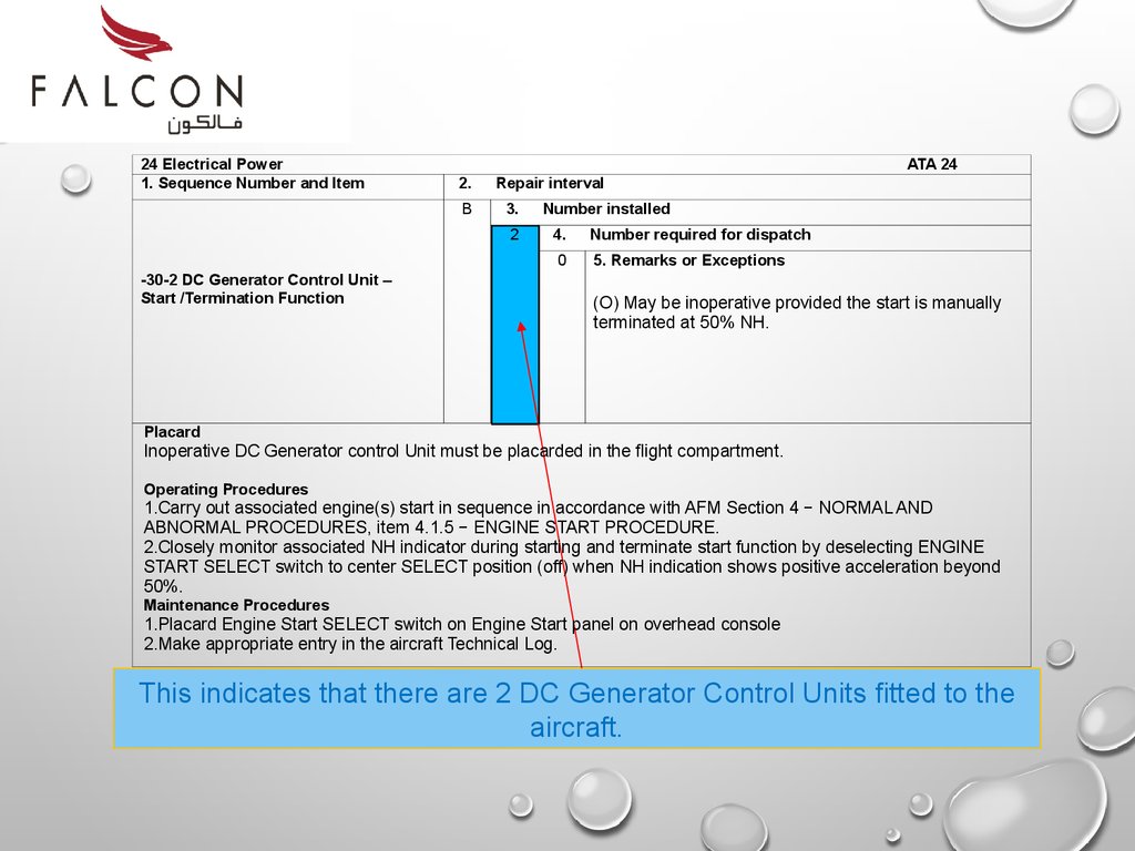
This indicates that there are 2 DC Generator Control Units fitted to the
aircraft.
41.
24 Electrical Power1. Sequence Number and Item
ATA 24
2.
B
Repair interval
3.
2
-30-2 DC Generator Control Unit –
Start /Termination Function
Number installed
4.
Number required for dispatch
0
5. Remarks or Exceptions
(O) May be inoperative provided the start is manually
terminated at 50% NH.
Placard
Inoperative DC Generator control Unit must be placarded in the flight compartment.
Operating Procedures
1.Carry out associated engine(s) start in sequence in accordance with AFM Section 4 − NORMAL AND
ABNORMAL PROCEDURES, item 4.1.5 − ENGINE START PROCEDURE.
2.Closely monitor associated NH indicator during starting and terminate start function by deselecting ENGINE
START SELECT switch to center SELECT position (off) when NH indication shows positive acceleration beyond
50%.
Maintenance Procedures
1.Placard Engine Start SELECT switch on Engine Start panel on overhead console
2.Make appropriate entry in the aircraft Technical Log.
This indicates that the aircraft can be airworthy with inoperable DC
Generator Control Units as long as the operating procedures are
compiled with
42.
24 Electrical Power1. Sequence Number and Item
ATA 24
2.
B
Repair interval
3.
2
-30-2 DC Generator Control Unit –
Start /Termination Function
Number installed
4.
Number required for dispatch
0
5. Remarks or Exceptions
(O) May be inoperative provided the start is manually
terminated at 50% NH.
Placard
Inoperative DC Generator control Unit must be placarded in the flight compartment.
Operating Procedures
1.Carry out associated engine(s) start in sequence in accordance with AFM Section 4 − NORMAL AND
ABNORMAL PROCEDURES, item 4.1.5 − ENGINE START PROCEDURE.
2.Closely monitor associated NH indicator during starting and terminate start function by deselecting ENGINE
START SELECT switch to center SELECT position (off) when NH indication shows positive acceleration beyond
50%.
Maintenance Procedures
1.Placard Engine Start SELECT switch on Engine Start panel on overhead console
2.Make appropriate entry in the aircraft Technical Log.
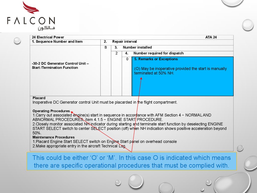
This could be either ‘O’ or ‘M’. In this case O is indicated which means
there are specific operational procedures that must be complied with.
43.
24 Electrical Power1. Sequence Number and Item
ATA 24
2.
B
Repair interval
3.
2
-30-2 DC Generator Control Unit –
Start /Termination Function
Number installed
4.
Number required for dispatch
0
5. Remarks or Exceptions
(O) May be inoperative provided the start is manually
terminated at 50% NH.
Placard
Inoperative DC Generator control Unit must be placarded in the flight compartment.
Operating Procedures
1.Carry out associated engine(s) start in sequence in accordance with AFM Section 4 − NORMAL AND
ABNORMAL PROCEDURES, item 4.1.5 − ENGINE START PROCEDURE.
2.Closely monitor associated NH indicator during starting and terminate start function by deselecting ENGINE
START SELECT switch to center SELECT position (off) when NH indication shows positive acceleration beyond
50%.
Maintenance Procedures
1.Placard Engine Start SELECT switch on Engine Start panel on overhead console
2.Make appropriate entry in the aircraft Technical Log.
This could be either ‘O’ or ‘M’. In this case O is indicated which means
there are specific operational procedures that must be complied with.
44.
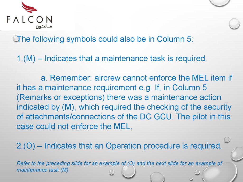
The following symbols could also be in Column 5:1.(M) – Indicates that a maintenance task is required.
a. Remember: aircrew cannot enforce the MEL item if
it has a maintenance requirement e.g. If, in Column 5
(Remarks or exceptions) there was a maintenance action
indicated by (M), which required the checking of the security
of attachments/connections of the DC GCU. The pilot in this
case could not enforce the MEL.
2.(O) – Indicates that an Operation procedure is required.
Refer to the preceding slide for an example of (O) and the next slide for an example of
maintenance task (M).
45.
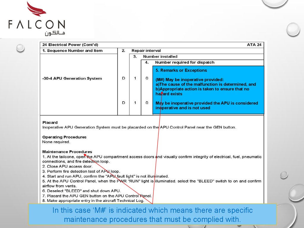
5. Remarks or Exceptions(M#) May be inoperative provided:
a)The cause of the malfunction is determined, and
b)Appropriate action is taken to ensure that no
hazard exists
May be inoperative provided the APU is considered
inoperative and is not used
In this case ‘M#’ is indicated which means there are specific
maintenance procedures that must be complied with.
46.
When a hash sign ‘#’ is indicated in column 5, then thesystem which is inoperative must be placarded. This
makes it obvious to the pilot and/or engineer that the
system is inoperative and a MEL is enforced.
Placards are supplied in the aircraft document bag.
47.
The Techlog Entry48.
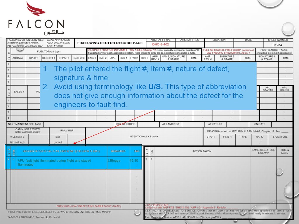
012341. The pilot entered the flight #, Item #, nature of defect,
signature & time
2. Avoid using terminology like U/S. This type of abbreviation
does not give enough information about the defect for the
engineers to fault find.
APU fault light illuminated during flight and stayed
illuminated
J.Bloggs
16:30
49.
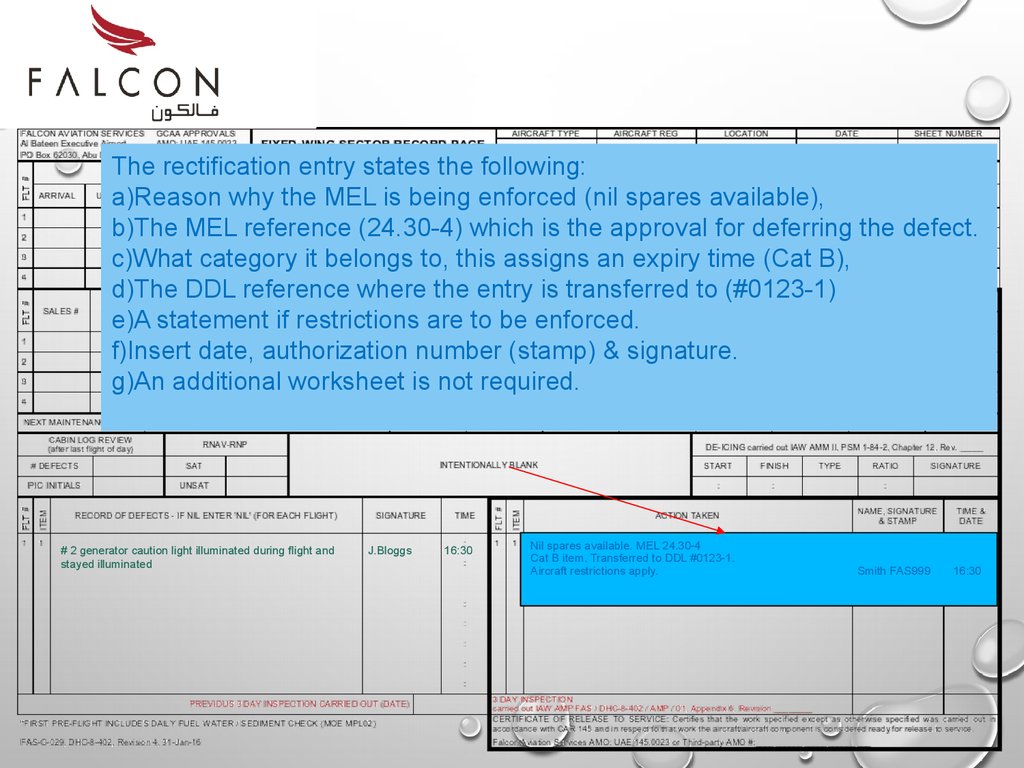
The rectification entry states the following:a)Reason why the MEL is being enforced (nil spares available),
b)The MEL reference (24.30-4) which is the approval for deferring the defect.
c)What category it belongs to, this assigns an expiry time (Cat B),
d)The DDL reference where the entry is transferred to (#0123-1)
e)A statement if restrictions are to be enforced.
f)Insert date, authorization number (stamp) & signature.
g)An additional worksheet is not required.
# 2 generator caution light illuminated during flight and
stayed illuminated
J.Bloggs
16:30
Nil spares available. MEL 24.30-4
Cat B item. Transferred to DDL #0123-1.
Aircraft restrictions apply.
Smith FAS999
16:30
50.
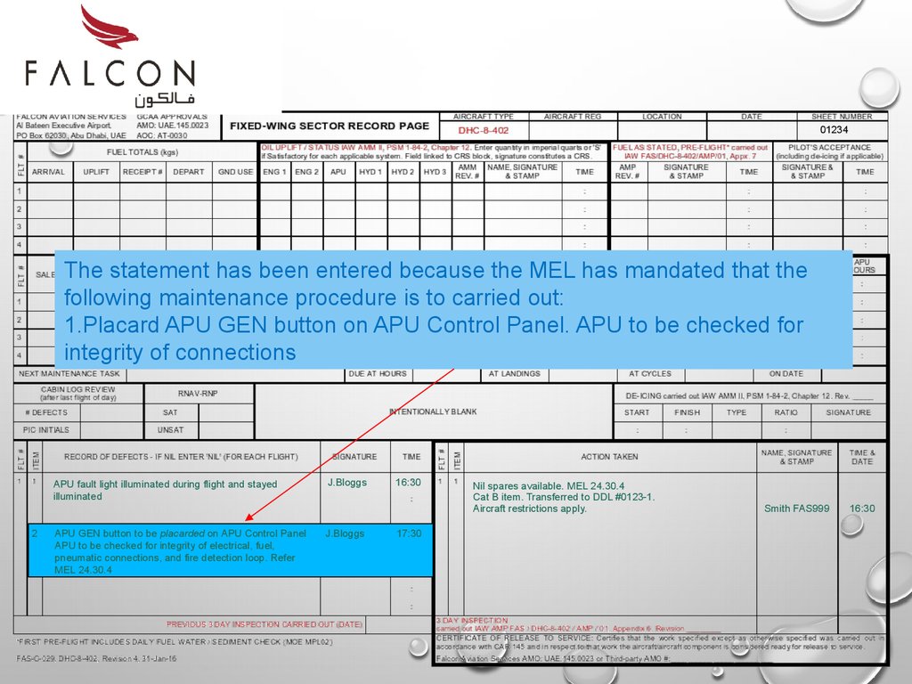
01234The statement has been entered because the MEL has mandated that the
following maintenance procedure is to carried out:
1.Placard APU GEN button on APU Control Panel. APU to be checked for
integrity of connections
APU fault light illuminated during flight and stayed
illuminated
2
APU GEN button to be placarded on APU Control Panel
APU to be checked for integrity of electrical, fuel,
pneumatic connections, and fire detection loop. Refer
MEL 24.30.4
J.Bloggs
J.Bloggs
16:30
17:30
Nil spares available. MEL 24.30.4
Cat B item. Transferred to DDL #0123-1.
Aircraft restrictions apply.
Smith FAS999
16:30
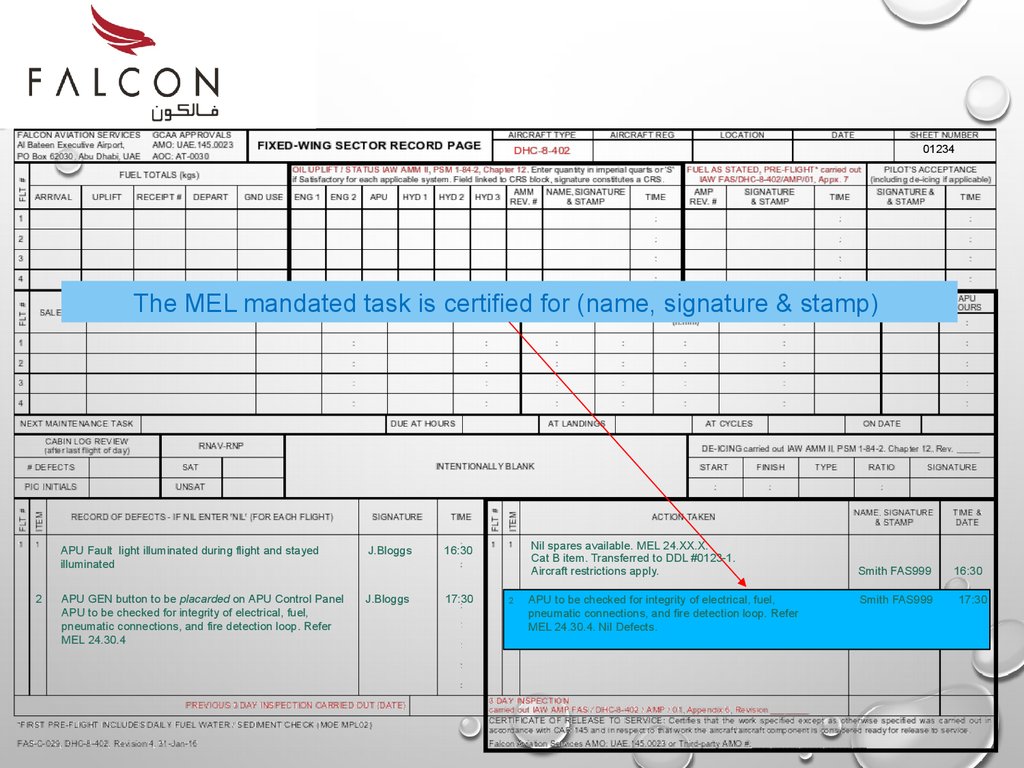
51.
01234The MEL mandated task is certified for (name, signature & stamp)
2
APU Fault light illuminated during flight and stayed
illuminated
J.Bloggs
APU GEN button to be placarded on APU Control Panel
APU to be checked for integrity of electrical, fuel,
pneumatic connections, and fire detection loop. Refer
MEL 24.30.4
J.Bloggs
Nil spares available. MEL 24.XX.X.
Cat B item. Transferred to DDL #0123-1.
Aircraft restrictions apply.
16:30
17:30
2
APU to be checked for integrity of electrical, fuel,
pneumatic connections, and fire detection loop. Refer
MEL 24.30.4. Nil Defects.
Smith FAS999
Smith FAS999
16:30
17:30
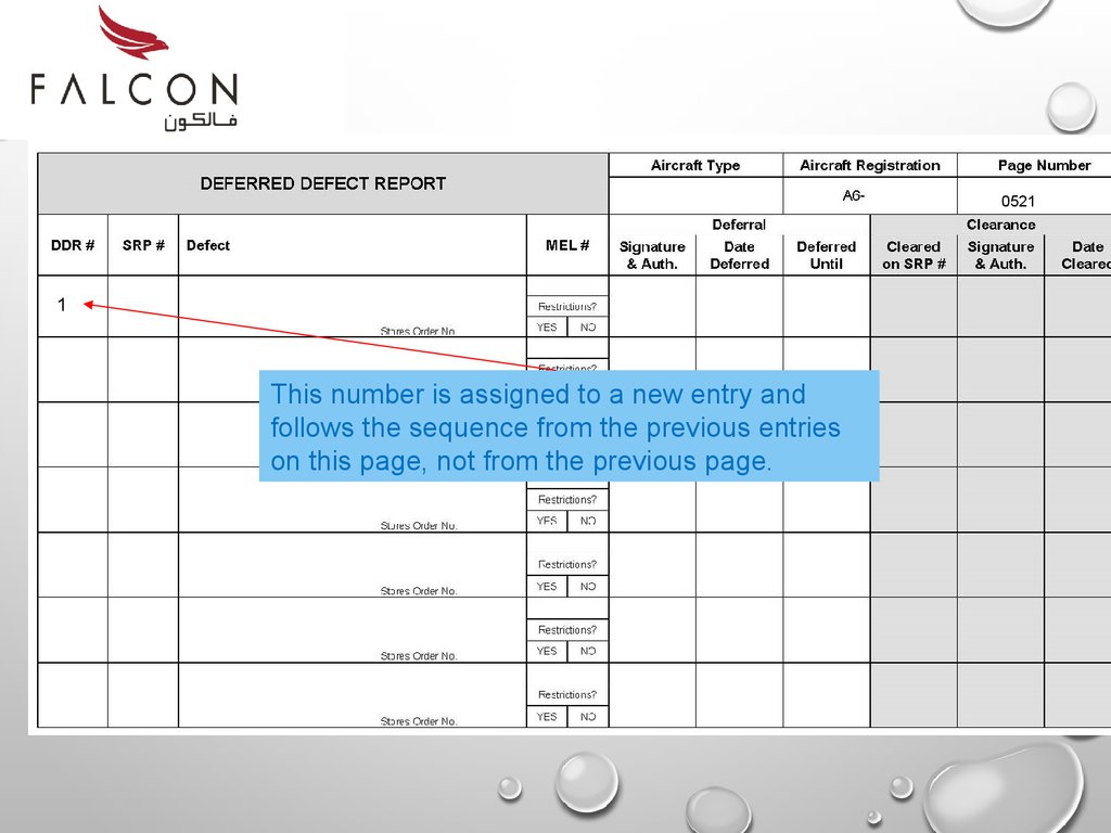
52.
05211
This number is assigned to a new entry and
follows the sequence from the previous entries
on this page, not from the previous page.
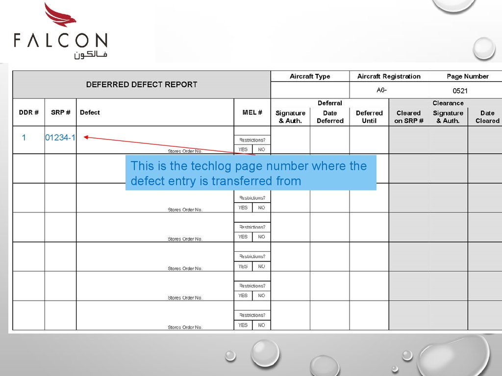
53.
05211
01234-1
This is the techlog page number where the
defect entry is transferred from
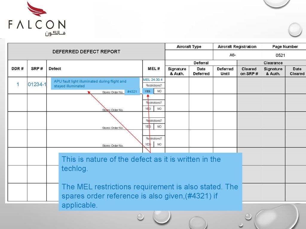
54.
05211
01234-1
MEL 24.30.4
APU fault light illuminated during flight and
stayed illuminated
#4321
YES
This is nature of the defect as it is written in the
techlog.
The MEL restrictions requirement is also stated. The
spares order reference is also given,(#4321) if
applicable.
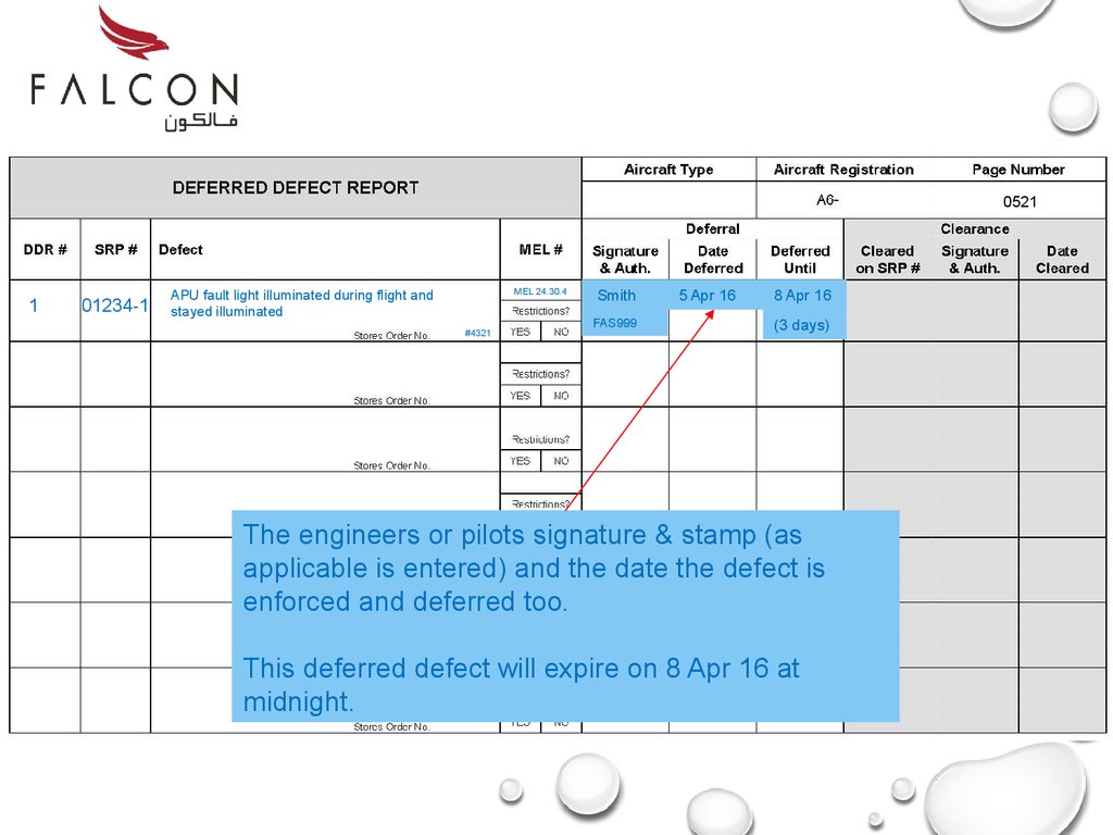
55.
05211
01234-1
MEL 24.30.4
APU fault light illuminated during flight and
stayed illuminated
#4321
Smith
FAS999
5 Apr 16
8 Apr 16
(3 days)
The engineers or pilots signature & stamp (as
applicable is entered) and the date the defect is
enforced and deferred too.
This deferred defect will expire on 8 Apr 16 at
midnight.
56.
Release to ServiceWhen the Techlog and deferred defect log entries
are completed the aircraft is then certified as being
‘Released to Service’.
The aircraft can now be flown.
Take note of any restrictions that have been
enforced.
57.
End of Part 358.
Defect RepairPart 4
59.
Defect Repair• When the spare part has arrived or when the
deferment date has expired, the defect must be
repaired.
• An extension can be granted but this process has to
go through the GCAA, this would take sometime and
also firm justification for requesting the extension will
be required. Lack of spares is not a suitable reason.
60.
Techlog EntriesThe part has been replaced and the
documentation now has to be completed.
This is shown on the following slides.
61.
05211
01234-1
MEL 24.30.4
APU fault light illuminated during flight and
stayed illuminated
#4321
Smith
5 Apr 16
8 Apr 16
01235-1
(3 days)
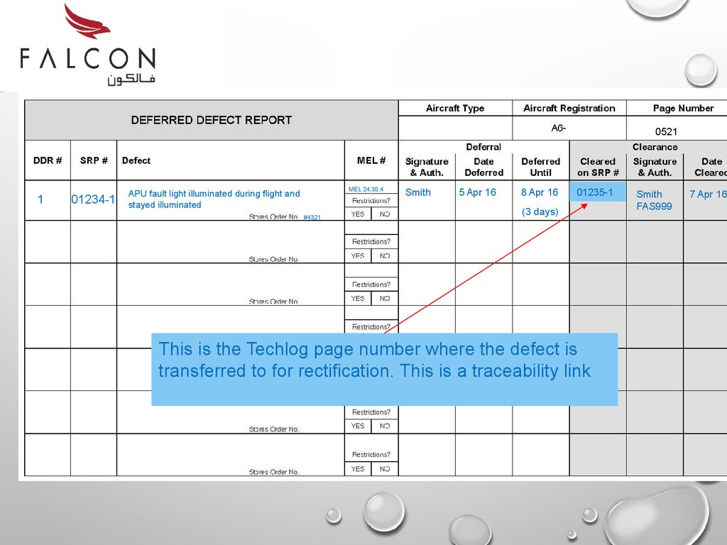
This is the Techlog page number where the defect is
transferred to for rectification. This is a traceability link
Smith
FAS999
7 Apr 16
62.
05211
01234-1
MEL 24.30.4
APU fault light illuminated during flight and
stayed illuminated
#4321
Smith
5 Apr 16
8 Apr 16
01235-1
(3 days)
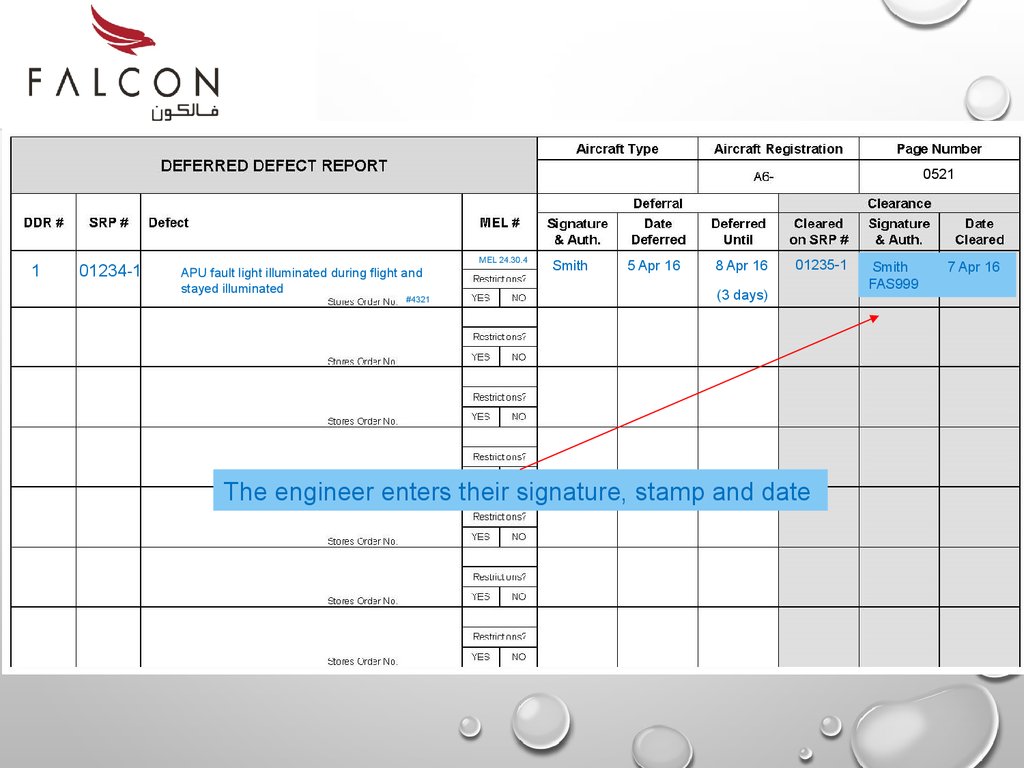
The engineer enters their signature, stamp and date
Smith
FAS999
7 Apr 16
63.
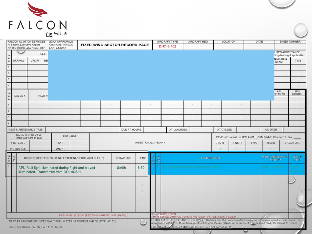
7 Apr 161. The nature of the defect is entered into the Techlog page.
2. - Note: the entry is written the same as the original entry.
3. The DDL number is also included. This gives traceability
where the defect originated. It also removes confusion of
multiple defect items
4. The date and engineers signature is entered.
APU fault light illuminated during flight and stayed
illuminated. Transferred from DDL #0521
J.Bloggs
16:30
01235
64.
APU fault light illuminated during flight and stayedilluminated. Transferred from DDL #0521
Smith
16:30
APU Replaced Ref: AMM 000000001
Smith FAS999
20:30
7 Apr 16
65.
66.
67.
68.
Point cursor on screen & double click to start.69.
End of Part 570.
This concludes theMINIMUM EQUIPMENT LIST
(MEL) TRAINING