


 Механика
Похожие презентации:


 Engine")
Engine E4T15C
1.
Engine E4T15C1
2.
CatalogEngine Introduction
E4T15C Engine- Mechanics
E4T15C Engine- Electronic
ControlEuro VI B Vehicle Emission
Standards And Malfunction
Diagnosis
Engine Immobilizer
2
3.
Part 1Engine
Introduction
3
4.
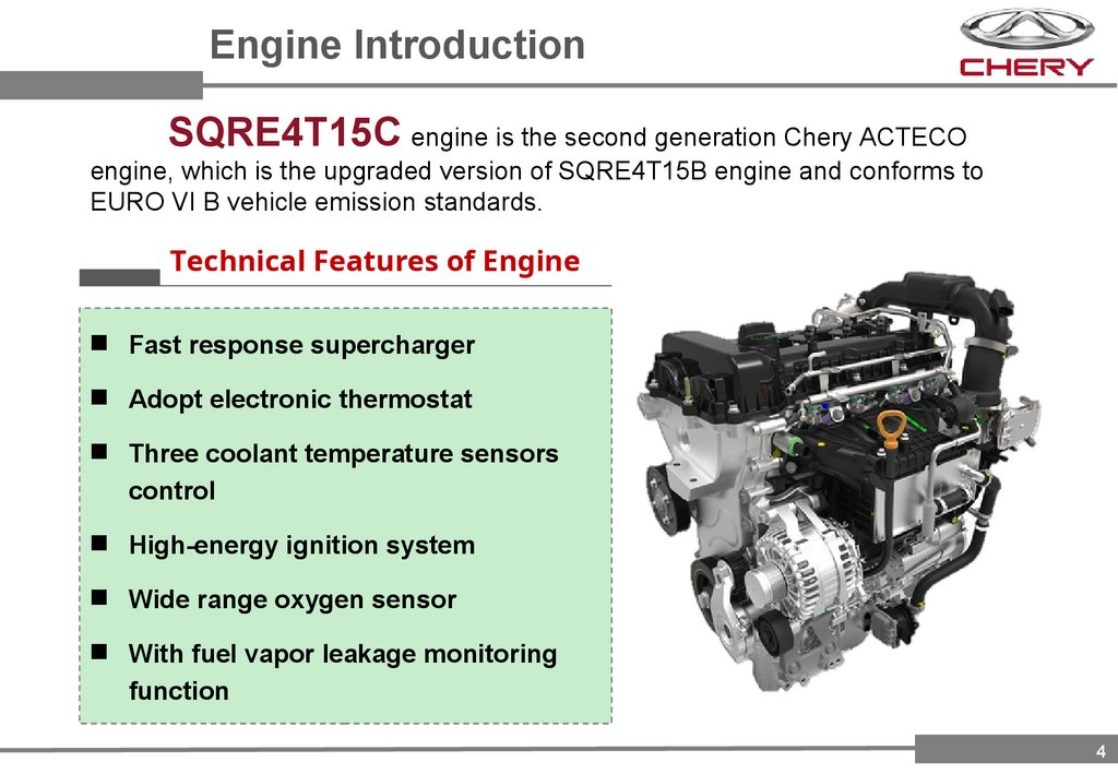
Engine IntroductionSQRE4T15C engine is the second generation Chery ACTECO
engine, which is the upgraded version of SQRE4T15B engine and conforms to
EURO VI B vehicle emission standards.
Technical Features of Engine
Fast response supercharger
Adopt electronic thermostat
Three coolant temperature sensors
control
High-energy ignition system
Wide range oxygen sensor
With fuel vapor leakage monitoring
function
4
5.
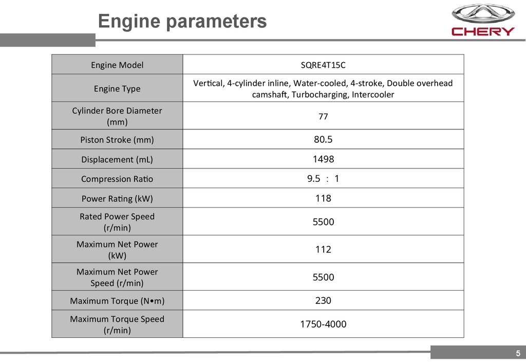
Engine parametersEngine Model
SQRE4T15C
Engine Type
Vertical, 4-cylinder inline, Water-cooled, 4-stroke, Double overhead
camshaft, Turbocharging, Intercooler
Cylinder Bore Diameter
(mm)
77
Piston Stroke (mm)
80.5
Displacement (mL)
1498
Compression Ratio
9.5 1
Power Rating (kW)
118
Rated Power Speed
(r/min)
5500
Maximum Net Power
(kW)
112
Maximum Net Power
Speed (r/min)
5500
Maximum Torque (N•m)
230
Maximum Torque Speed
(r/min)
1750-4000
5
6.
Part 2E4T15C engine
Mechanics
6
7.
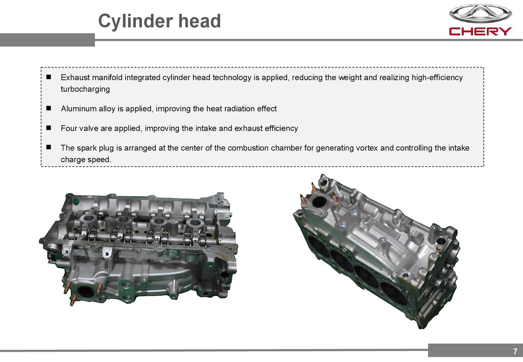
Cylinder headExhaust manifold integrated cylinder head technology is applied, reducing the weight and realizing high-efficiency
turbocharging
Aluminum alloy is applied, improving the heat radiation effect
Four valve are applied, improving the intake and exhaust efficiency
The spark plug is arranged at the center of the combustion chamber for generating vortex and controlling the intake
charge speed.
7
8.
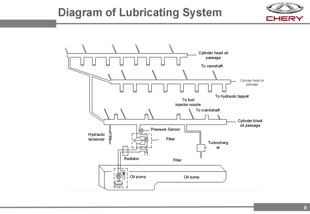
Diagram of Lubricating SystemCylinder head oil
passage
To camshaft
Cylinder head oil
passage
To hydraulic tappet
To fuel
injector nozzle
To crankshaft
Cylinder block
oil passage
Pressure Sensor
Hydraulic
tensioner
Filter
Radiator
Oil pump
Turbocharg
er
Filter
Oil sump
8
9.
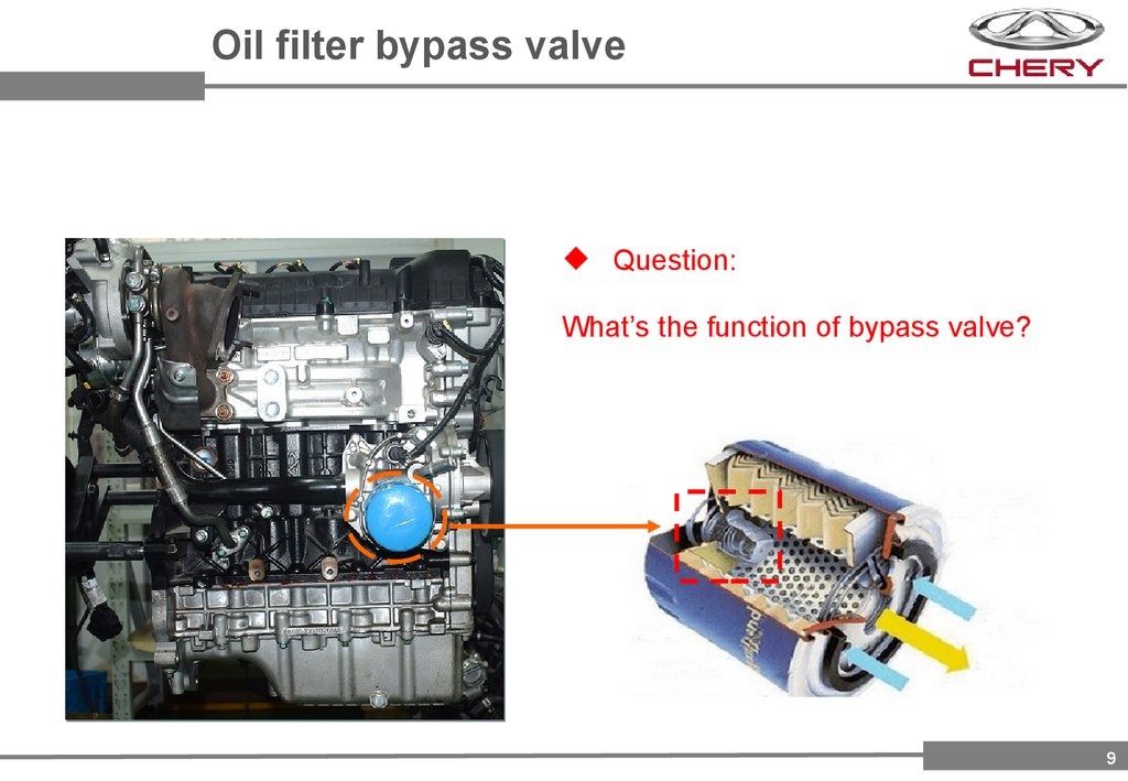
Oil filter bypass valveQuestion:
What’s the function of bypass valve?
9
10.
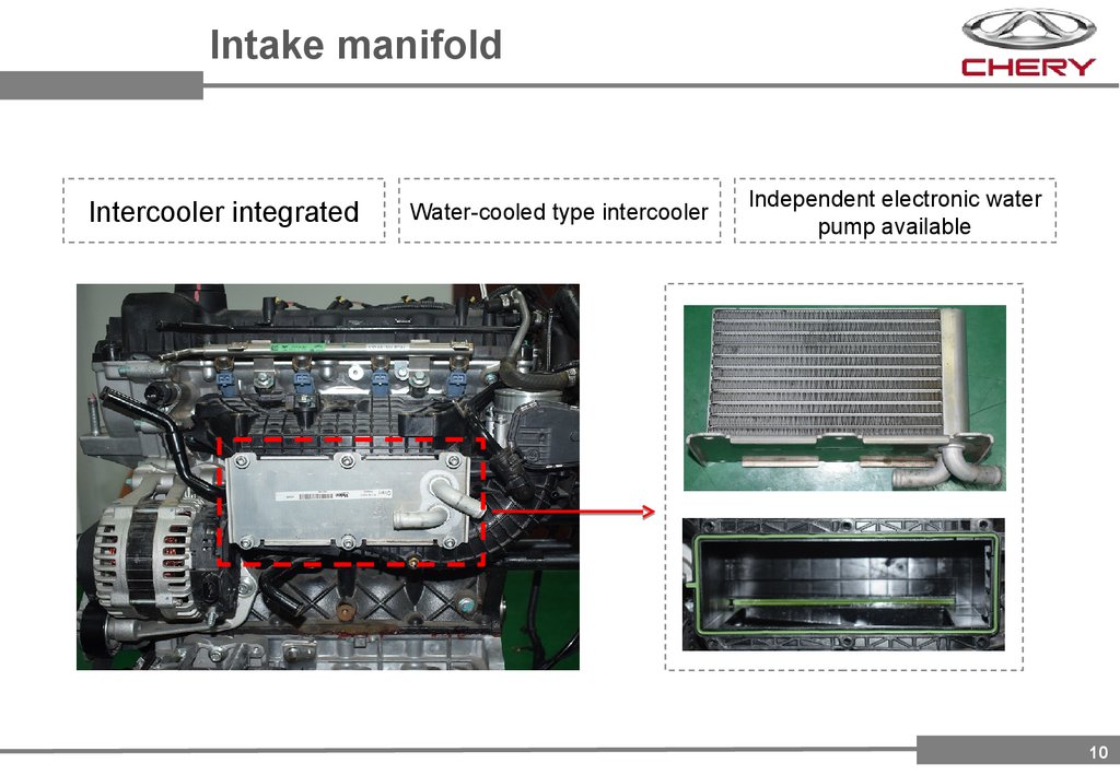
Intake manifoldIntercooler integrated
Water-cooled type intercooler
Independent electronic water
pump available
10
11.
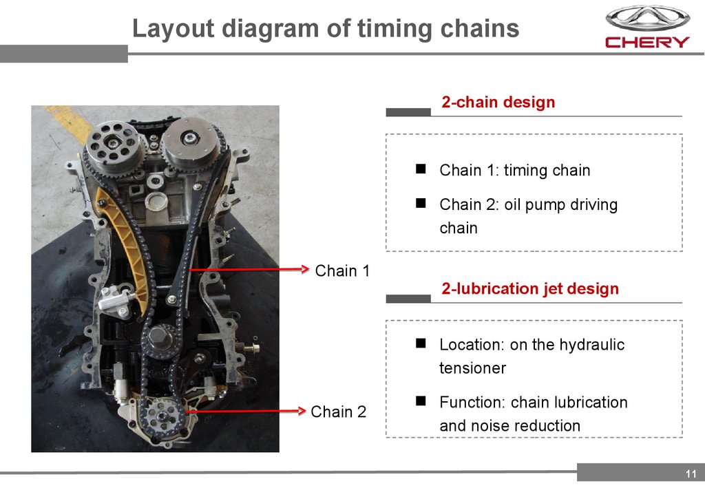
Layout diagram of timing chains2-chain design
Chain 1: timing chain
Chain 2: oil pump driving
chain
Chain 1
2-lubrication jet design
Location: on the hydraulic
tensioner
Chain 2
Function: chain lubrication
and noise reduction
11
12.
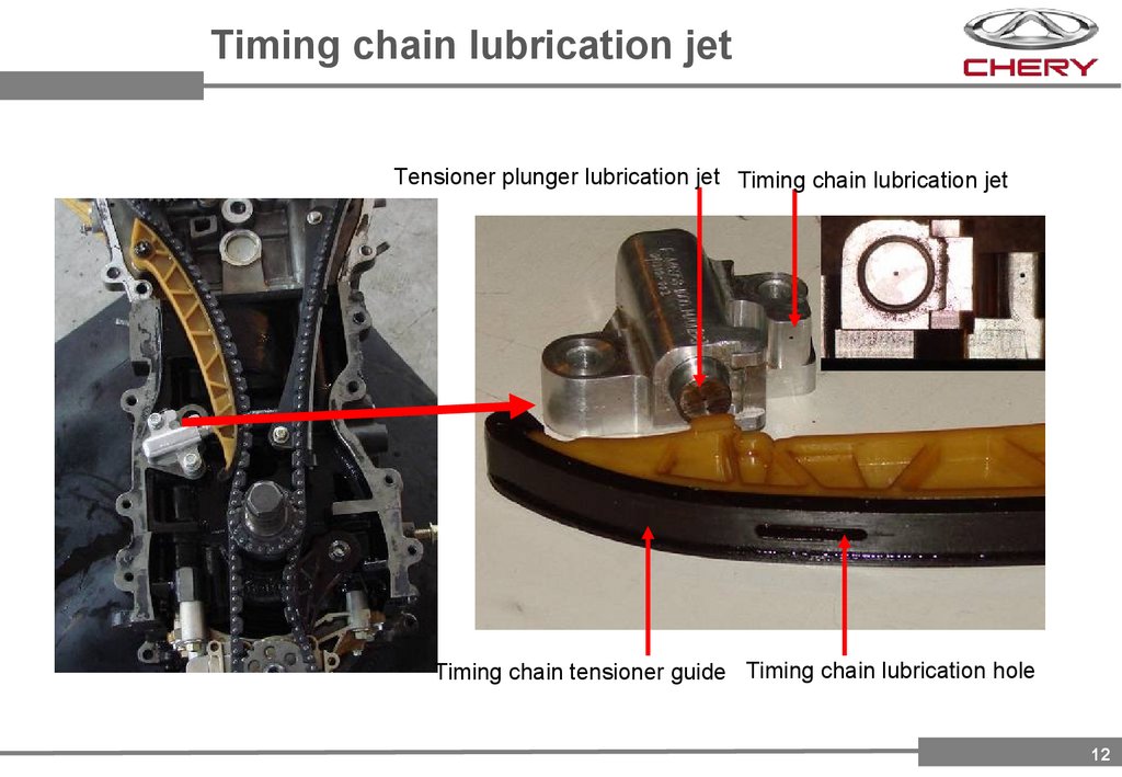
Timing chain lubrication jetTensioner plunger lubrication jet Timing chain lubrication jet
Timing chain tensioner guide Timing chain lubrication hole
12
13.
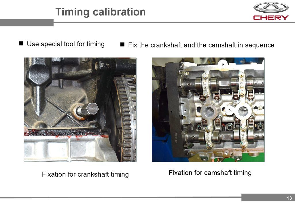
Timing calibrationUse special tool for timing
Fix the crankshaft and the camshaft in sequence
Fixation for crankshaft timing
Fixation for camshaft timing
13
14.
Part 3E4T15C engine
Electronic Control
14
15.
Electronic Control SystemSQRE4T15C engine electronic control system adopts combined electronic ME17U6.1.
Boost / intake / vacuum pressure signal
Main relay control
Boost / intake temperature signal
Fuel pump / A/C compressor relay
Electronic throttle position signal
Injection timing and injection duration
Accelerator pedal position signal
Electric water pump control
A/C pressure switch signal
Electronic throttle motor control
Intake / exhaust camshaft phase signal
Oxygen sensor heating control
Crankshaft rotation angle signal
Electric water pump feedback signal
Knock signal
Brake / clutch switch signal
Vehicle speed / A/C request signal
High speed / low speed cooling fan relay control
ECU
(ME17U6.1)
Canister solenoid valve
Intake / exhaust VVT actuator control
CAN
CAN
Engine speed output / malfunction indicator control
Upstream / downstream oxygen sensor signal
Supercharger exhaust control valve position signal
Ignition coil charging time and ignition advance angle
Canister desorption pressure signal
Turbocharger exhaust valve control
Fuel tank pressure signal
Coolant / inlet /outlet temperature signal
Canister close solenoid valve
Electronic thermostat control
15
16.
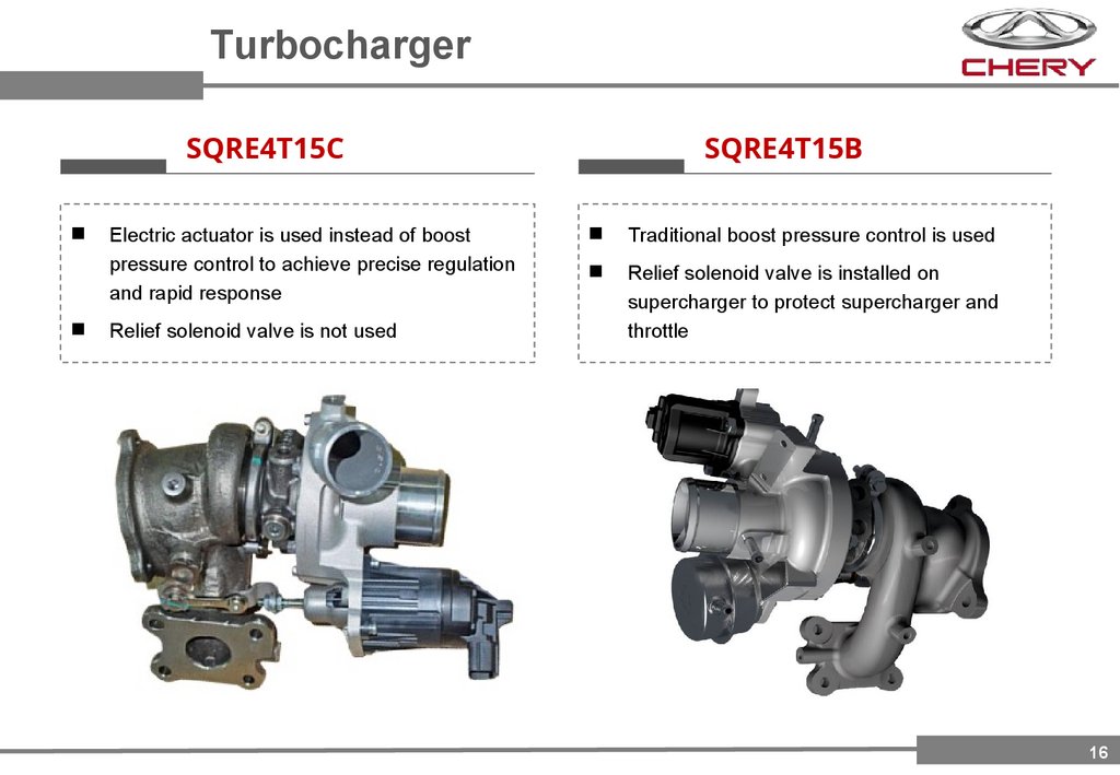
TurbochargerSQRE4T15C
Electric actuator is used instead of boost
pressure control to achieve precise regulation
and rapid response
Relief solenoid valve is not used
SQRE4T15B
Traditional boost pressure control is used
Relief solenoid valve is installed on
supercharger to protect supercharger and
throttle
16
17.
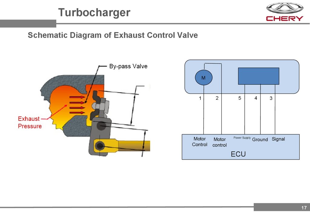
TurbochargerSchematic Diagram of Exhaust Control Valve
M
1
2
Motor
Control
Motor
control
5
Power Supply
4
3
Ground Signal
ECU
17
18.
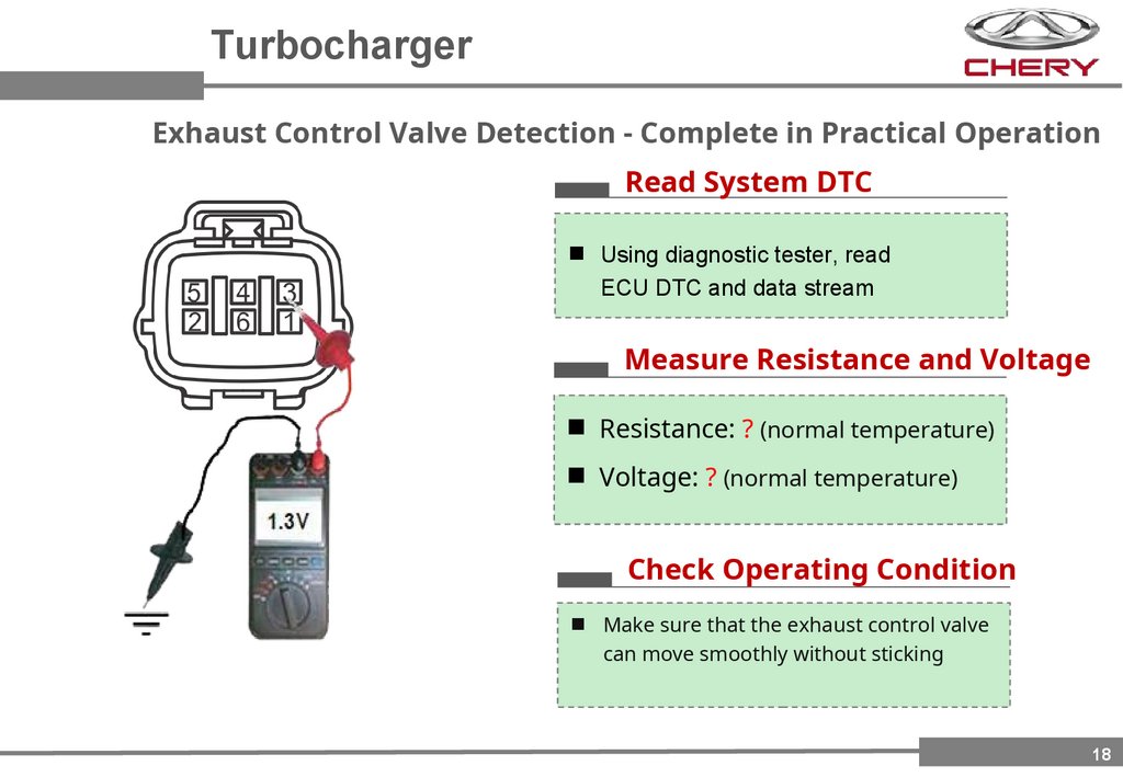
TurbochargerExhaust Control Valve Detection - Complete in Practical Operation
Read System DTC
Using diagnostic tester, read
ECU DTC and data stream
Measure Resistance and Voltage
Resistance: ? (normal temperature)
Voltage: ? (normal temperature)
Check Operating Condition
Make sure that the exhaust control valve
can move smoothly without sticking
18
19.
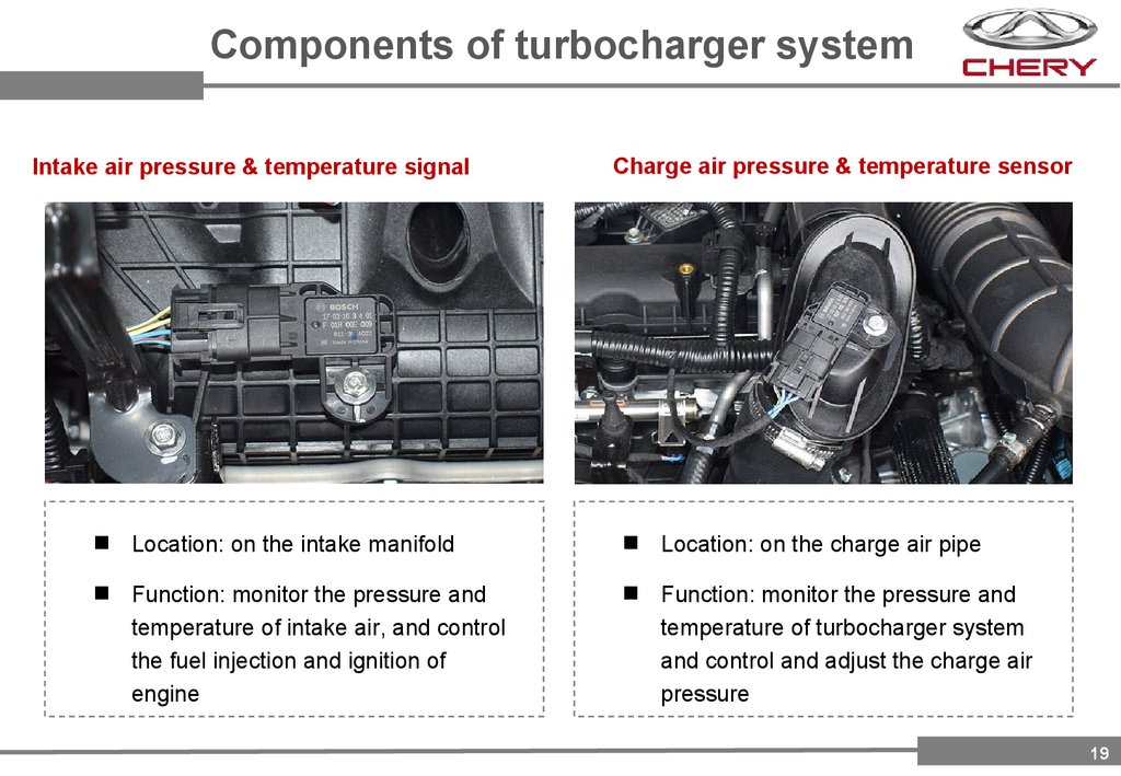
Components of turbocharger systemIntake air pressure & temperature signal
Charge air pressure & temperature sensor
Location: on the intake manifold
Location: on the charge air pipe
Function: monitor the pressure and
temperature of intake air, and control
the fuel injection and ignition of
engine
Function: monitor the pressure and
temperature of turbocharger system
and control and adjust the charge air
pressure
19
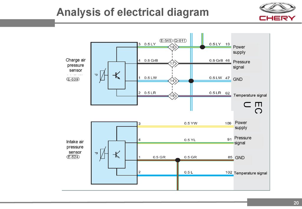
20.
Analysis of electrical diagramPower
supply
Charge air
pressure
sensor
Pressure
signal
GND
Temperature signal
EC
U
Power
supply
Intake air
pressure
sensor
Pressure
signal
GND
Temperature signal
20
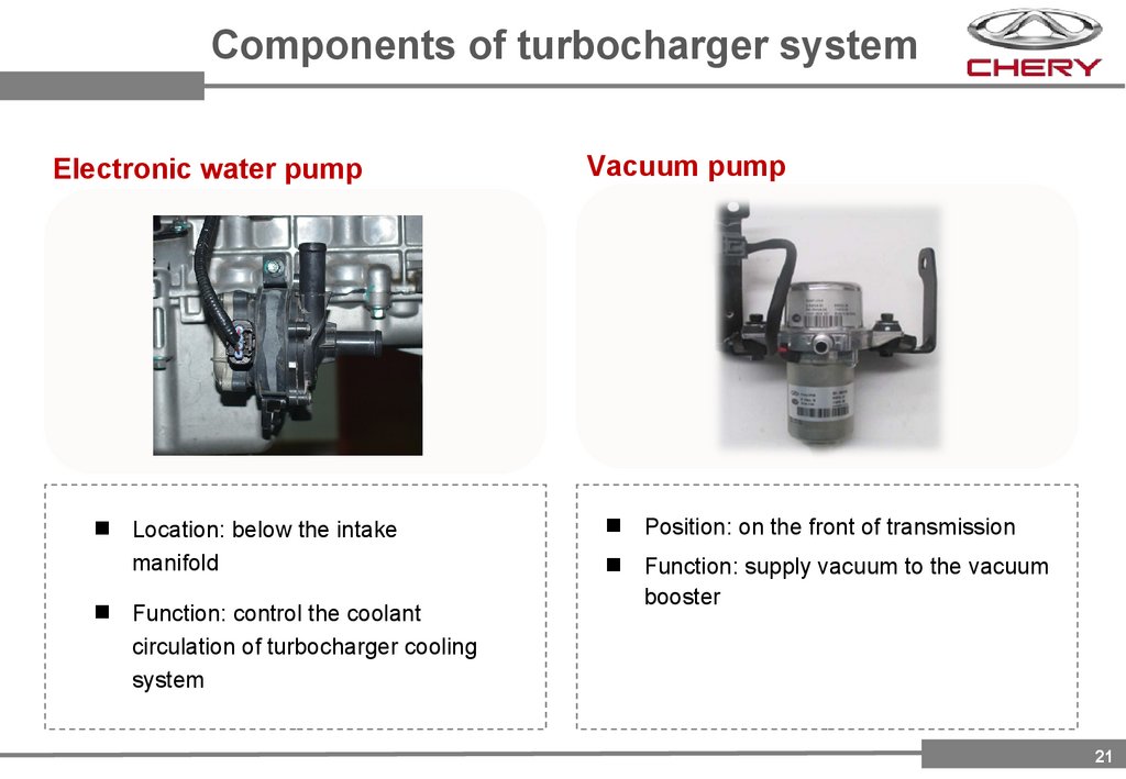
21.
Components of turbocharger systemElectronic water pump
Location: below the intake
manifold
Function: control the coolant
circulation of turbocharger cooling
system
Vacuum pump
Position: on the front of transmission
Function: supply vacuum to the vacuum
booster
21
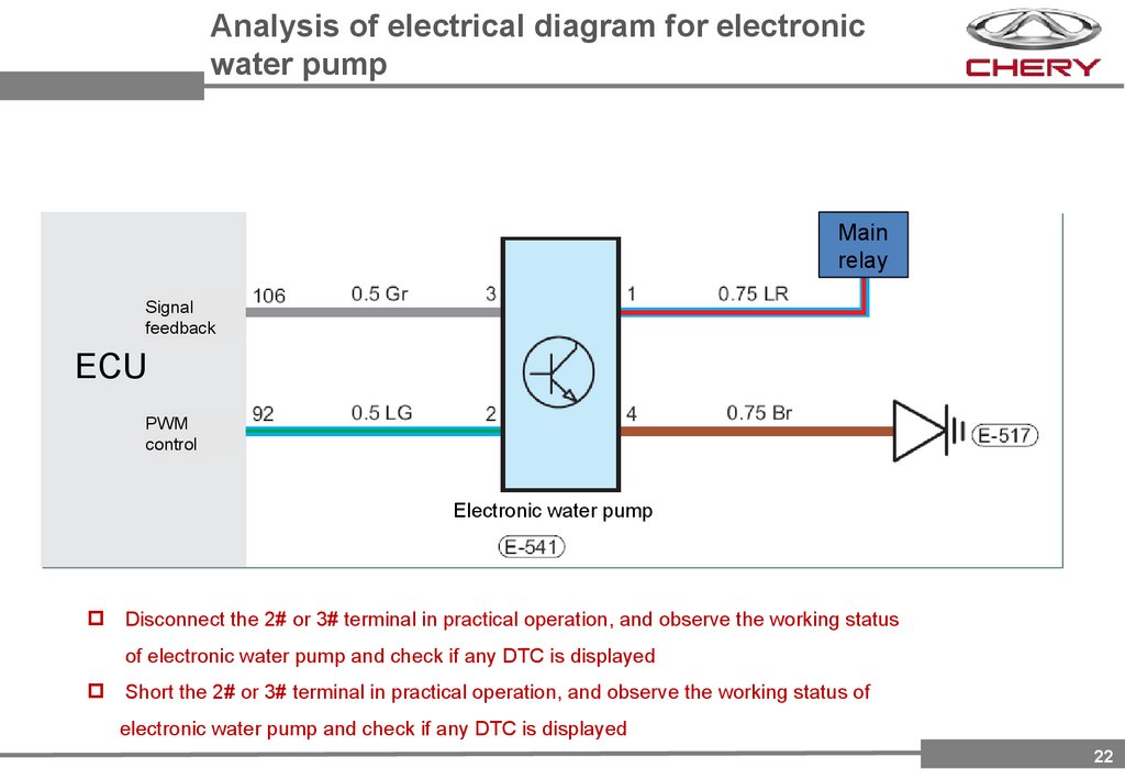
22.
Analysis of electrical diagram for electronicwater pump
Main
relay
Signal
feedback
ECU
PWM
control
Electronic water pump
Disconnect the 2# or 3# terminal in practical operation, and observe the working status
of electronic water pump and check if any DTC is displayed
Short the 2# or 3# terminal in practical operation, and observe the working status of
electronic water pump and check if any DTC is displayed
22
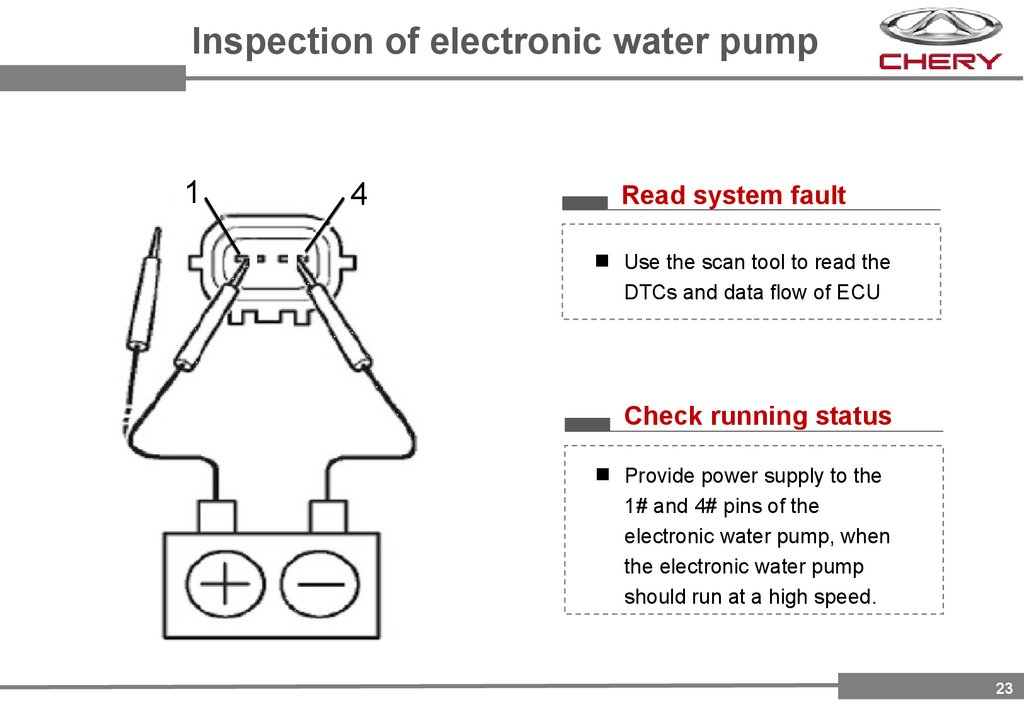
23.
Inspection of electronic water pump1
4
Read system fault
Use the scan tool to read the
DTCs and data flow of ECU
Check running status
Provide power supply to the
1# and 4# pins of the
electronic water pump, when
the electronic water pump
should run at a high speed.
23
24.
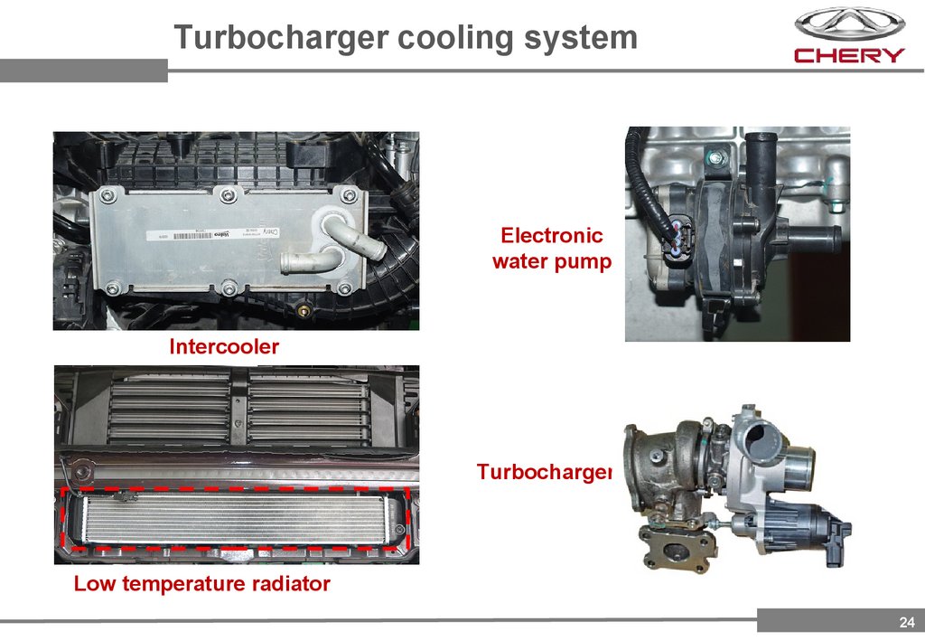
Turbocharger cooling systemElectronic
water pump
Intercooler
Turbocharger
Low temperature radiator
24
25.
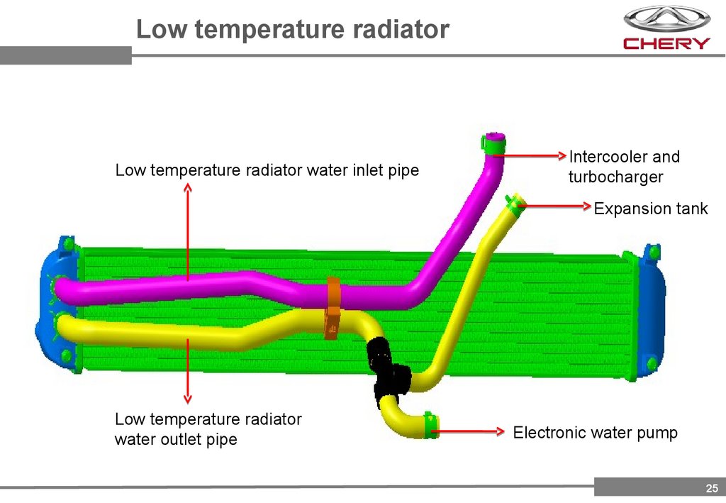
Low temperature radiatorLow temperature radiator water inlet pipe
Intercooler and
turbocharger
Expansion tank
Low temperature radiator
water outlet pipe
Electronic water pump
25
26.
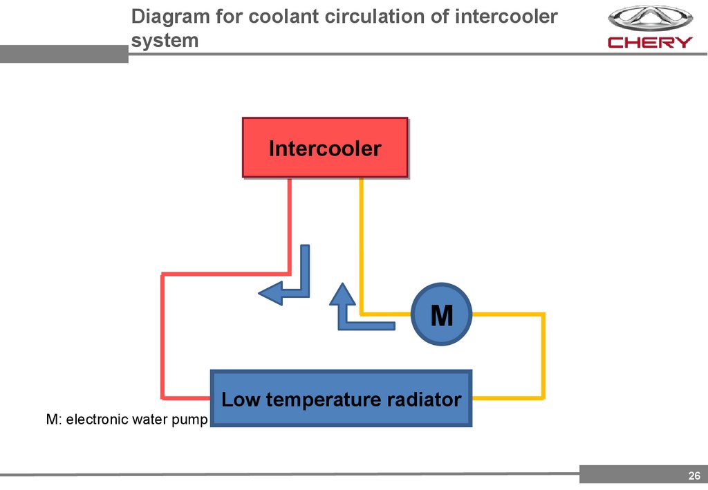
Diagram for coolant circulation of intercoolersystem
Intercooler
M
Low temperature radiator
M: electronic water pump
26
27.
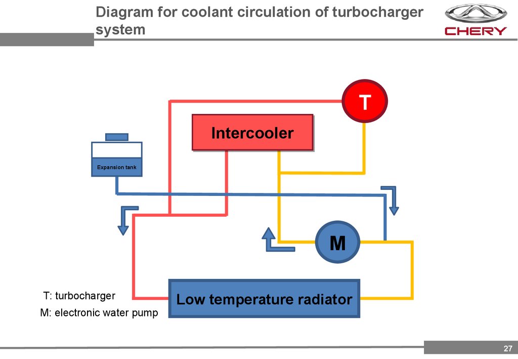
Diagram for coolant circulation of turbochargersystem
T
Intercooler
Expansion tank
M
T: turbocharger
M: electronic water pump
Low temperature radiator
27
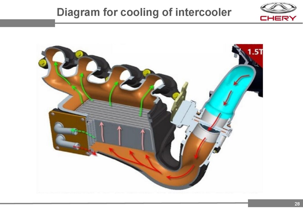
28.
Diagram for cooling of intercooler28
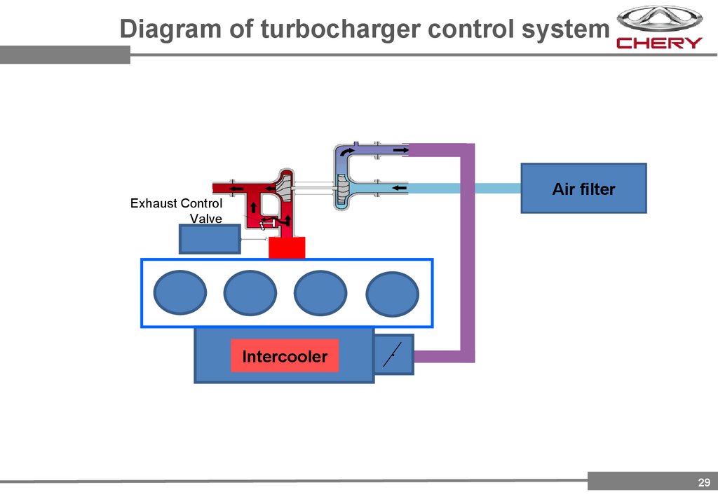
29.
Diagram of turbocharger control systemAir filter
Exhaust Control
Valve
Intercooler
.
29
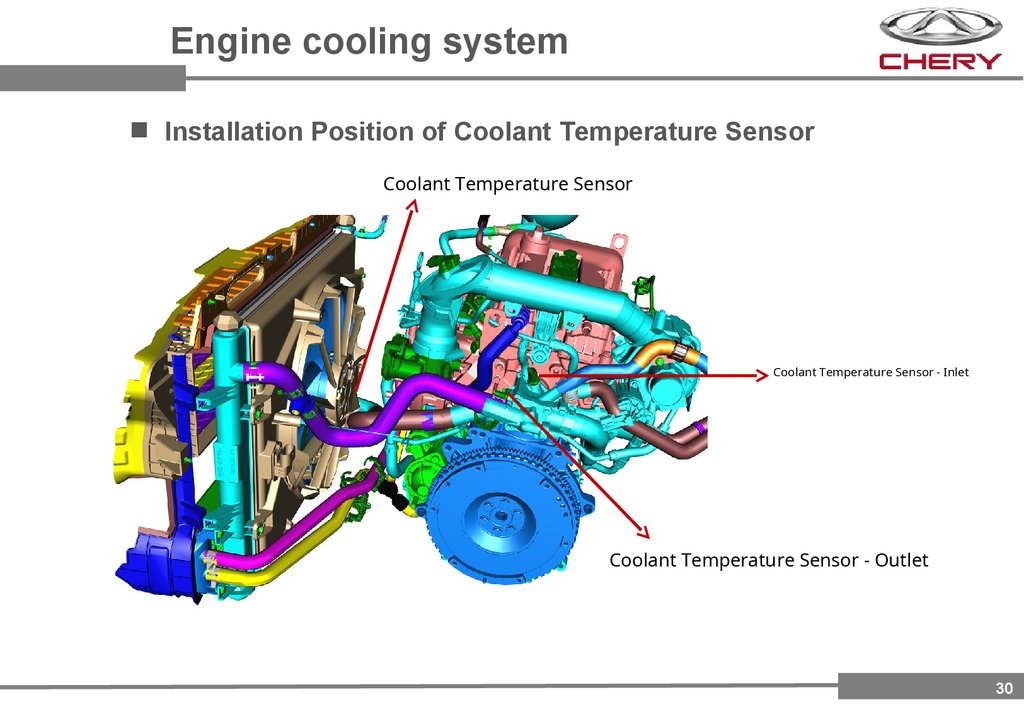
30.
Engine cooling systemInstallation Position of Coolant Temperature Sensor
Coolant Temperature Sensor
Coolant Temperature Sensor - Inlet
Coolant Temperature Sensor - Outlet
30
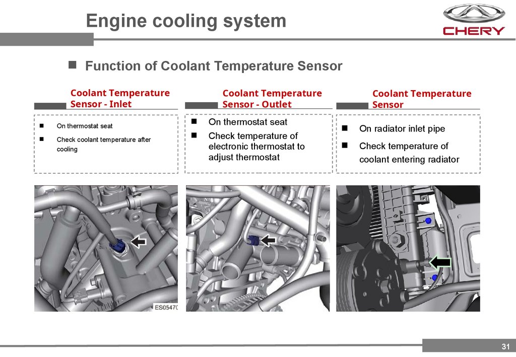
31.
Engine cooling systemFunction of Coolant Temperature Sensor
Coolant Temperature
Sensor - Inlet
On thermostat seat
Check coolant temperature after
cooling
Coolant Temperature
Sensor - Outlet
On thermostat seat
Check temperature of
electronic thermostat to
adjust thermostat
Coolant Temperature
Sensor
On radiator inlet pipe
Check temperature of
coolant entering radiator
31
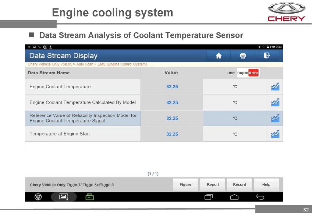
32.
Engine cooling systemData Stream Analysis of Coolant Temperature Sensor
32
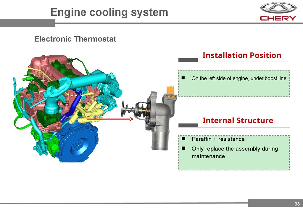
33.
Engine cooling systemElectronic Thermostat
Installation Position
On the left side of engine, under boost line
Internal Structure
Paraffin + resistance
Only replace the assembly during
maintenance
33
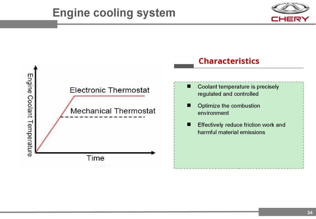
34.
Engine cooling systemCharacteristics
Coolant temperature is precisely
regulated and controlled
Optimize the combustion
environment
Effectively reduce friction work and
harmful material emissions
34
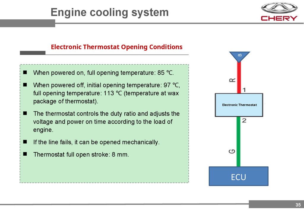
35.
Engine cooling systemB
Electronic Thermostat Opening Conditions
When powered on, full opening temperature: 85 ℃.
When powered off, initial opening temperature: 97 ℃,
full opening temperature: 113 ℃ (temperature at wax
package of thermostat).
Electronic Thermostat
The thermostat controls the duty ratio and adjusts the
voltage and power on time according to the load of
engine.
If the line fails, it can be opened mechanically.
Thermostat full open stroke: 8 mm.
ECU
35
36.
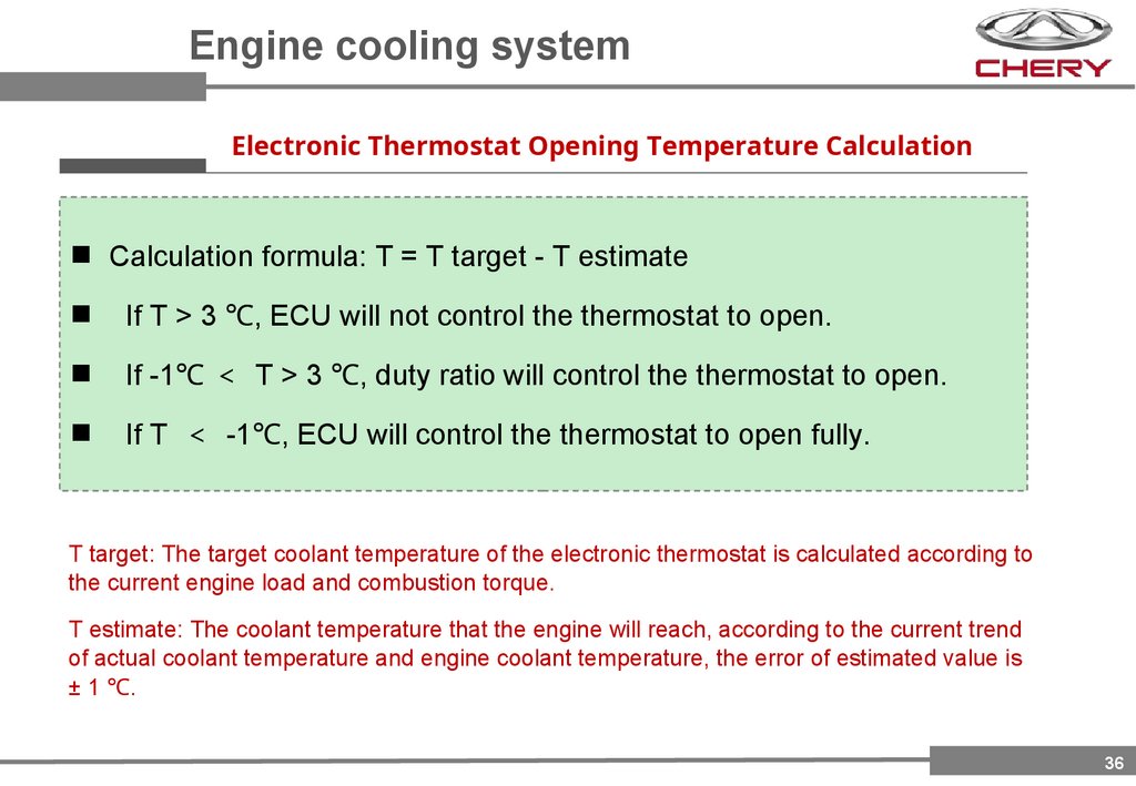
Engine cooling systemElectronic Thermostat Opening Temperature Calculation
Calculation formula: T = T target - T estimate
If T > 3 ℃, ECU will not control the thermostat to open.
If -1℃ T > 3 ℃, duty ratio will control the thermostat to open.
If T -1℃, ECU will control the thermostat to open fully.
T target: The target coolant temperature of the electronic thermostat is calculated according to
the current engine load and combustion torque.
T estimate: The coolant temperature that the engine will reach, according to the current trend
of actual coolant temperature and engine coolant temperature, the error of estimated value is
± 1 ℃.
36
37.
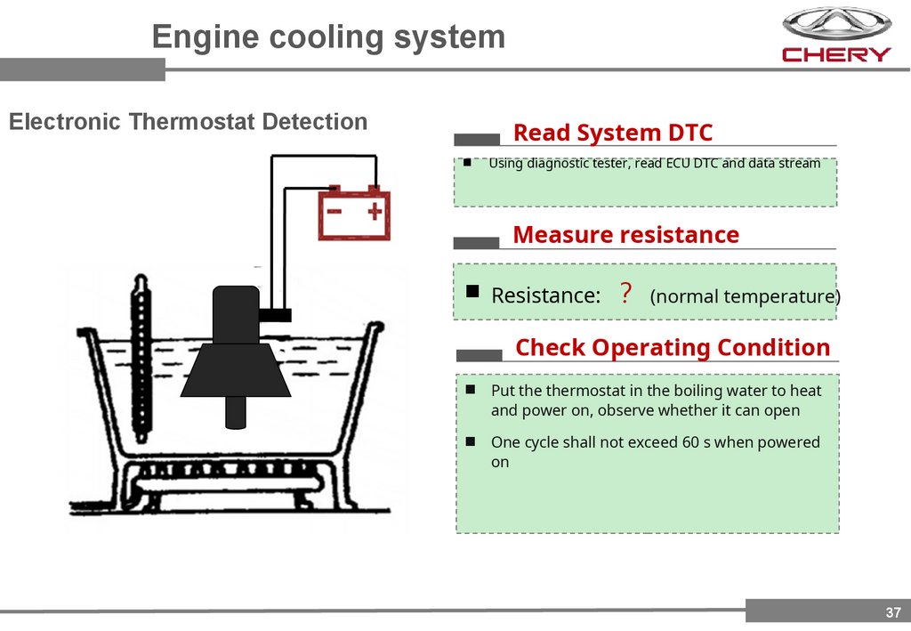
Engine cooling systemElectronic Thermostat Detection
Read System DTC
Using diagnostic tester, read ECU DTC and data stream
Measure resistance
Resistance: (normal temperature)
Check Operating Condition
Put the thermostat in the boiling water to heat
and power on, observe whether it can open
One cycle shall not exceed 60 s when powered
on
37
38.
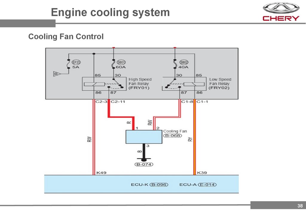
Engine cooling systemCooling Fan Control
38
39.
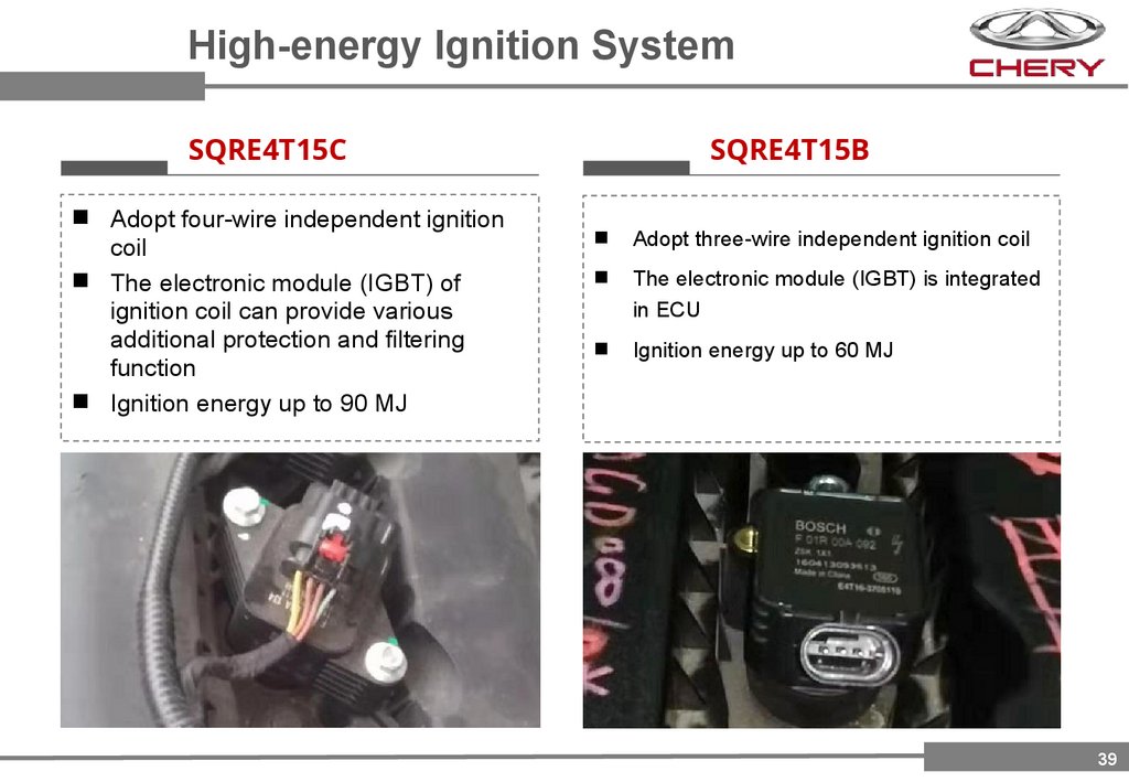
High-energy Ignition SystemSQRE4T15C
Adopt four-wire independent ignition
coil
The electronic module (IGBT) of
ignition coil can provide various
additional protection and filtering
function
Ignition energy up to 90 MJ
SQRE4T15B
Adopt three-wire independent ignition coil
The electronic module (IGBT) is integrated
in ECU
Ignition energy up to 60 MJ
39
40.
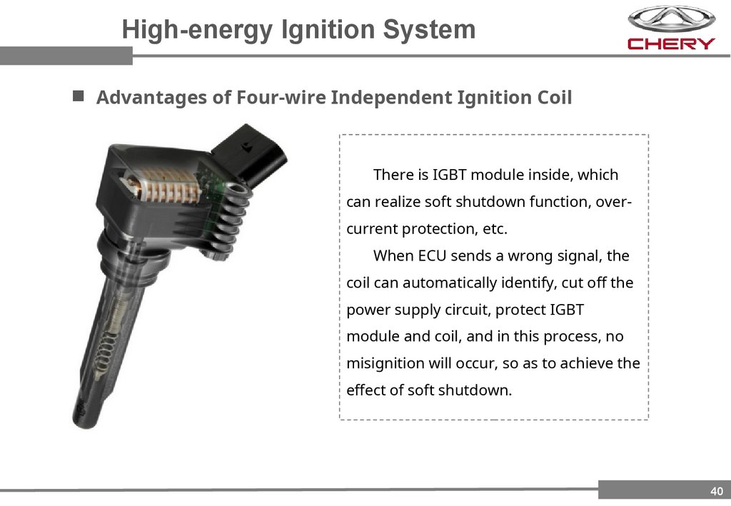
High-energy Ignition SystemAdvantages of Four-wire Independent Ignition Coil
There is IGBT module inside, which
can realize soft shutdown function, overcurrent protection, etc.
When ECU sends a wrong signal, the
coil can automatically identify, cut off the
power supply circuit, protect IGBT
module and coil, and in this process, no
misignition will occur, so as to achieve the
effect of soft shutdown.
40
41.
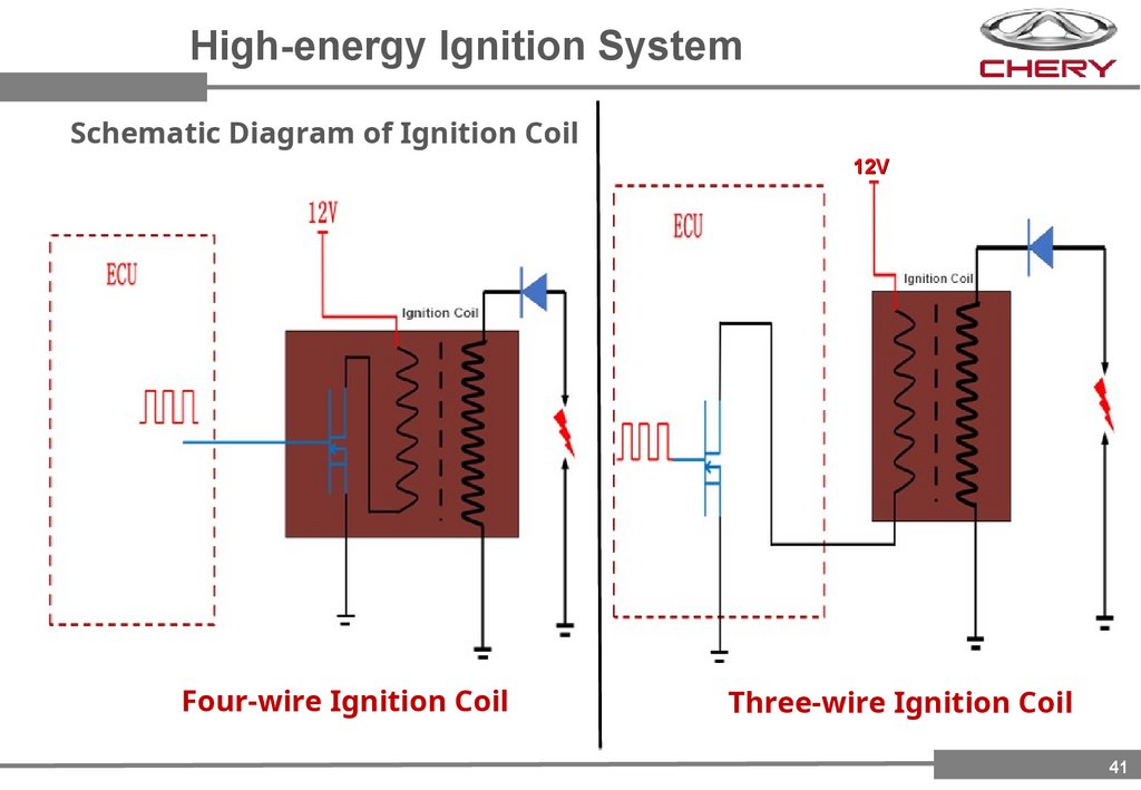
High-energy Ignition SystemSchematic Diagram of Ignition Coil
12V
Four-wire Ignition Coil
Three-wire Ignition Coil
41
42.
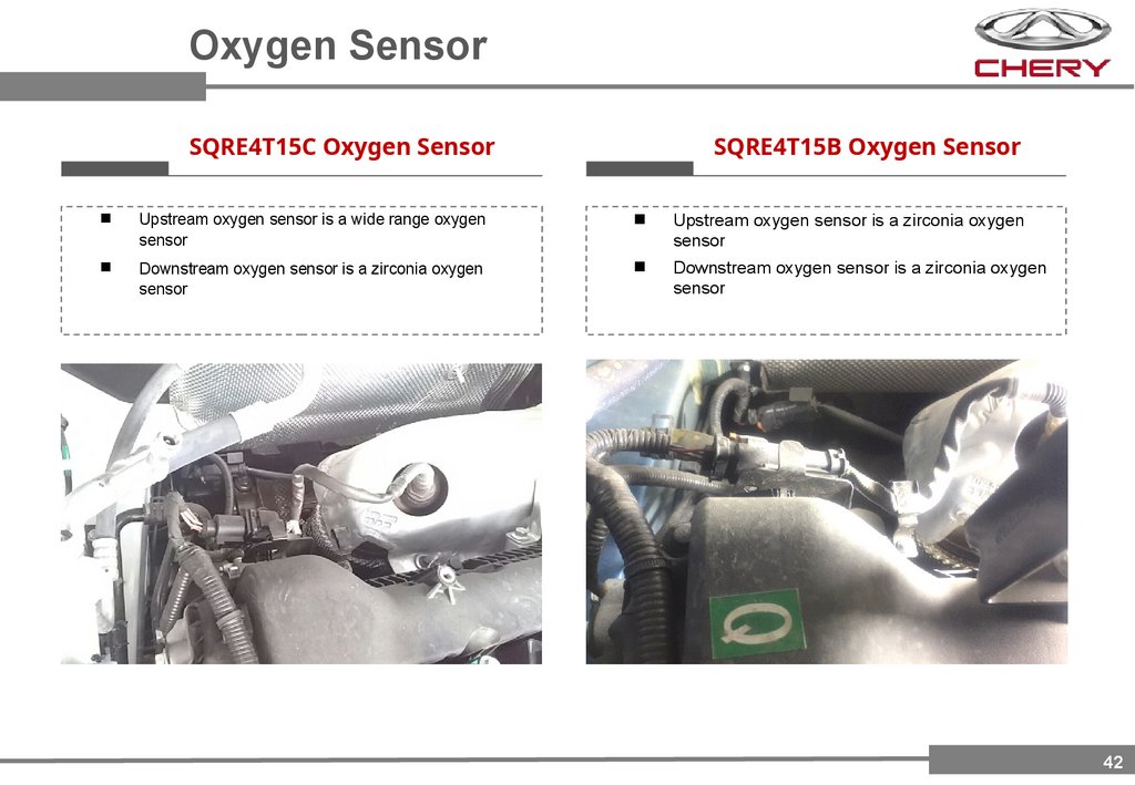
Oxygen SensorSQRE4T15C Oxygen Sensor
SQRE4T15B Oxygen Sensor
Upstream oxygen sensor is a wide range oxygen
sensor
Upstream oxygen sensor is a zirconia oxygen
sensor
Downstream oxygen sensor is a zirconia oxygen
sensor
Downstream oxygen sensor is a zirconia oxygen
sensor
42
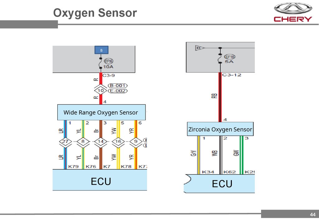
43.
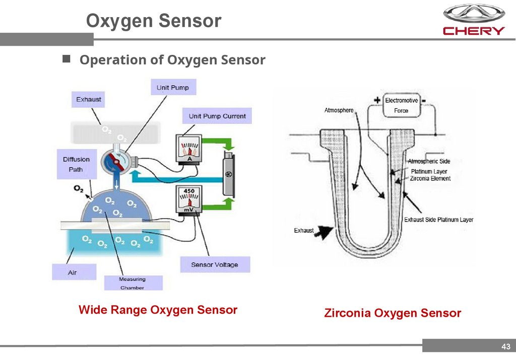
Oxygen SensorOperation of Oxygen Sensor
Wide Range Oxygen Sensor
Zirconia Oxygen Sensor
43
44.
Oxygen SensorB
Wide Range Oxygen Sensor
Zirconia Oxygen Sensor
ECU
ECU
44
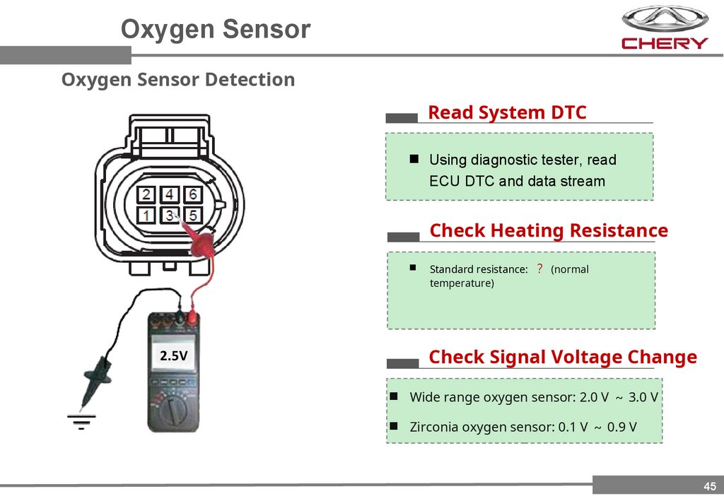
45.
Oxygen SensorOxygen Sensor Detection
Read System DTC
Using diagnostic tester, read
ECU DTC and data stream
Check Heating Resistance
2.5V
Standard resistance: (normal
temperature)
Check Signal Voltage Change
Wide range oxygen sensor: 2.0 V 3.0 V
Zirconia oxygen sensor: 0.1 V 0.9 V
45
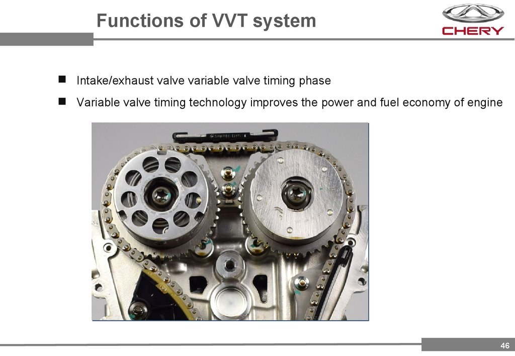
46.
Functions of VVT systemIntake/exhaust valve variable valve timing phase
Variable valve timing technology improves the power and fuel economy of engine
46
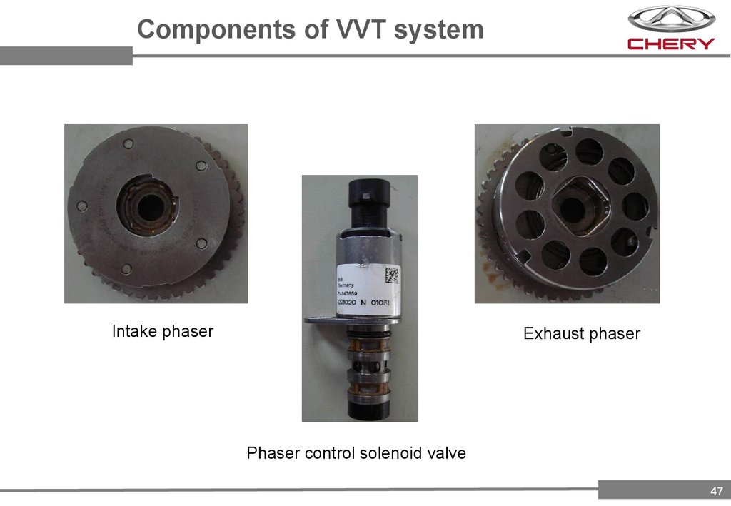
47.
Components of VVT systemIntake phaser
Exhaust phaser
Phaser control solenoid valve
47
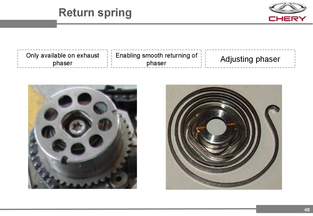
48.
Return springOnly available on exhaust
phaser
Enabling smooth returning of
phaser
Adjusting phaser
48
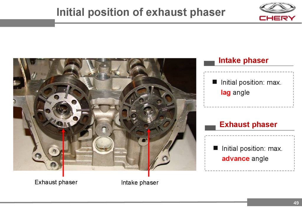
49.
Initial position of exhaust phaserIntake phaser
Initial position: max.
lag angle
Exhaust phaser
Initial position: max.
advance angle
Exhaust phaser
Intake phaser
49
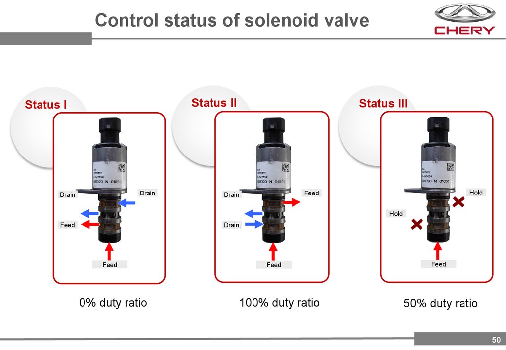
50.
Control status of solenoid valveStatus II
Status I
Drain
Drain
Status III
Hold
Feed
Drain
Hold
Feed
Drain
Feed
0% duty ratio
Feed
100% duty ratio
Feed
50% duty ratio
50
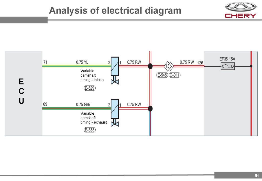
51.
Analysis of electrical diagramE
C
U
Variable
camshaft
timing - intake
Variable
camshaft
timing - exhaust
51
52.
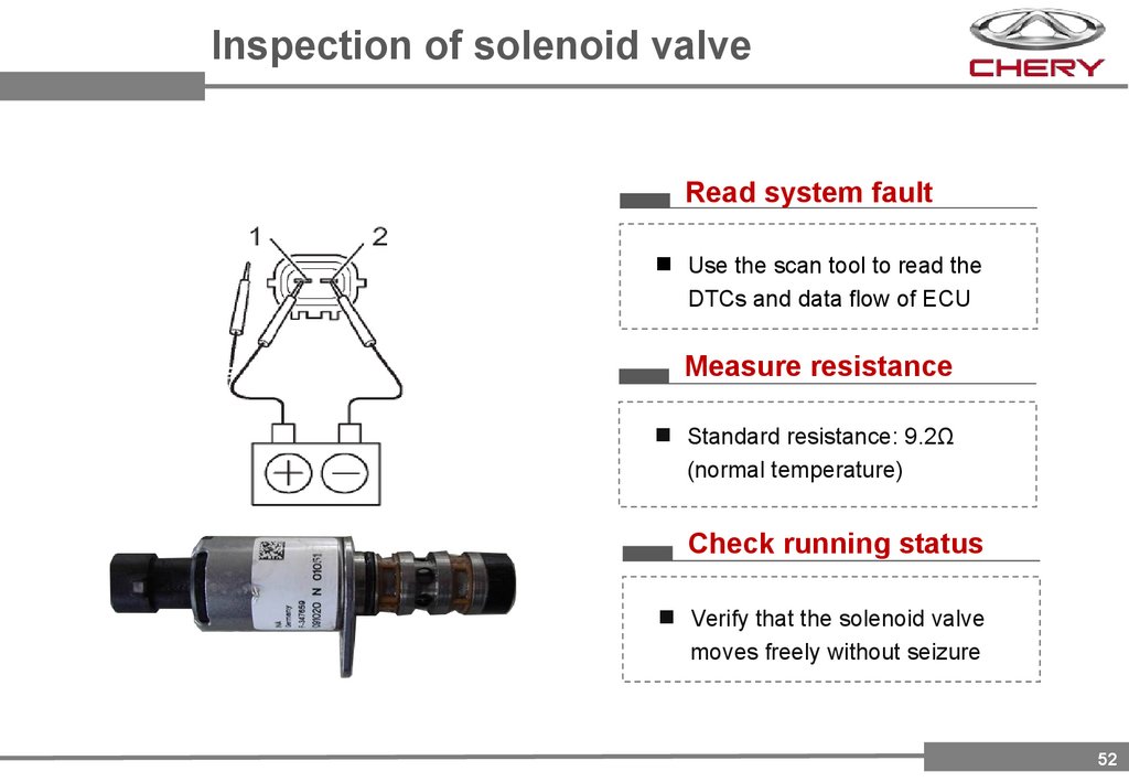
Inspection of solenoid valveRead system fault
Use the scan tool to read the
DTCs and data flow of ECU
Measure resistance
Standard resistance: 9.2Ω
(normal temperature)
Check running status
Verify that the solenoid valve
moves freely without seizure
52
53.
Part 4Euro VI B Vehicle
Emission Standards
And Malfunction
Diagnosis
53
54.
EURO VI B Standards IntroductionPositioning of EURO VI B Vehicle Emission Standards
54
55.
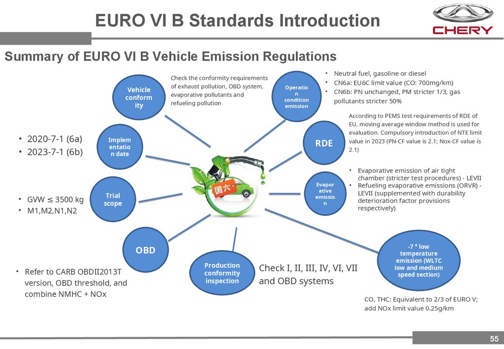
EURO VI B Standards IntroductionSummary of EURO VI B Vehicle Emission Regulations
Vehicle
conform
ity
• 2020-7-1 (6a)
• 2023-7-1 (6b)
Check the conformity requirements
of exhaust pollution, OBD system,
evaporative pollutants and
refueling pollution
Implem
entatio
n date
Operatio
n
condition
emission
• Neutral fuel, gasoline or diesel
• CN6a: EU6C limit value (CO: 700mg/km)
• CN6b: PN unchanged, PM stricter 1/3, gas
pollutants stricter 50%
RDE
According to PEMS test requirements of RDE of
EU, moving average window method is used for
evaluation. Compulsory introduction of NTE limit
value in 2023 (PN-CF value is 2.1; Nox-CF value is
2.1)
• GVW ≤ 3500 kg
• M1,M2,N1,N2
Evapor
ative
emissio
n
Trial
scope
OBD
• Refer to CARB OBDII2013T
version, OBD threshold, and
combine NMHC + NOx
Production
conformity
inspection
Check I, II, III, IV, VI, VII
and OBD systems
Evaporative emission of air tight
chamber (stricter test procedures) - LEVII
Refueling evaporative emissions (ORVR) LEVII (supplemented with durability
deterioration factor provisions
respectively)
-7 ° low
temperature
emission (WLTC
low and medium
speed section)
CO, THC: Equivalent to 2/3 of EURO V;
add NOx limit value 0.25g/km
55
56.
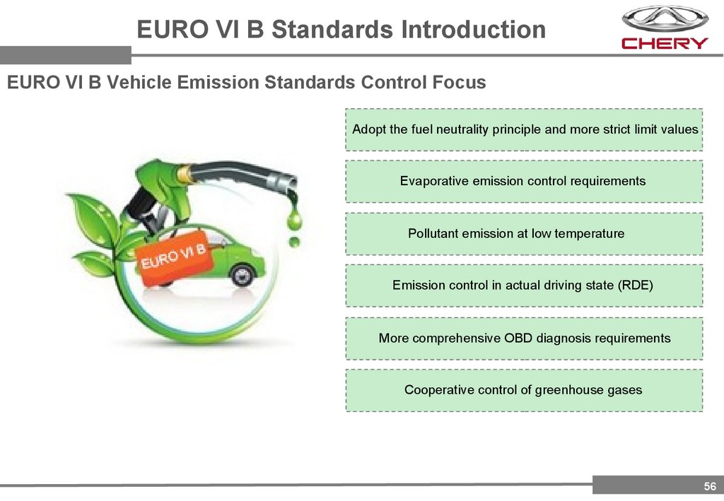
EURO VI B Standards IntroductionEURO VI B Vehicle Emission Standards Control Focus
Adopt the fuel neutrality principle and more strict limit values
Evaporative emission control requirements
Pollutant emission at low temperature
Emission control in actual driving state (RDE)
More comprehensive OBD diagnosis requirements
Cooperative control of greenhouse gases
56
57.
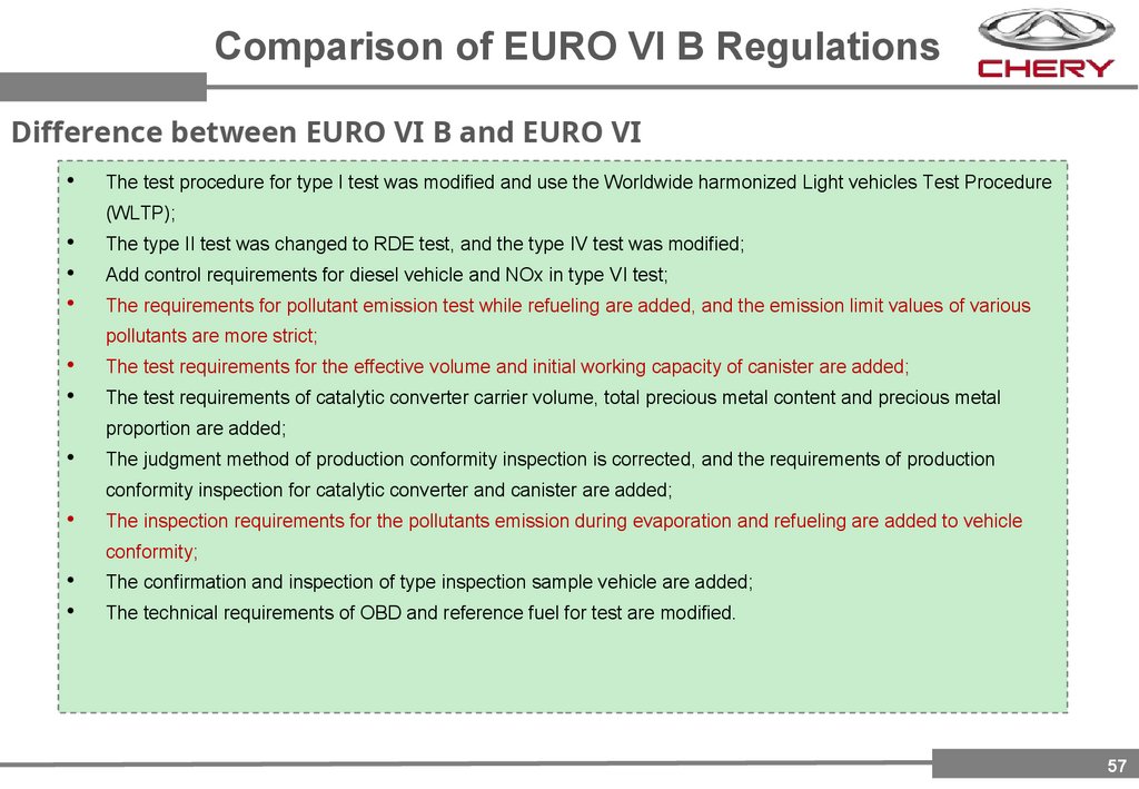
Comparison of EURO VI B RegulationsDifference between EURO VI B and EURO VI
The test procedure for type I test was modified and use the Worldwide harmonized Light vehicles Test Procedure
(WLTP);
The type II test was changed to RDE test, and the type IV test was modified;
Add control requirements for diesel vehicle and NOx in type VI test;
The requirements for pollutant emission test while refueling are added, and the emission limit values of various
pollutants are more strict;
The test requirements for the effective volume and initial working capacity of canister are added;
The test requirements of catalytic converter carrier volume, total precious metal content and precious metal
proportion are added;
The judgment method of production conformity inspection is corrected, and the requirements of production
conformity inspection for catalytic converter and canister are added;
The inspection requirements for the pollutants emission during evaporation and refueling are added to vehicle
conformity;
The confirmation and inspection of type inspection sample vehicle are added;
The technical requirements of OBD and reference fuel for test are modified.
57
58.
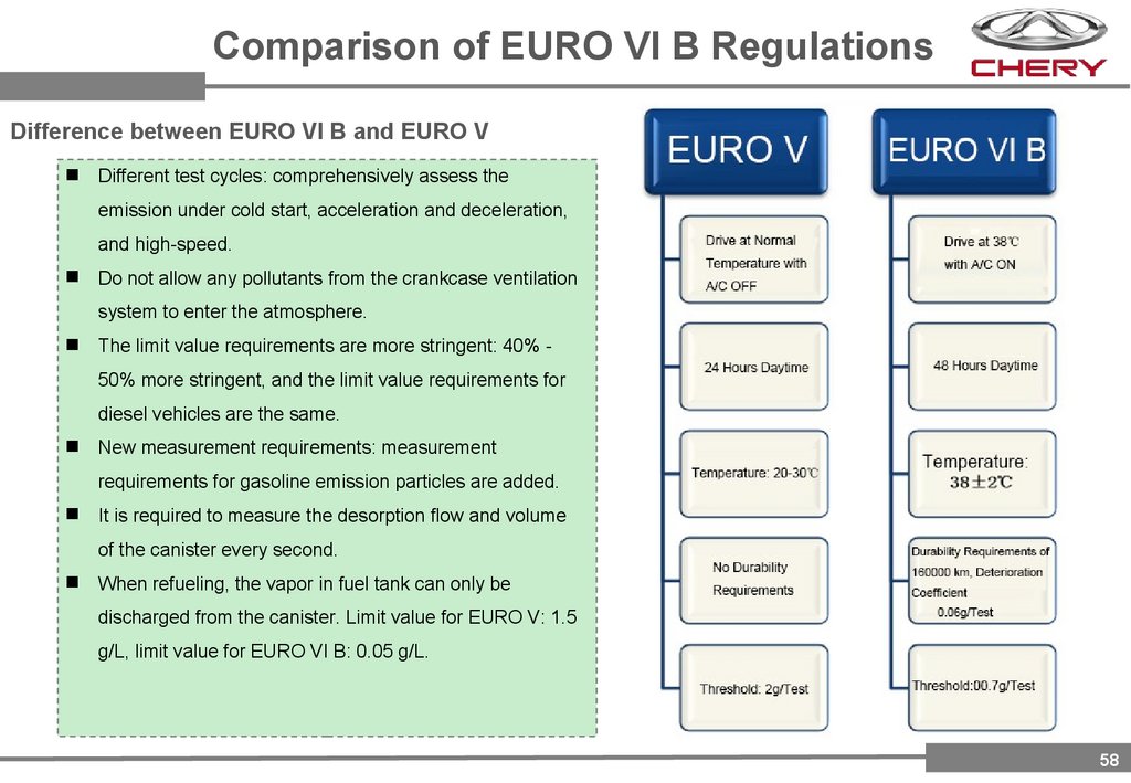
Comparison of EURO VI B RegulationsDifference between EURO VI B and EURO V
Different test cycles: comprehensively assess the
emission under cold start, acceleration and deceleration,
and high-speed.
Do not allow any pollutants from the crankcase ventilation
system to enter the atmosphere.
The limit value requirements are more stringent: 40% 50% more stringent, and the limit value requirements for
diesel vehicles are the same.
New measurement requirements: measurement
requirements for gasoline emission particles are added.
It is required to measure the desorption flow and volume
of the canister every second.
When refueling, the vapor in fuel tank can only be
discharged from the canister. Limit value for EURO V: 1.5
g/L, limit value for EURO VI B: 0.05 g/L.
58
59.
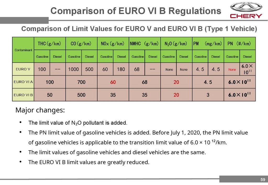
Comparison of EURO VI B RegulationsComparison of Limit Values for EURO V and EURO VI B (Type 1 Vehicle)
Major changes:
The limit value of N₂O pollutant is added.
The PN limit value of gasoline vehicles is added. Before July 1, 2020, the PN limit value
of gasoline vehicles is applicable to the transition limit value of 6.0 × 10 ¹²/km.
The limit values of gasoline vehicles and diesel vehicles are the same.
The EURO VI B limit values are greatly reduced.
59
60.
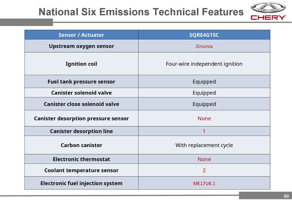
National Six Emissions Technical FeaturesSensor / Actuator
SQRE4G15C
Upstream oxygen sensor
Zirconia
Ignition coil
Four-wire independent ignition
Fuel tank pressure sensor
Equipped
Canister solenoid valve
Equipped
Canister close solenoid valve
Equipped
Canister desorption pressure sensor
None
Canister desorption line
1
Carbon canister
With replacement cycle
Electronic thermostat
None
Coolant temperature sensor
2
Electronic fuel injection system
ME17U6.1
60
61.
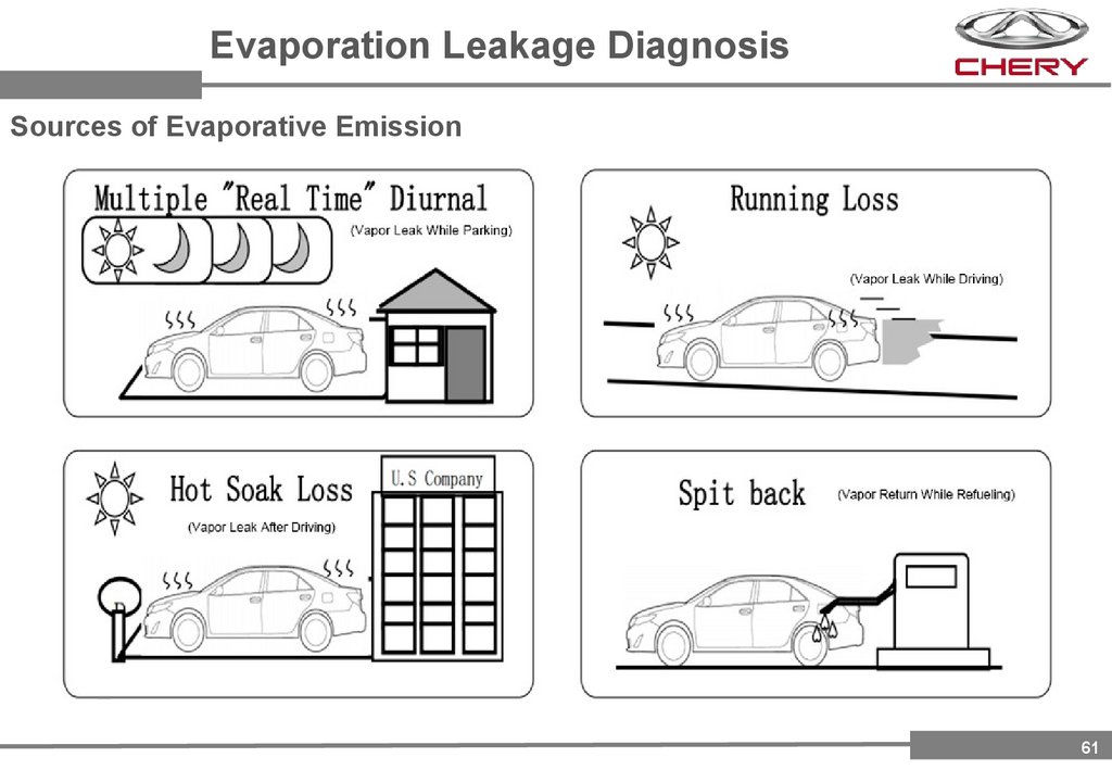
Evaporation Leakage DiagnosisSources of Evaporative Emission
61
62.
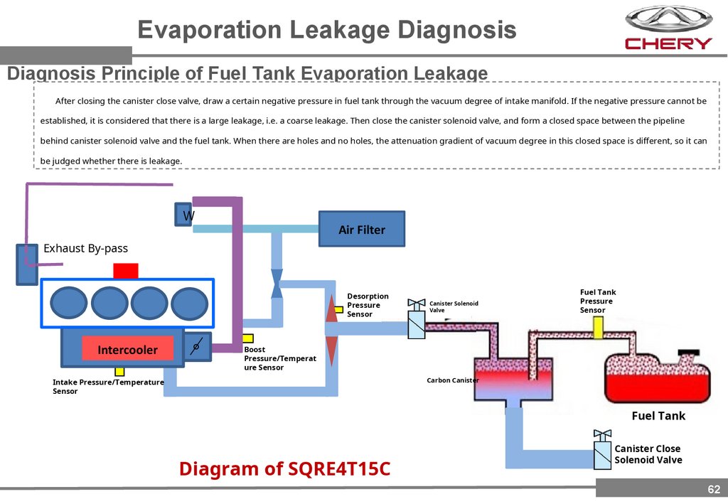
Evaporation Leakage DiagnosisDiagnosis Principle of Fuel Tank Evaporation Leakage
After closing the canister close valve, draw a certain negative pressure in fuel tank through the vacuum degree of intake manifold. If the negative pressure cannot be
established, it is considered that there is a large leakage, i.e. a coarse leakage. Then close the canister solenoid valve, and form a closed space between the pipeline
behind canister solenoid valve and the fuel tank. When there are holes and no holes, the attenuation gradient of vacuum degree in this closed space is different, so it can
be judged whether there is leakage.
Air Filter
Exhaust By-pass
Desorption
Pressure
Sensor
Intercooler
。
Canister Solenoid
Valve
Fuel Tank
Pressure
Sensor
Boost
Pressure/Temperat
ure Sensor
Carbon Canister
Intake Pressure/Temperature
Sensor
Fuel Tank
Diagram of SQRE4T15C
Canister Close
Solenoid Valve
62
63.
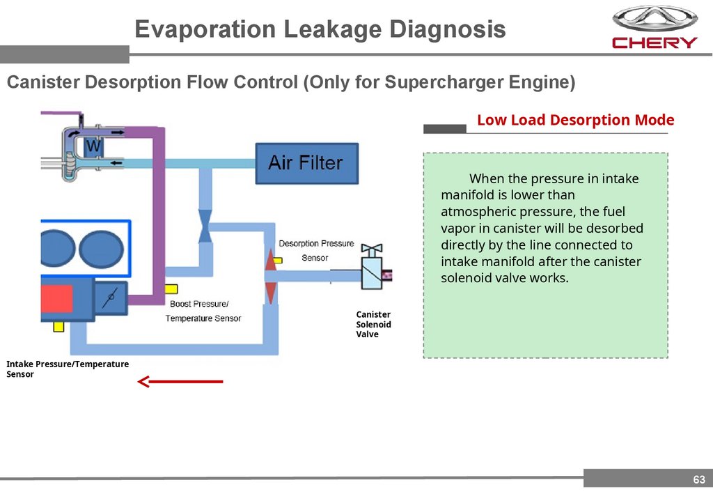
Evaporation Leakage DiagnosisCanister Desorption Flow Control (Only for Supercharger Engine)
Low Load Desorption Mode
When the pressure in intake
manifold is lower than
atmospheric pressure, the fuel
vapor in canister will be desorbed
directly by the line connected to
intake manifold after the canister
solenoid valve works.
Canister
Solenoid
Valve
Intake Pressure/Temperature
Sensor
63
64.
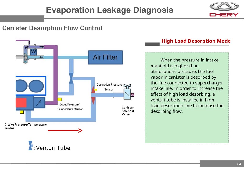
Evaporation Leakage DiagnosisCanister Desorption Flow Control
High Load Desorption Mode
Canister
Solenoid
Valve
When the pressure in intake
manifold is higher than
atmospheric pressure, the fuel
vapor in canister is desorbed by
the line connected to supercharger
intake line. In order to increase the
effect of high load desorbing, a
venturi tube is installed in high
load desorption line to increase the
desorbing flow.
Intake Pressure/Temperature
Sensor
: Venturi Tube
64
65.
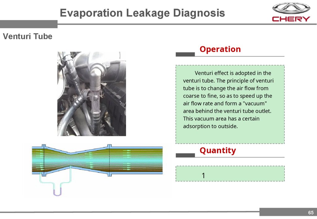
Evaporation Leakage DiagnosisVenturi Tube
Operation
Venturi effect is adopted in the
venturi tube. The principle of venturi
tube is to change the air flow from
coarse to fine, so as to speed up the
air flow rate and form a "vacuum"
area behind the venturi tube outlet.
This vacuum area has a certain
adsorption to outside.
Quantity
1
65
66.
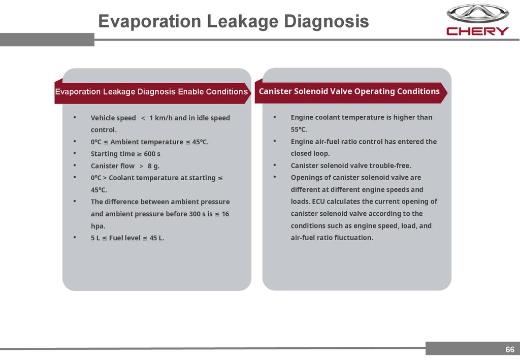
Evaporation Leakage DiagnosisEvaporation Leakage Diagnosis Enable Conditions
Vehicle speed 1 km/h and in idle speed
Canister Solenoid Valve Operating Conditions
Engine coolant temperature is higher than
55℃.
control.
0℃ ≤ Ambient temperature ≤ 45℃.
Starting time ≥ 600 s
Canister flow 8 g.
Canister solenoid valve trouble-free.
0℃ > Coolant temperature at starting ≤
Openings of canister solenoid valve are
Engine air-fuel ratio control has entered the
closed loop.
45℃.
different at different engine speeds and
The difference between ambient pressure
loads. ECU calculates the current opening of
and ambient pressure before 300 s is ≤ 16
canister solenoid valve according to the
hpa.
conditions such as engine speed, load, and
5 L ≤ Fuel level ≤ 45 L.
air-fuel ratio fluctuation.
66
67.
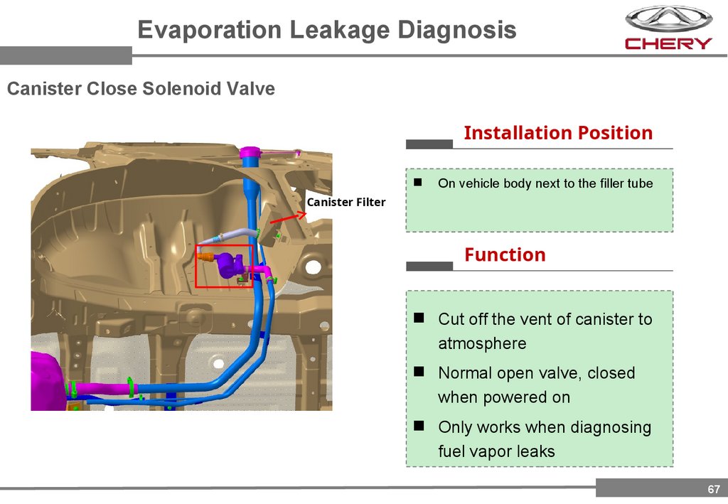
Evaporation Leakage DiagnosisCanister Close Solenoid Valve
Installation Position
On vehicle body next to the filler tube
Canister Filter
Function
Cut off the vent of canister to
atmosphere
Normal open valve, closed
when powered on
Only works when diagnosing
fuel vapor leaks
67
68.
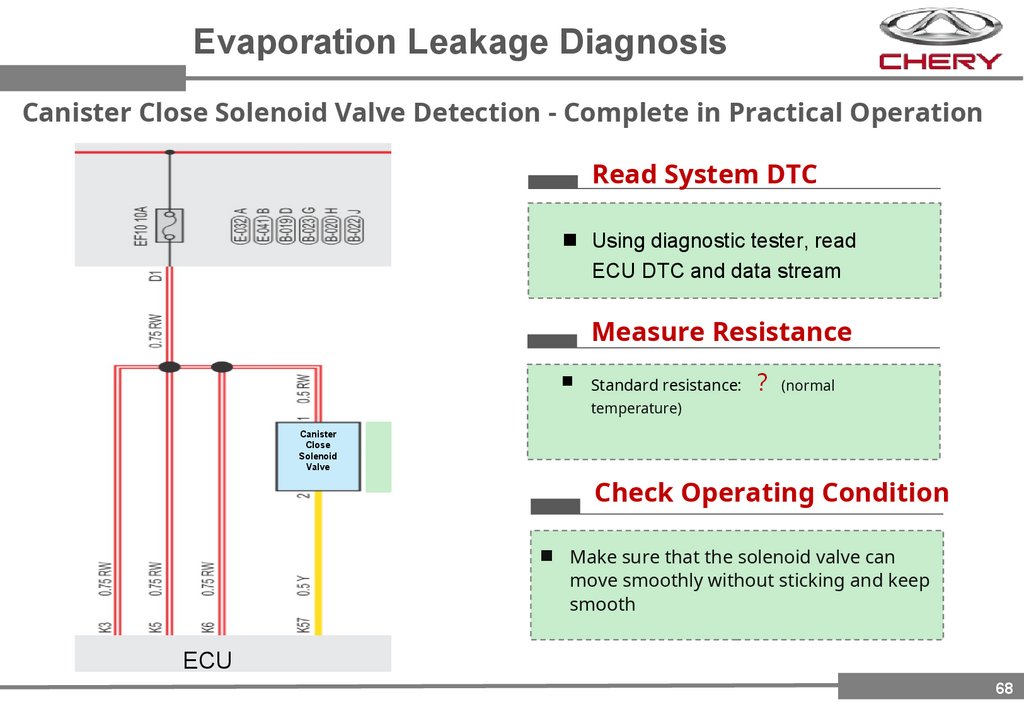
Evaporation Leakage DiagnosisCanister Close Solenoid Valve Detection - Complete in Practical Operation
Read System DTC
Using diagnostic tester, read
ECU DTC and data stream
Measure Resistance
Standard resistance: (normal
temperature)
Canister
Close
Solenoid
Valve
Check Operating Condition
Make sure that the solenoid valve can
move smoothly without sticking and keep
smooth
ECU
68
69.
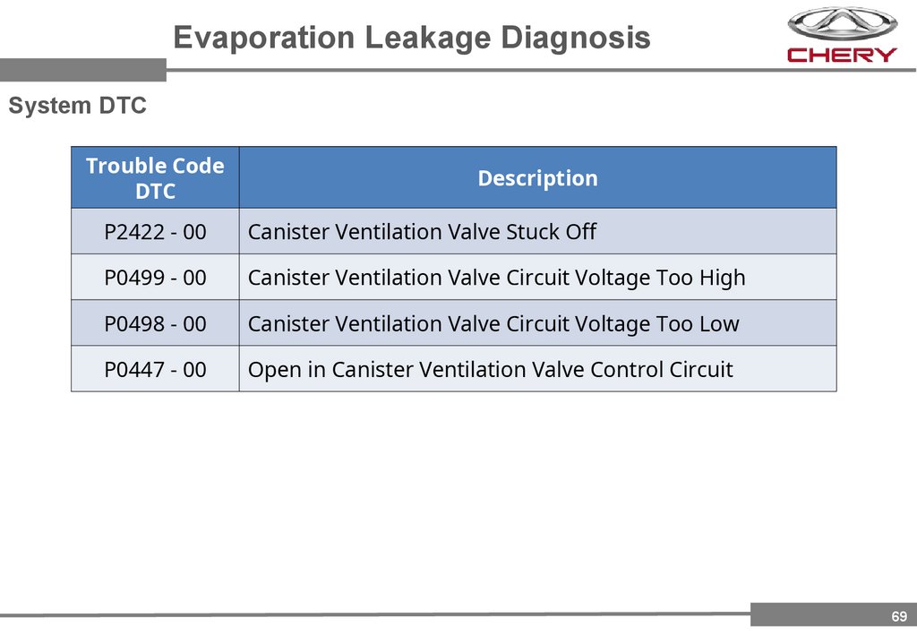
Evaporation Leakage DiagnosisSystem DTC
Trouble Code
DTC
Description
P2422 - 00
Canister Ventilation Valve Stuck Off
P0499 - 00
Canister Ventilation Valve Circuit Voltage Too High
P0498 - 00
Canister Ventilation Valve Circuit Voltage Too Low
P0447 - 00
Open in Canister Ventilation Valve Control Circuit
69
70.
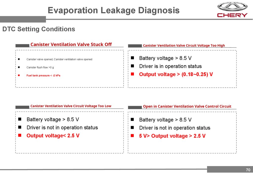
Evaporation Leakage DiagnosisDTC Setting Conditions
Canister Ventilation Valve Stuck Off
Canister Ventilation Valve Circuit Voltage Too High
Canister valve opened; Canister ventilation valve opened
Battery voltage > 8.5 V
Canister flush flow >0 g
Driver is in operation status
Fuel tank pressure < -2 kPa
Output voltage > (0.18~0.25) V
Canister Ventilation Valve Circuit Voltage Too Low
Open in Canister Ventilation Valve Control Circuit
Battery voltage > 8.5 V
Battery voltage > 8.5 V
Driver is not in operation status
Driver is not in operation status
Output voltage< 2.5 V
5 V> Output voltage > 2.5 V
70
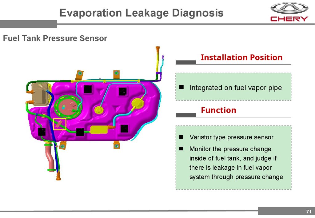
71.
Evaporation Leakage DiagnosisFuel Tank Pressure Sensor
Installation Position
Integrated on fuel vapor pipe
Function
Varistor type pressure sensor
Monitor the pressure change
inside of fuel tank, and judge if
there is leakage in fuel vapor
system through pressure change
71
72.
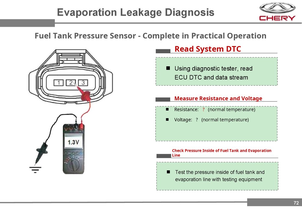
Evaporation Leakage DiagnosisFuel Tank Pressure Sensor - Complete in Practical Operation
Read System DTC
Using diagnostic tester, read
ECU DTC and data stream
Measure Resistance and Voltage
Resistance: (normal temperature)
Voltage: (normal temperature)
Check Pressure Inside of Fuel Tank and Evaporation
Line
Test the pressure inside of fuel tank and
evaporation line with testing equipment
72
73.
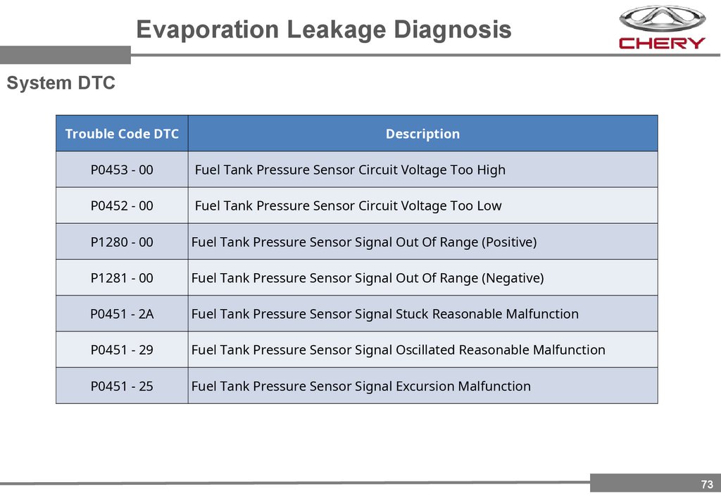
Evaporation Leakage DiagnosisSystem DTC
Trouble Code DTC
Description
P0453 - 00
Fuel Tank Pressure Sensor Circuit Voltage Too High
P0452 - 00
Fuel Tank Pressure Sensor Circuit Voltage Too Low
P1280 - 00
Fuel Tank Pressure Sensor Signal Out Of Range (Positive)
P1281 - 00
Fuel Tank Pressure Sensor Signal Out Of Range (Negative)
P0451 - 2A
Fuel Tank Pressure Sensor Signal Stuck Reasonable Malfunction
P0451 - 29
Fuel Tank Pressure Sensor Signal Oscillated Reasonable Malfunction
P0451 - 25
Fuel Tank Pressure Sensor Signal Excursion Malfunction
73
74.
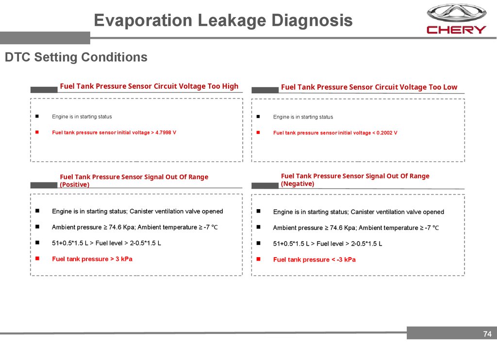
Evaporation Leakage DiagnosisDTC Setting Conditions
Fuel Tank Pressure Sensor Circuit Voltage Too High
Fuel Tank Pressure Sensor Circuit Voltage Too Low
Engine is in starting status
Engine is in starting status
Fuel tank pressure sensor initial voltage > 4.7998 V
Fuel tank pressure sensor initial voltage < 0.2002 V
Fuel Tank Pressure Sensor Signal Out Of Range
(Negative)
Fuel Tank Pressure Sensor Signal Out Of Range
(Positive)
Engine is in starting status; Canister ventilation valve opened
Engine is in starting status; Canister ventilation valve opened
Ambient pressure ≥ 74.6 Kpa; Ambient temperature ≥ -7 ℃
Ambient pressure ≥ 74.6 Kpa; Ambient temperature ≥ -7 ℃
51+0.5*1.5 L > Fuel level > 2-0.5*1.5 L
51+0.5*1.5 L > Fuel level > 2-0.5*1.5 L
Fuel tank pressure > 3 kPa
Fuel tank pressure < -3 kPa
74
75.
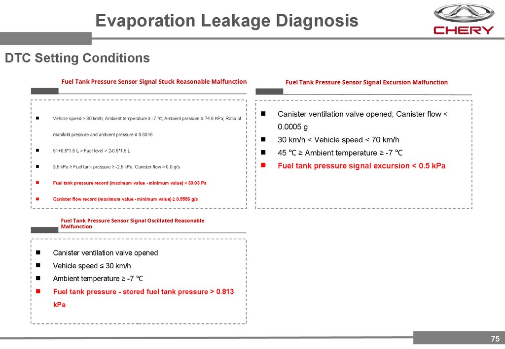
Evaporation Leakage DiagnosisDTC Setting Conditions
Fuel Tank Pressure Sensor Signal Stuck Reasonable Malfunction
Vehicle speed > 30 km/h; Ambient temperature ≥ -7 ℃; Ambient pressure ≥ 74.6 KPa; Ratio of
Fuel Tank Pressure Sensor Signal Excursion Malfunction
Canister ventilation valve opened; Canister flow <
0.0005 g
manifold pressure and ambient pressure ≤ 0.6016
30 km/h < Vehicle speed < 70 km/h
51+0.5*1.5 L > Fuel level > 2-0.5*1.5 L
45 ℃ ≥ Ambient temperature ≥ -7 ℃
3.5 kPa ≥ Fuel tank pressure ≥ -2.5 kPa; Canister flow > 0.0 g/s
Fuel tank pressure signal excursion < 0.5 kPa
Fuel tank pressure record (maximum value - minimum value) < 30.03 Pa
Canister flow record (maximum value - minimum value) ≥ 0.5556 g/s
Fuel Tank Pressure Sensor Signal Oscillated Reasonable
Malfunction
Canister ventilation valve opened
Vehicle speed ≤ 30 km/h
Ambient temperature ≥ -7 ℃
Fuel tank pressure - stored fuel tank pressure > 0.813
kPa
75
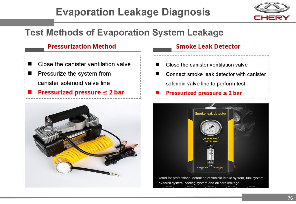
76.
Evaporation Leakage DiagnosisTest Methods of Evaporation System Leakage
Smoke Leak Detector
Pressurization Method
Close the canister ventilation valve
Close the canister ventilation valve
Pressurize the system from
Connect smoke leak detector with canister
canister solenoid valve line
Pressurized pressure ≤ 2 bar
solenoid valve line to perform test
Pressurized pressure ≤ 2 bar
76
77.
Part 5Engine
Immobilizer
77
78.
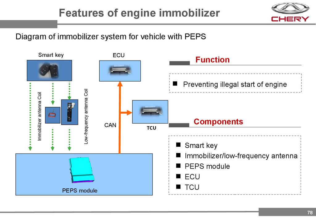
Features of engine immobilizerDiagram of immobilizer system for vehicle with PEPS
Smart key
ECU
Function
Low-frequency antenna Coil
Immobilizer antenna Coil
Preventing illegal start of engine
PEPS module
CAN
TCU
Components
Smart key
Immobilizer/low-frequency antenna
PEPS module
ECU
TCU
78
79.
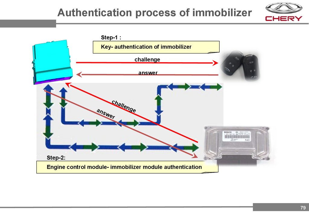
Authentication process of immobilizerStep-1 :
Key- authentication of immobilizer
challenge
answer
ans
cha
we
llen
ge
r
Step-2:
Engine control module- immobilizer module authentication
79
80.
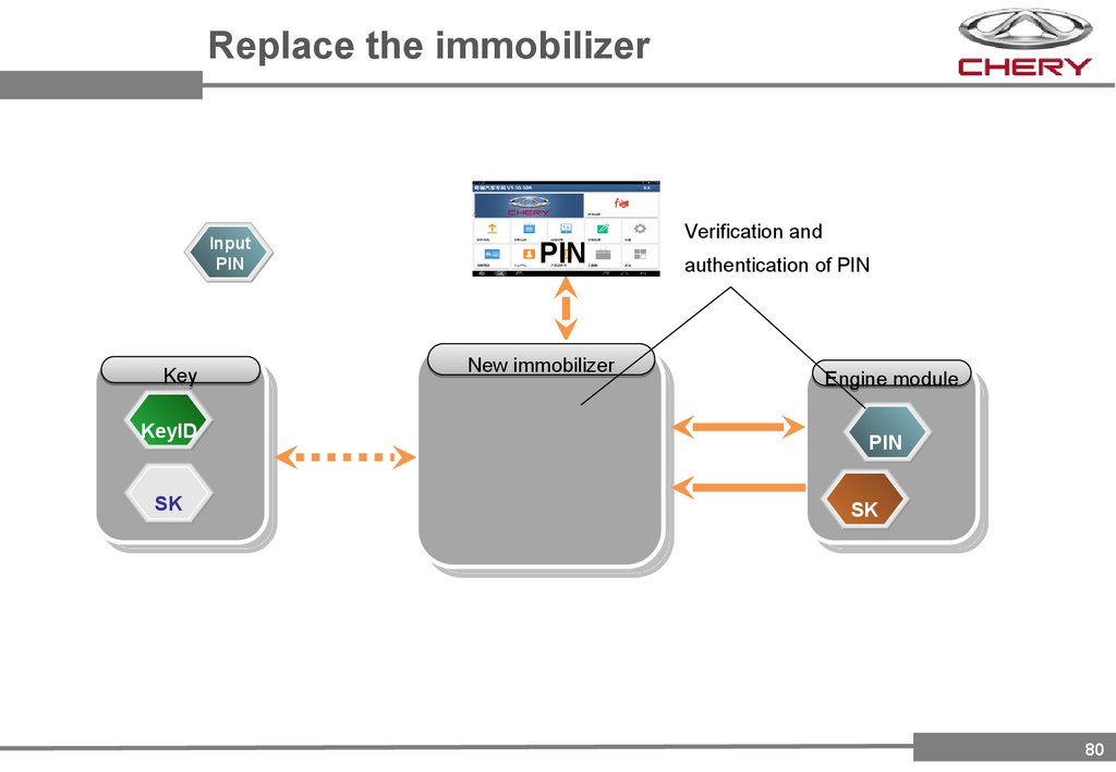
Replace the immobilizerInput
PIN
Key
KeyID
KeyID
SK
PIN
PIN
PIN
PIN
New immobilizer
Verification and
authentication of PIN
Engine module
PIN
SK
SK
80
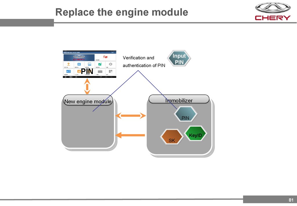
81.
Replace the engine moduleVerification and
PINPIN
New engine module
authentication of PIN
Input
PIN
Immobilizer
PIN
SK
KeyID
81
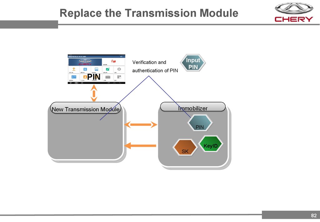
82.
Replace the Transmission ModuleVerification and
PINPIN
New Transmission Module
authentication of PIN
Input
PIN
Immobilizer
PIN
SK
KeyID
82
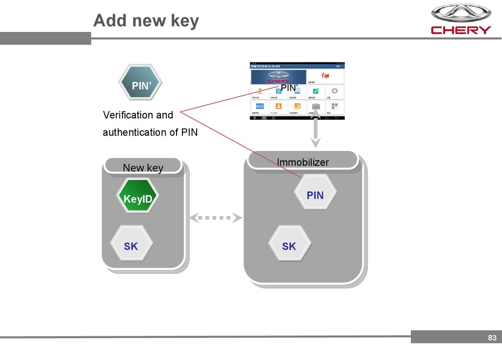
83.
Add new keyPIN’
PIN’
PIN
Verification and
authentication of PIN
New
Newkey
key
Immobilizer
Immobilizer
PIN
PIN
KeyID
KeyID
SK
SK
SK
83
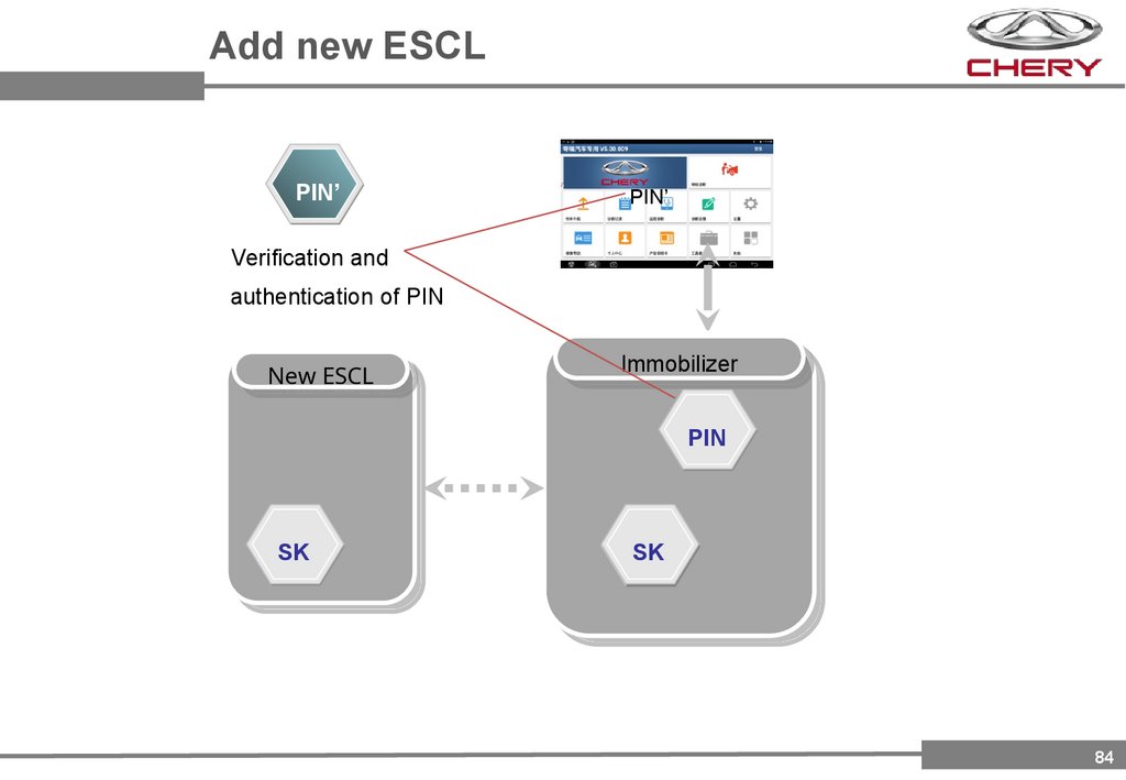
84.
Add new ESCLPIN’
PIN’
PIN
Verification and
authentication of PIN
New
NewESCL
ESCL
Immobilizer
Immobilizer
PIN
PIN
SK
SK
SK
84
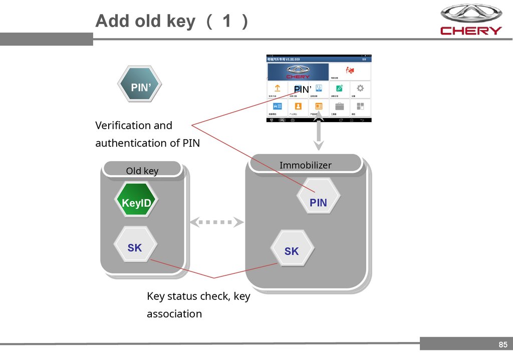
85.
Add old key 1PIN’
PIN’
PIN
Verification and
authentication of PIN
Old
Oldkey
key
Immobilizer
Immobilizer
PIN
KeyID
KeyID
SK
SK
SK
Key status check, key
association
85
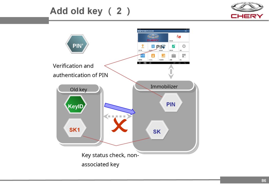
86.
Add old key 2PIN’
PIN’
PIN
Verification and
authentication of PIN
Immobilizer
Immobilizer
Old
Oldkey
key
PIN
PIN
KeyID
SK1
SK
SK
Key status check, nonassociated key
86
87.
Thanks!87