


 Механика
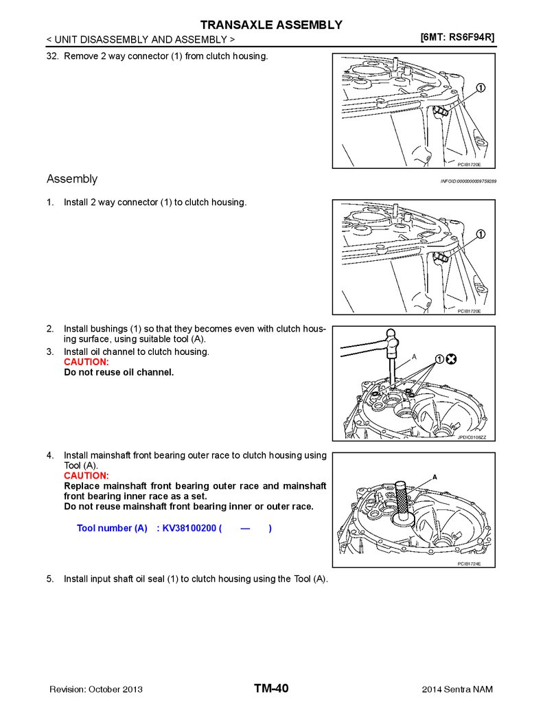
Похожие презентации:


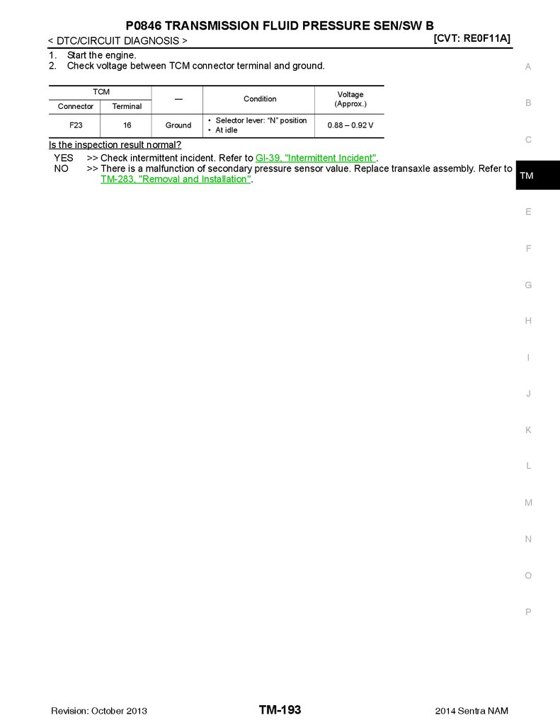
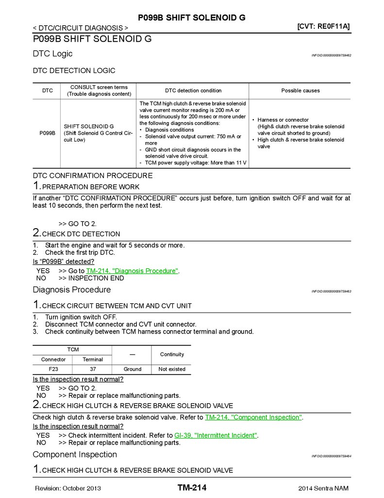
 - Technical Highlights")
Transmission & Driveline Section. TM Transaxle & Transmission
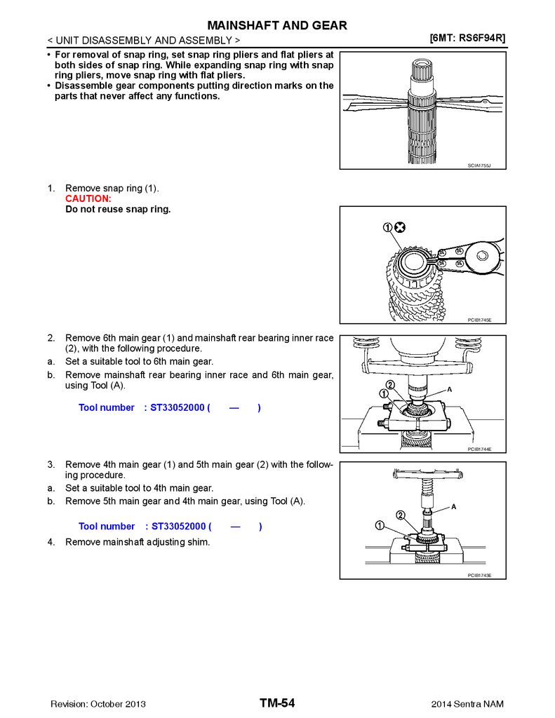
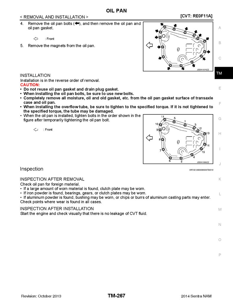
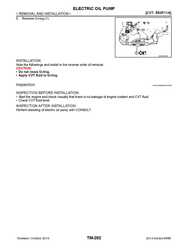
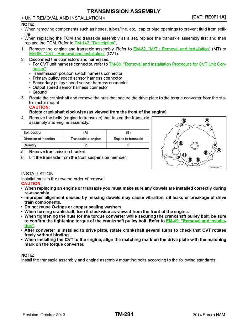
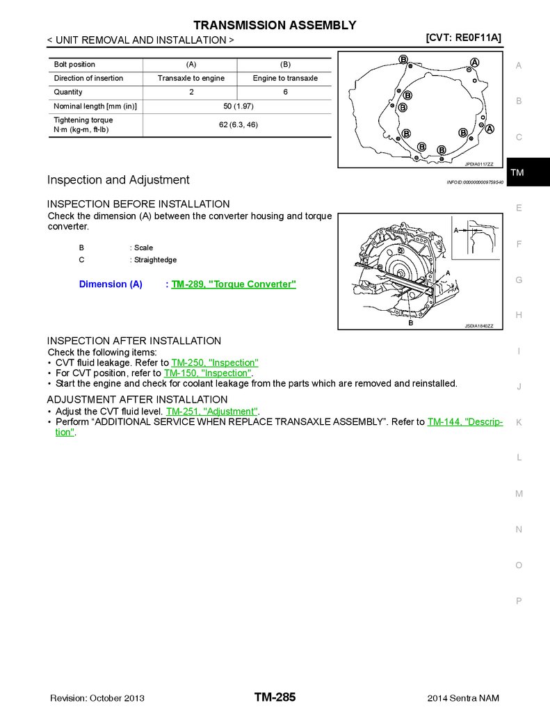
1.
TRANSMISSION & DRIVELINESECTION
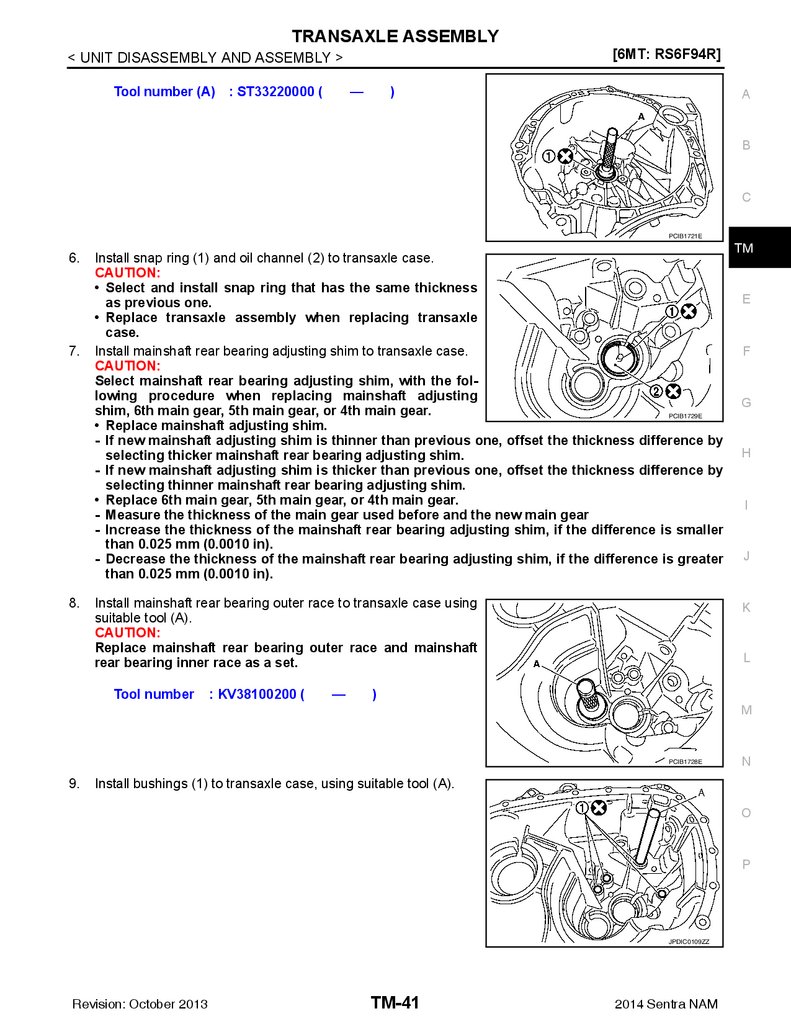
TM
TRANSAXLE & TRANSMISSION
A
B
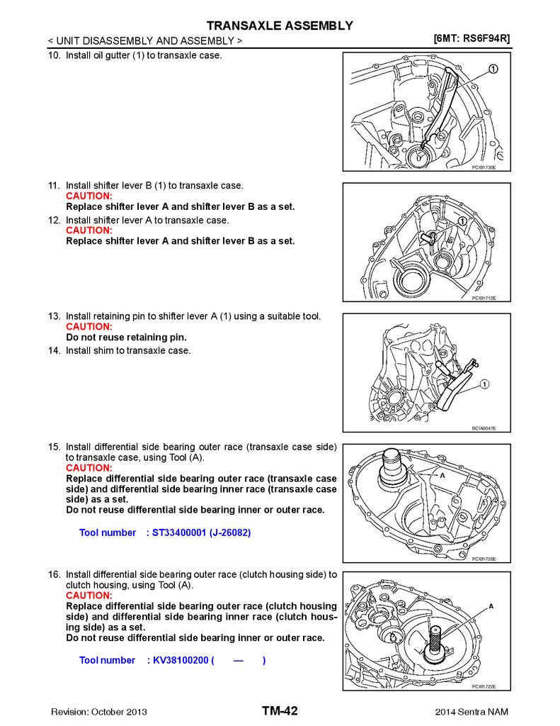
C
TM
E
CONTENTS
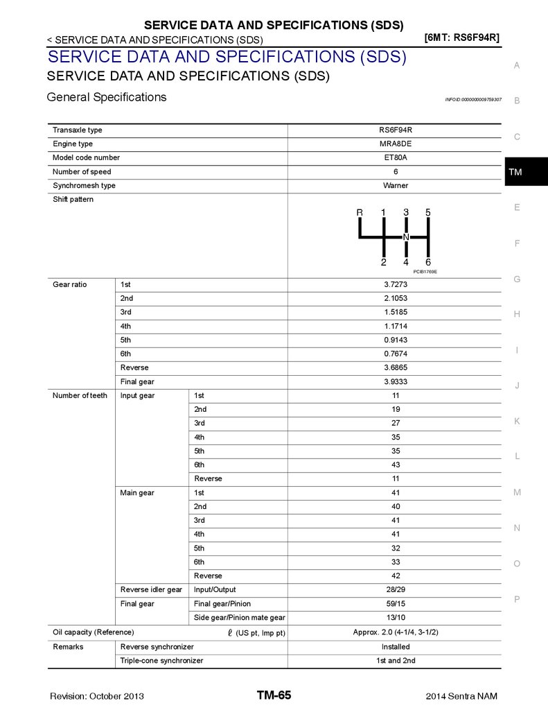
6MT: RS6F94R
PRECAUTION ............................................... 7
PRECAUTIONS ................................................... 7
Precaution for Supplemental Restraint System
(SRS) "AIR BAG" and "SEAT BELT PRE-TENSIONER" ................................................................... 7
Precaution for Procedure without Cowl Top Cover...... 7
Service Notice or Precautions for Manual Transaxle .......................................................................... 7
Liquid Gasket ............................................................ 8
PREPARATION ............................................ 9
NOISE, VIBRATION AND HARSHNESS
(NVH) TROUBLESHOOTING ........................... 18
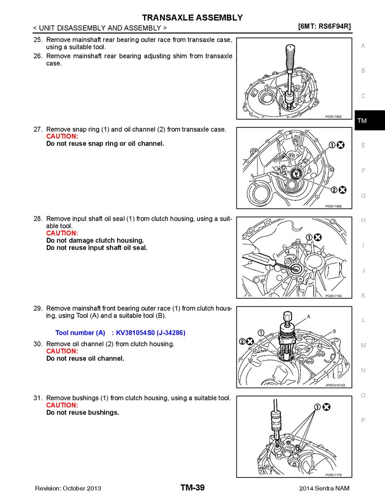
F
NVH Troubleshooting Chart ....................................18
PERIODIC MAINTENANCE ........................ 19
M/T OIL .............................................................. 19
Inspection ................................................................19
Draining ...................................................................19
Refilling ....................................................................19
REMOVAL AND INSTALLATION ............... 20
SIDE OIL SEAL ................................................. 20
PREPARATION ................................................... 9
Removal and Installation .........................................20
Inspection ................................................................20
Special Service Tools ................................................ 9
Commercial Service Tools ...................................... 11
POSITION SWITCH .......................................... 21
G
H
I
J
K
SYSTEM DESCRIPTION ............................. 14
Removal and Installation .........................................21
Inspection ................................................................21
COMPONENT PARTS .......................................14
CONTROL LINKAGE ........................................ 22
L
Component Parts Location ...................................... 14
Exploded View .........................................................22
Removal and Installation .........................................22
Inspection ................................................................26
M
STRUCTURE AND OPERATION .......................15
Sectional View ......................................................... 15
System Description ................................................. 15
AIR BREATHER HOSE .................................... 27
DTC/CIRCUIT DIAGNOSIS ......................... 17
Exploded View .........................................................27
Removal and Installation .........................................27
POSITION SWITCH ............................................17
UNIT REMOVAL AND INSTALLATION ...... 28
BACK-UP LAMP SWITCH ........................................ 17
BACK-UP LAMP SWITCH : Component Inspection .......................................................................... 17
TRANSAXLE ASSEMBLY ................................ 28
PARK/NEUTRAL POSITION (PNP) SWITCH ........... 17
PARK/NEUTRAL POSITION (PNP) SWITCH :
Component Inspection ............................................ 17
SYMPTOM DIAGNOSIS .............................. 18
Revision: October 2013
Exploded View .........................................................28
Removal and Installation .........................................28
Inspection ................................................................29
UNIT DISASSEMBLY AND ASSEMBLY ... 30
TRANSAXLE ASSEMBLY ................................ 30
TM-1
Exploded View .........................................................30
Disassembly ............................................................35
Assembly .................................................................40
2014 Sentra NAM
N
O
P
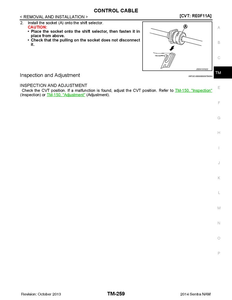
2.
Inspection ............................................................... 45COMPONENT PARTS ....................................... 73
INPUT SHAFT AND GEAR ............................... 47
CVT CONTROL SYSTEM ......................................... 73
CVT CONTROL SYSTEM : Component Parts Location ...................................................................... 73
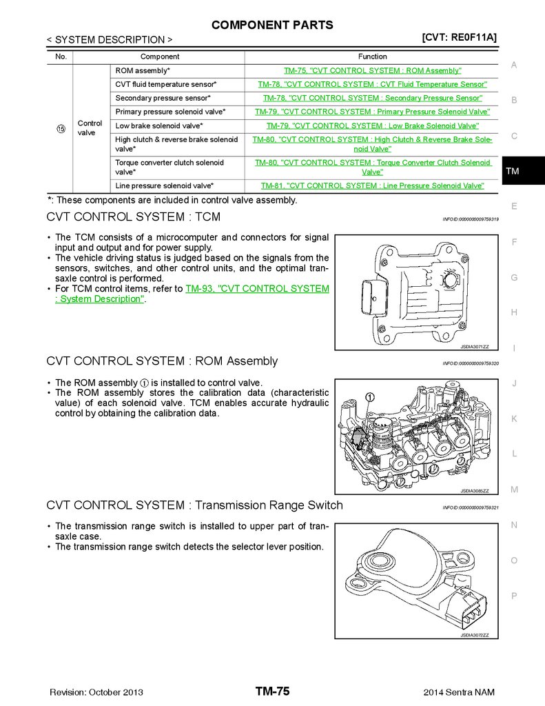
CVT CONTROL SYSTEM : TCM ............................ 75
CVT CONTROL SYSTEM : ROM Assembly .......... 75
CVT CONTROL SYSTEM : Transmission Range
Switch ..................................................................... 75
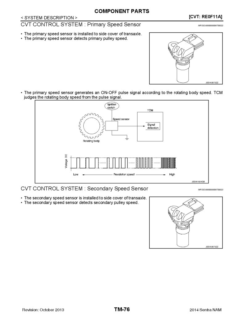
CVT CONTROL SYSTEM : Primary Speed Sensor ........................................................................... 76
CVT CONTROL SYSTEM : Secondary Speed
Sensor ..................................................................... 76
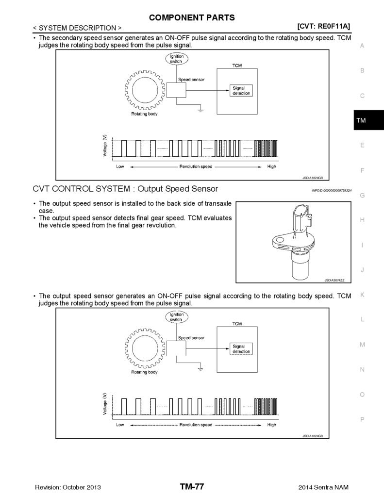
CVT CONTROL SYSTEM : Output Speed Sensor... 77
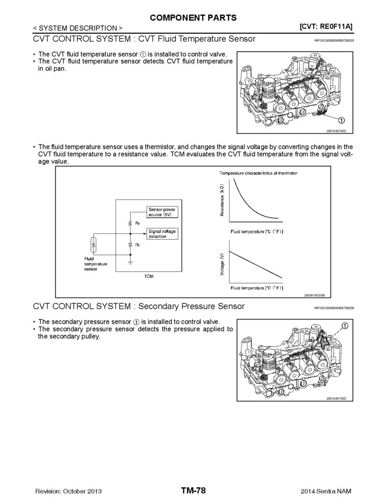
CVT CONTROL SYSTEM : CVT Fluid Temperature Sensor ............................................................. 78
CVT CONTROL SYSTEM : Secondary Pressure
Sensor ..................................................................... 78
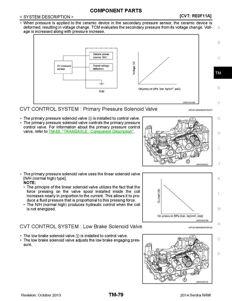
CVT CONTROL SYSTEM : Primary Pressure Solenoid Valve ............................................................ 79
CVT CONTROL SYSTEM : Low Brake Solenoid
Valve ....................................................................... 79
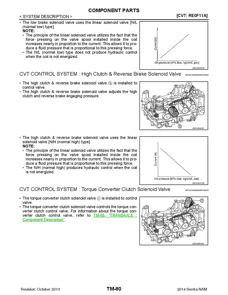
CVT CONTROL SYSTEM : High Clutch & Reverse Brake Solenoid Valve .................................... 80
CVT CONTROL SYSTEM : Torque Converter
Clutch Solenoid Valve ............................................. 80
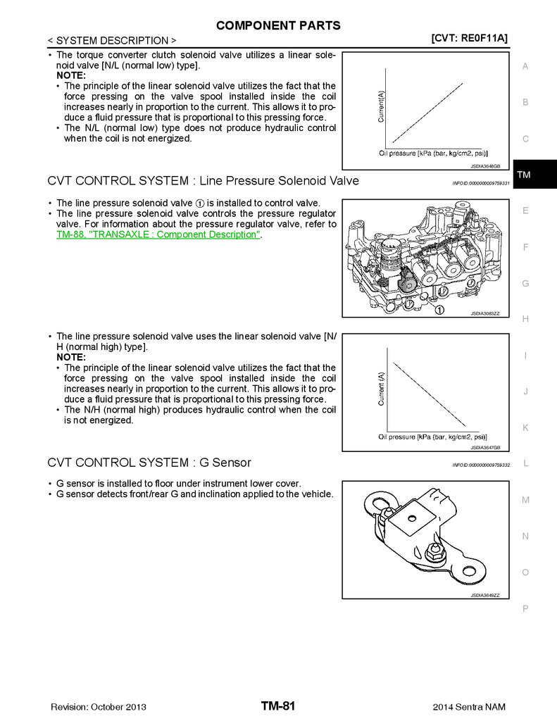
CVT CONTROL SYSTEM : Line Pressure Solenoid Valve ............................................................... 81
CVT CONTROL SYSTEM : G Sensor .................... 81
CVT CONTROL SYSTEM : Overdrive Control
Switch ..................................................................... 82
CVT CONTROL SYSTEM : OD OFF Indicator
Lamp ....................................................................... 82
CVT CONTROL SYSTEM : Shift Position Indicator ............................................................................ 83
Exploded View ........................................................ 47
Disassembly ........................................................... 47
Assembly ................................................................ 49
Inspection ............................................................... 51
MAINSHAFT AND GEAR .................................. 53
Exploded View ........................................................ 53
Disassembly ........................................................... 53
Assembly ................................................................ 55
Inspection ............................................................... 58
REVERSE IDLER SHAFT AND GEAR ............. 59
Exploded View ........................................................ 59
Disassembly ........................................................... 59
Assembly ................................................................ 60
Inspection ............................................................... 60
FINAL DRIVE ..................................................... 62
Exploded View ........................................................ 62
Disassembly ........................................................... 62
Assembly ................................................................ 63
Inspection ............................................................... 63
SERVICE DATA AND SPECIFICATIONS
(SDS) ........................................................... 65
SERVICE DATA AND SPECIFICATIONS
(SDS) .................................................................. 65
General Specifications ............................................ 65
CVT: RE0F11A
PRECAUTION ............................................. 66
PRECAUTIONS ................................................. 66
Precaution for Supplemental Restraint System
(SRS) "AIR BAG" and "SEAT BELT PRE-TENSIONER" ................................................................. 66
Precaution for Procedure without Cowl Top Cover... 66
Liquid Gasket .......................................................... 66
Precaution for TCM and Transaxle Assembly Replacement ............................................................... 67
Precaution for G Sensor Removal/Installation or
Replacement .......................................................... 67
General Precautions ............................................... 68
On Board Diagnosis (OBD) System of CVT and
Engine .................................................................... 68
Removal and Installation Procedure for CVT Unit
Connector ............................................................... 69
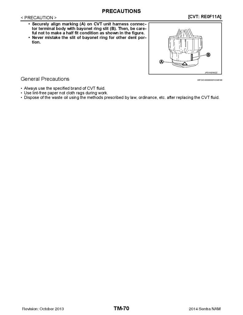
General Precautions ............................................... 70
SHIFT LOCK SYSTEM .............................................. 83
SHIFT LOCK SYSTEM : Component Parts Location .......................................................................... 83
PREPARATION ........................................... 71
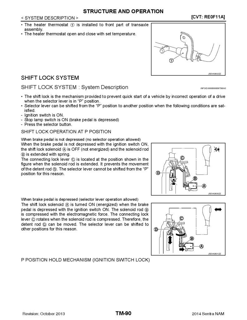
SHIFT LOCK SYSTEM .............................................. 90
SHIFT LOCK SYSTEM : System Description ......... 90
PREPARATION ................................................. 71
STRUCTURE AND OPERATION ...................... 85
TRANSAXLE ............................................................. 85
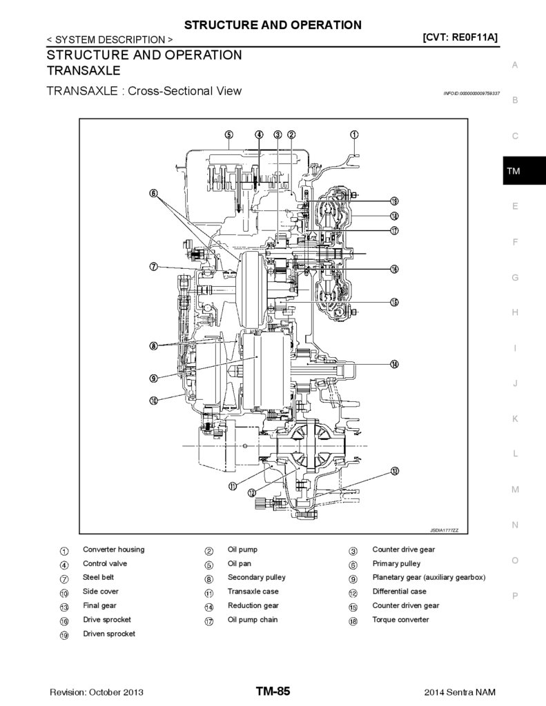
TRANSAXLE : Cross-Sectional View ..................... 85
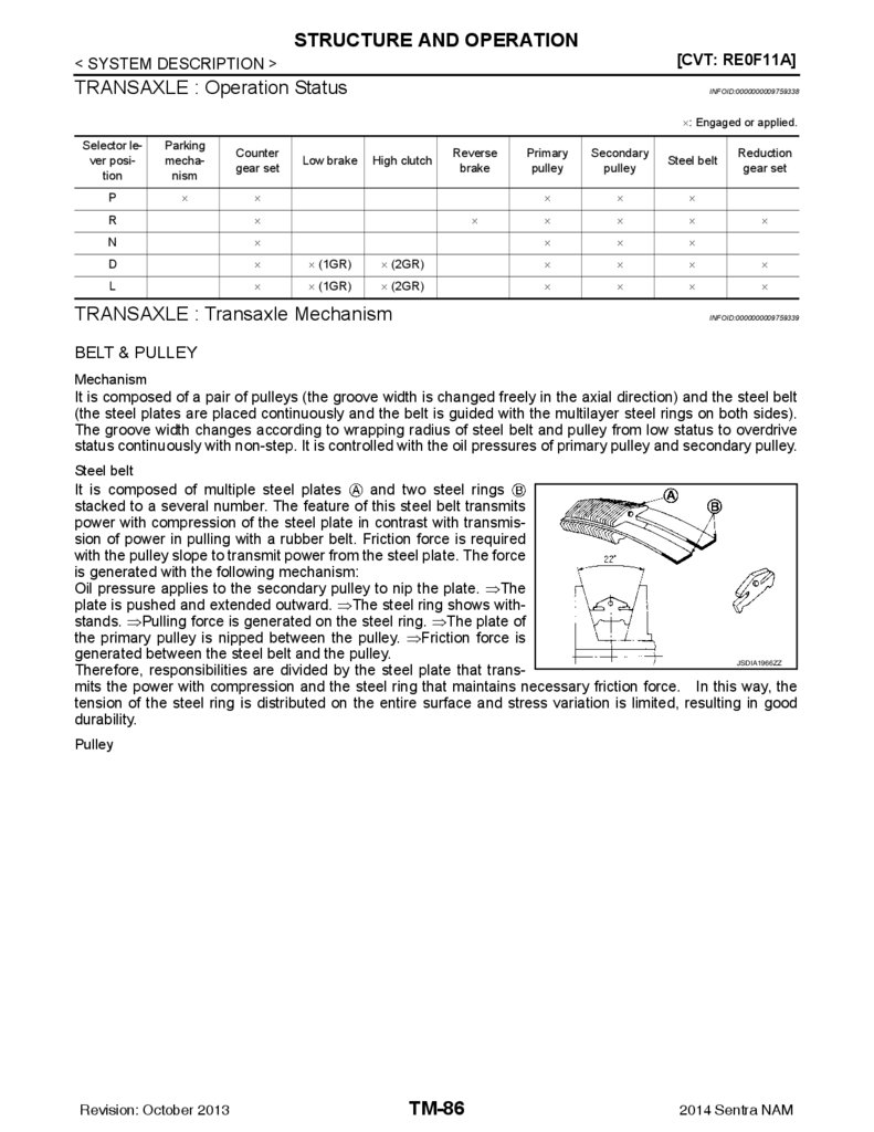
TRANSAXLE : Operation Status ............................. 86
TRANSAXLE : Transaxle Mechanism .................... 86
TRANSAXLE : Oil Pressure System ....................... 88
TRANSAXLE : Component Description .................. 88
FLUID COOLER & FLUID WARMER SYSTEM ........ 89
FLUID COOLER & FLUID WARMER SYSTEM :
System Description ................................................. 89
Special Service Tools ............................................. 71
Commercial Service Tools ...................................... 71
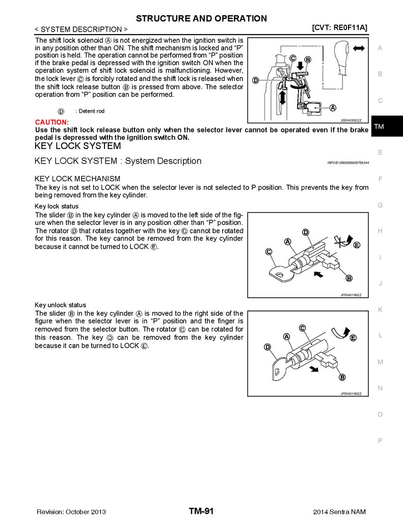
KEY LOCK SYSTEM ................................................. 91
KEY LOCK SYSTEM : System Description ............ 91
SYSTEM DESCRIPTION ............................ 73
SYSTEM ............................................................ 92
Revision: October 2013
TM-2
2014 Sentra NAM
3.
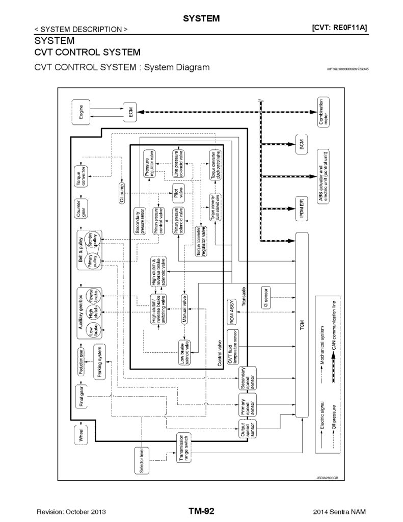
CVT CONTROL SYSTEM ......................................... 92CVT CONTROL SYSTEM : System Diagram ......... 92
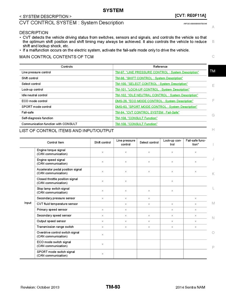
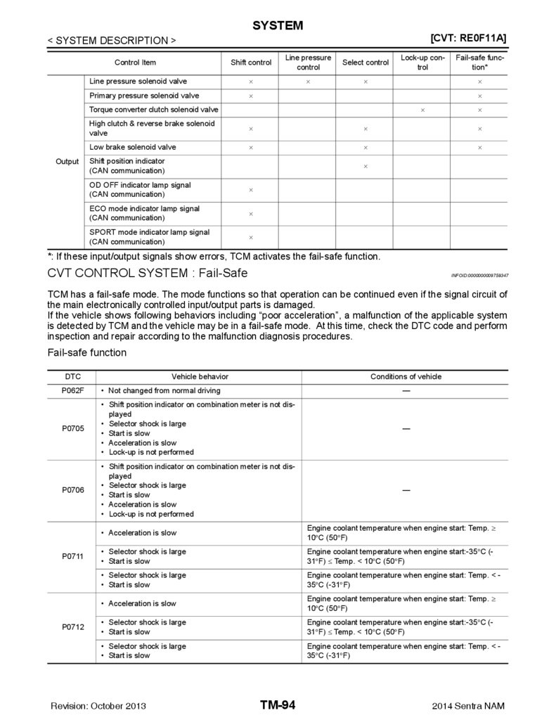
CVT CONTROL SYSTEM : System Description .... 93
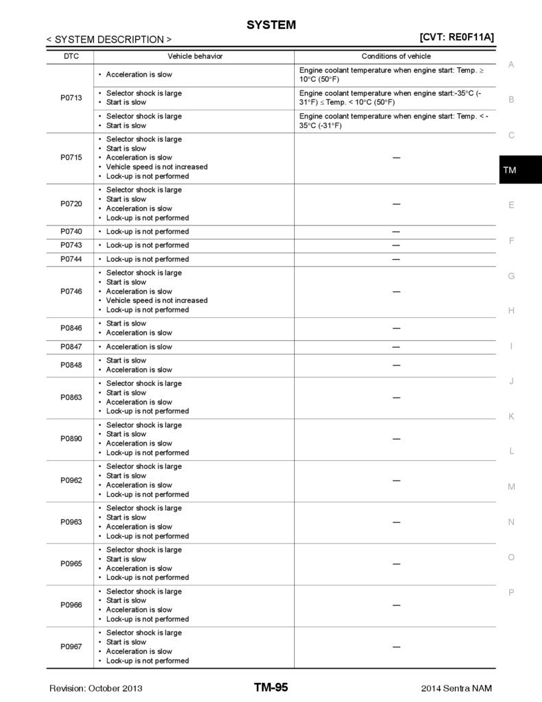
CVT CONTROL SYSTEM : Fail-Safe ..................... 94
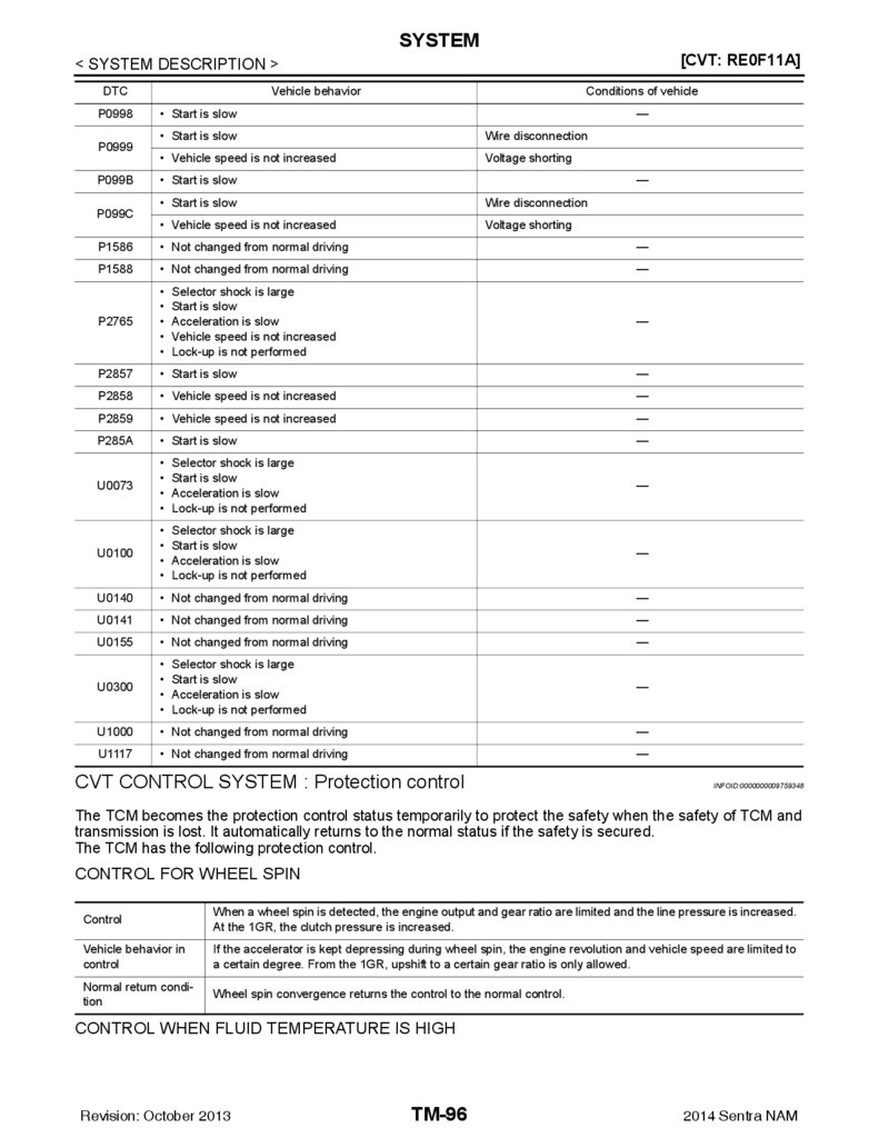
CVT CONTROL SYSTEM : Protection control ........ 96
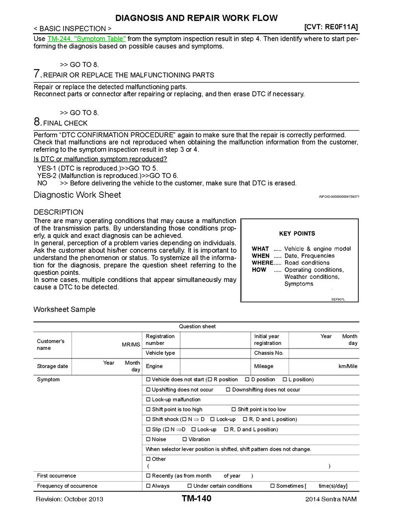
DIAGNOSIS AND REPAIR WORK FLOW ..... 139
LINE PRESSURE CONTROL ................................... 97
LINE PRESSURE CONTROL : System Description .......................................................................... 97
Description ............................................................. 142
Work Procedure ..................................................... 142
SHIFT CONTROL ...................................................... 98
SHIFT CONTROL : System Description ................. 98
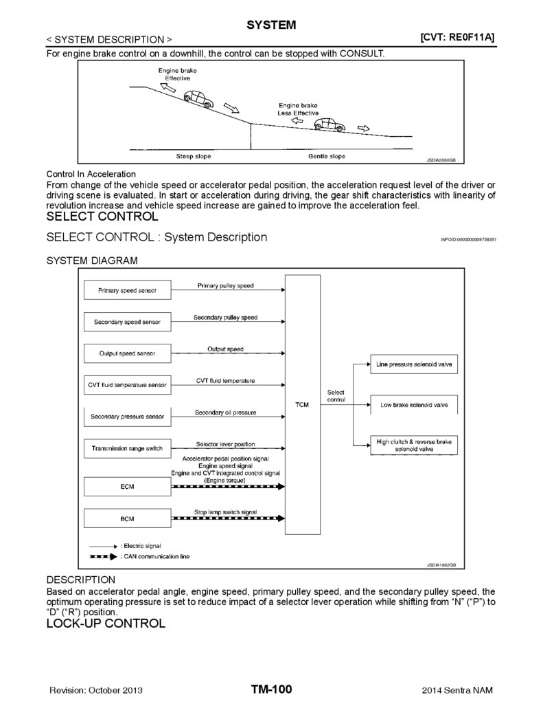
SELECT CONTROL ................................................ 100
SELECT CONTROL : System Description ............ 100
Work Flow .............................................................. 139
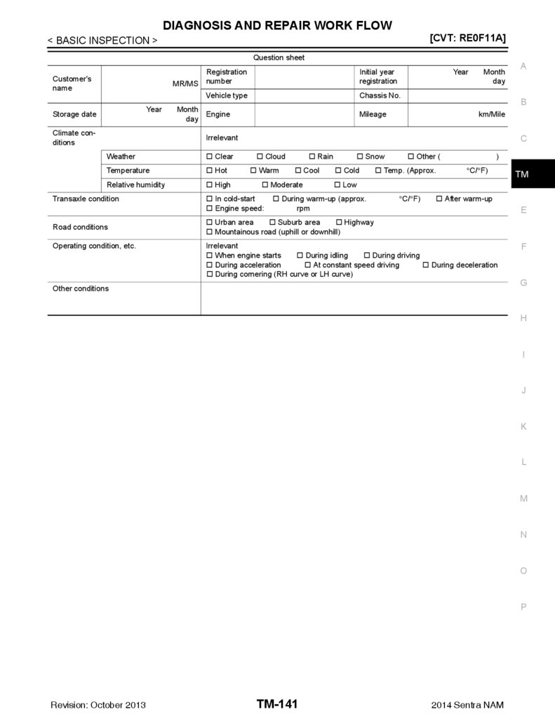
Diagnostic Work Sheet .......................................... 140
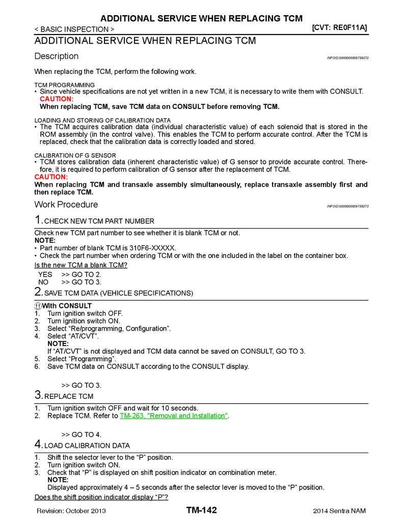
ADDITIONAL SERVICE WHEN REPLACING
TCM ................................................................. 142
ADDITIONAL SERVICE WHEN REPLACING
TRANSAXLE ASSEMBLY .............................. 144
Description ............................................................. 144
Work Procedure ..................................................... 144
CALIBRATION OF G SENSOR ...................... 147
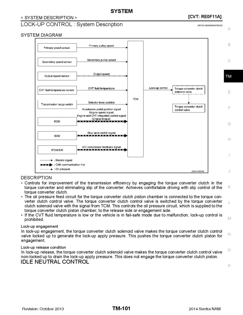
LOCK-UP CONTROL .............................................. 100
LOCK-UP CONTROL : System Description .......... 101
Description ............................................................. 147
Work Procedure ..................................................... 147
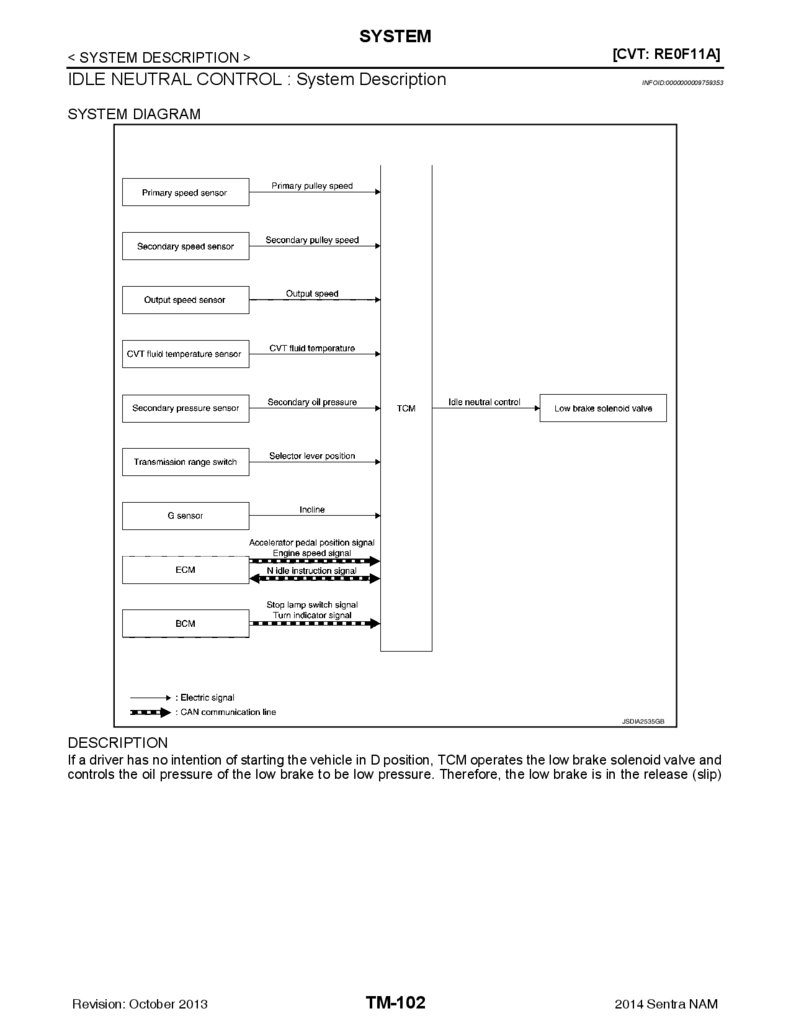
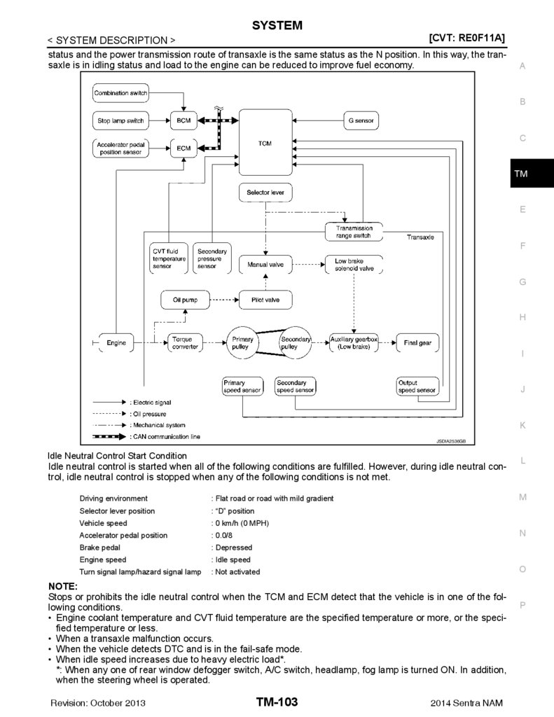
IDLE NEUTRAL CONTROL .................................... 101
IDLE NEUTRAL CONTROL : System Description.. 102
STALL TEST ................................................... 148
ECO MODE CONTROL ........................................... 104
ECO MODE CONTROL : System Description ...... 104
LINE PRESSURE TEST .................................. 149
SPORT MODE CONTROL ...................................... 104
SPORT MODE CONTROL : System Description.. 104
CVT POSITION ............................................... 150
Work Procedure ..................................................... 148
Work Procedure ..................................................... 149
Inspection .............................................................. 150
Adjustment ............................................................. 150
ON BOARD DIAGNOSTIC (OBD) SYSTEM .... 105
Description ............................................................ 105
Function of OBD .................................................... 105
HOW TO ERASE PERMANENT DTC ............ 151
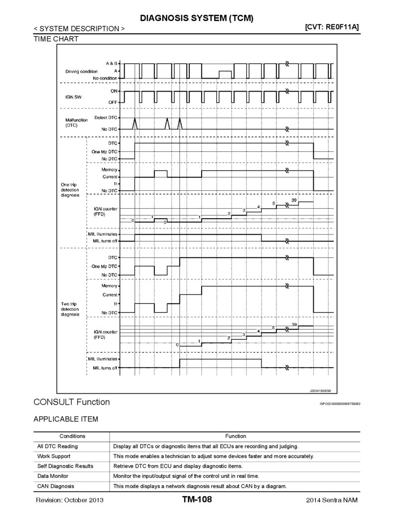
DIAGNOSIS SYSTEM (TCM) ........................... 106
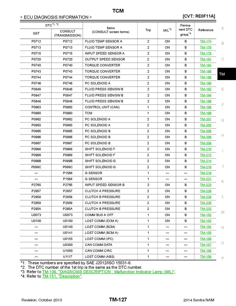
DTC/CIRCUIT DIAGNOSIS ....................... 152
DIAGNOSIS DESCRIPTION ................................... 106
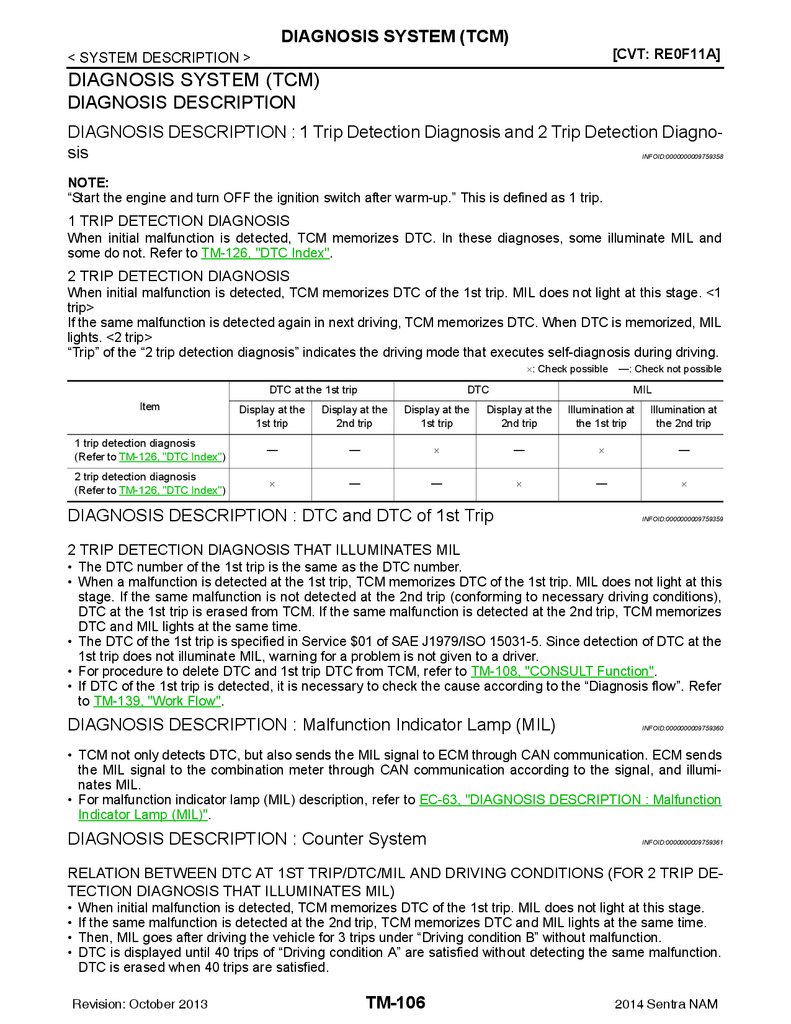
DIAGNOSIS DESCRIPTION : 1 Trip Detection Diagnosis and 2 Trip Detection Diagnosis ................ 106
DIAGNOSIS DESCRIPTION : DTC and DTC of
1st Trip .................................................................. 106
DIAGNOSIS DESCRIPTION : Malfunction Indicator Lamp (MIL) ....................................................... 106
DIAGNOSIS DESCRIPTION : Counter System .... 106
CONSULT Function .............................................. 108
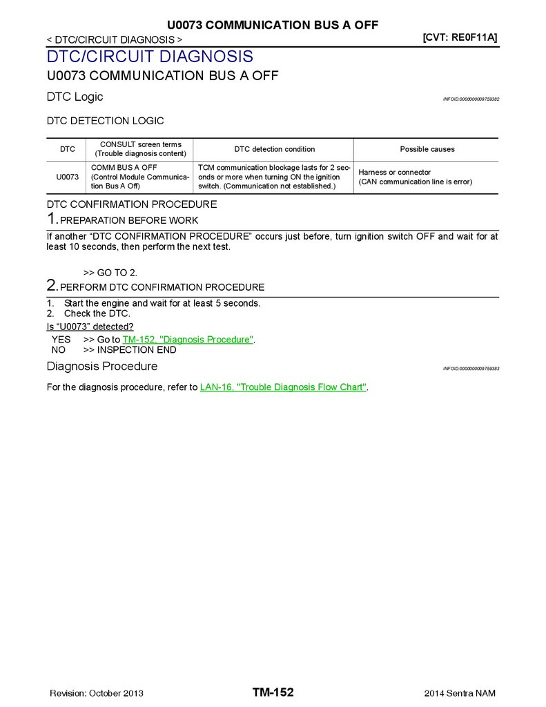
U0073 COMMUNICATION BUS A OFF ......... 152
Description ............................................................. 151
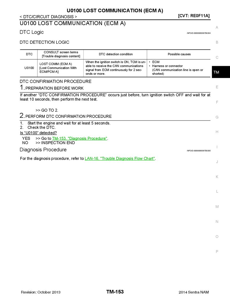
U0100 LOST COMMUNICATION (ECM A) .... 153
DTC Logic .............................................................. 153
Diagnosis Procedure ............................................. 153
C
TM
E
F
G
H
I
J
K
L
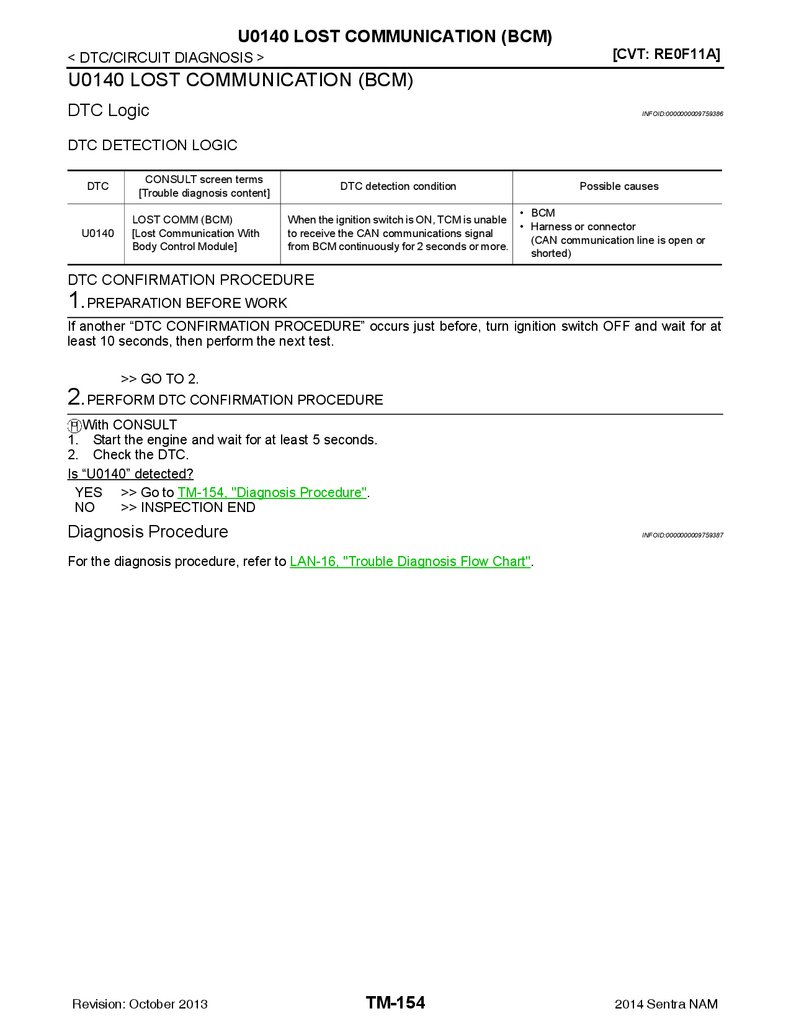
U0140 LOST COMMUNICATION (BCM) ........ 154
DTC Logic .............................................................. 154
Diagnosis Procedure ............................................. 154
TCM .................................................................. 114
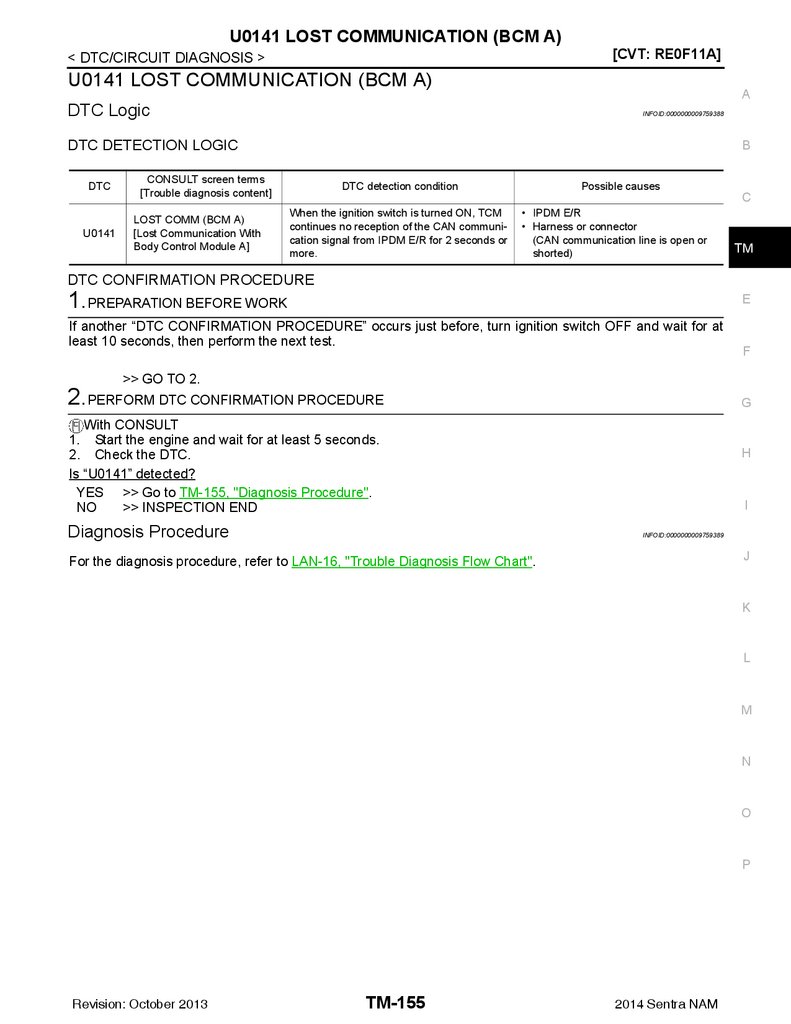
U0141 LOST COMMUNICATION (BCM A) .... 155
Reference Value ................................................... 114
Fail-Safe ................................................................ 122
Protection control .................................................. 124
DTC Inspection Priority Chart ............................... 125
DTC Index ............................................................. 126
DTC Logic .............................................................. 155
Diagnosis Procedure ............................................. 155
M
N
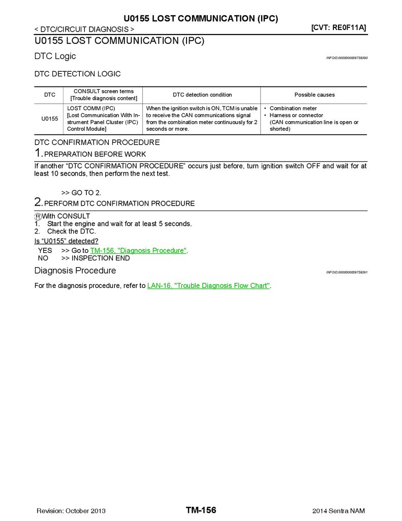
U0155 LOST COMMUNICATION (IPC) .......... 156
DTC Logic .............................................................. 156
Diagnosis Procedure ............................................. 156
U0300 CAN COMMUNICATION DATA .......... 157
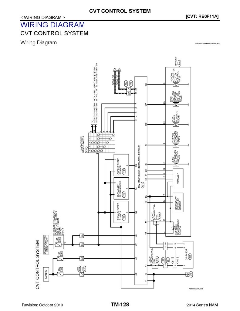
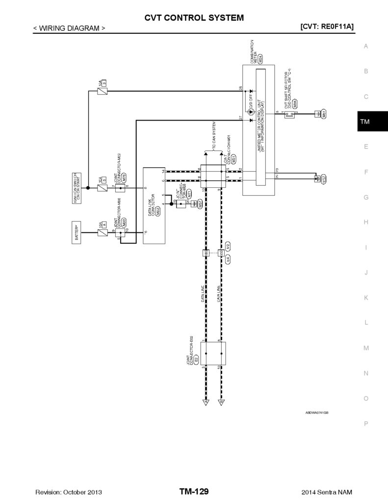
Wiring Diagram ..................................................... 128
DTC Logic .............................................................. 157
Diagnosis Procedure ............................................. 157
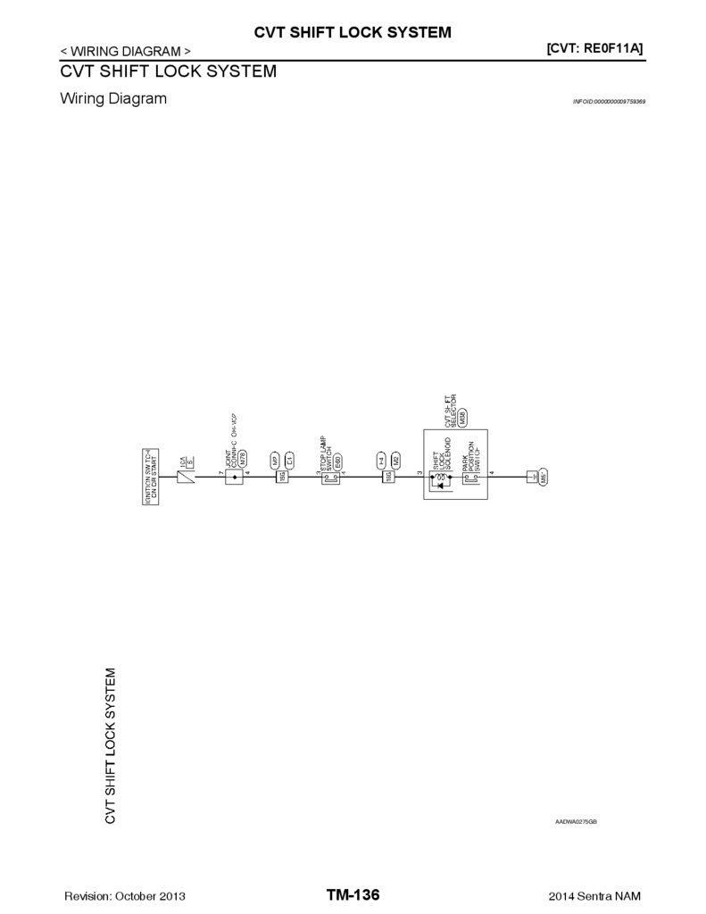
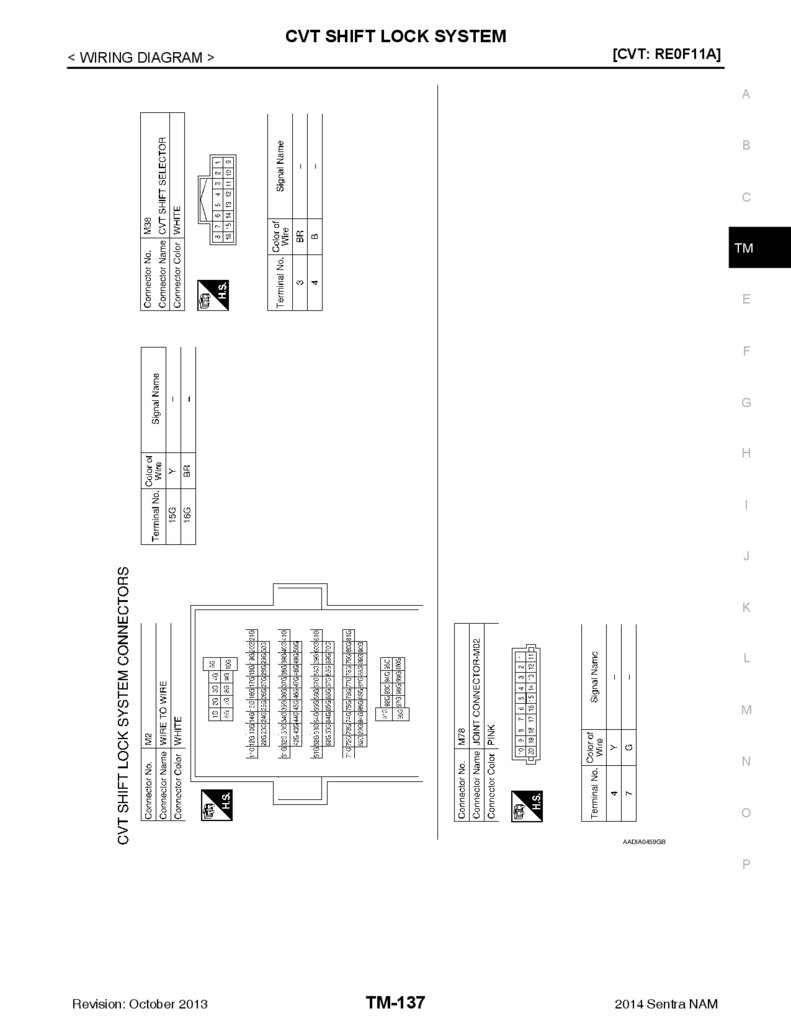
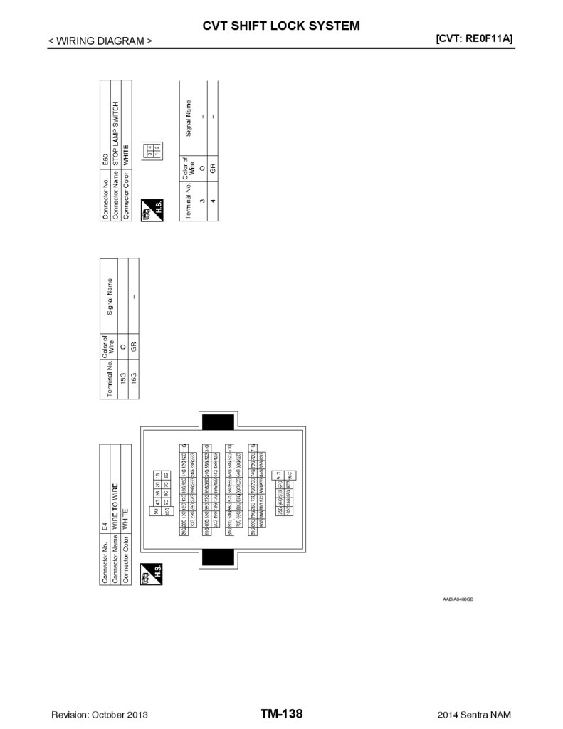
CVT SHIFT LOCK SYSTEM ............................ 136
U1000 CAN COMM CIRCUIT ......................... 158
CVT CONTROL SYSTEM ................................ 128
Wiring Diagram ..................................................... 136
BASIC INSPECTION ................................. 139
Revision: October 2013
B
DTC Logic .............................................................. 152
Diagnosis Procedure ............................................. 152
ECU DIAGNOSIS INFORMATION ............ 114
WIRING DIAGRAM .................................... 128
A
TM-3
Description ............................................................. 158
DTC Logic .............................................................. 158
Diagnosis Procedure ............................................. 158
2014 Sentra NAM
O
P
4.
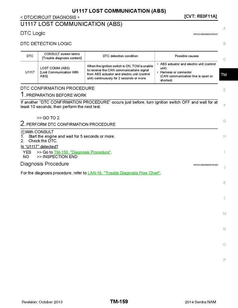
U1117 LOST COMMUNICATION (ABS) ......... 159DTC Logic ..............................................................159
Diagnosis Procedure .............................................159
Diagnosis Procedure ............................................. 191
Component Inspection .......................................... 191
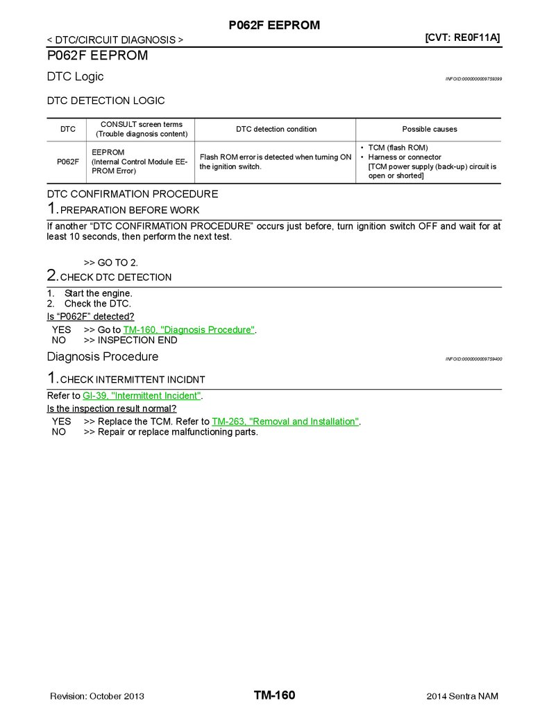
P062F EEPROM .............................................. 160
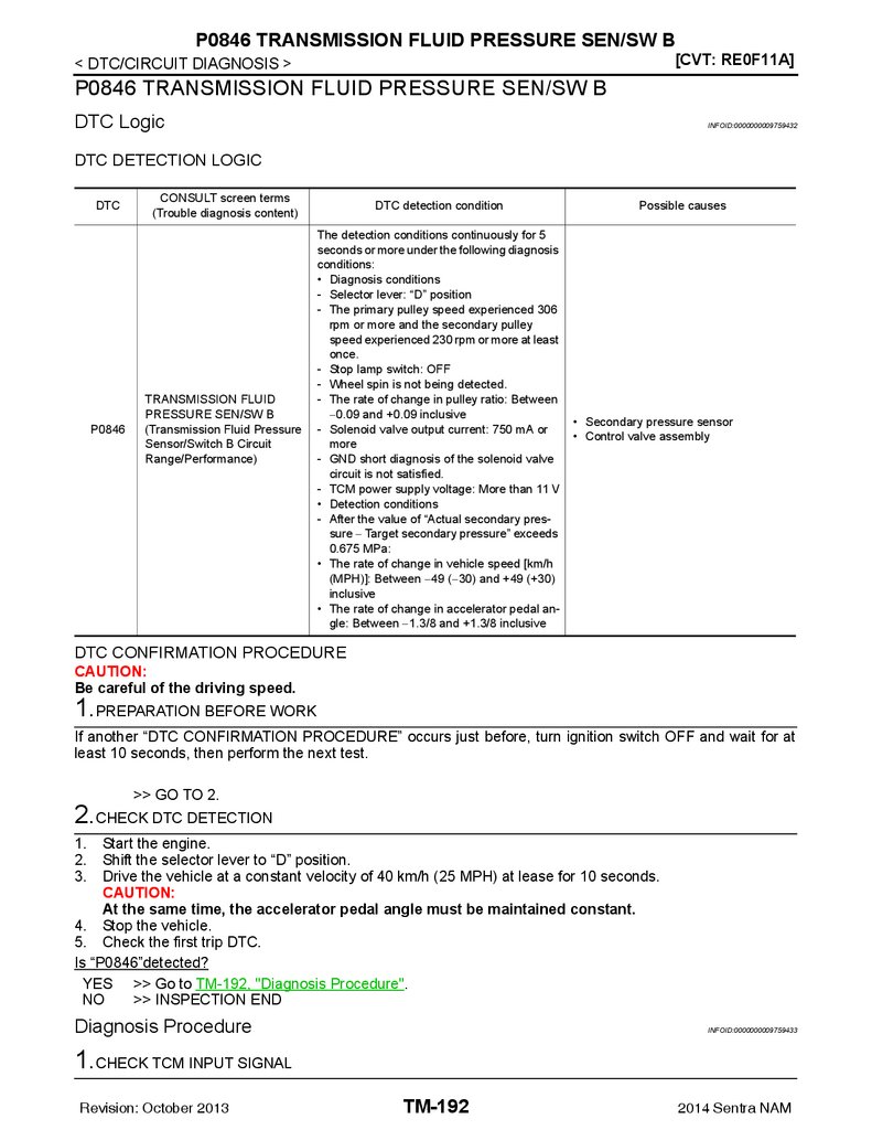
P0846 TRANSMISSION FLUID PRESSURE
SEN/SW B ........................................................ 192
DTC Logic ..............................................................160
Diagnosis Procedure .............................................160
DTC Logic ............................................................. 192
Diagnosis Procedure ............................................. 192
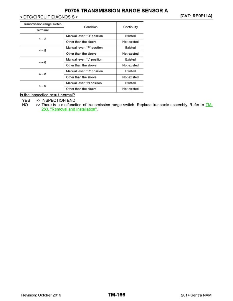
P0705 TRANSMISSION RANGE SENSOR A . 161
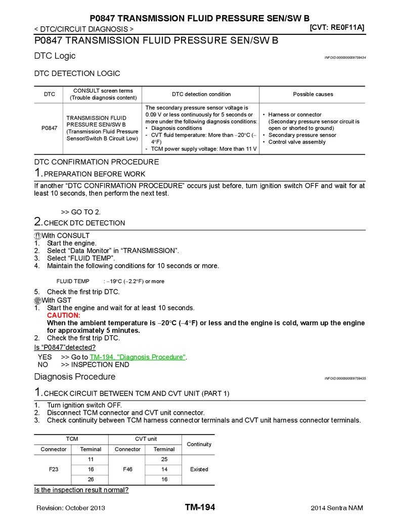
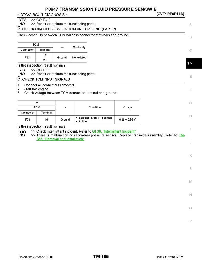
P0847 TRANSMISSION FLUID PRESSURE
SEN/SW B ........................................................ 194
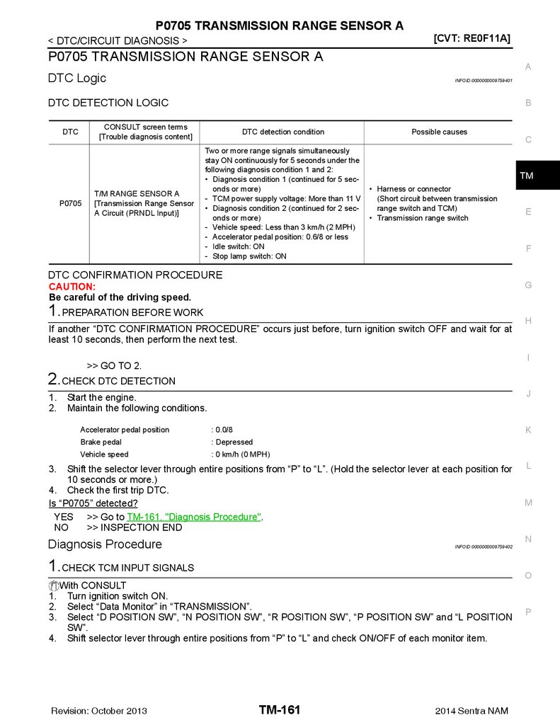
DTC Logic ..............................................................161
Diagnosis Procedure .............................................161
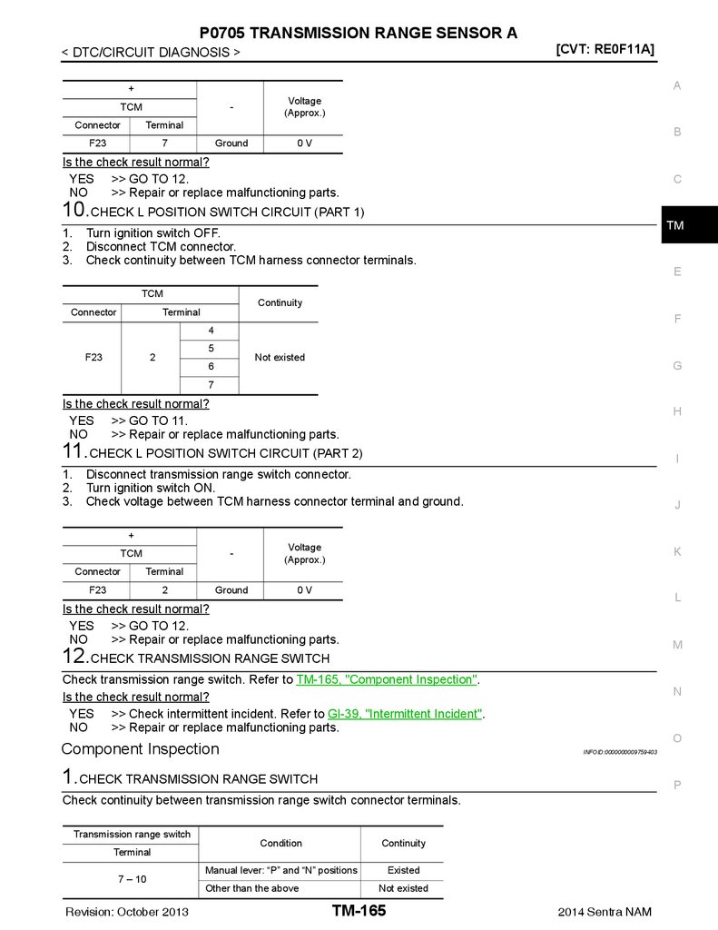
Component Inspection ...........................................165
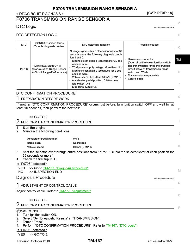
P0706 TRANSMISSION RANGE SENSOR A . 167
DTC Logic ..............................................................167
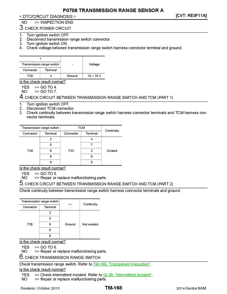
Diagnosis Procedure .............................................167
Component Inspection ...........................................169
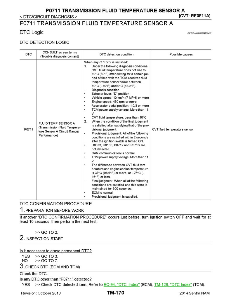
P0711 TRANSMISSION FLUID TEMPERATURE SENSOR A ............................................ 170
DTC Logic ..............................................................170
Diagnosis Procedure .............................................173
Component Inspection ...........................................173
P0712 TRANSMISSION FLUID TEMPERATURE SENSOR A ............................................ 174
DTC Logic ..............................................................174
Diagnosis Procedure .............................................174
Component Inspection ...........................................174
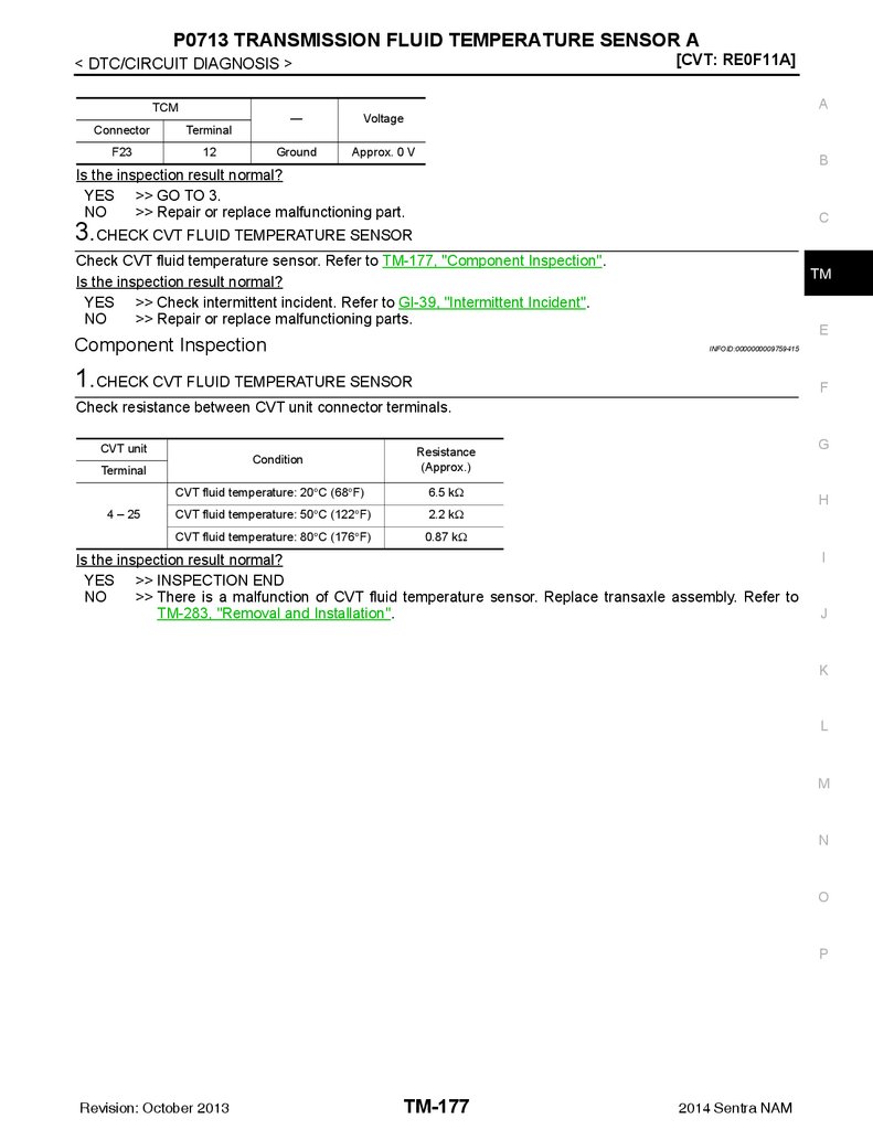
P0713 TRANSMISSION FLUID TEMPERATURE SENSOR A ............................................ 176
DTC Logic ............................................................. 194
Diagnosis Procedure ............................................. 194
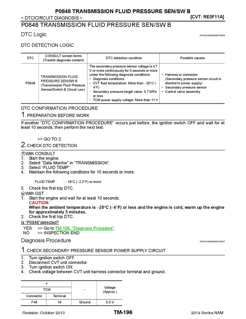
P0848 TRANSMISSION FLUID PRESSURE
SEN/SW B ........................................................ 196
DTC Logic ............................................................. 196
Diagnosis Procedure ............................................. 196
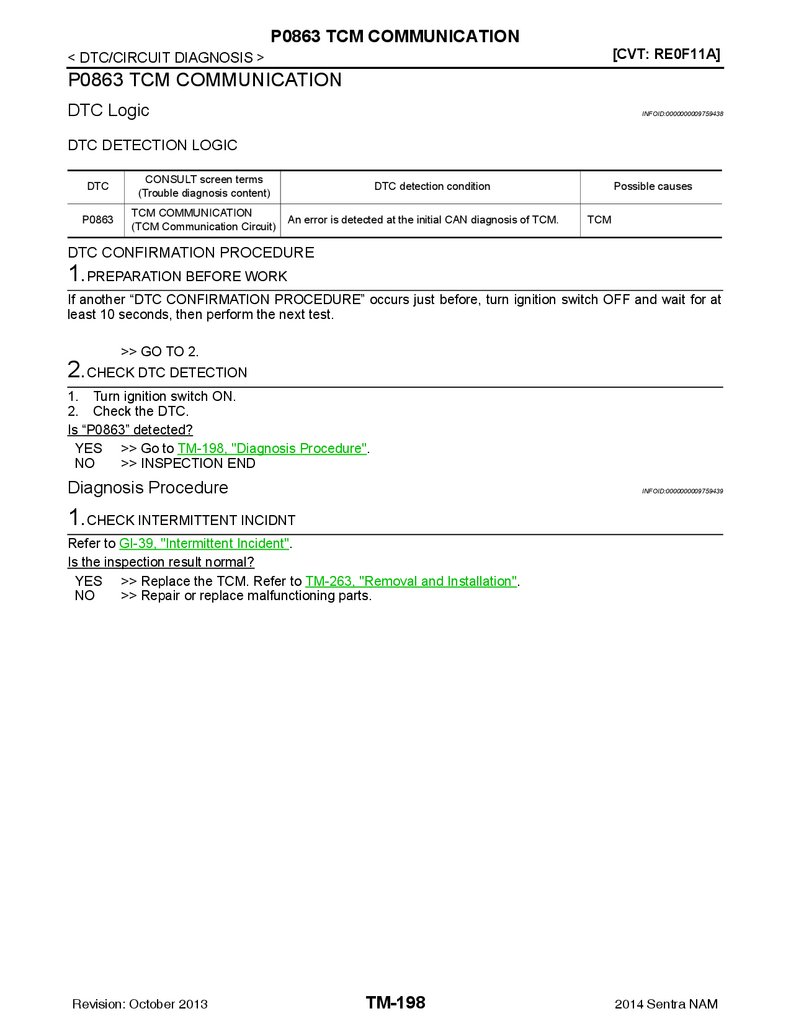
P0863 TCM COMMUNICATION ....................... 198
DTC Logic ............................................................. 198
Diagnosis Procedure ............................................. 198
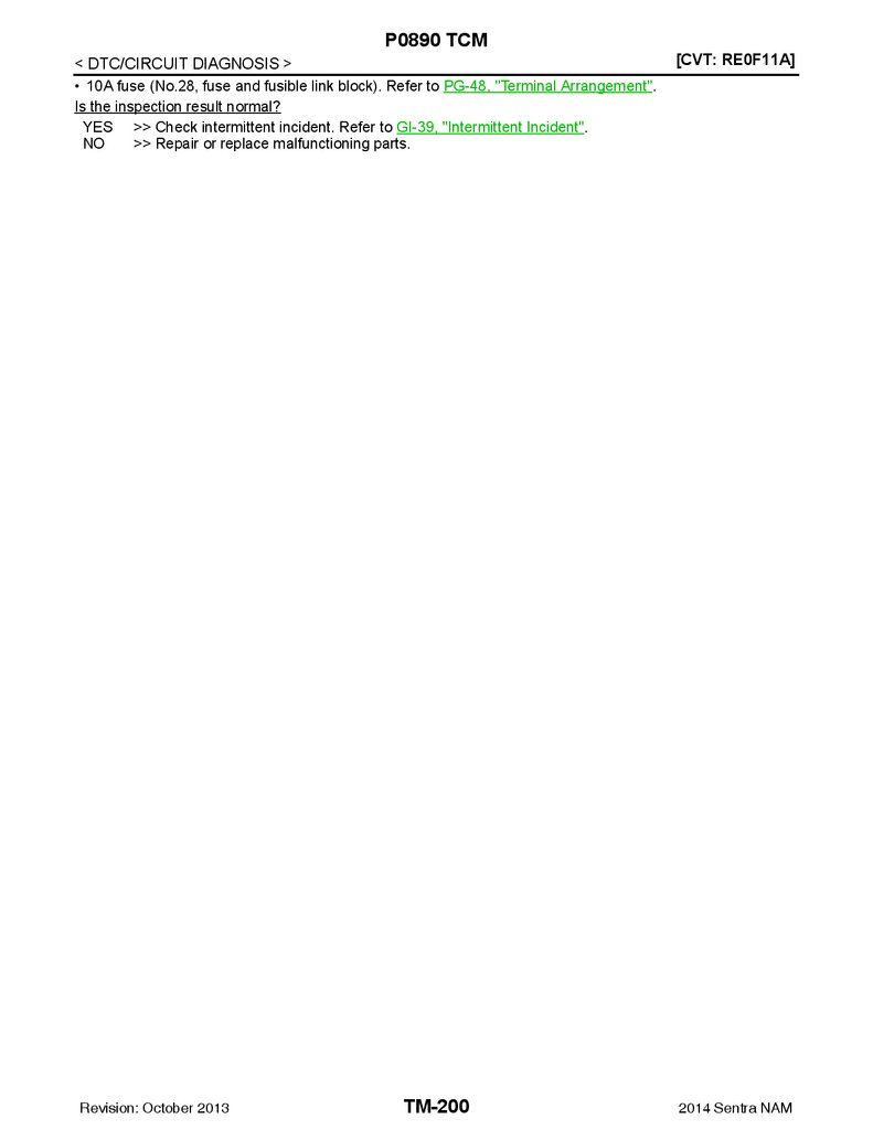
P0890 TCM ....................................................... 199
DTC Logic ............................................................. 199
Diagnosis Procedure ............................................. 199
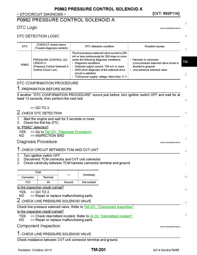
P0962 PRESSURE CONTROL SOLENOID A.. 201
DTC Logic ............................................................. 201
Diagnosis Procedure ............................................. 201
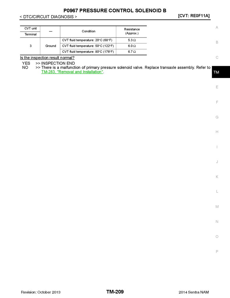
Component Inspection .......................................... 201
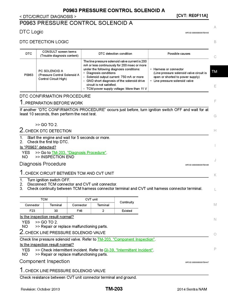
P0963 PRESSURE CONTROL SOLENOID A.. 203
DTC Logic ..............................................................176
Diagnosis Procedure .............................................176
Component Inspection ...........................................177
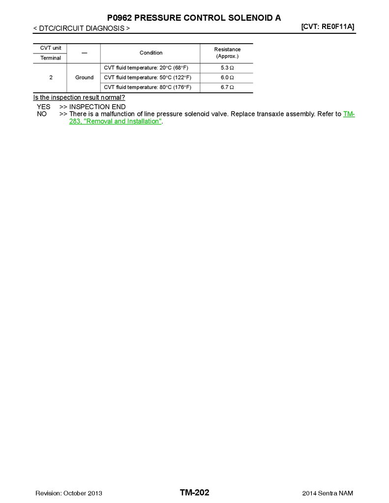
DTC Logic ............................................................. 203
Diagnosis Procedure ............................................. 203
Component Inspection .......................................... 203
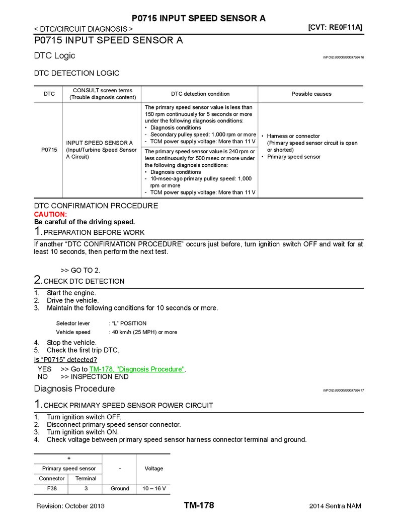
P0715 INPUT SPEED SENSOR A .................. 178
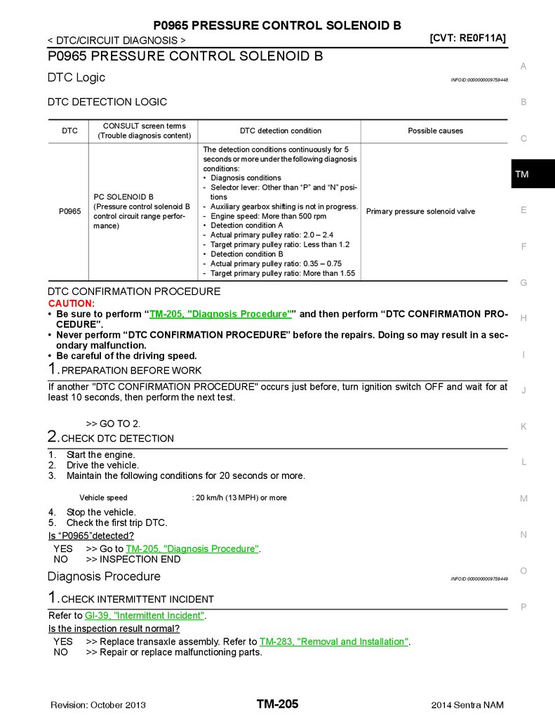
P0965 PRESSURE CONTROL SOLENOID B.. 205
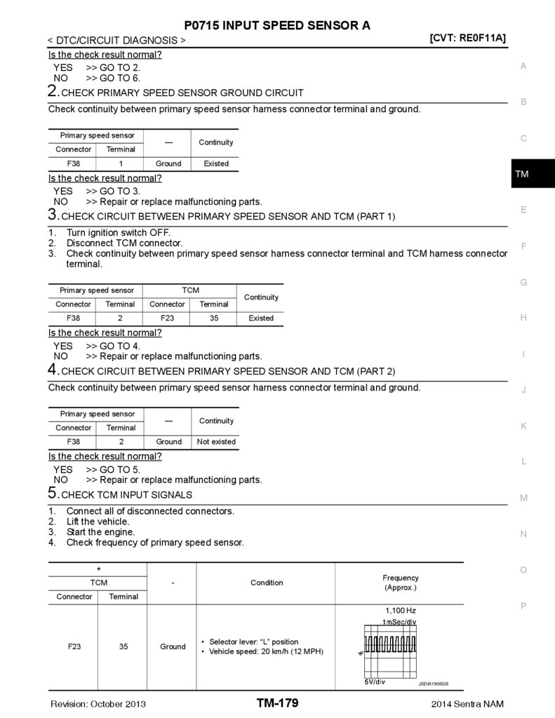
DTC Logic ..............................................................178
Diagnosis Procedure .............................................178
DTC Logic ............................................................. 205
Diagnosis Procedure ............................................. 205
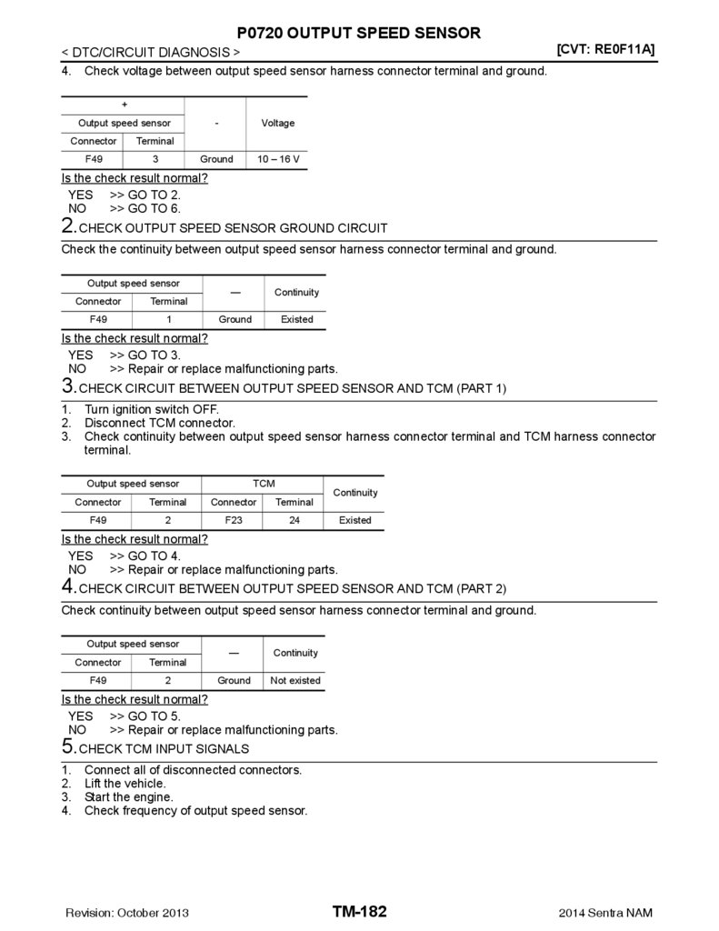
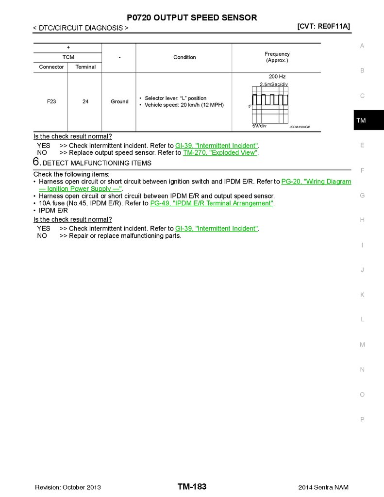
P0720 OUTPUT SPEED SENSOR .................. 181
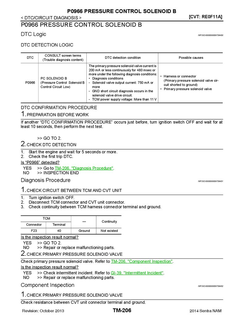
P0966 PRESSURE CONTROL SOLENOID B.. 206
DTC Logic ..............................................................181
Diagnosis Procedure .............................................181
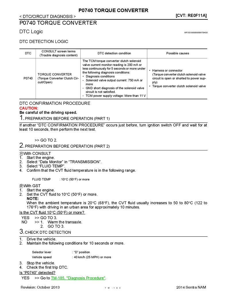
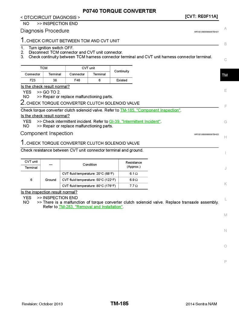
P0740 TORQUE CONVERTER ....................... 184
DTC Logic ..............................................................184
Diagnosis Procedure .............................................185
Component Inspection ...........................................185
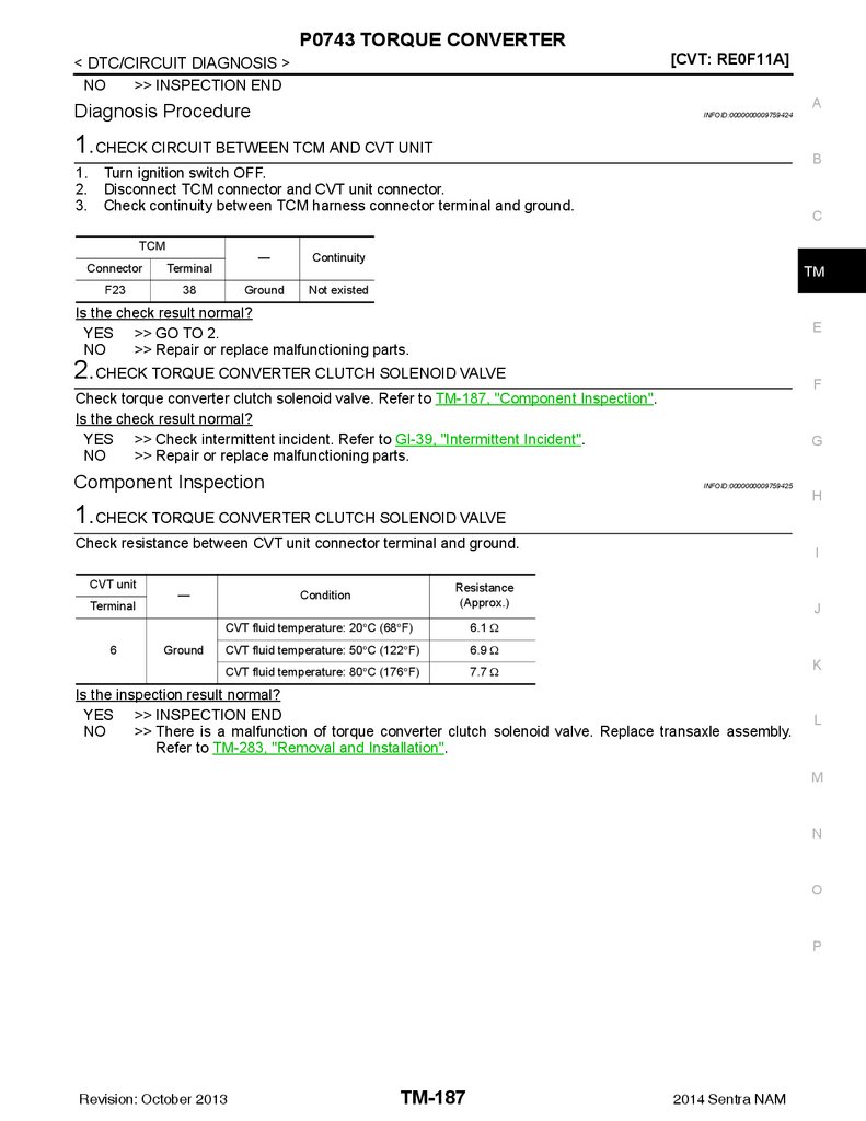
P0743 TORQUE CONVERTER ....................... 186
DTC Logic ..............................................................186
Diagnosis Procedure .............................................187
Component Inspection ...........................................187
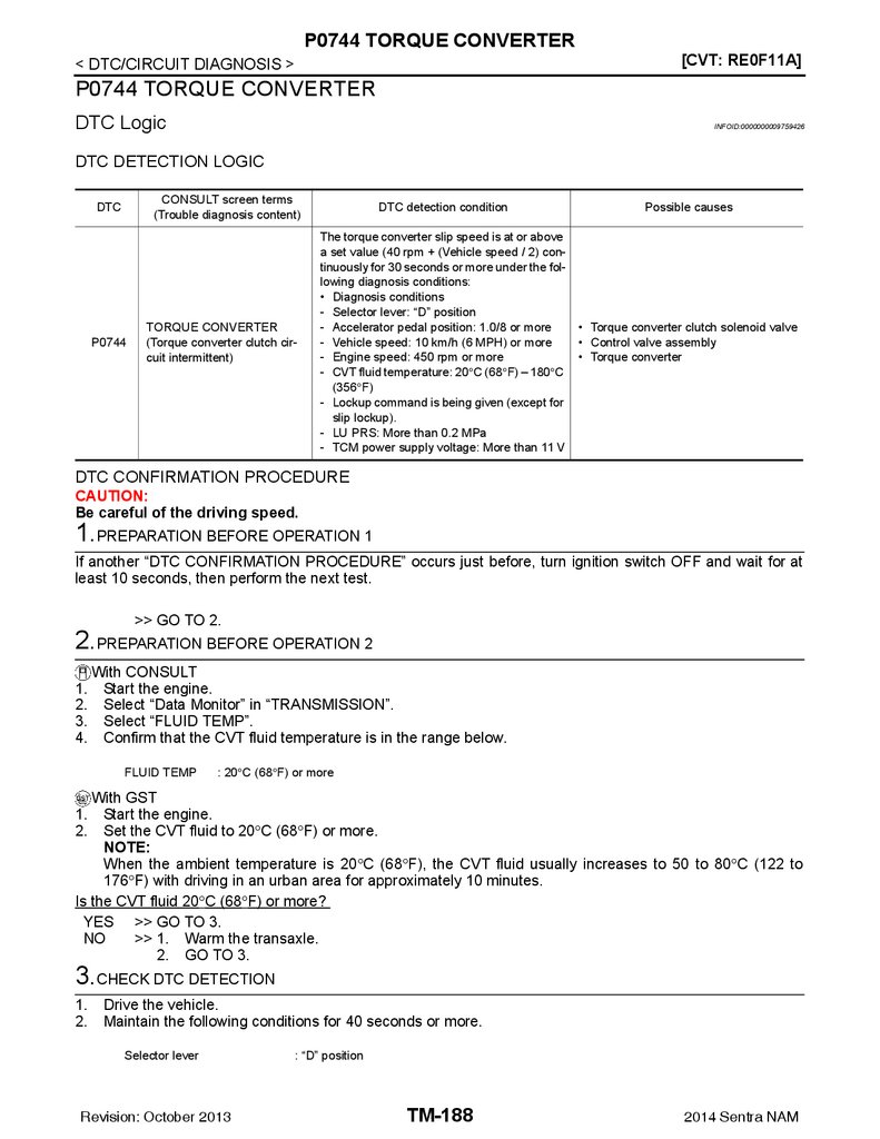
P0744 TORQUE CONVERTER ....................... 188
DTC Logic ..............................................................188
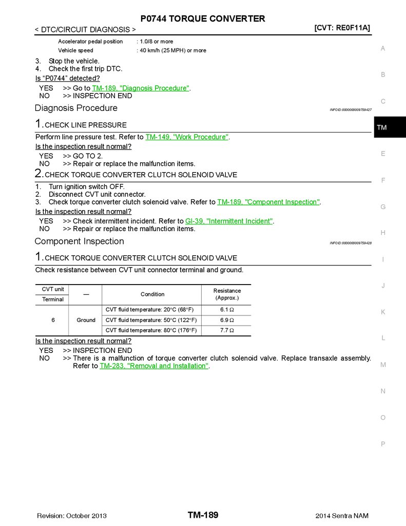
Diagnosis Procedure .............................................189
Component Inspection ...........................................189
P0746 PRESSURE CONTROL SOLENOID A. 190
DTC Logic ..............................................................190
Revision: October 2013
DTC Logic ............................................................. 206
Diagnosis Procedure ............................................. 206
Component Inspection .......................................... 206
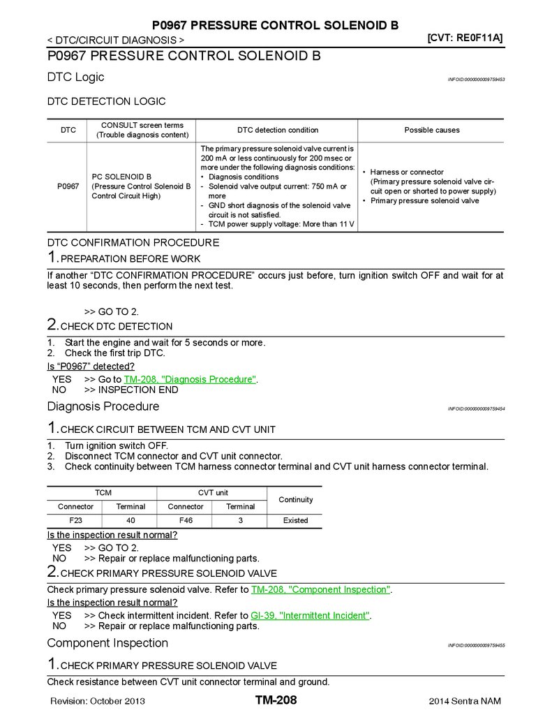
P0967 PRESSURE CONTROL SOLENOID B.. 208
DTC Logic ............................................................. 208
Diagnosis Procedure ............................................. 208
Component Inspection .......................................... 208
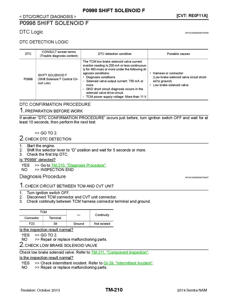
P0998 SHIFT SOLENOID F ............................. 210
DTC Logic ............................................................. 210
Diagnosis Procedure ............................................. 210
Component Inspection .......................................... 211
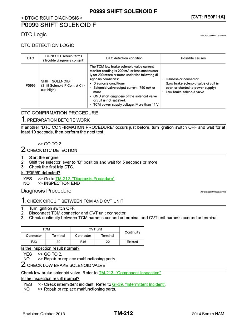
P0999 SHIFT SOLENOID F ............................. 212
DTC Logic ............................................................. 212
Diagnosis Procedure ............................................. 212
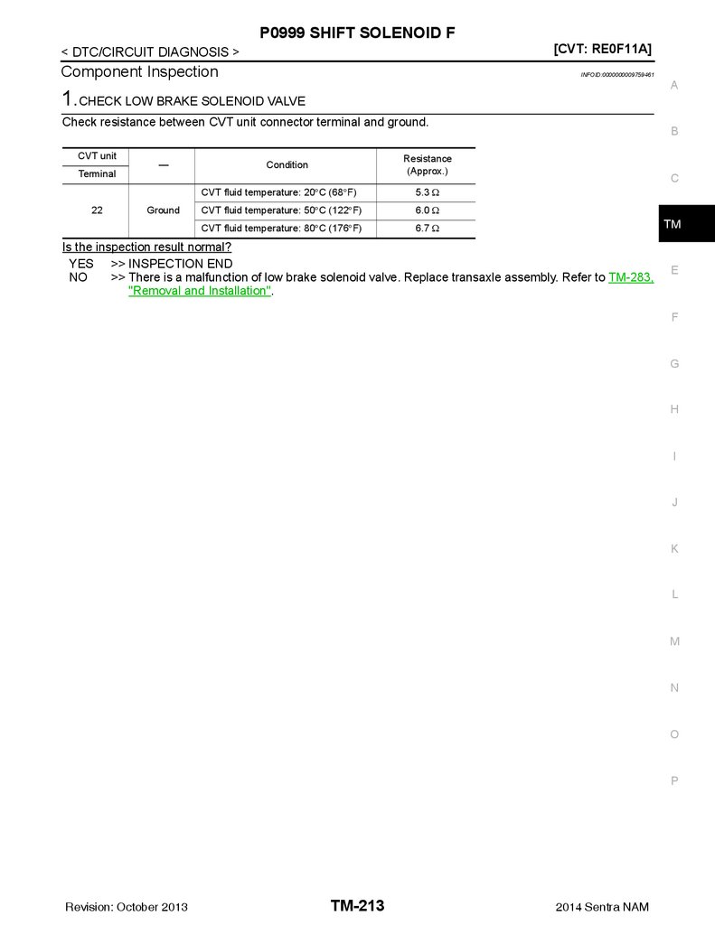
Component Inspection .......................................... 213
P099B SHIFT SOLENOID G ............................ 214
DTC Logic ............................................................. 214
TM-4
2014 Sentra NAM
5.
Diagnosis Procedure ............................................. 214Component Inspection .......................................... 214
CVT CONTROL SYSTEM ............................... 244
P099C SHIFT SOLENOID G ............................ 216
PERIODIC MAINTENANCE ...................... 250
DTC Logic ............................................................. 216
Diagnosis Procedure ............................................. 216
Component Inspection .......................................... 216
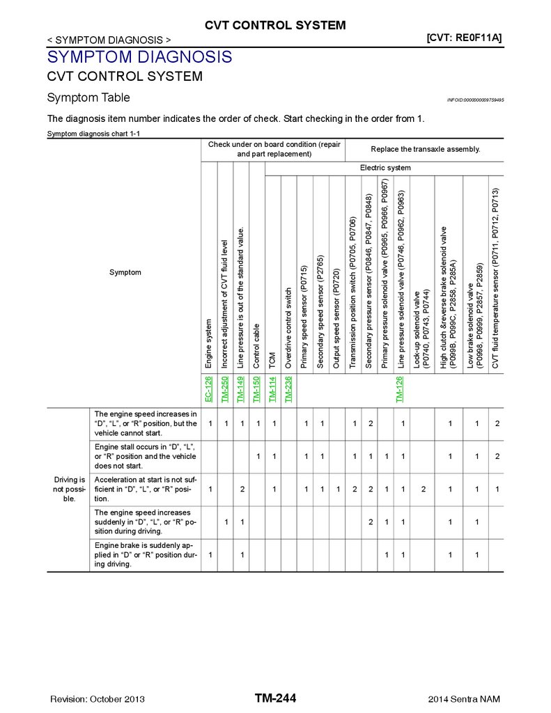
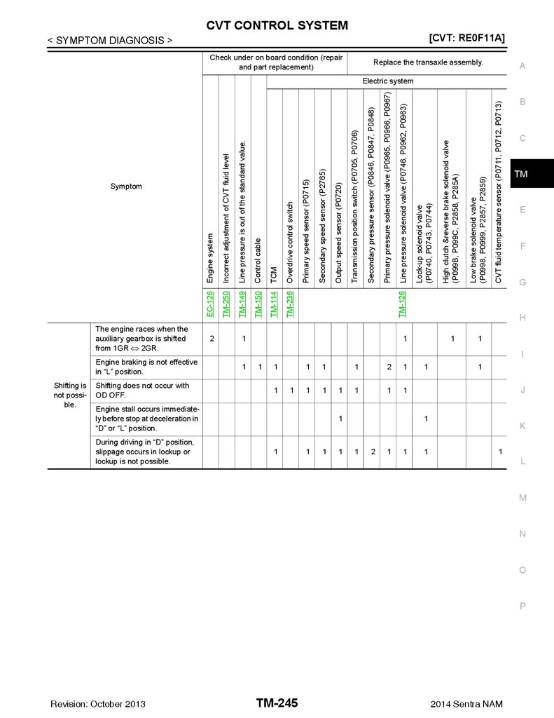
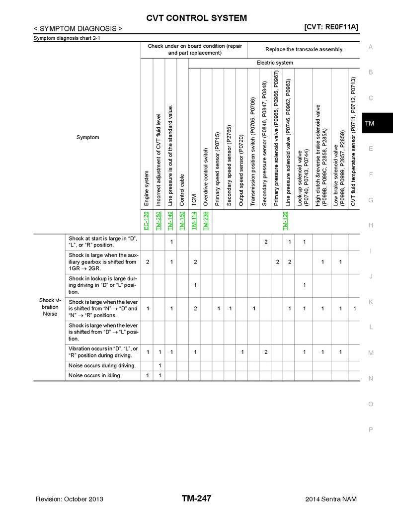
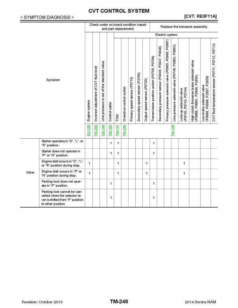
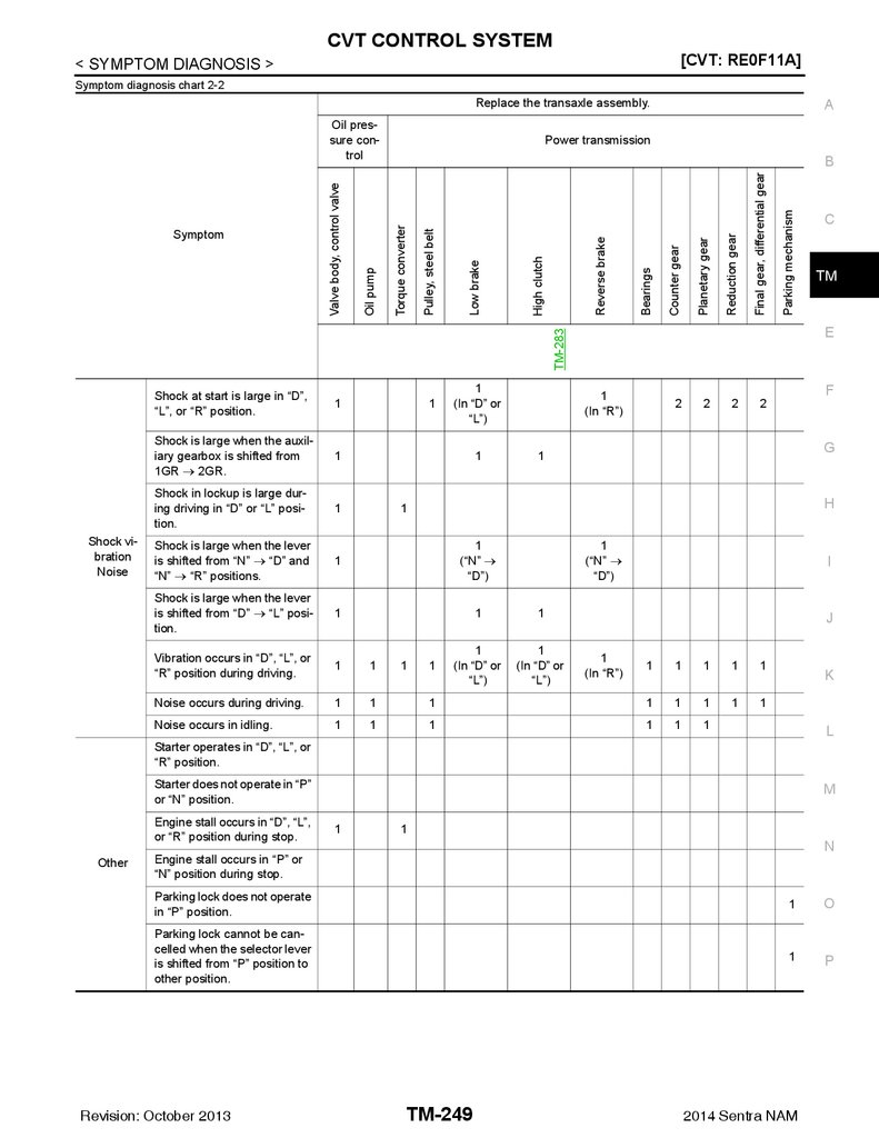
Symptom Table ..................................................... 244
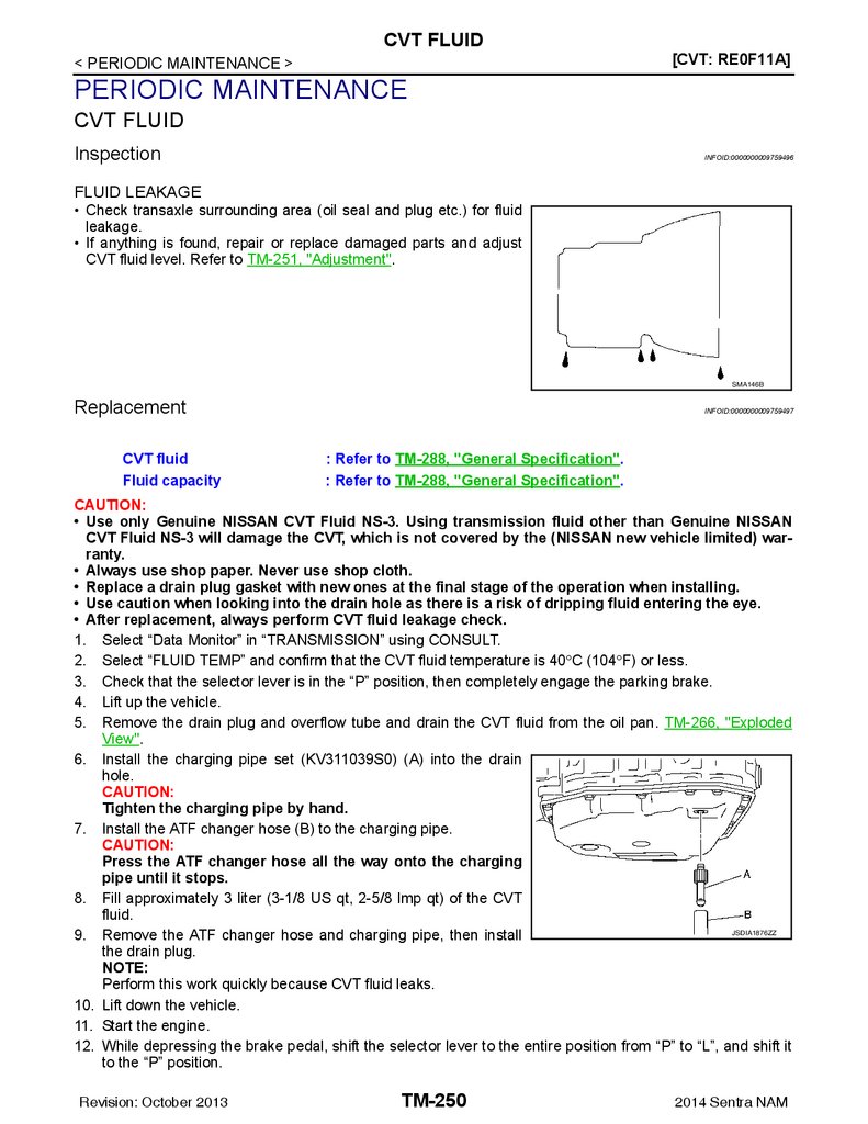
CVT FLUID ...................................................... 250
B
Inspection .............................................................. 250
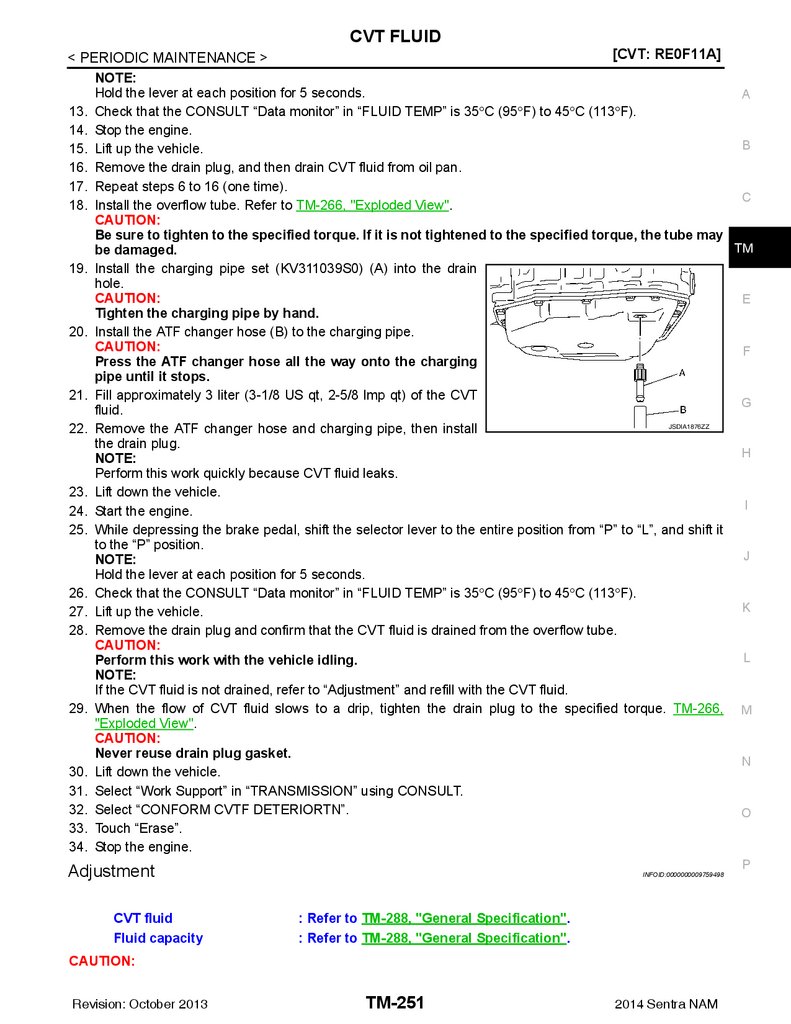
Replacement ......................................................... 250
Adjustment ............................................................. 251
C
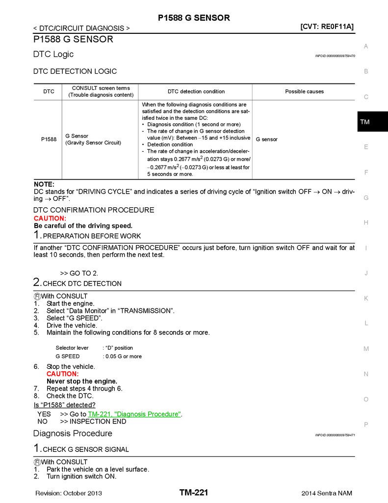
P1586 G SENSOR ............................................ 218
DTC Logic ............................................................. 218
Diagnosis Procedure ............................................. 218
P1588 G SENSOR ............................................ 221
REMOVAL AND INSTALLATION ............. 253
CVT SHIFT SELECTOR .................................. 253 TM
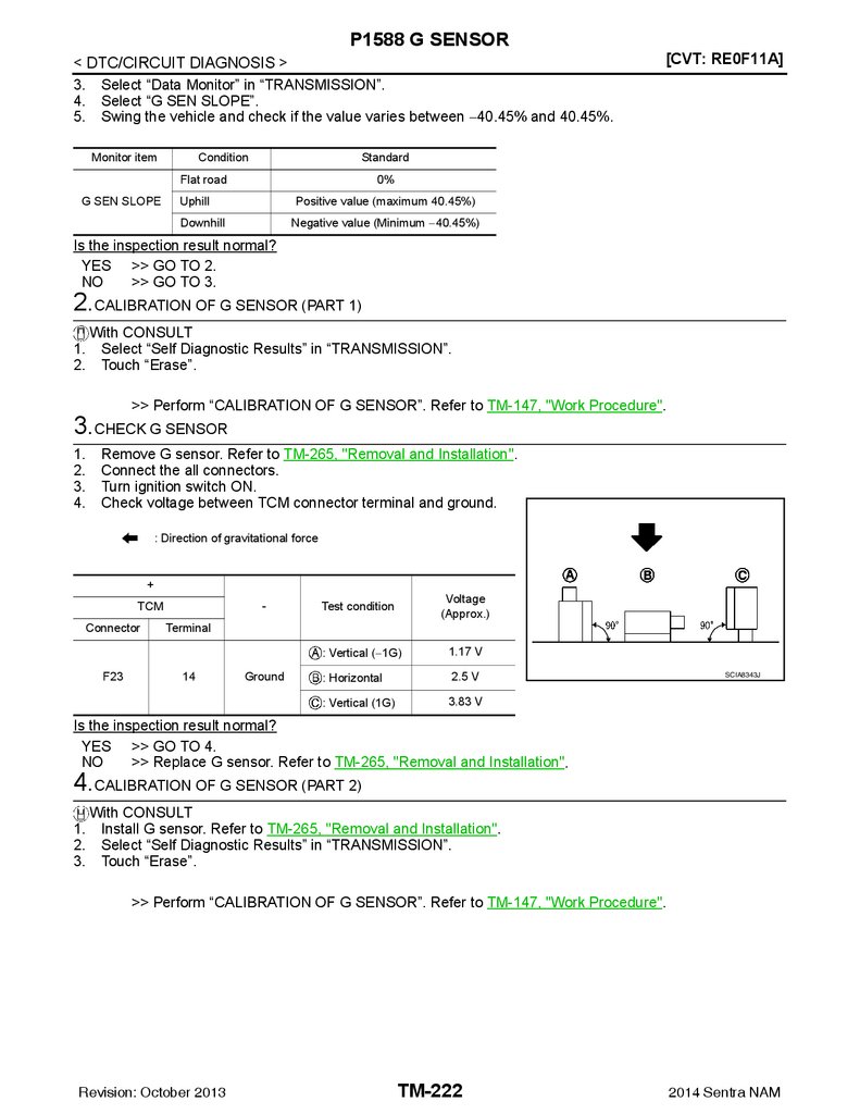
DTC Logic ............................................................. 221
Diagnosis Procedure ............................................. 221
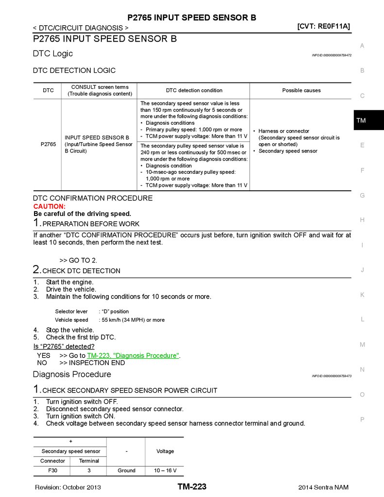
P2765 INPUT SPEED SENSOR B ................... 223
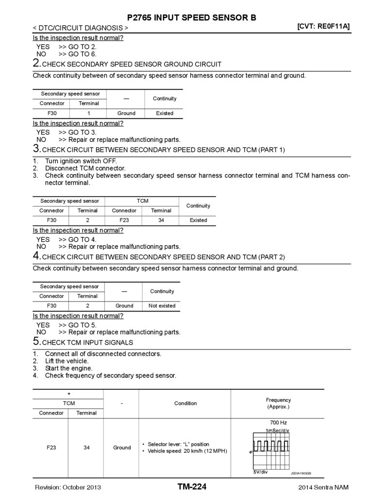
DTC Logic ............................................................. 223
Diagnosis Procedure ............................................. 223
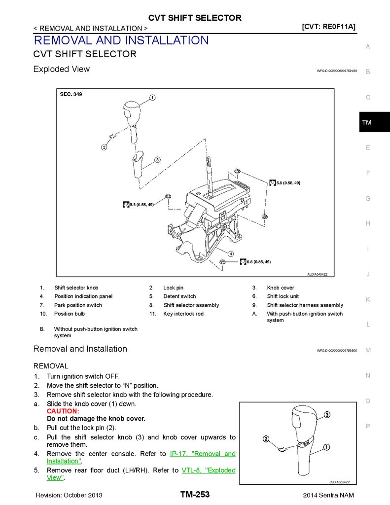
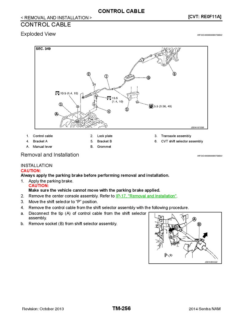
Exploded View ....................................................... 253
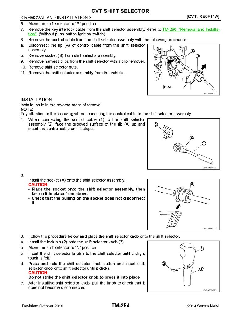
Removal and Installation ....................................... 253
Inspection .............................................................. 255
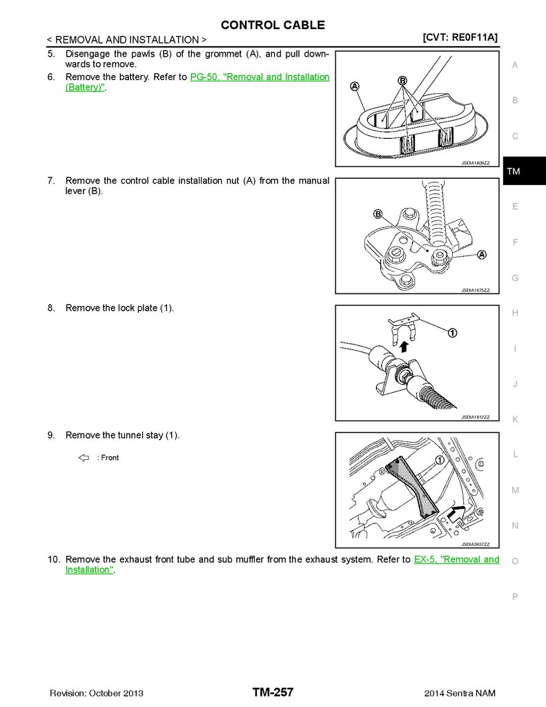
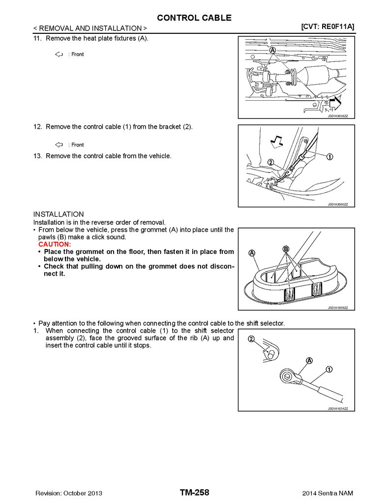
Exploded View ....................................................... 256
Removal and Installation ....................................... 256
Inspection and Adjustment .................................... 259
F
KEY INTERLOCK CABLE .............................. 260
G
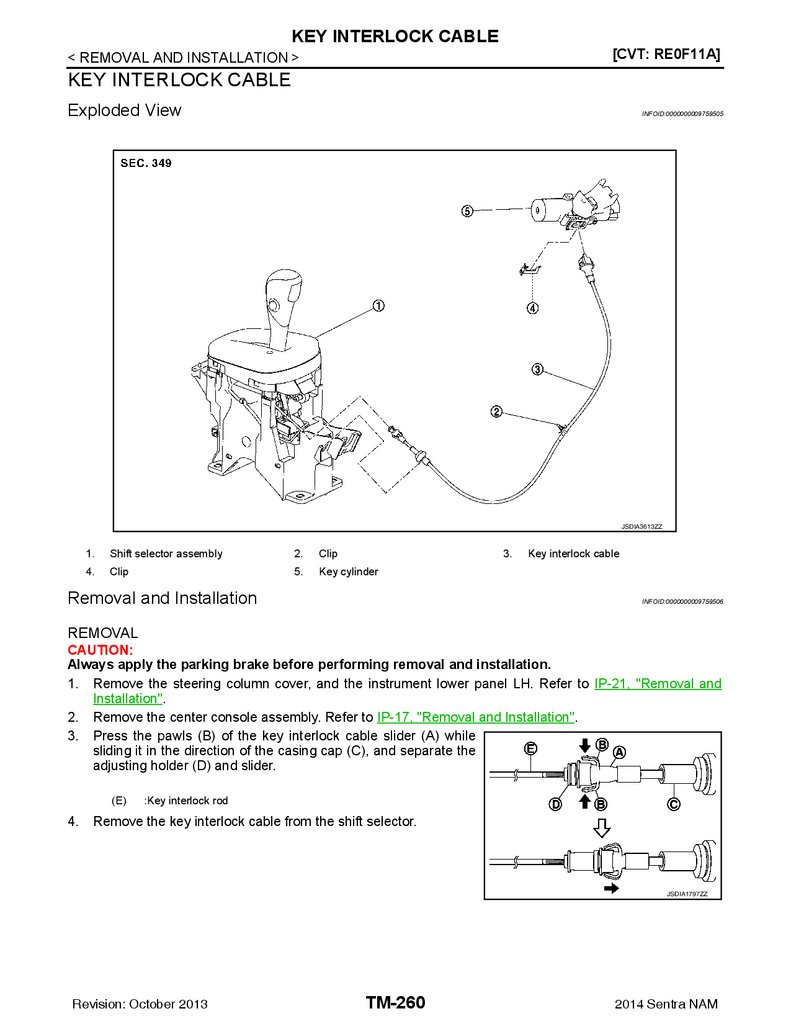
Exploded View ....................................................... 260
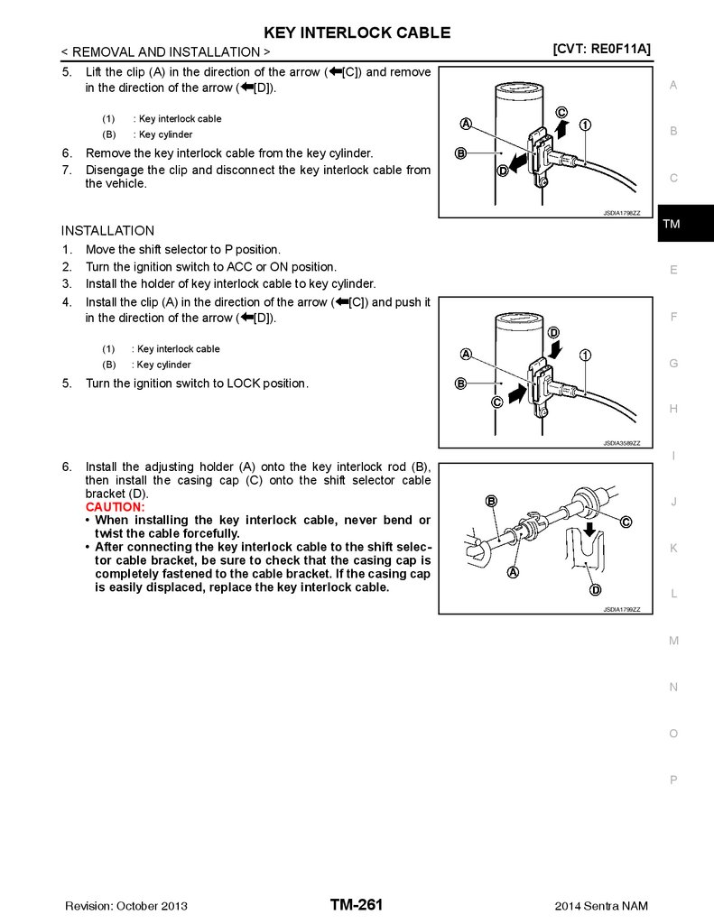
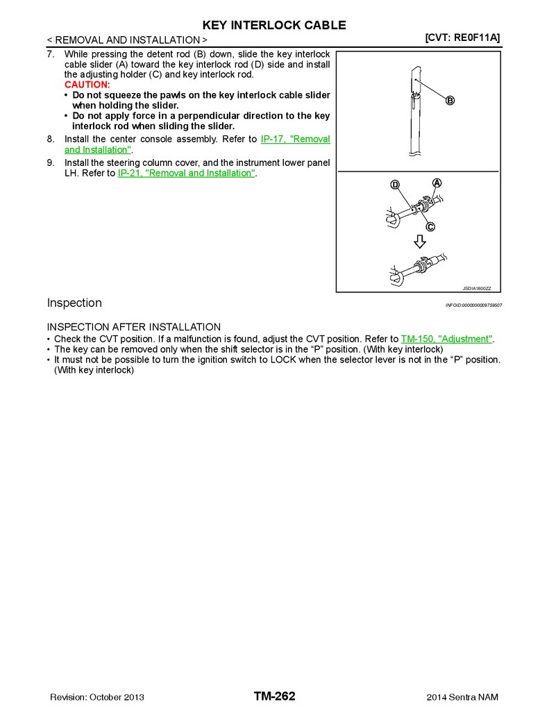
Removal and Installation ....................................... 260
Inspection .............................................................. 262
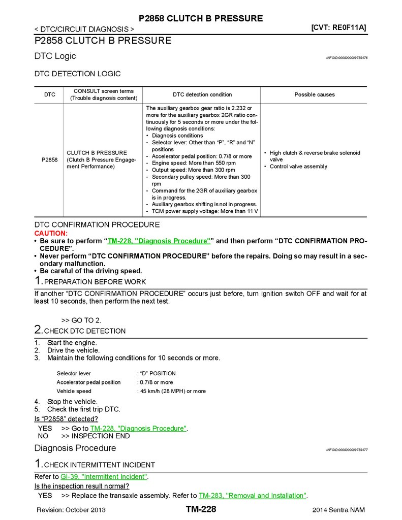
P2858 CLUTCH B PRESSURE ....................... 228
DTC Logic ............................................................. 228
Diagnosis Procedure ............................................. 228
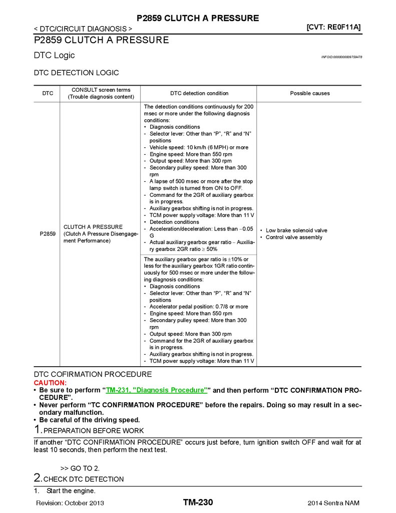
P2859 CLUTCH A PRESSURE ....................... 230
Exploded View ....................................................... 263
Removal and Installation ....................................... 263
Adjustment ............................................................. 263
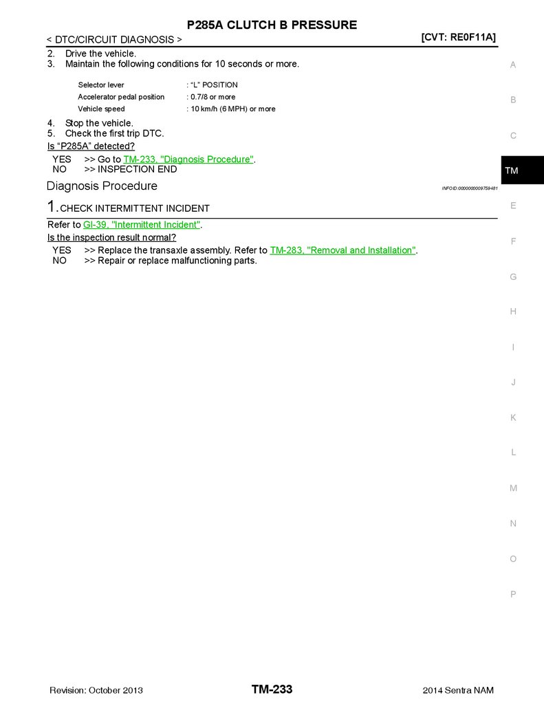
P285A CLUTCH B PRESSURE ....................... 232
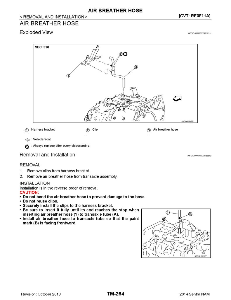
AIR BREATHER HOSE .................................. 264
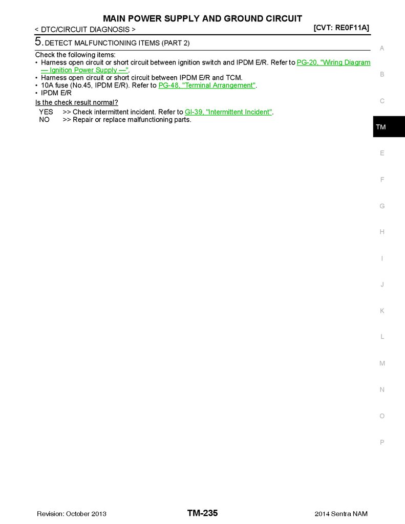
MAIN POWER SUPPLY AND GROUND CIRCUIT .................................................................. 234
Exploded View ....................................................... 264
Removal and Installation ....................................... 264
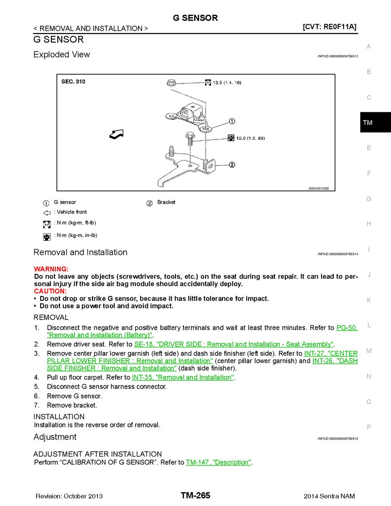
G SENSOR ...................................................... 265
Exploded View ....................................................... 265
Removal and Installation ....................................... 265
Adjustment ............................................................. 265
Diagnosis Procedure ............................................. 234
OVERDRIVE CONTROL SWITCH ................... 236
Component Function Check .................................. 236
Diagnosis Procedure ............................................. 236
Component Inspection (Overdrive Control Switch)
.. 237
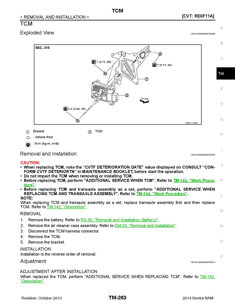
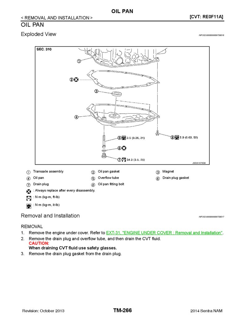
OIL PAN .......................................................... 266
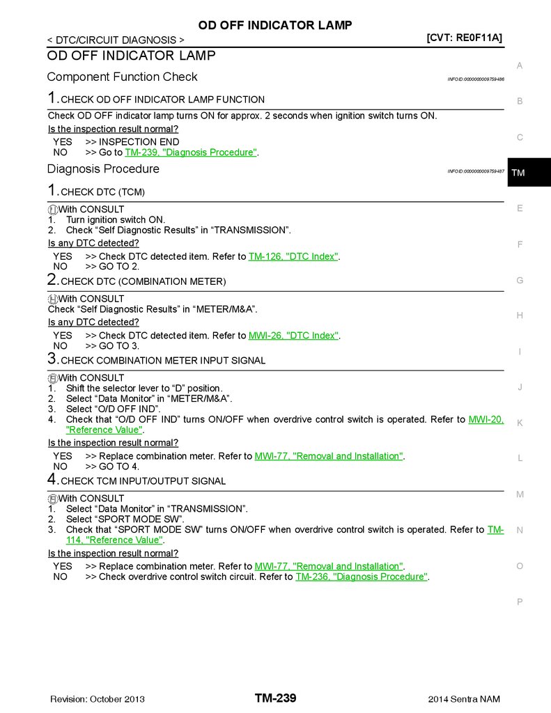
OD OFF INDICATOR LAMP ............................ 239
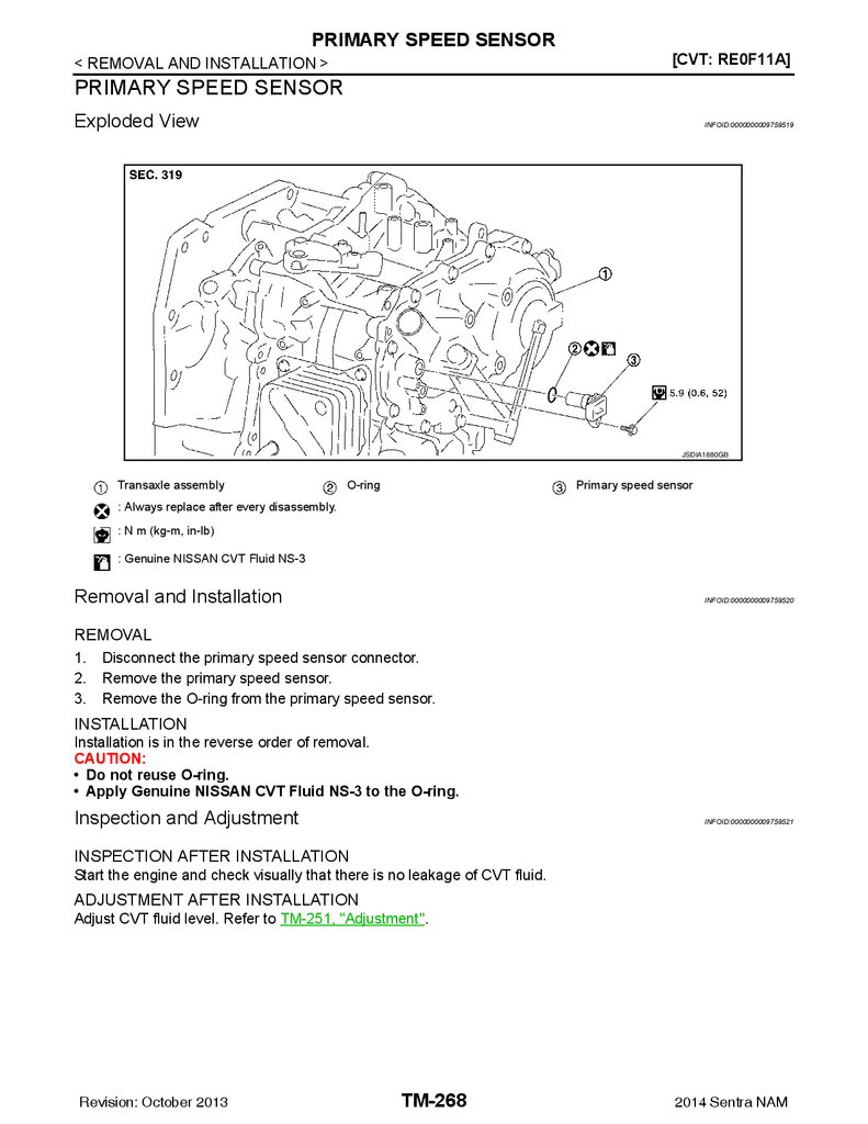
PRIMARY SPEED SENSOR ........................... 268
Component Function Check .................................. 239
Diagnosis Procedure ............................................. 239
Exploded View ....................................................... 266
Removal and Installation ....................................... 266
Inspection .............................................................. 267
Exploded View ....................................................... 268
Removal and Installation ....................................... 268
Inspection and Adjustment .................................... 268
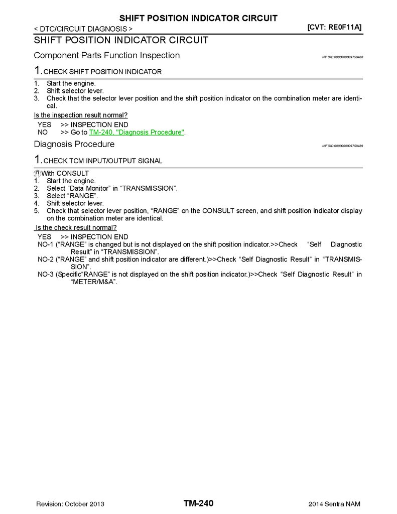
SHIFT POSITION INDICATOR CIRCUIT ......... 240
Component Parts Function Inspection .................. 240
Diagnosis Procedure ............................................. 240
SECONDARY SPEED SENSOR .................... 269
Exploded View ....................................................... 269
Removal and Installation ....................................... 269
Inspection and Adjustment .................................... 269
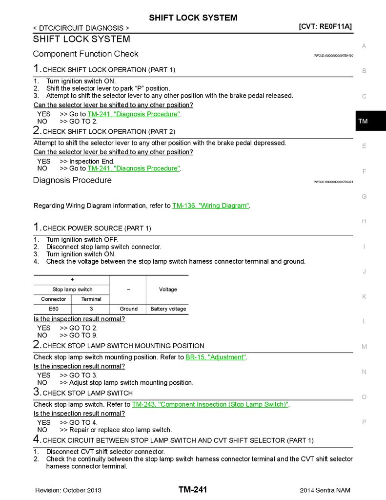
SHIFT LOCK SYSTEM ..................................... 241
Component Function Check .................................. 241
Diagnosis Procedure ............................................. 241
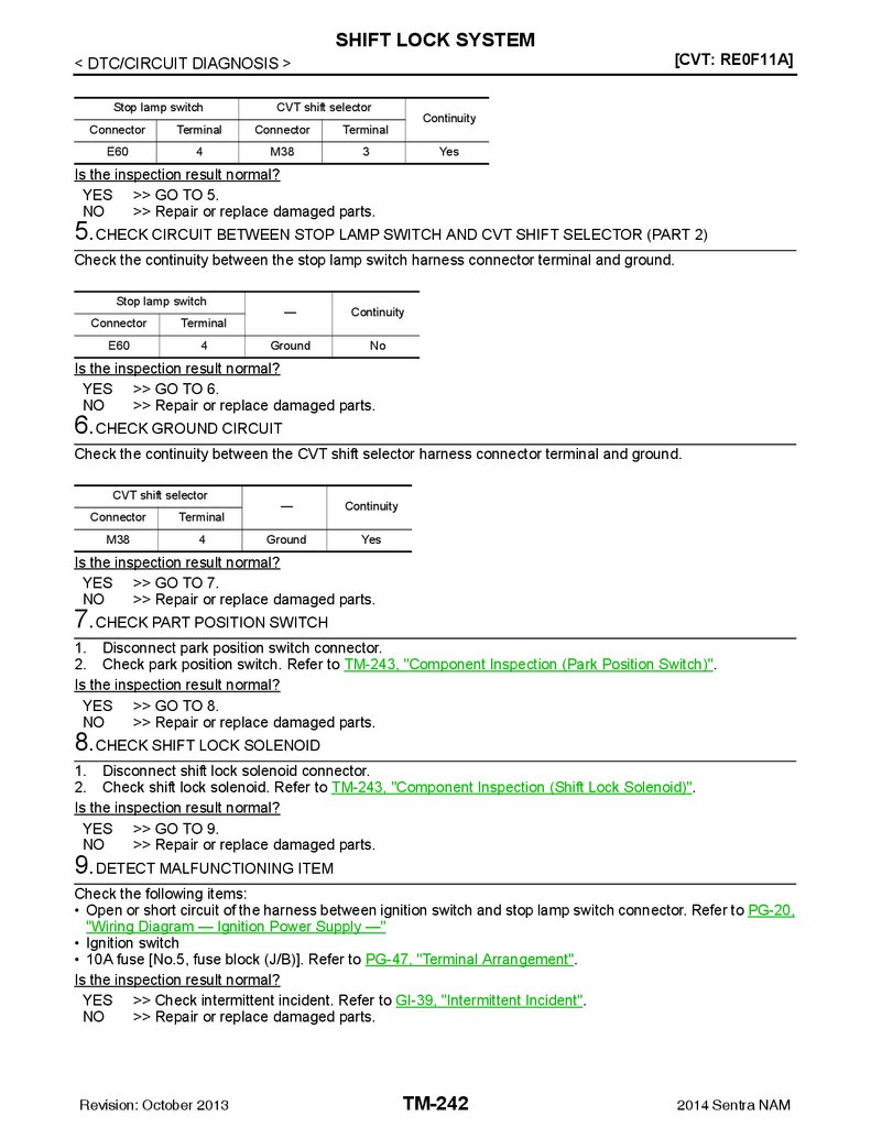
Component Inspection (Shift Lock Solenoid) ........ 243
Component Inspection (Park Position Switch) ...... 243
Component Inspection (Stop Lamp Switch) .......... 243
SYMPTOM DIAGNOSIS ............................ 244
Revision: October 2013
H
TCM ................................................................. 263
DTC Logic ............................................................. 230
Diagnosis Procedure ............................................. 231
DTC Logic ............................................................. 232
Diagnosis Procedure ............................................. 233
E
CONTROL CABLE .......................................... 256
P2857 CLUTCH A PRESSURE ....................... 226
DTC Logic ............................................................. 226
Diagnosis Procedure ............................................. 226
A
OUTPUT SPEED SENSOR ............................. 270
Exploded View ....................................................... 270
Removal and Installation ....................................... 270
Inspection and Adjustment .................................... 270
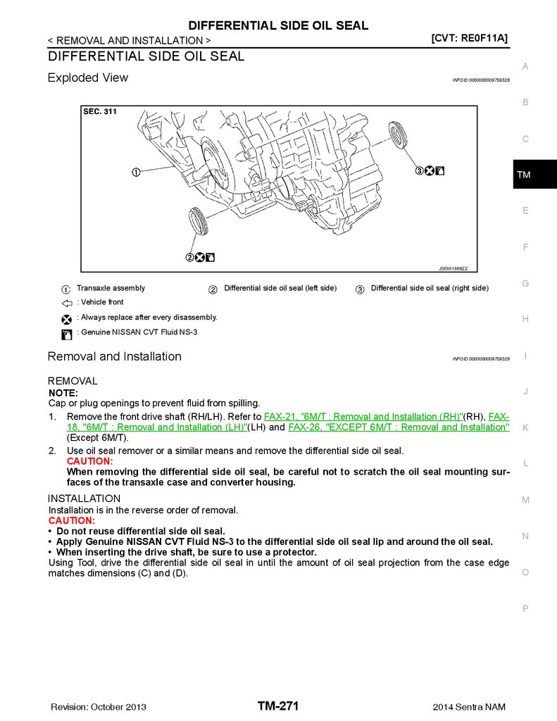
DIFFERENTIAL SIDE OIL SEAL .................... 271
TM-5
2014 Sentra NAM
I
J
K
L
M
N
O
P
6.
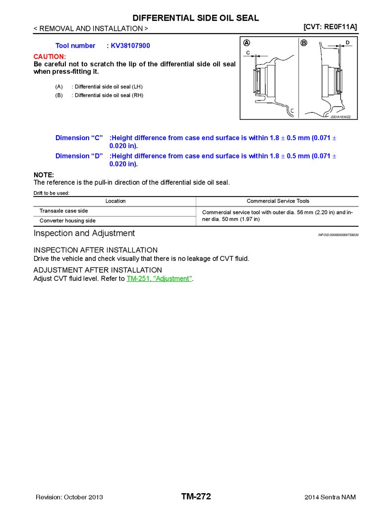
Exploded View .......................................................271Removal and Installation .......................................271
Inspection and Adjustment ....................................272
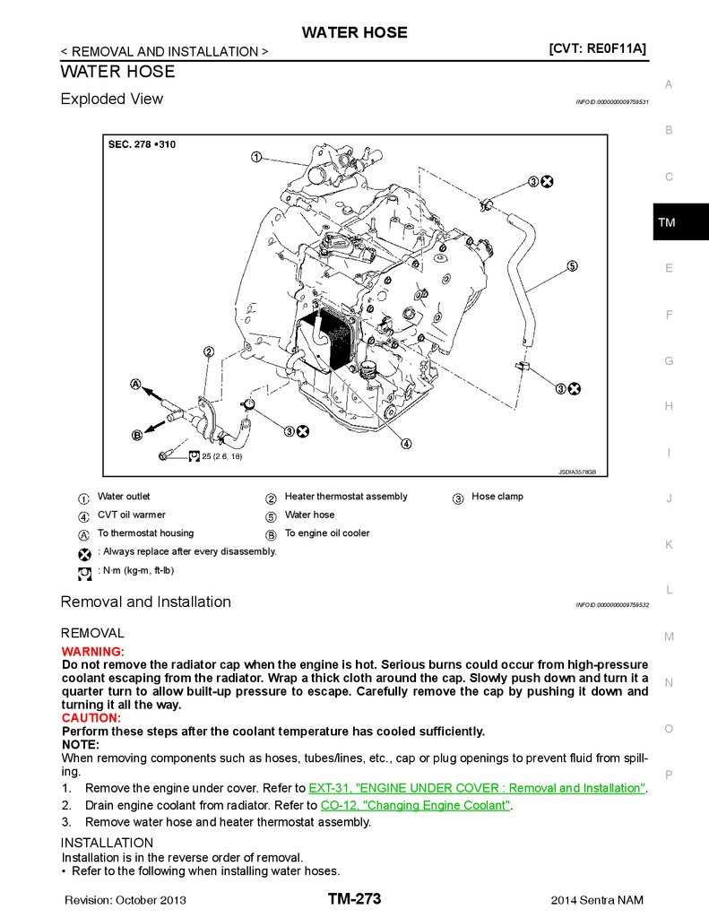
WATER HOSE ................................................. 273
Exploded View .......................................................273
Removal and Installation .......................................273
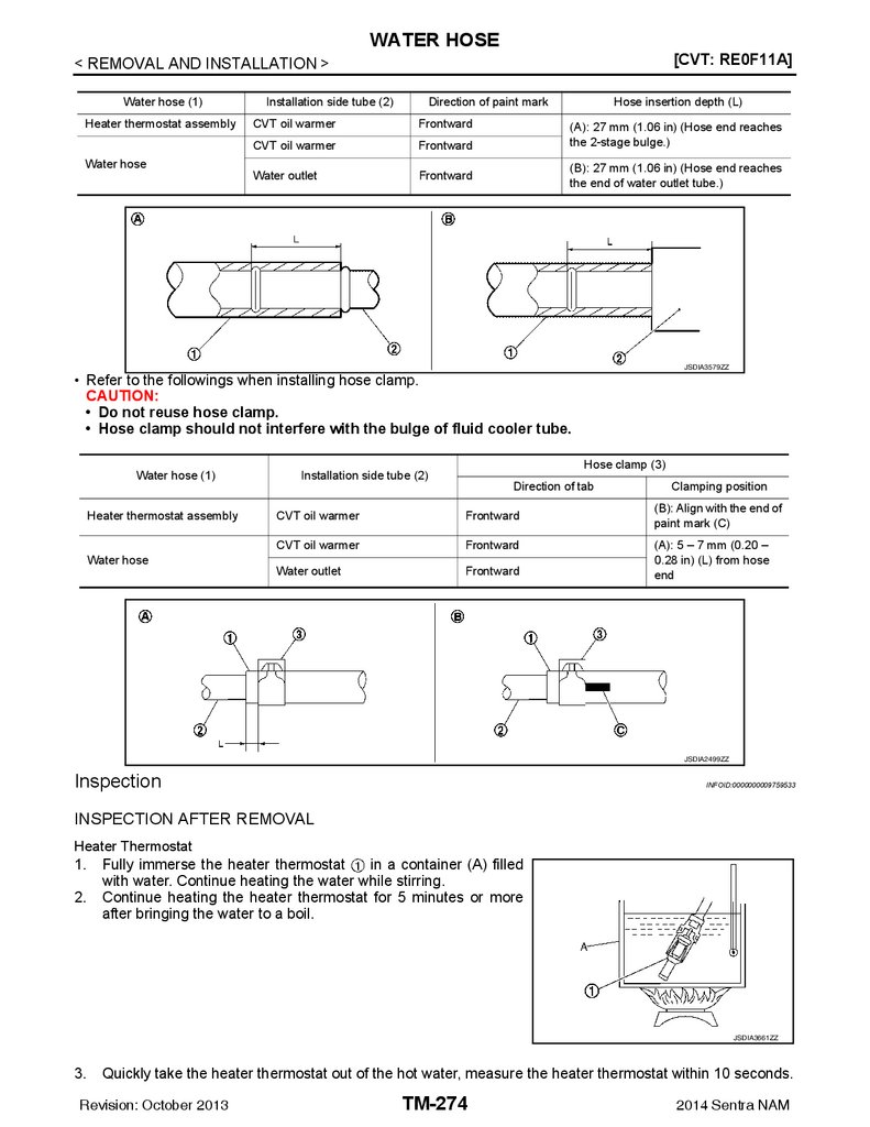
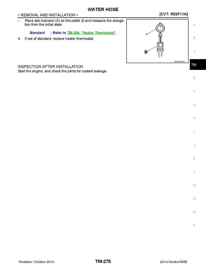
Inspection ..............................................................274
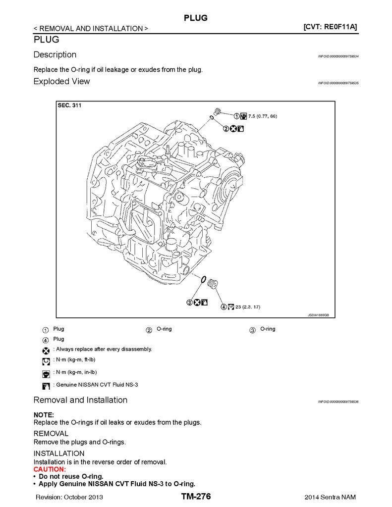
PLUG ............................................................... 276
Description .............................................................276
Exploded View .......................................................276
Removal and Installation .......................................276
Inspection and Adjustment ....................................277
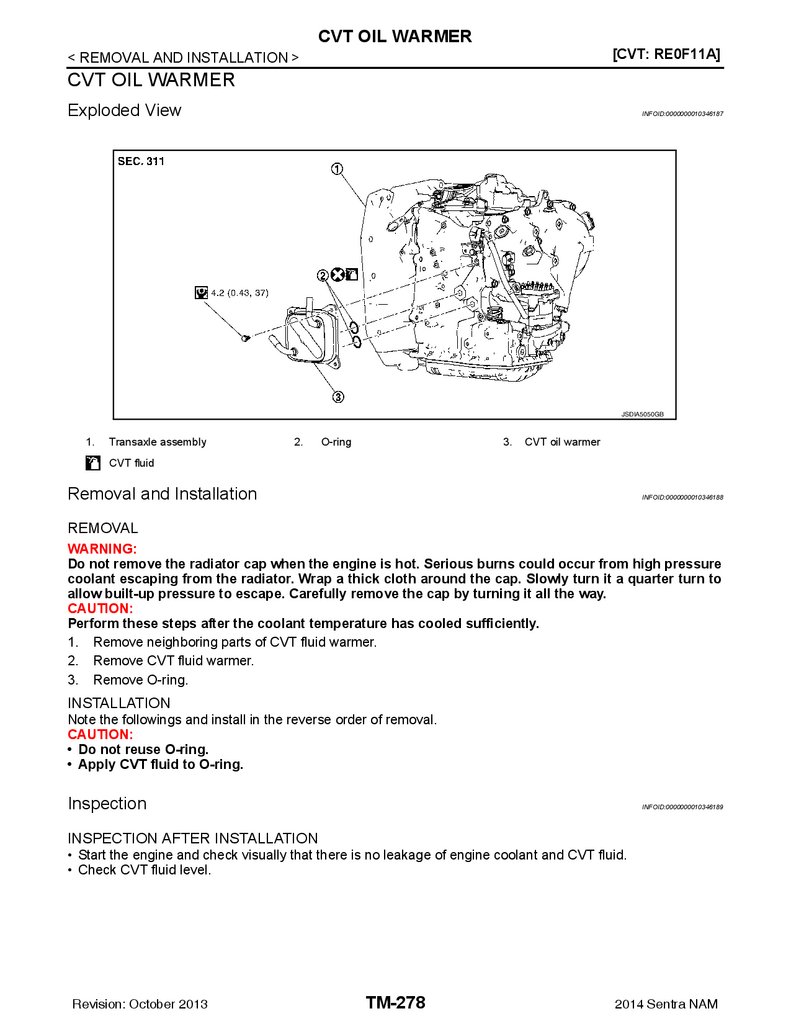
CVT OIL WARMER .......................................... 278
UNIT REMOVAL AND INSTALLATION ... 283
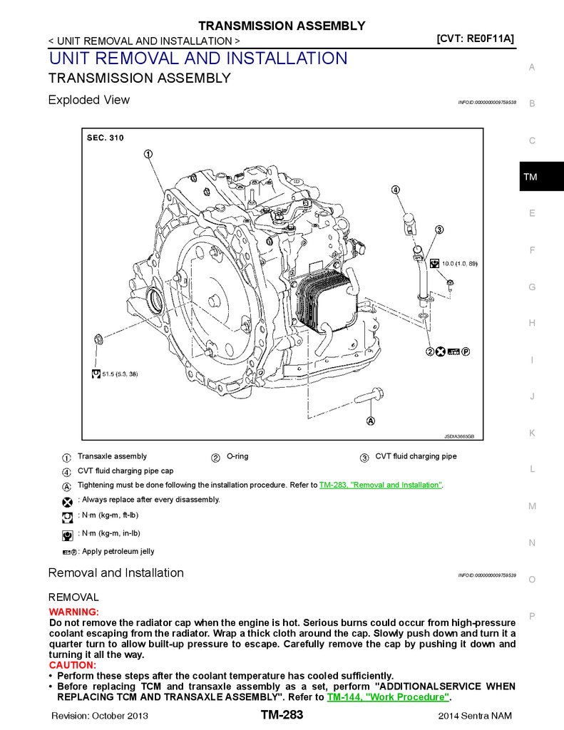
TRANSMISSION ASSEMBLY .......................... 283
Exploded View ...................................................... 283
Removal and Installation ....................................... 283
Inspection and Adjustment .................................... 285
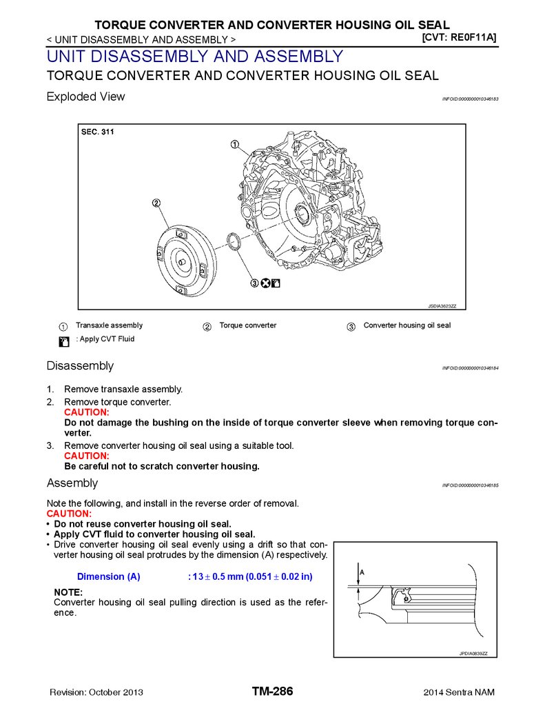
UNIT DISASSEMBLY AND ASSEMBLY .. 286
TORQUE CONVERTER AND CONVERTER
HOUSING OIL SEAL ........................................ 286
Exploded View ...................................................... 286
Disassembly .......................................................... 286
Assembly .............................................................. 286
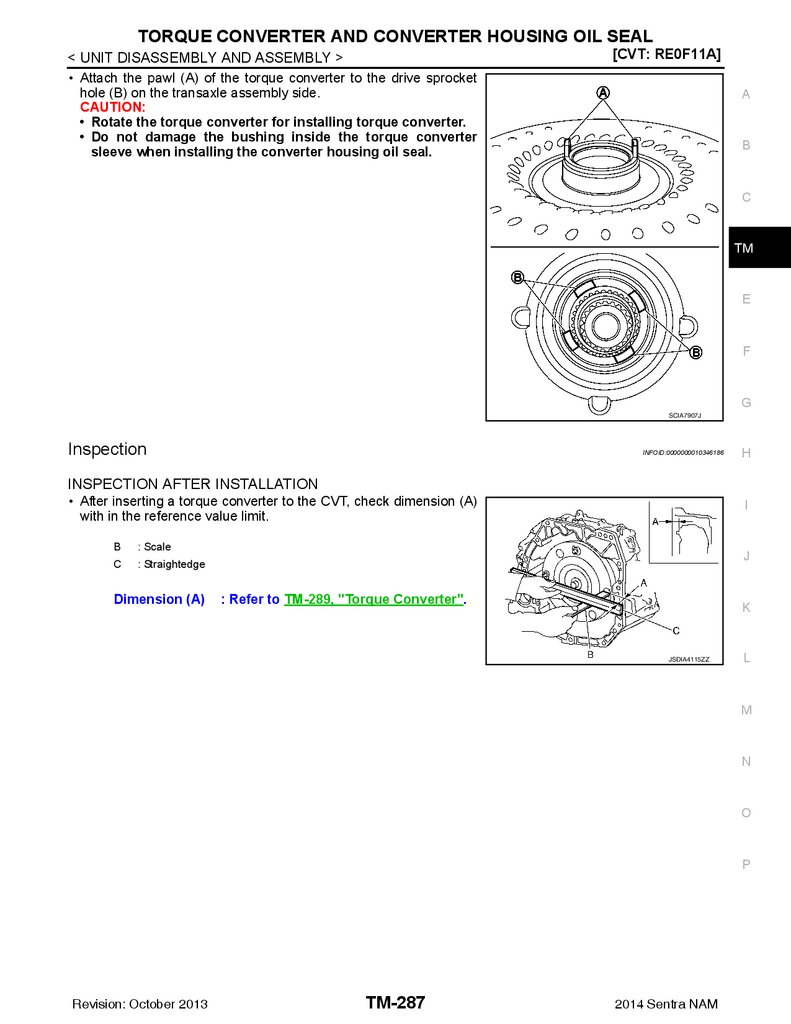
Inspection .............................................................. 287
Exploded View .......................................................278
Removal and Installation .......................................278
Inspection ..............................................................278
SERVICE DATA AND SPECIFICATIONS
(SDS) ......................................................... 288
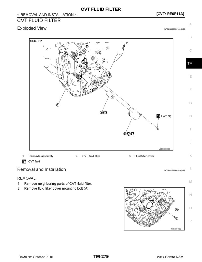
CVT FLUID FILTER ......................................... 279
SERVICE DATA AND SPECIFICATIONS
(SDS) ................................................................ 288
Exploded View .......................................................279
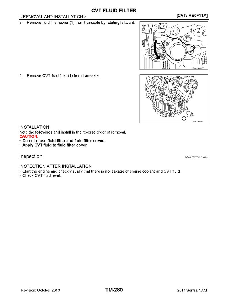
Removal and Installation .......................................279
Inspection ..............................................................280
ELECTRIC OIL PUMP ..................................... 281
Exploded View .......................................................281
Removal and Installation .......................................281
Inspection ..............................................................282
Revision: October 2013
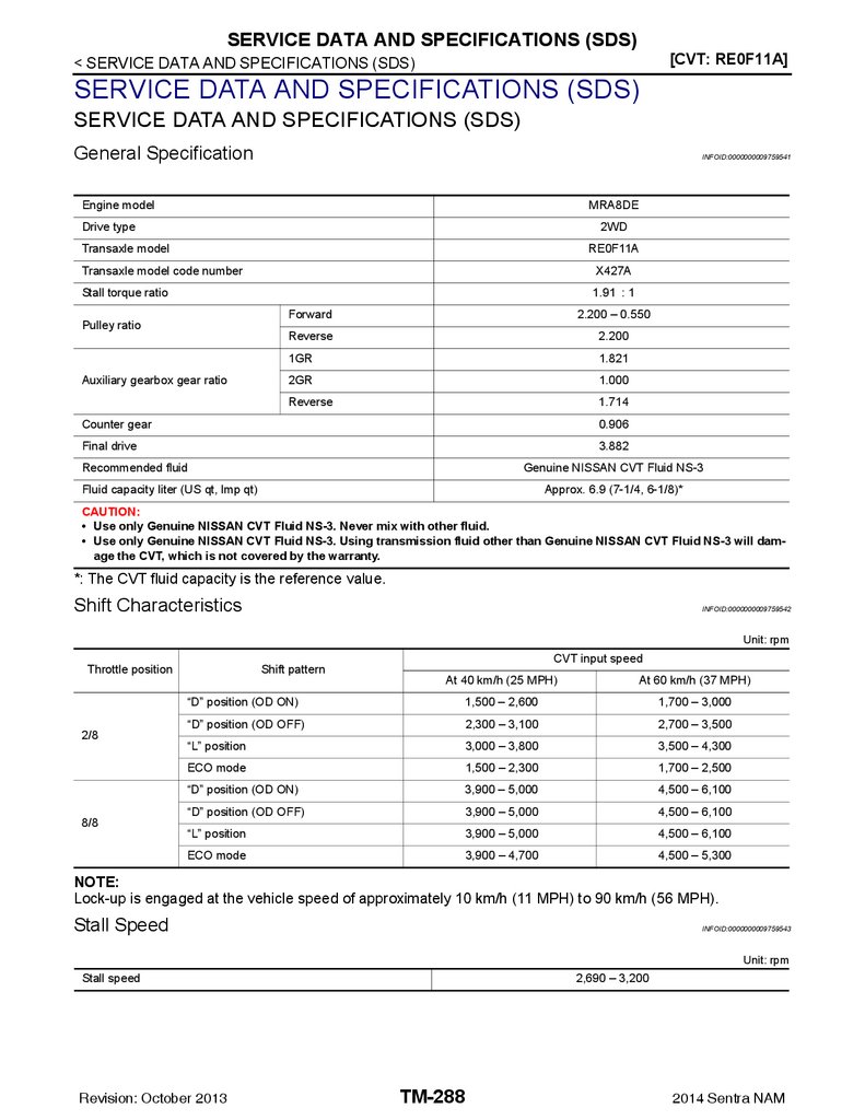
General Specification ............................................ 288
Shift Characteristics .............................................. 288
Stall Speed ............................................................ 288
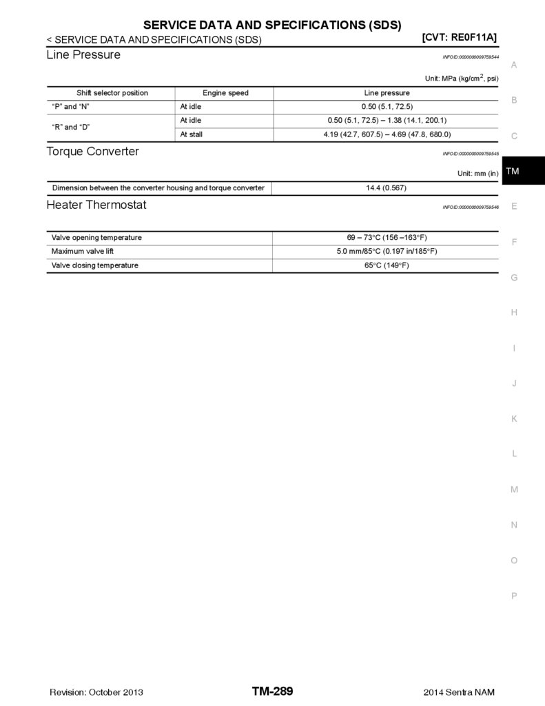
Line Pressure ........................................................ 289
Torque Converter .................................................. 289
Heater Thermostat ................................................ 289
TM-6
2014 Sentra NAM
7.
PRECAUTIONS[6MT: RS6F94R]
< PRECAUTION >
PRECAUTION
A
PRECAUTIONS
Precaution for Supplemental Restraint System (SRS) "AIR BAG" and "SEAT BELT
PRE-TENSIONER"
B
INFOID:0000000010290128
The Supplemental Restraint System such as “AIR BAG” and “SEAT BELT PRE-TENSIONER”, used along C
with a front seat belt, helps to reduce the risk or severity of injury to the driver and front passenger for certain
types of collision. Information necessary to service the system safely is included in the SR and SB section of
this Service Manual.
TM
WARNING:
• To avoid rendering the SRS inoperative, which could increase the risk of personal injury or death in
the event of a collision which would result in air bag inflation, all maintenance must be performed by
an authorized NISSAN/INFINITI dealer.
E
• Improper maintenance, including incorrect removal and installation of the SRS, can lead to personal
injury caused by unintentional activation of the system. For removal of Spiral Cable and Air Bag
Module, see the SR section.
F
• Do not use electrical test equipment on any circuit related to the SRS unless instructed to in this
Service Manual. SRS wiring harnesses can be identified by yellow and/or orange harnesses or harness connectors.
G
PRECAUTIONS WHEN USING POWER TOOLS (AIR OR ELECTRIC) AND HAMMERS
WARNING:
• When working near the Airbag Diagnosis Sensor Unit or other Airbag System sensors with the Ignition ON or engine running, DO NOT use air or electric power tools or strike near the sensor(s) with a
hammer. Heavy vibration could activate the sensor(s) and deploy the air bag(s), possibly causing
serious injury.
• When using air or electric power tools or hammers, always switch the Ignition OFF, disconnect the
battery and wait at least three minutes before performing any service.
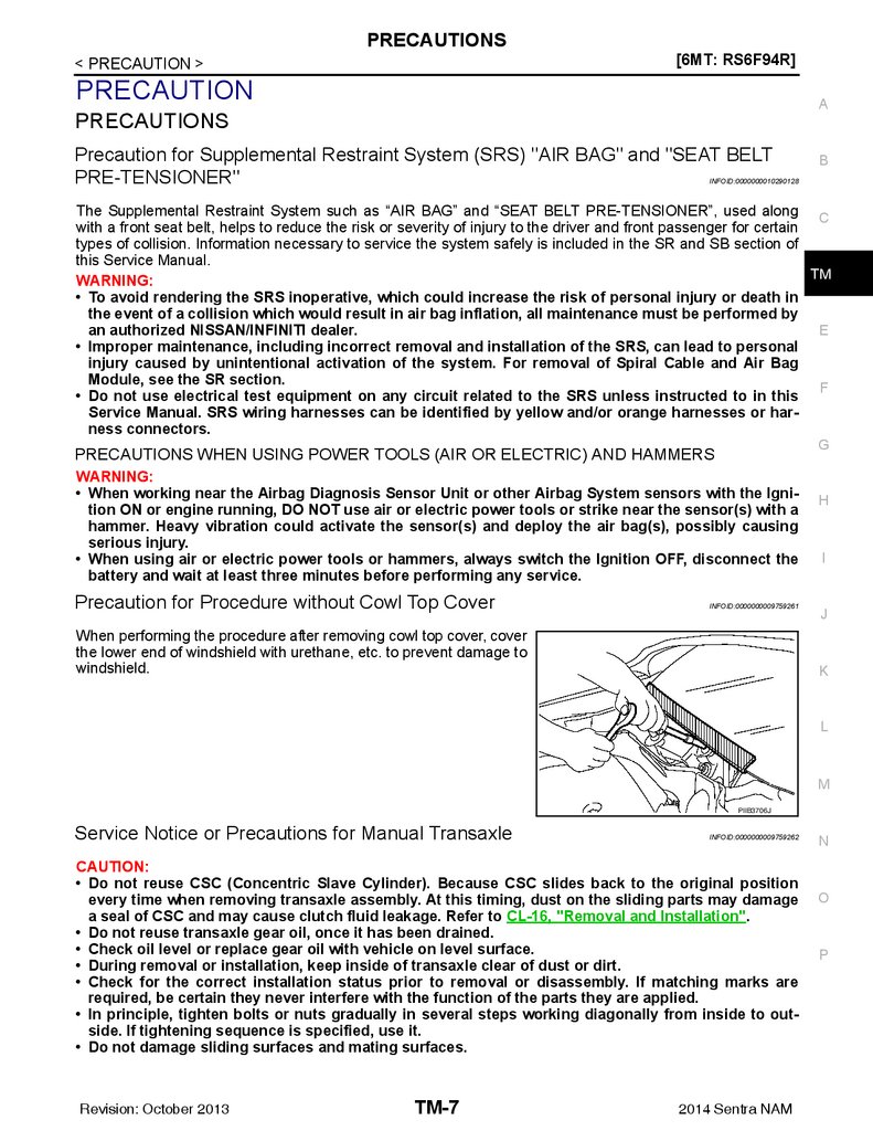
Precaution for Procedure without Cowl Top Cover
INFOID:0000000009759261
When performing the procedure after removing cowl top cover, cover
the lower end of windshield with urethane, etc. to prevent damage to
windshield.
H
I
J
K
L
M
PIIB3706J
Service Notice or Precautions for Manual Transaxle
INFOID:0000000009759262
CAUTION:
• Do not reuse CSC (Concentric Slave Cylinder). Because CSC slides back to the original position
every time when removing transaxle assembly. At this timing, dust on the sliding parts may damage
a seal of CSC and may cause clutch fluid leakage. Refer to CL-16, "Removal and Installation".
• Do not reuse transaxle gear oil, once it has been drained.
• Check oil level or replace gear oil with vehicle on level surface.
• During removal or installation, keep inside of transaxle clear of dust or dirt.
• Check for the correct installation status prior to removal or disassembly. If matching marks are
required, be certain they never interfere with the function of the parts they are applied.
• In principle, tighten bolts or nuts gradually in several steps working diagonally from inside to outside. If tightening sequence is specified, use it.
• Do not damage sliding surfaces and mating surfaces.
Revision: October 2013
TM-7
2014 Sentra NAM
N
O
P
8.
PRECAUTIONS[6MT: RS6F94R]
< PRECAUTION >
Liquid Gasket
INFOID:0000000009759263
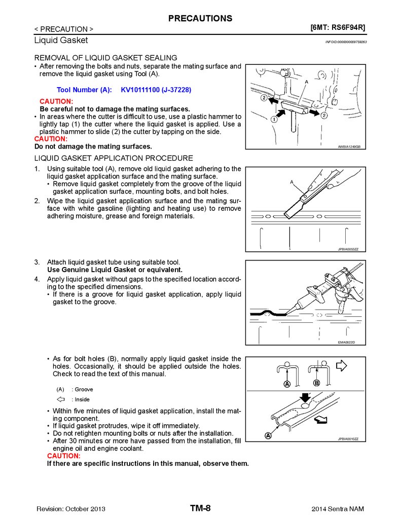
REMOVAL OF LIQUID GASKET SEALING
• After removing the bolts and nuts, separate the mating surface and
remove the liquid gasket using Tool (A).
Tool Number (A):
KV10111100 (J-37228)
CAUTION:
Be careful not to damage the mating surfaces.
• In areas where the cutter is difficult to use, use a plastic hammer to
lightly tap (1) the cutter where the liquid gasket is applied. Use a
plastic hammer to slide (2) the cutter by tapping on the side.
CAUTION:
Do not damage the mating surfaces.
AWBIA1249GB
LIQUID GASKET APPLICATION PROCEDURE
1.
2.
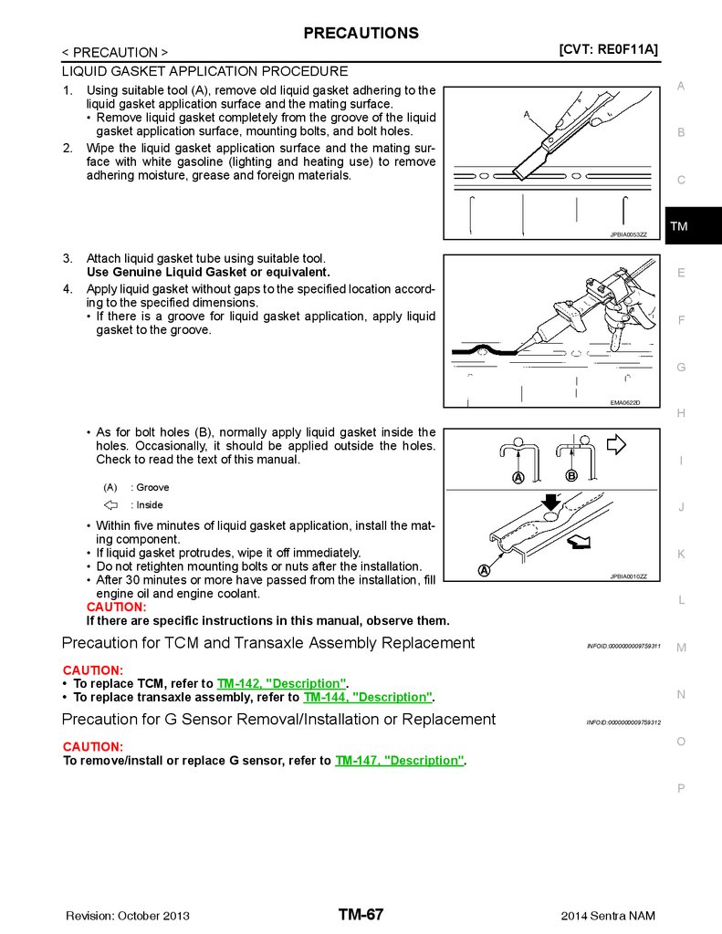
Using suitable tool (A), remove old liquid gasket adhering to the
liquid gasket application surface and the mating surface.
• Remove liquid gasket completely from the groove of the liquid
gasket application surface, mounting bolts, and bolt holes.
Wipe the liquid gasket application surface and the mating surface with white gasoline (lighting and heating use) to remove
adhering moisture, grease and foreign materials.
JPBIA0053ZZ
3.
4.
Attach liquid gasket tube using suitable tool.
Use Genuine Liquid Gasket or equivalent.
Apply liquid gasket without gaps to the specified location according to the specified dimensions.
• If there is a groove for liquid gasket application, apply liquid
gasket to the groove.
EMA0622D
• As for bolt holes (B), normally apply liquid gasket inside the
holes. Occasionally, it should be applied outside the holes.
Check to read the text of this manual.
(A)
: Groove
: Inside
• Within five minutes of liquid gasket application, install the mating component.
• If liquid gasket protrudes, wipe it off immediately.
• Do not retighten mounting bolts or nuts after the installation.
• After 30 minutes or more have passed from the installation, fill
engine oil and engine coolant.
CAUTION:
If there are specific instructions in this manual, observe them.
Revision: October 2013
TM-8
JPBIA0010ZZ
2014 Sentra NAM
9.
PREPARATION[6MT: RS6F94R]
< PREPARATION >
PREPARATION
A
PREPARATION
Special Service Tools
INFOID:0000000009759264
B
The actual shape of the tools may differ from those illustrated here.
Tool number
(TechMate No.)
Tool name
Description
KV381054S0
(J-34286)
Puller
Removing mainshaft front bearing outer race
C
TM
E
ZZA0601D
KV38100200
(
—
)
Drift
• Installing mainshaft front bearing outer race
• Installing mainshaft rear bearing outer race
• Installing differential side bearing outer race
(clutch housing side)
a: 65 mm (2.56 in) dia.
b: 49 mm (1.93 in) dia.
G
H
ZZA1143D
ST33220000
(
—
)
Drift
F
Installing input shaft oil seal
a: 37 mm (1.46 in) dia.
b: 31 mm (1.22 in) dia.
c: 22mm (0.87in) dia.
I
J
ZZA1046D
ST33400001
(J-26082)
Drift
Installing differential side bearing outer race
(transaxle case side)
a: 60 mm (2.36 in) dia.
b: 47 mm (1.85 in) dia.
K
L
M
ZZA0814D
KV32500QAA
(
—
)
(Renault SST: B.vi 1666)
Drift set
JPDIC0730ZZ
Revision: October 2013
TM-9
Installing differential side oil seal
1.
—
(Stamping number: B.vi 1666-A)
Drift
a: 54.3 mm (2.138 in) dia.
b: 45 mm (1.77 in) dia.
c: 26.6 mm (1.047 in) dia.
2.
—
(Stamping number: B.vi 1666-B)
Drift
d: 54 mm (2.13 in) dia.
e: 48.6 mm (1.913 in) dia.
f: 26.6 mm (1.047 in) dia.
2014 Sentra NAM
N
O
P
10.
PREPARATION[6MT: RS6F94R]
< PREPARATION >
Tool number
(TechMate No.)
Tool name
Description
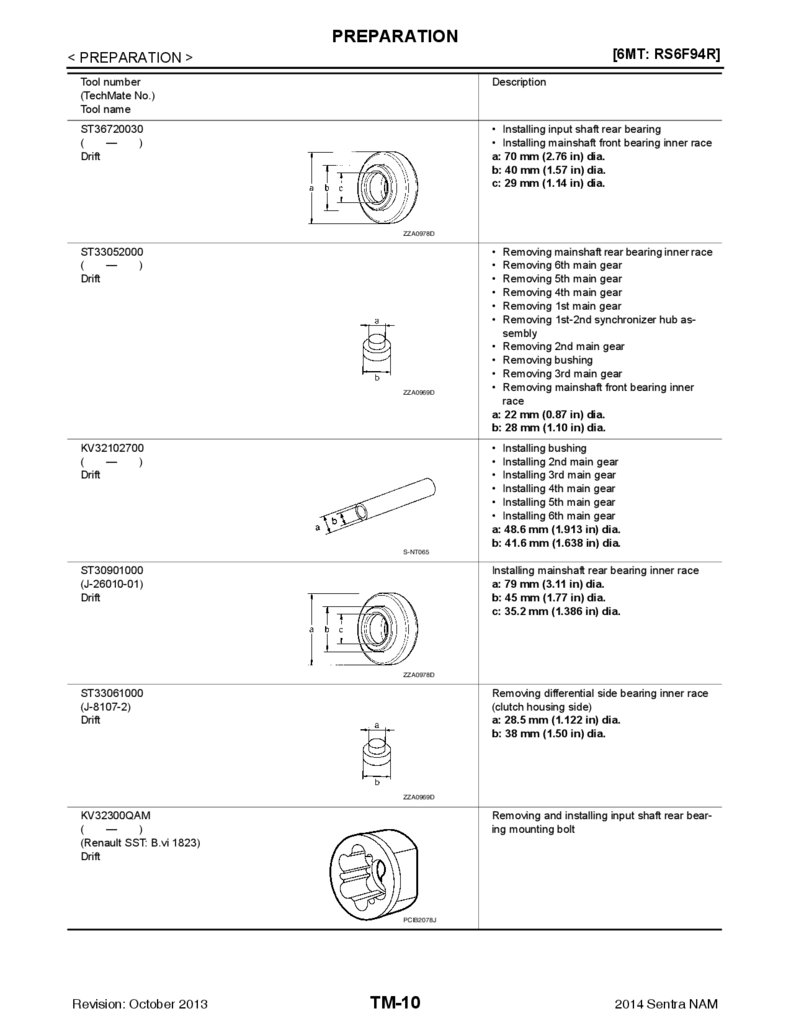
ST36720030
(
—
)
Drift
• Installing input shaft rear bearing
• Installing mainshaft front bearing inner race
a: 70 mm (2.76 in) dia.
b: 40 mm (1.57 in) dia.
c: 29 mm (1.14 in) dia.
ZZA0978D
ST33052000
(
—
)
Drift
ZZA0969D
KV32102700
(
—
)
Drift
Removing mainshaft rear bearing inner race
Removing 6th main gear
Removing 5th main gear
Removing 4th main gear
Removing 1st main gear
Removing 1st-2nd synchronizer hub assembly
• Removing 2nd main gear
• Removing bushing
• Removing 3rd main gear
• Removing mainshaft front bearing inner
race
a: 22 mm (0.87 in) dia.
b: 28 mm (1.10 in) dia.
• Installing bushing
• Installing 2nd main gear
• Installing 3rd main gear
• Installing 4th main gear
• Installing 5th main gear
• Installing 6th main gear
a: 48.6 mm (1.913 in) dia.
b: 41.6 mm (1.638 in) dia.
S-NT065
ST30901000
(J-26010-01)
Drift
Installing mainshaft rear bearing inner race
a: 79 mm (3.11 in) dia.
b: 45 mm (1.77 in) dia.
c: 35.2 mm (1.386 in) dia.
ZZA0978D
ST33061000
(J-8107-2)
Drift
Removing differential side bearing inner race
(clutch housing side)
a: 28.5 mm (1.122 in) dia.
b: 38 mm (1.50 in) dia.
ZZA0969D
Removing and installing input shaft rear bearing mounting bolt
KV32300QAM
(
—
)
(Renault SST: B.vi 1823)
Drift
PCIB2078J
Revision: October 2013
TM-10
2014 Sentra NAM
11.
PREPARATION[6MT: RS6F94R]
< PREPARATION >
Commercial Service Tools
INFOID:0000000009759265
A
Tool name
Description
Socket
Removing and installing drain plug
a: 8 mm (0.31 in)
b: 5 mm (0.20 in)
B
C
TM
PCIB1776E
Spacer
Removing mainshaft front bearing outer race
a: 25 mm (0.98 in) dia.
b: 25 mm (0.98 in)
E
F
PCIB1780E
Drift
Installing bushing
a: 17 mm (0.67 in) dia.
G
H
S-NT063
Drift
Removing input shaft rear bearing
a: 24 mm (0.94 in) dia.
I
J
K
PCIB1779E
Drift
Installing input shaft front bearing
a: 35 mm (1.38 in) dia.
b: 25 mm (0.98 in) dia.
L
M
S-NT065
Drift
• Installing input shaft rear bearing
• Removing differential side bearing inner
race (transaxle case side)
a: 43 mm (1.69 in) dia.
TM-11
O
P
NT109
Revision: October 2013
N
2014 Sentra NAM
12.
PREPARATION[6MT: RS6F94R]
< PREPARATION >
Tool name
Description
Drift
Installing differential side bearing inner race
(clutch housing side)
a: 45 mm (1.77 in) dia.
b: 39 mm (1.54 in) dia.
S-NT474
Drift
Installing differential side bearing inner race
(transaxle case side)
a: 52 mm (2.05 in) dia.
b: 45 mm (1.77 in) dia.
S-NT474
Puller
• Removing differential side bearing inner
race (clutch housing side)
• Removing differential side bearing inner
race (transaxle case side)
NT077
Puller
ZZB0823D
Remover
• Removing differential side bearing inner
race (clutch housing side)
• Removing differential side bearing inner
race (transaxle case side)
• Removing input shaft rear bearing
• Removing input shaft front bearing
• Removing mainshaft rear bearing inner race
• Removing 6th main gear
• Removing 4th main gear
• Removing 5th main gear
• Removing 1st main gear
• Removing 1st-2nd synchronizer hub assembly
• Removing 2nd main gear
• Removing 3rd main gear
• Removing mainshaft front bearing inner
race
• Removing bushing
• Removing mainshaft rear bearing outer
race
S-NT134
Revision: October 2013
TM-12
2014 Sentra NAM
13.
PREPARATION[6MT: RS6F94R]
< PREPARATION >
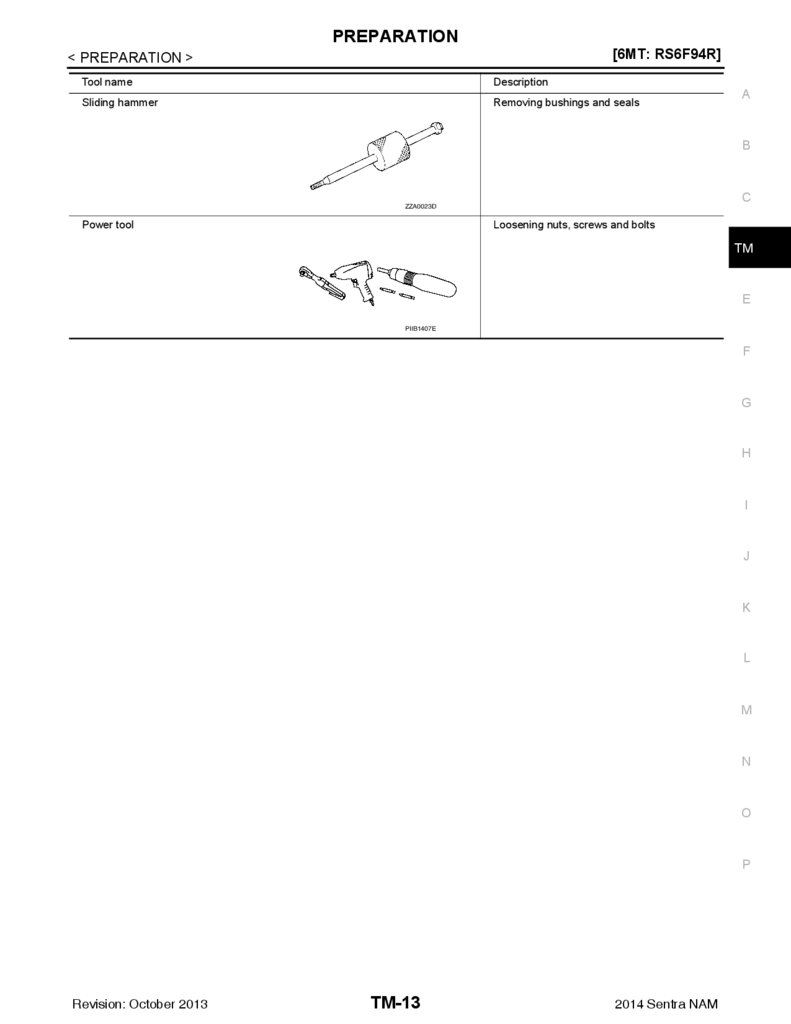
Tool name
Description
Sliding hammer
Removing bushings and seals
A
B
C
ZZA0023D
Power tool
Loosening nuts, screws and bolts
TM
E
PIIB1407E
F
G
H
I
J
K
L
M
N
O
P
Revision: October 2013
TM-13
2014 Sentra NAM
14.
COMPONENT PARTS[6MT: RS6F94R]
< SYSTEM DESCRIPTION >
SYSTEM DESCRIPTION
COMPONENT PARTS
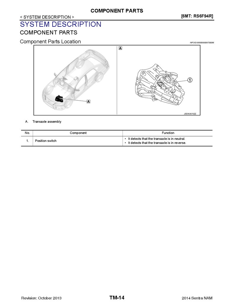
Component Parts Location
INFOID:0000000009759266
JSDIA3670ZZ
A.
Transaxle assembly
No.
1.
Component
Function
• It detects that the transaxle is in neutral.
• It detects that the transaxle is in reverse.
Position switch
Revision: October 2013
TM-14
2014 Sentra NAM
15.
STRUCTURE AND OPERATION[6MT: RS6F94R]
< SYSTEM DESCRIPTION >
STRUCTURE AND OPERATION
A
Sectional View
INFOID:0000000009759267
B
C
TM
E
F
G
H
I
J
K
L
M
JPDIC0631ZZ
N
1.
3rd input gear
2.
3rd-4th synchronizer hub assembly
3.
4th input gear
4.
5th input gear
5.
5th-6th synchronizer hub assembly
6.
6th input gear
7.
Transaxle case
8.
6th main gear
9.
5th main gear
10.
4th main gear
11.
3rd main gear
12.
2nd main gear
13.
1st-2nd synchronizer hub assembly
14.
1st main gear
15.
Differential
16.
Final gear
17.
Mainshaft
18.
Input shaft
19.
Clutch housing
20.
Reverse idler shaft
21.
Reverse input gear
22.
Reverse output gear
System Description
O
P
INFOID:0000000009759268
TRIPLE-CONE SYNCHRONIZER
Revision: October 2013
TM-15
2014 Sentra NAM
16.
STRUCTURE AND OPERATION< SYSTEM DESCRIPTION >
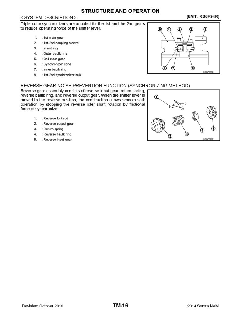
Triple-cone synchronizers are adopted for the 1st and the 2nd gears
to reduce operating force of the shifter lever.
1.
: 1st main gear
2.
: 1st-2nd coupling sleeve
3.
: Insert key
4.
: Outer baulk ring
5.
: 2nd main gear
6.
: Synchronizer cone
7.
: Inner baulk ring
8.
: 1st-2nd synchronizer hub
[6MT: RS6F94R]
SCIA7636E
REVERSE GEAR NOISE PREVENTION FUNCTION (SYNCHRONIZING METHOD)
Reverse gear assembly consists of reverse input gear, return spring,
reverse baulk ring, and reverse output gear. When the shifter lever is
moved to the reverse position, the construction allows smooth shift
operation by stopping the reverse idler shaft rotation by frictional
force of synchronizer.
1.
: Reverse fork rod
2.
: Reverse output gear
3.
: Return spring
4.
: Reverse baulk ring
5.
: Reverse input gear
Revision: October 2013
SCIA7621E
TM-16
2014 Sentra NAM
17.
POSITION SWITCH[6MT: RS6F94R]
< DTC/CIRCUIT DIAGNOSIS >
DTC/CIRCUIT DIAGNOSIS
A
POSITION SWITCH
BACK-UP LAMP SWITCH
B
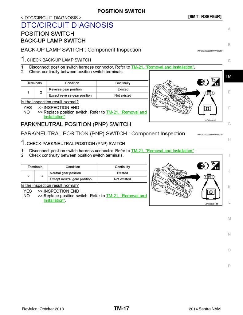
BACK-UP LAMP SWITCH : Component Inspection
INFOID:0000000009759269
1.CHECK BACK-UP LAMP SWITCH
1.
2.
C
Disconnect position switch harness connector. Refer to TM-21, "Removal and Installation".
Check continuity between position switch terminals.
TM
Terminals
1
2
Condition
Reverse gear position
Except reverse gear position
Continuity
Existed
E
Not existed
Is the inspection result normal?
YES >> INSPECTION END
NO
>> Replace position switch. Refer to TM-21, "Removal and
Installation".
F
PCIB1781E
PARK/NEUTRAL POSITION (PNP) SWITCH
G
PARK/NEUTRAL POSITION (PNP) SWITCH : Component Inspection
INFOID:0000000009759270
H
1.CHECK PARK/NEUTRAL POSITION (PNP) SWITCH
1.
2.
Disconnect position switch harness connector. Refer to TM-21, "Removal and Installation".
Check continuity between position switch terminals.
Terminals
2
3
Condition
Neutral gear position
Except neutral gear position
I
Continuity
J
Existed
Not existed
Is the inspection result normal?
YES >> INSPECTION END
NO
>> Replace position switch. Refer to TM-21, "Removal and
Installation".
K
JPDIC0091ZZ
L
M
N
O
P
Revision: October 2013
TM-17
2014 Sentra NAM
18.
NOISE, VIBRATION AND HARSHNESS (NVH) TROUBLESHOOTING[6MT: RS6F94R]
< SYMPTOM DIAGNOSIS >
SYMPTOM DIAGNOSIS
NOISE, VIBRATION AND HARSHNESS (NVH) TROUBLESHOOTING
NVH Troubleshooting Chart
INFOID:0000000009759271
1
Hard to shift or will not shift
1
1
Jumps out of gear
2
2
SHIFT FORK (Worn)
TM-30, "Exploded View"
3
TM-30, "Exploded View"
SHIFT CONTROL LINKAGE (Worn)
3
2
2
1
TM-18
3
INSERT SPRING (Damaged)
3
3
BAULK RING (Worn or damaged)
Oil leaks
Revision: October 2013
TM-26, "Inspection"
2
BEARING (Worn or damaged)
1
GEAR (Worn or damaged)
Noise
O-RING (Worn or damaged)
GASKET (Damaged)
OIL (Oil level is high)
TM-30, "Exploded View"
Reference
Symptoms
OIL (Wrong oil)
TM-19, "Inspection"
OIL (Oil level is low)
SUSPECTED PARTS
(Possible cause)
OIL SEAL (Worn or damaged)
Use the chart below to find the cause of the symptom. The numbers indicate the order of the inspection. If necessary, repair or replace these parts.
2
2
2014 Sentra NAM
19.
M/T OIL[6MT: RS6F94R]
< PERIODIC MAINTENANCE >
PERIODIC MAINTENANCE
A
M/T OIL
Inspection
INFOID:0000000009759272
B
OIL LEAKAGE
Make sure that gear oil is not leaking from transaxle or around it.
C
OIL LEVEL
1.
2.
3.
4.
Remove filler plug (1) and gasket from transaxle case.
Check the oil level from filler plug mounting hole as shown.
CAUTION:
Do not start engine while checking oil level.
Set a gasket on filler plug and then install it to transaxle case.
CAUTION:
Do not reuse gasket.
Tighten filler plug to the specified torque. Refer to TM-30,
"Exploded View".
CAUTION:
Do not overtighten the filler plug as this could cause the
transaxle case to crack.
Draining
TM
E
F
SCIA7623E
G
INFOID:0000000009759273
H
1.
2.
3.
4.
Start engine and let it run to warm up transaxle.
Stop engine. Remove drain plug (1) and gasket, using a suitable
tool and then drain gear oil.
Set a gasket on drain plug and install it to clutch housing, using
a suitable tool.
CAUTION:
Do not reuse gasket.
Tighten drain plug to the specified torque. Refer to TM-30,
"Exploded View".
CAUTION:
Do not overtighten the filler plug as this could cause the
transaxle case to crack.
Refilling
1.
2.
4.
5.
J
K
SCIA7622E
L
INFOID:0000000009759274
Remove filler plug (1) and gasket from transaxle case.
Fill with new gear oil until oil level reaches the specified limit at
filler plug mounting hole as shown.
Oil grade and
viscosity
Oil capacity
3.
I
N
: Refer to MA-11, "Fluids and Lubricants".
: Refer to MA-11, "Fluids and Lubricants".
After refilling gear oil, check the oil level. Refer to TM-19,
"Inspection".
Set a gasket on filler plug and then install it to transaxle case.
CAUTION:
Do not reuse gasket.
Tighten filler plug to the specified torque. Refer to TM-30, "Exploded View".
CAUTION:
Do not overtighten the filler plug as this could cause the transaxle case to crack.
Revision: October 2013
M
TM-19
O
SCIA7623E
2014 Sentra NAM
P
20.
SIDE OIL SEAL[6MT: RS6F94R]
< REMOVAL AND INSTALLATION >
REMOVAL AND INSTALLATION
SIDE OIL SEAL
Removal and Installation
INFOID:0000000009759275
REMOVAL
1.
2.
Remove front drive shafts. Refer to FAX-18, "6M/T : Removal and Installation (LH)".
Remove differential side oil seals (1) from clutch housing and
transaxle case using a suitable tool.
CAUTION:
Do not damage transaxle case and clutch housing.
SCIA7625E
INSTALLATION
Installation is in the reverse order of removal.
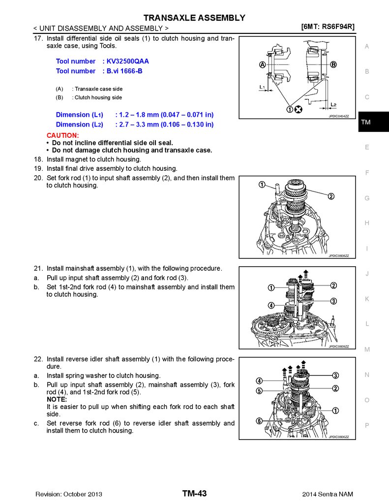
• Install differential side oil seals (1) to clutch housing and transaxle case, using Tools.
Tool number
Tool number
: KV32500QAA
: B.vi 1666-B
(A)
: Transaxle case side
(B)
: Clutch housing side
Dimension (L1)
Dimension (L2)
: 1.2 – 1.8 mm (0.047 – 0.071 in)
: 2.7 – 3.3 mm (0.106 – 0.130 in)
CAUTION:
• Do not incline differential side oil seal.
• Do not damage clutch housing and transaxle case.
Inspection
JPDIC0454ZZ
INFOID:0000000009759276
INSPECTION AFTER INSTALLATION
Check the oil level and oil leaks. Refer to TM-19, "Inspection".
Revision: October 2013
TM-20
2014 Sentra NAM
21.
POSITION SWITCH[6MT: RS6F94R]
< REMOVAL AND INSTALLATION >
POSITION SWITCH
A
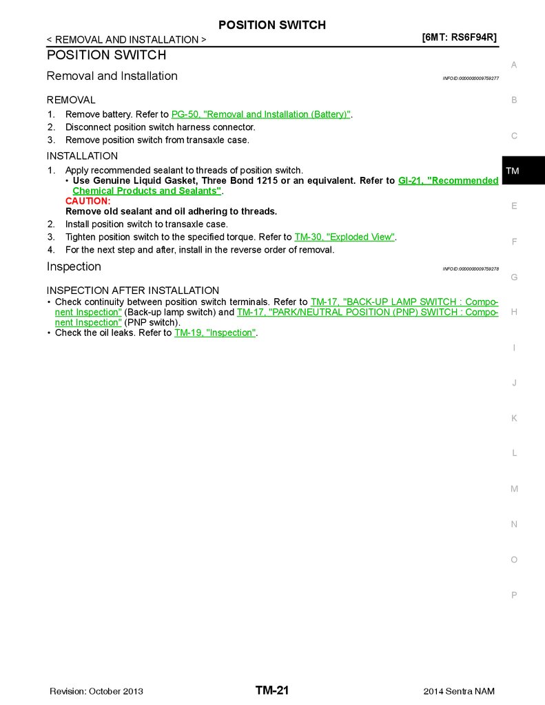
Removal and Installation
INFOID:0000000009759277
REMOVAL
1.
2.
3.
B
Remove battery. Refer to PG-50, "Removal and Installation (Battery)".
Disconnect position switch harness connector.
Remove position switch from transaxle case.
C
INSTALLATION
1.
2.
3.
4.
Apply recommended sealant to threads of position switch.
TM
• Use Genuine Liquid Gasket, Three Bond 1215 or an equivalent. Refer to GI-21, "Recommended
Chemical Products and Sealants".
CAUTION:
E
Remove old sealant and oil adhering to threads.
Install position switch to transaxle case.
Tighten position switch to the specified torque. Refer to TM-30, "Exploded View".
F
For the next step and after, install in the reverse order of removal.
Inspection
INFOID:0000000009759278
G
INSPECTION AFTER INSTALLATION
• Check continuity between position switch terminals. Refer to TM-17, "BACK-UP LAMP SWITCH : Component Inspection" (Back-up lamp switch) and TM-17, "PARK/NEUTRAL POSITION (PNP) SWITCH : Component Inspection" (PNP switch).
• Check the oil leaks. Refer to TM-19, "Inspection".
H
I
J
K
L
M
N
O
P
Revision: October 2013
TM-21
2014 Sentra NAM
22.
CONTROL LINKAGE[6MT: RS6F94R]
< REMOVAL AND INSTALLATION >
CONTROL LINKAGE
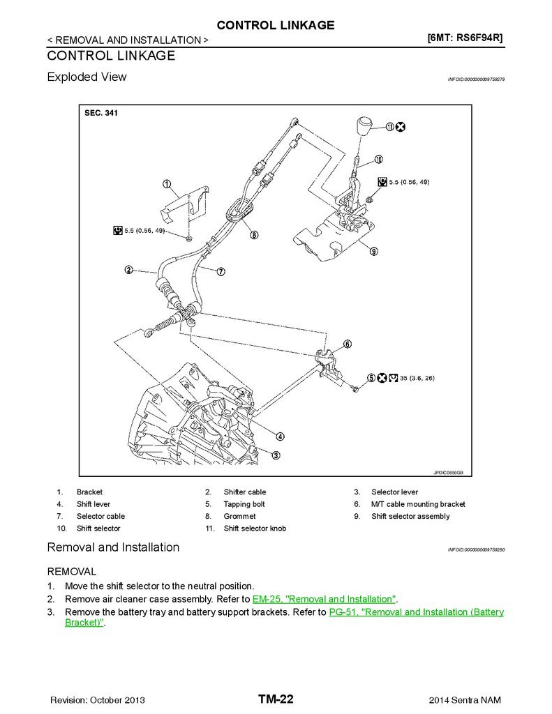
Exploded View
INFOID:0000000009759279
JPDIC0856GB
1.
Bracket
2.
Shifter cable
3.
Selector lever
4.
Shift lever
5.
Tapping bolt
6.
M/T cable mounting bracket
7.
Selector cable
8.
Grommet
9.
Shift selector assembly
10.
Shift selector
11.
Shift selector knob
Removal and Installation
INFOID:0000000009759280
REMOVAL
1.
2.
3.
Move the shift selector to the neutral position.
Remove air cleaner case assembly. Refer to EM-25, "Removal and Installation".
Remove the battery tray and battery support brackets. Refer to PG-51, "Removal and Installation (Battery
Bracket)".
Revision: October 2013
TM-22
2014 Sentra NAM
23.
CONTROL LINKAGE< REMOVAL AND INSTALLATION >
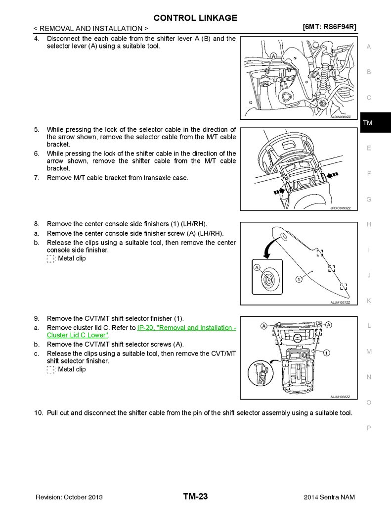
4. Disconnect the each cable from the shifter lever A (B) and the
selector lever (A) using a suitable tool.
[6MT: RS6F94R]
A
B
C
ALDIA0380ZZ
5.
6.
7.
TM
While pressing the lock of the selector cable in the direction of
the arrow shown, remove the selector cable from the M/T cable
bracket.
While pressing the lock of the shifter cable in the direction of the
arrow shown, remove the shifter cable from the M/T cable
bracket.
Remove M/T cable bracket from transaxle case.
E
F
G
JPDIC0793ZZ
8.
a.
b.
Remove the center console side finishers (1) (LH/RH).
Remove the center console side finisher screw (A) (LH/RH).
Release the clips using a suitable tool, then remove the center
console side finisher.
: Metal clip
H
I
J
ALJIA1037ZZ
9.
a.
b.
c.
Remove the CVT/MT shift selector finisher (1).
Remove cluster lid C. Refer to IP-20, "Removal and Installation Cluster Lid C Lower".
Remove the CVT/MT shift selector screws (A).
Release the clips using a suitable tool, then remove the CVT/MT
shift selector finisher.
: Metal clip
K
L
M
N
ALJIA1038ZZ
O
10. Pull out and disconnect the shifter cable from the pin of the shift selector assembly using a suitable tool.
P
Revision: October 2013
TM-23
2014 Sentra NAM
24.
CONTROL LINKAGE< REMOVAL AND INSTALLATION >
11. Pull up the cable stopper (A) of the selector cable in the direction
of the arrow as shown.
12. Pull out and disconnect the selector cable from the pin of the
shift selector assembly, using a suitable tool.
[6MT: RS6F94R]
JPDIC0833ZZ
13. While pressing the lock of the selector cable in the direction of
the arrow shown, remove the selector cable from the shift selector assembly.
14. While pressing the lock of the shifter cable in the direction of the
arrow shown, remove the shifter cable from the shift selector
assembly.
15. Remove the shift selector assembly.
JPDIC0793ZZ
16. Remove the tunnel stay (1).
: Front
JSDIA3657ZZ
17. Remove exhaust front tube and sub muffler. Refer to EX-5, "Removal and Installation".
18. Remove the heat plate fixtures (A).
: Front
19. Remove the shift cable and selector cable from the bracket.
AWDIA1074ZZ
Revision: October 2013
TM-24
2014 Sentra NAM
25.
CONTROL LINKAGE< REMOVAL AND INSTALLATION >
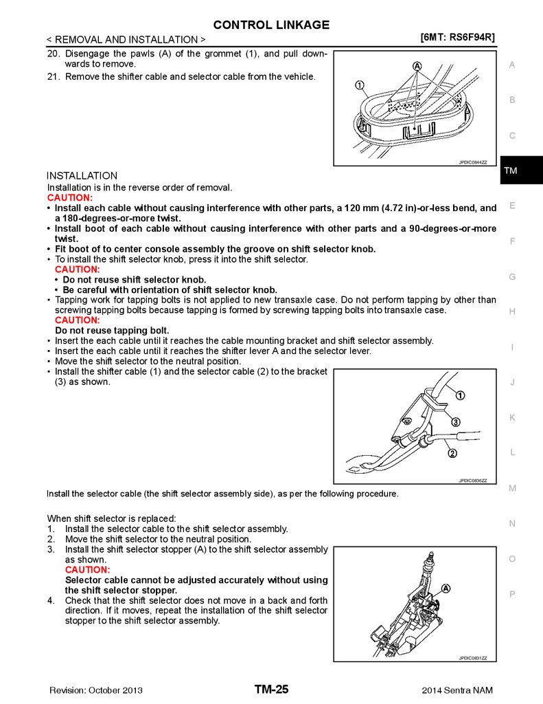
20. Disengage the pawls (A) of the grommet (1), and pull downwards to remove.
21. Remove the shifter cable and selector cable from the vehicle.
[6MT: RS6F94R]
A
B
C
JPDIC0844ZZ
TM
INSTALLATION
Installation is in the reverse order of removal.
CAUTION:
• Install each cable without causing interference with other parts, a 120 mm (4.72 in)-or-less bend, and
a 180-degrees-or-more twist.
• Install boot of each cable without causing interference with other parts and a 90-degrees-or-more
twist.
• Fit boot of to center console assembly the groove on shift selector knob.
• To install the shift selector knob, press it into the shift selector.
CAUTION:
• Do not reuse shift selector knob.
• Be careful with orientation of shift selector knob.
• Tapping work for tapping bolts is not applied to new transaxle case. Do not perform tapping by other than
screwing tapping bolts because tapping is formed by screwing tapping bolts into transaxle case.
CAUTION:
Do not reuse tapping bolt.
• Insert the each cable until it reaches the cable mounting bracket and shift selector assembly.
• Insert the each cable until it reaches the shifter lever A and the selector lever.
• Move the shift selector to the neutral position.
• Install the shifter cable (1) and the selector cable (2) to the bracket
(3) as shown.
E
F
G
H
I
J
K
L
JPDIC0836ZZ
M
Install the selector cable (the shift selector assembly side), as per the following procedure.
When shift selector is replaced:
1. Install the selector cable to the shift selector assembly.
2. Move the shift selector to the neutral position.
3. Install the shift selector stopper (A) to the shift selector assembly
as shown.
CAUTION:
Selector cable cannot be adjusted accurately without using
the shift selector stopper.
4. Check that the shift selector does not move in a back and forth
direction. If it moves, repeat the installation of the shift selector
stopper to the shift selector assembly.
N
O
P
JPDIC0831ZZ
Revision: October 2013
TM-25
2014 Sentra NAM
26.
CONTROL LINKAGE< REMOVAL AND INSTALLATION >
5. Insert the cable stopper (A) until it reaches the selector cable.
6. Remove the shift selector stopper from the shift selector assembly.
7. Move the shift selector to each gear position to check that there
are no bindings. If any, repeat the installation of the shift selector
stopper to the shift selector assembly.
[6MT: RS6F94R]
JPDIC0832ZZ
When shift selector assembly is not replaced:
1. Install the selector cable to the shift selector assembly.
2. Move the shift selector to the 4th gear position.
3. Adjust the length (L) between the cable stopper (A) and the shift
selector to the standard value.
Length (L)
: 3.51 – 4.11 mm (0.1382 – 0.1618 in)
JPDIC0834ZZ
4.
5.
Insert the stopper (A) until it reaches the selector cable.
Move the shift selector to each gear position to check that there
are no bindings. If any, repeat the adjustment of the length
between the cable stopper and the shift selector.
JPDIC0832ZZ
Inspection
INFOID:0000000009759281
INSPECTION AFTER INSTALLATION
Shift selector Knob
Check that the shift selector knob is installed in the right position.
Shifter Cable and Selector Cable
• Pull each cable in the removal direction to check that it dose not disconnect from the cable mounting
bracket.
• Pull each cable in the removal direction to check that it dose not disconnect from the shift selector assembly.
• Pull grommet in the removal direction to check that it dose not disconnect from the vehicle.
Shift Selector Assembly and shift selector
• Check that there is no tangle, hook, abnormal sound, looseness, and interference when the shifter selector
is moved to each position. If there is a malfunction, then repair or replace the malfunctioning part.
• Check that the shifter selector smoothly returns to the neutral position after moving the shift selector from 1st
to 2nd gear and moving hands off the shift selector. If there is a malfunction, then repair or replace the malfunctioning part.
• Check that the shift selector smoothly returns to the neutral position after moving the lever from 5th to 6th
gear and moving hands off the shift selector. If there is a malfunction, then repair or replace the malfunctioning part.
Revision: October 2013
TM-26
2014 Sentra NAM
27.
AIR BREATHER HOSE[6MT: RS6F94R]
< REMOVAL AND INSTALLATION >
AIR BREATHER HOSE
A
Exploded View
INFOID:0000000009759282
B
C
TM
E
F
G
JSDIA3636ZZ
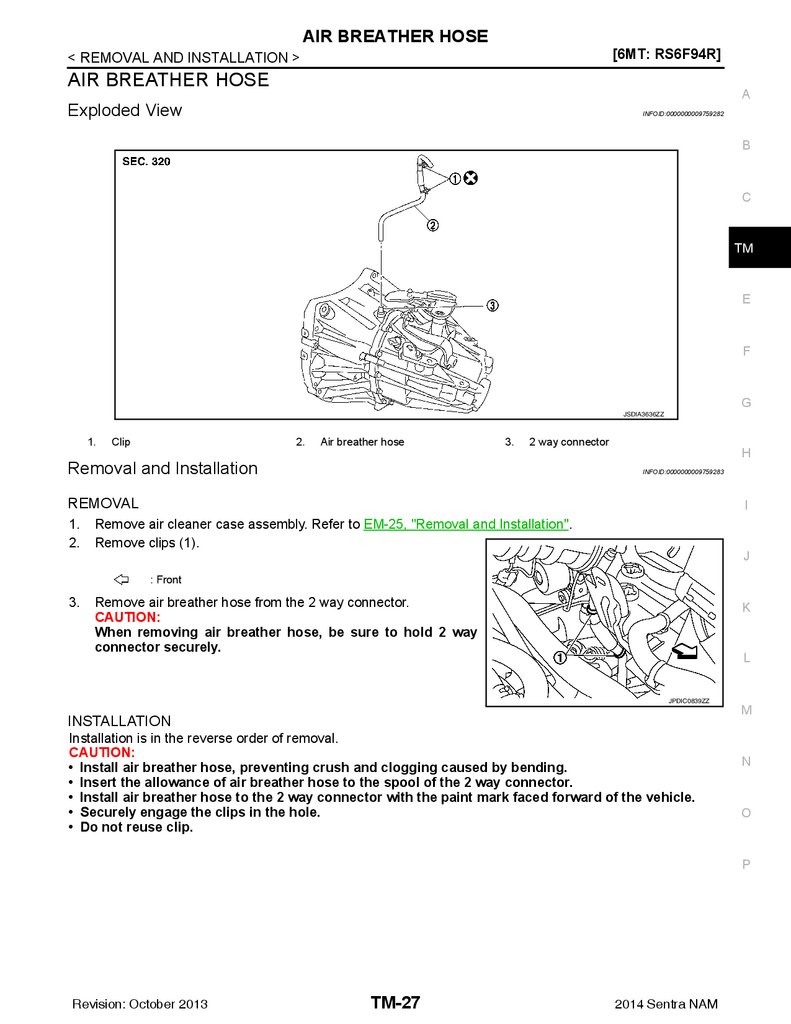
1.
Clip
2.
Air breather hose
3.
2 way connector
Removal and Installation
H
INFOID:0000000009759283
REMOVAL
1.
2.
I
Remove air cleaner case assembly. Refer to EM-25, "Removal and Installation".
Remove clips (1).
J
: Front
3.
Remove air breather hose from the 2 way connector.
CAUTION:
When removing air breather hose, be sure to hold 2 way
connector securely.
K
L
JPDIC0839ZZ
INSTALLATION
Installation is in the reverse order of removal.
CAUTION:
• Install air breather hose, preventing crush and clogging caused by bending.
• Insert the allowance of air breather hose to the spool of the 2 way connector.
• Install air breather hose to the 2 way connector with the paint mark faced forward of the vehicle.
• Securely engage the clips in the hole.
• Do not reuse clip.
M
N
O
P
Revision: October 2013
TM-27
2014 Sentra NAM
28.
TRANSAXLE ASSEMBLY[6MT: RS6F94R]
< UNIT REMOVAL AND INSTALLATION >
UNIT REMOVAL AND INSTALLATION
TRANSAXLE ASSEMBLY
Exploded View
INFOID:0000000009759284
JPDIC0137ZZ
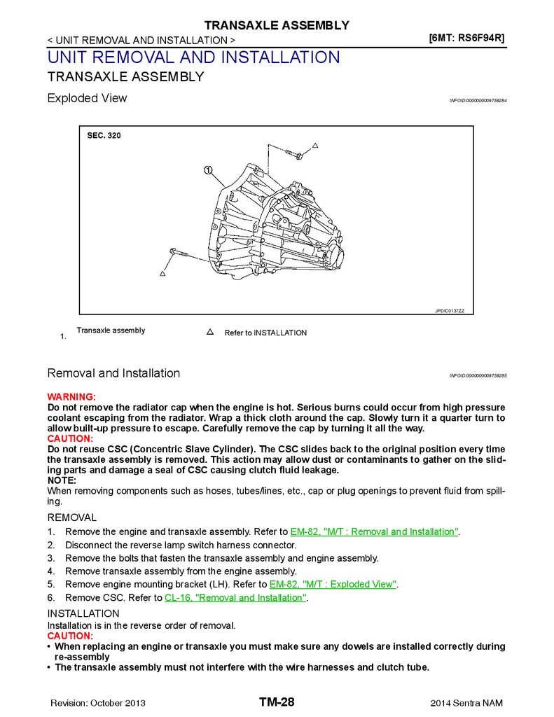
1.
Transaxle assembly
Refer to INSTALLATION
Removal and Installation
INFOID:0000000009759285
WARNING:
Do not remove the radiator cap when the engine is hot. Serious burns could occur from high pressure
coolant escaping from the radiator. Wrap a thick cloth around the cap. Slowly turn it a quarter turn to
allow built-up pressure to escape. Carefully remove the cap by turning it all the way.
CAUTION:
Do not reuse CSC (Concentric Slave Cylinder). The CSC slides back to the original position every time
the transaxle assembly is removed. This action may allow dust or contaminants to gather on the sliding parts and damage a seal of CSC causing clutch fluid leakage.
NOTE:
When removing components such as hoses, tubes/lines, etc., cap or plug openings to prevent fluid from spilling.
REMOVAL
1.
2.
3.
4.
5.
6.
Remove the engine and transaxle assembly. Refer to EM-82, "M/T : Removal and Installation".
Disconnect the reverse lamp switch harness connector.
Remove the bolts that fasten the transaxle assembly and engine assembly.
Remove transaxle assembly from the engine assembly.
Remove engine mounting bracket (LH). Refer to EM-82, "M/T : Exploded View".
Remove CSC. Refer to CL-16, "Removal and Installation".
INSTALLATION
Installation is in the reverse order of removal.
CAUTION:
• When replacing an engine or transaxle you must make sure any dowels are installed correctly during
re-assembly
• The transaxle assembly must not interfere with the wire harnesses and clutch tube.
Revision: October 2013
TM-28
2014 Sentra NAM
29.
TRANSAXLE ASSEMBLY[6MT: RS6F94R]
< UNIT REMOVAL AND INSTALLATION >
• Improper alignment caused by missing dowels may cause vibration, oil leaks or breakage of drive
train components.
• When installing transaxle assembly, do not bring input shaft into contact with clutch cover.
• Tapping work for tapping bolts is not applied to new transaxle case. Do not perform tapping by other
than screwing tapping bolts because tapping is formed by screwing tapping bolts into transaxle
case.
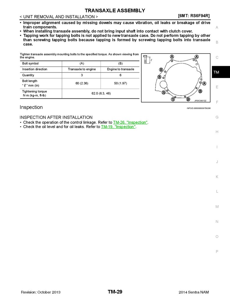
Tighten transaxle assembly mounting bolts to the specified torque. As shown viewing from
the engine.
Bolt symbol
Insertion direction
Quantity
Bolt length
“ ” mm (in)
Tightening torque
N·m (kg-m, ft-lb)
(A)
(B)
Transaxle to engine
Engine to transaxle
3
6
60 (2.36)
50 (1.97)
A
B
C
TM
E
62.0 (6.3, 46)
JPDIC0837ZZ
Inspection
F
INFOID:0000000009759286
INSPECTION AFTER INSTALLATION
G
• Check the operation of the control linkage. Refer to TM-26, "Inspection".
• Check the oil level and for oil leaks. Refer to TM-19, "Inspection".
H
I
J
K
L
M
N
O
P
Revision: October 2013
TM-29
2014 Sentra NAM
30.
TRANSAXLE ASSEMBLY[6MT: RS6F94R]
< UNIT DISASSEMBLY AND ASSEMBLY >
UNIT DISASSEMBLY AND ASSEMBLY
TRANSAXLE ASSEMBLY
Exploded View
INFOID:0000000009759287
CASE AND HOUSING
JPDIC0437GB
1.
Filler plug
2.
Gasket
3.
Transaxle case
4.
Bushing
5.
Snap ring
6.
Oil channel
7.
Oil gutter
8.
Position switch
9.
Bracket
10.
Differential side oil seal
11.
Magnet
12.
Drain plug
13.
Input shaft oil seal
14.
Clutch housing
15.
2 way connector
16.
Plug
17.
Pinion shaft
18.
Pinion gear
SHAFT AND GEAR
Revision: October 2013
TM-30
2014 Sentra NAM
31.
TRANSAXLE ASSEMBLY[6MT: RS6F94R]
< UNIT DISASSEMBLY AND ASSEMBLY >
A
B
C
TM
E
F
G
H
I
J
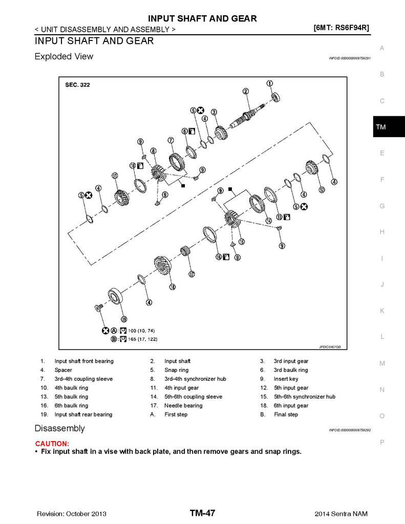
JPDIC0407GB
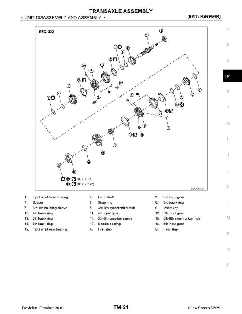
1.
Input shaft front bearing
2.
Input shaft
3.
4.
Spacer
5.
Snap ring
6.
3rd baulk ring
7.
3rd-4th coupling sleeve
8.
3rd-4th synchronizer hub
9.
Insert key
10.
4th baulk ring
11.
4th input gear
12.
5th input gear
13.
5th baulk ring
14.
5th-6th coupling sleeve
15.
5th-6th synchronizer hub
16.
6th baulk ring
17.
Needle bearing
18.
6th input gear
19.
Input shaft rear bearing
A.
First step
B.
Final step
K
3rd input gear
L
M
N
O
P
Revision: October 2013
TM-31
2014 Sentra NAM
32.
TRANSAXLE ASSEMBLY[6MT: RS6F94R]
< UNIT DISASSEMBLY AND ASSEMBLY >
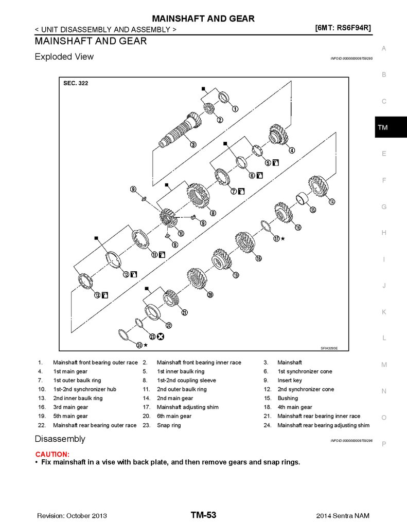
SFIA3293E
1.
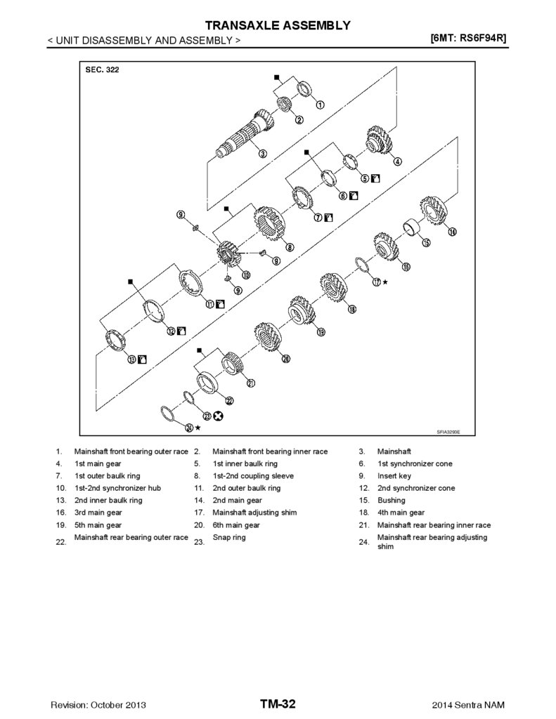
Mainshaft front bearing outer race 2.
Mainshaft front bearing inner race
3.
Mainshaft
4.
1st main gear
5.
1st inner baulk ring
6.
1st synchronizer cone
7.
1st outer baulk ring
8.
1st-2nd coupling sleeve
9.
Insert key
10.
1st-2nd synchronizer hub
11.
2nd outer baulk ring
12.
2nd synchronizer cone
13.
2nd inner baulk ring
14.
2nd main gear
15.
Bushing
16.
3rd main gear
17.
Mainshaft adjusting shim
18.
4th main gear
5th main gear
20.
6th main gear
21.
Mainshaft rear bearing inner race
24.
Mainshaft rear bearing adjusting
shim
19.
22.
Mainshaft rear bearing outer race
Revision: October 2013
23.
Snap ring
TM-32
2014 Sentra NAM
33.
TRANSAXLE ASSEMBLY[6MT: RS6F94R]
< UNIT DISASSEMBLY AND ASSEMBLY >
A
B
C
TM
E
F
G
H
I
JPDIC0425GB
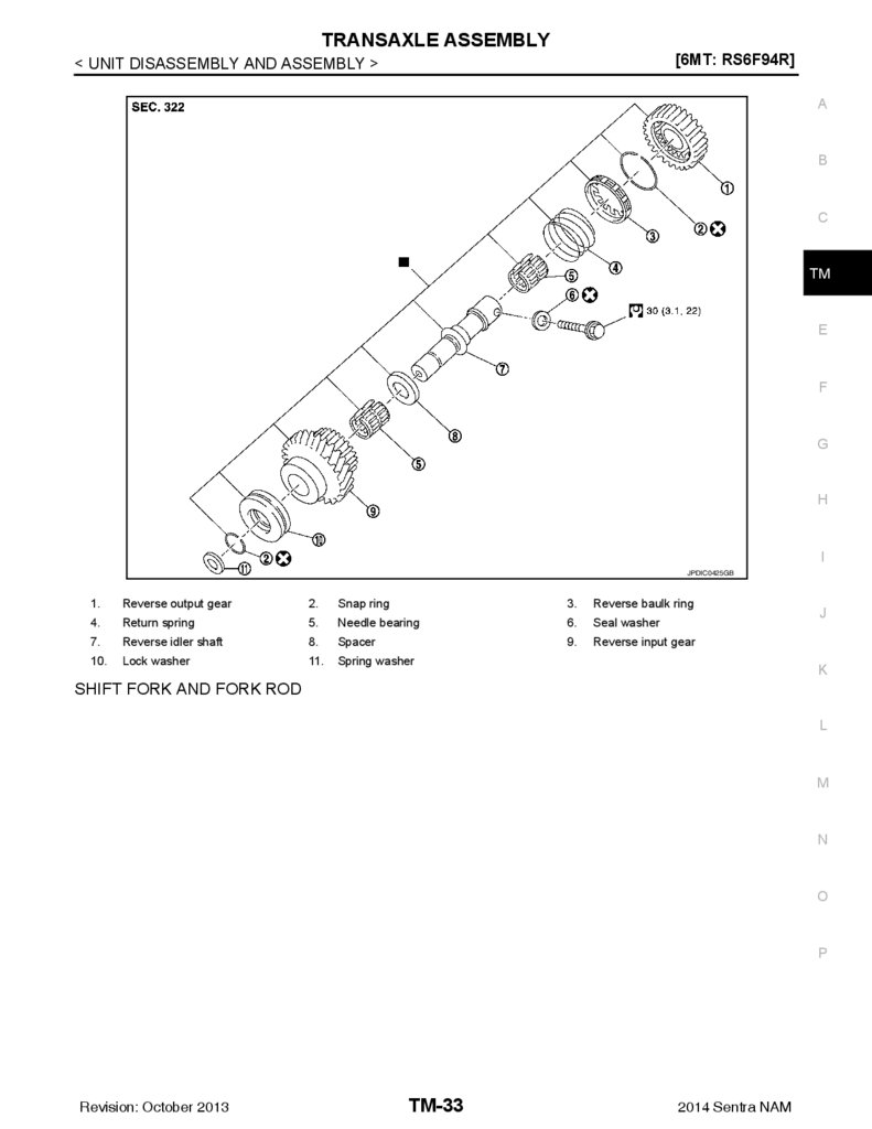
1.
Reverse output gear
2.
Snap ring
3.
Reverse baulk ring
4.
Return spring
5.
Needle bearing
6.
Seal washer
7.
Reverse idler shaft
8.
Spacer
9.
Reverse input gear
10.
Lock washer
11.
Spring washer
J
K
SHIFT FORK AND FORK ROD
L
M
N
O
P
Revision: October 2013
TM-33
2014 Sentra NAM
34.
TRANSAXLE ASSEMBLY[6MT: RS6F94R]
< UNIT DISASSEMBLY AND ASSEMBLY >
JPDIC0603ZZ
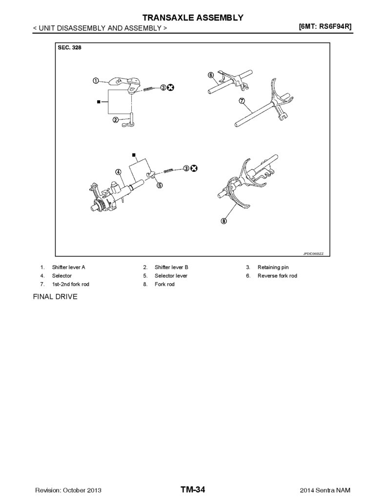
1.
Shifter lever A
2.
Shifter lever B
3.
Retaining pin
4.
Selector
5.
Selector lever
6.
Reverse fork rod
7.
1st-2nd fork rod
8.
Fork rod
FINAL DRIVE
Revision: October 2013
TM-34
2014 Sentra NAM
35.
TRANSAXLE ASSEMBLY[6MT: RS6F94R]
< UNIT DISASSEMBLY AND ASSEMBLY >
A
B
C
TM
E
F
G
H
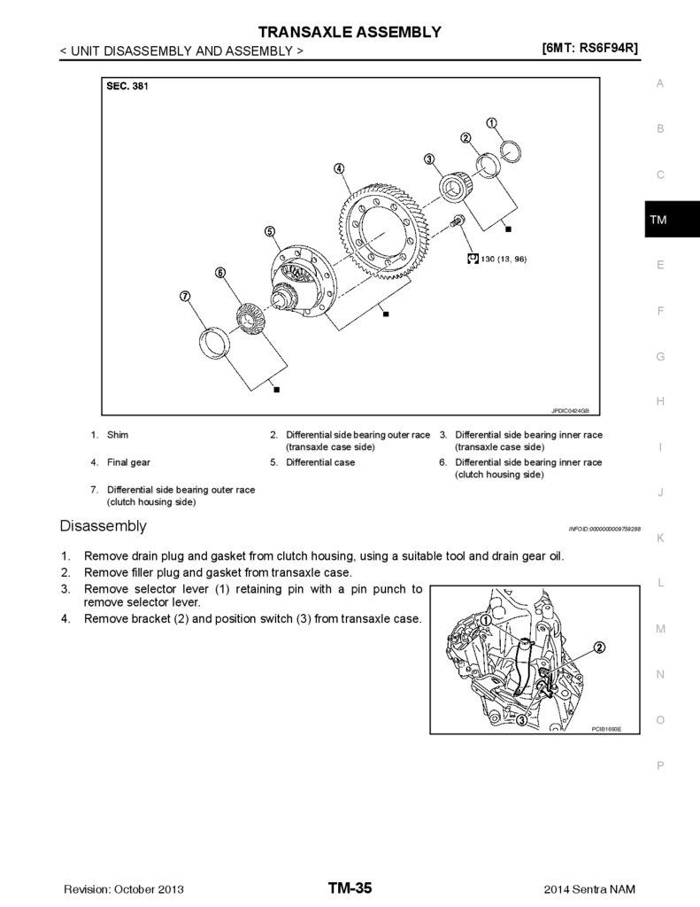
JPDIC0424GB
1. Shim
2. Differential side bearing outer race 3. Differential side bearing inner race
(transaxle case side)
(transaxle case side)
4. Final gear
5. Differential case
7. Differential side bearing outer race
(clutch housing side)
J
Disassembly
1.
2.
3.
4.
I
6. Differential side bearing inner race
(clutch housing side)
INFOID:0000000009759288
Remove drain plug and gasket from clutch housing, using a suitable tool and drain gear oil.
Remove filler plug and gasket from transaxle case.
Remove selector lever (1) retaining pin with a pin punch to
remove selector lever.
Remove bracket (2) and position switch (3) from transaxle case.
K
L
M
N
O
PCIB1693E
P
Revision: October 2013
TM-35
2014 Sentra NAM
36.
TRANSAXLE ASSEMBLY[6MT: RS6F94R]
< UNIT DISASSEMBLY AND ASSEMBLY >
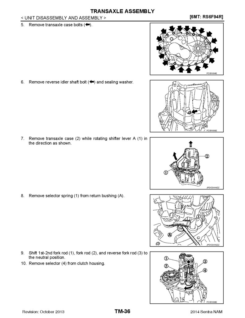
5.
Remove transaxle case bolts (
).
PCIB1694E
6.
Remove reverse idler shaft bolt (
) and sealing washer.
PCIB1695E
7.
Remove transaxle case (2) while rotating shifter lever A (1) in
the direction as shown.
JPDIC0444ZZ
8.
Remove selector spring (1) from return bushing (A).
JPDIC0445ZZ
9.
Shift 1st-2nd fork rod (1), fork rod (2), and reverse fork rod (3) to
the neutral position.
10. Remove selector (4) from clutch housing.
PCIB1698E
Revision: October 2013
TM-36
2014 Sentra NAM
37.
TRANSAXLE ASSEMBLY[6MT: RS6F94R]
< UNIT DISASSEMBLY AND ASSEMBLY >
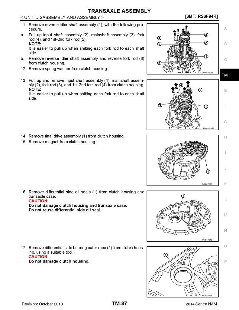
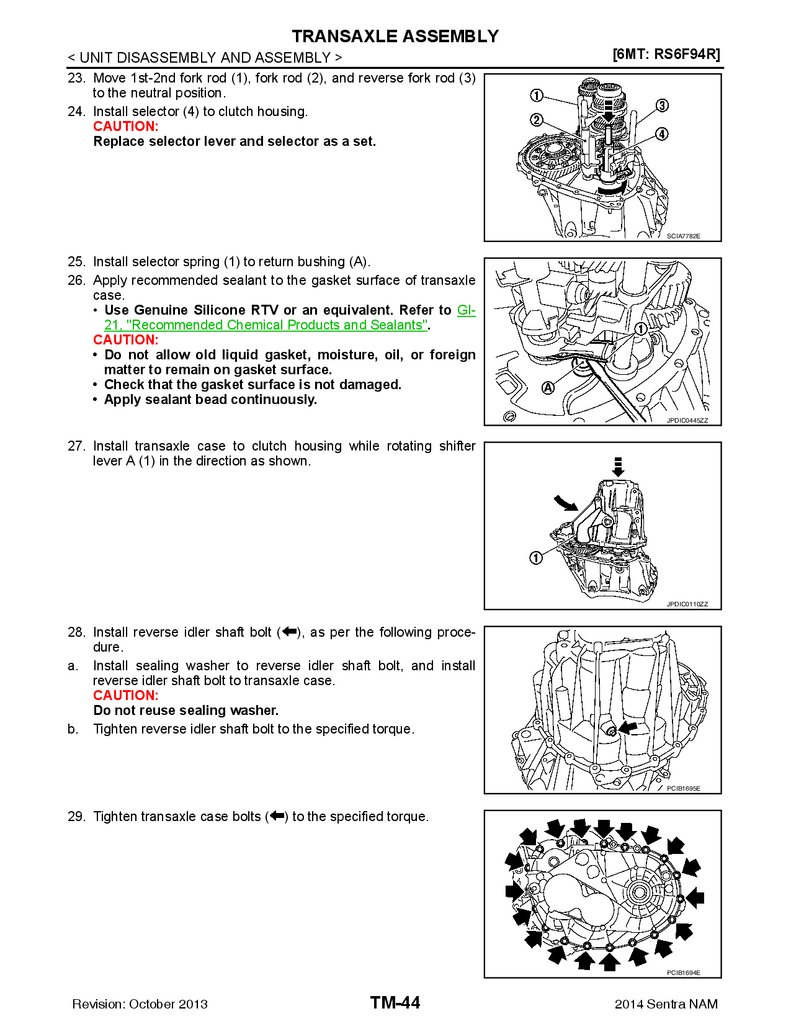
11. Remove reverse idler shaft assembly (1), with the following procedure.
a. Pull up input shaft assembly (2), mainshaft assembly (3), fork
rod (4), and 1st-2nd fork rod (5).
NOTE:
It is easier to pull up when shifting each fork rod to each shaft
side.
b. Remove reverse idler shaft assembly and reverse fork rod (6)
from clutch housing.
12. Remove spring washer from clutch housing.
A
B
C
JPDIC0606ZZ
13. Pull up and remove input shaft assembly (1), mainshaft assembly (2), fork rod (3), and 1st-2nd fork rod (4) from clutch housing.
NOTE:
It is easier to pull up when shifting each fork rod to each shaft
side.
TM
E
F
G
JPDIC0607ZZ
14. Remove final drive assembly (1) from clutch housing.
15. Remove magnet from clutch housing.
H
I
J
PCIB1703E
16. Remove differential side oil seals (1) from clutch housing and
transaxle case.
CAUTION:
Do not damage clutch housing and transaxle case.
Do not reuse differential side oil seal.
K
L
M
N
PCIB1704E
O
17. Remove differential side bearing outer race (1) from clutch housing, using a suitable tool.
CAUTION:
Do not damage clutch housing.
P
PCIB1716E
Revision: October 2013
TM-37
2014 Sentra NAM
38.
TRANSAXLE ASSEMBLY[6MT: RS6F94R]
< UNIT DISASSEMBLY AND ASSEMBLY >
18. Remove differential side bearing outer race (1) from transaxle
case, using a suitable tool.
CAUTION:
Do not damage transaxle case.
19. Remove shim (2) from transaxle case.
PCIB1705E
20. Remove shifter lever A (1) retaining pin, using a suitable tool.
CAUTION:
Do not reuse retaining pin.
21. Remove shifter lever A from transaxle case.
JPDIC0106ZZ
22. Remove shifter lever B (1) from transaxle case.
PCIB1712E
23. Remove oil gutter (1) from transaxle case.
PCIB1707E
24. Remove bushings (1) from transaxle case, using a suitable tool.
CAUTION:
Do not reuse bushings.
PCIB1710E
Revision: October 2013
TM-38
2014 Sentra NAM
39.
TRANSAXLE ASSEMBLY[6MT: RS6F94R]
< UNIT DISASSEMBLY AND ASSEMBLY >
25. Remove mainshaft rear bearing outer race from transaxle case,
using a suitable tool.
26. Remove mainshaft rear bearing adjusting shim from transaxle
case.
A
B
C
PCIB1706E
27. Remove snap ring (1) and oil channel (2) from transaxle case.
CAUTION:
Do not reuse snap ring or oil channel.
TM
E
F
G
PCIB1708E
28. Remove input shaft oil seal (1) from clutch housing, using a suitable tool.
CAUTION:
Do not damage clutch housing.
Do not reuse input shaft oil seal.
H
I
J
PCIB1714E
29. Remove mainshaft front bearing outer race (1) from clutch housing, using Tool (A) and a suitable tool (B).
K
L
Tool number (A) : KV381054S0 (J-34286)
30. Remove oil channel (2) from clutch housing.
CAUTION:
Do not reuse oil channel.
M
N
JPDIC0107ZZ
O
31. Remove bushings (1) from clutch housing, using a suitable tool.
CAUTION:
Do not reuse bushings.
P
PCIB1717E
Revision: October 2013
TM-39
2014 Sentra NAM
40.
TRANSAXLE ASSEMBLY[6MT: RS6F94R]
< UNIT DISASSEMBLY AND ASSEMBLY >
32. Remove 2 way connector (1) from clutch housing.
PCIB1720E
Assembly
1.
INFOID:0000000009759289
Install 2 way connector (1) to clutch housing.
PCIB1720E
2.
3.
Install bushings (1) so that they becomes even with clutch housing surface, using suitable tool (A).
Install oil channel to clutch housing.
CAUTION:
Do not reuse oil channel.
JPDIC0108ZZ
4.
Install mainshaft front bearing outer race to clutch housing using
Tool (A).
CAUTION:
Replace mainshaft front bearing outer race and mainshaft
front bearing inner race as a set.
Do not reuse mainshaft front bearing inner or outer race.
Tool number (A) : KV38100200 (
—
)
PCIB1724E
5.
Install input shaft oil seal (1) to clutch housing using the Tool (A).
Revision: October 2013
TM-40
2014 Sentra NAM
41.
TRANSAXLE ASSEMBLY[6MT: RS6F94R]
< UNIT DISASSEMBLY AND ASSEMBLY >
Tool number (A) : ST33220000 (
—
)
A
B
C
PCIB1721E
6.
7.
8.
Install snap ring (1) and oil channel (2) to transaxle case.
CAUTION:
• Select and install snap ring that has the same thickness
as previous one.
• Replace transaxle assembly when replacing transaxle
case.
Install mainshaft rear bearing adjusting shim to transaxle case.
CAUTION:
Select mainshaft rear bearing adjusting shim, with the following procedure when replacing mainshaft adjusting
shim, 6th main gear, 5th main gear, or 4th main gear.
PCIB1729E
• Replace mainshaft adjusting shim.
- If new mainshaft adjusting shim is thinner than previous one, offset the thickness difference by
selecting thicker mainshaft rear bearing adjusting shim.
- If new mainshaft adjusting shim is thicker than previous one, offset the thickness difference by
selecting thinner mainshaft rear bearing adjusting shim.
• Replace 6th main gear, 5th main gear, or 4th main gear.
- Measure the thickness of the main gear used before and the new main gear
- Increase the thickness of the mainshaft rear bearing adjusting shim, if the difference is smaller
than 0.025 mm (0.0010 in).
- Decrease the thickness of the mainshaft rear bearing adjusting shim, if the difference is greater
than 0.025 mm (0.0010 in).
Install mainshaft rear bearing outer race to transaxle case using
suitable tool (A).
CAUTION:
Replace mainshaft rear bearing outer race and mainshaft
rear bearing inner race as a set.
Tool number
: KV38100200 (
—
TM
E
F
G
H
I
J
K
L
)
M
PCIB1728E
9.
N
Install bushings (1) to transaxle case, using suitable tool (A).
O
P
JPDIC0109ZZ
Revision: October 2013
TM-41
2014 Sentra NAM
42.
TRANSAXLE ASSEMBLY[6MT: RS6F94R]
< UNIT DISASSEMBLY AND ASSEMBLY >
10. Install oil gutter (1) to transaxle case.
PCIB1730E
11. Install shifter lever B (1) to transaxle case.
CAUTION:
Replace shifter lever A and shifter lever B as a set.
12. Install shifter lever A to transaxle case.
CAUTION:
Replace shifter lever A and shifter lever B as a set.
PCIB1712E
13. Install retaining pin to shifter lever A (1) using a suitable tool.
CAUTION:
Do not reuse retaining pin.
14. Install shim to transaxle case.
BCIA0047E
15. Install differential side bearing outer race (transaxle case side)
to transaxle case, using Tool (A).
CAUTION:
Replace differential side bearing outer race (transaxle case
side) and differential side bearing inner race (transaxle case
side) as a set.
Do not reuse differential side bearing inner or outer race.
Tool number
: ST33400001 (J-26082)
PCIB1726E
16. Install differential side bearing outer race (clutch housing side) to
clutch housing, using Tool (A).
CAUTION:
Replace differential side bearing outer race (clutch housing
side) and differential side bearing inner race (clutch housing side) as a set.
Do not reuse differential side bearing inner or outer race.
Tool number
: KV38100200 (
—
)
PCIB1722E
Revision: October 2013
TM-42
2014 Sentra NAM
43.
TRANSAXLE ASSEMBLY< UNIT DISASSEMBLY AND ASSEMBLY >
17. Install differential side oil seals (1) to clutch housing and transaxle case, using Tools.
Tool number
Tool number
[6MT: RS6F94R]
A
: KV32500QAA
: B.vi 1666-B
(A)
: Transaxle case side
(B)
: Clutch housing side
Dimension (L1)
Dimension (L2)
B
C
: 1.2 – 1.8 mm (0.047 – 0.071 in)
: 2.7 – 3.3 mm (0.106 – 0.130 in)
JPDIC0454ZZ
TM
CAUTION:
• Do not incline differential side oil seal.
• Do not damage clutch housing and transaxle case.
18. Install magnet to clutch housing.
19. Install final drive assembly to clutch housing.
20. Set fork rod (1) to input shaft assembly (2), and then install them
to clutch housing.
E
F
G
H
I
JPDIC0608ZZ
21. Install mainshaft assembly (1), with the following procedure.
a. Pull up input shaft assembly (2) and fork rod (3).
b. Set 1st-2nd fork rod (4) to mainshaft assembly and install them
to clutch housing.
J
K
L
JPDIC0609ZZ
22. Install reverse idler shaft assembly (1) with the following procedure.
a. Install spring washer to clutch housing.
b. Pull up input shaft assembly (2), mainshaft assembly (3), fork
rod (4), and 1st-2nd fork rod (5).
NOTE:
It is easier to pull up when shifting each fork rod to each shaft
side.
c. Set reverse fork rod (6) to reverse idler shaft assembly and
install them to clutch housing.
N
O
P
JPDIC0606ZZ
Revision: October 2013
TM-43
M
2014 Sentra NAM
44.
TRANSAXLE ASSEMBLY< UNIT DISASSEMBLY AND ASSEMBLY >
23. Move 1st-2nd fork rod (1), fork rod (2), and reverse fork rod (3)
to the neutral position.
24. Install selector (4) to clutch housing.
CAUTION:
Replace selector lever and selector as a set.
[6MT: RS6F94R]
SCIA7782E
25. Install selector spring (1) to return bushing (A).
26. Apply recommended sealant to the gasket surface of transaxle
case.
• Use Genuine Silicone RTV or an equivalent. Refer to GI21, "Recommended Chemical Products and Sealants".
CAUTION:
• Do not allow old liquid gasket, moisture, oil, or foreign
matter to remain on gasket surface.
• Check that the gasket surface is not damaged.
• Apply sealant bead continuously.
JPDIC0445ZZ
27. Install transaxle case to clutch housing while rotating shifter
lever A (1) in the direction as shown.
JPDIC0110ZZ
28. Install reverse idler shaft bolt ( ), as per the following procedure.
a. Install sealing washer to reverse idler shaft bolt, and install
reverse idler shaft bolt to transaxle case.
CAUTION:
Do not reuse sealing washer.
b. Tighten reverse idler shaft bolt to the specified torque.
PCIB1695E
29. Tighten transaxle case bolts (
) to the specified torque.
PCIB1694E
Revision: October 2013
TM-44
2014 Sentra NAM
45.
TRANSAXLE ASSEMBLY[6MT: RS6F94R]
< UNIT DISASSEMBLY AND ASSEMBLY >
30. Install position switch (1), with the following procedure.
a. Apply recommended sealant to threads of position switch.
• Use Genuine Silicone RTV or an equivalent.Refer to GI-21,
"Recommended Chemical Products and Sealants".
CAUTION:
Do not allow old liquid gasket, moisture, oil, or foreign matter to remain on thread.
b. Install position switch to transaxle case and tighten it to the
specified torque.
31. Install bracket (2) to transaxle case and tighten bolt to the specified torque.
32. Install selector lever (3) with the following procedure.
a. Install selector lever to transaxle case.
CAUTION:
Replace selector lever and selector as a set.
b. Install retaining pin to selector lever using a suitable tool.
CAUTION:
Do not reuse retaining pin.
33. Install drain plug with the following procedure.
a. Install gasket to drain plug.
CAUTION:
Do not reuse gasket.
b. Install drain plug to clutch housing using a suitable tool.
c. Tighten drain plug to the specified torque.
CAUTION:
Do not overtighten drain plug as this could cause the transaxle case to crack.
34. Install filler plug with the following procedure.
a. Install gasket to filler plug and install it to the transaxle case.
CAUTION:
Do not reuse gasket.
b. Tighten filler plug to the specified torque.
CAUTION:
Fill with gear oil before tighten filler plug to the specified torque.
Do not overtighten the filler plug as this could cause the transaxle case to crack.
Inspection
A
B
C
SCIA7784E
TM
E
F
G
H
I
J
K
INFOID:0000000009759290
L
INSPECTION AFTER DISASSEMBLY
M
N
O
P
Revision: October 2013
TM-45
2014 Sentra NAM
46.
TRANSAXLE ASSEMBLY[6MT: RS6F94R]
< UNIT DISASSEMBLY AND ASSEMBLY >
Check contact surface ( ) and sliding surface ( ) for excessive
wear, uneven wear, bend, and damage. Replace if necessary.
SCIA7785E
Revision: October 2013
TM-46
2014 Sentra NAM
47.
INPUT SHAFT AND GEAR[6MT: RS6F94R]
< UNIT DISASSEMBLY AND ASSEMBLY >
INPUT SHAFT AND GEAR
A
Exploded View
INFOID:0000000009759291
B
C
TM
E
F
G
H
I
J
K
L
JPDIC0407GB
1.
Input shaft front bearing
2.
Input shaft
3.
3rd input gear
4.
Spacer
5.
Snap ring
6.
3rd baulk ring
7.
3rd-4th coupling sleeve
8.
3rd-4th synchronizer hub
9.
Insert key
M
10.
4th baulk ring
11.
4th input gear
12.
5th input gear
13.
5th baulk ring
14.
5th-6th coupling sleeve
15.
5th-6th synchronizer hub
16.
6th baulk ring
17.
Needle bearing
18.
6th input gear
19.
Input shaft rear bearing
A.
First step
B.
Final step
Disassembly
N
O
INFOID:0000000009759292
P
CAUTION:
• Fix input shaft in a vise with back plate, and then remove gears and snap rings.
Revision: October 2013
TM-47
2014 Sentra NAM
48.
INPUT SHAFT AND GEAR< UNIT DISASSEMBLY AND ASSEMBLY >
• For removal of snap ring, set snap ring pliers and flat pliers at
both sides of snap ring. While expanding snap ring with snap
ring pliers, move snap ring with flat pliers.
• Disassemble gear components putting direction marks on the
parts that do not affect any functions.
[6MT: RS6F94R]
SCIA1755J
1.
Remove input shaft rear bearing bolt (1), using Tool (A).
CAUTION:
Do not reuse rear bearing bolt.
Tool number (A)
: KV32300QAM (
—
)
JPDIC0449ZZ
2.
a.
b.
Remove input shaft rear bearing (1) with the following procedure.
Set a suitable tool to input shaft rear bearing.
Remove input shaft rear bearing using suitable tool (A).
JPDIC0111ZZ
3.
4.
5.
6.
Remove spacer (1), 6th input gear (2), needle bearing, 6th baulk
ring, and 5th-6th synchronizer hub assembly (3).
Remove insert keys and 5th-6th coupling sleeve from 5th-6th
synchronizer hub.
Remove snap ring (1).
CAUTION:
Do not reuse snap ring.
Remove spacer, 5th baulk ring, 5th input gear (2), and spacer.
PCIB1750E
PCIB1754E
Revision: October 2013
TM-48
2014 Sentra NAM
49.
INPUT SHAFT AND GEAR< UNIT DISASSEMBLY AND ASSEMBLY >
7. Remove snap ring (1).
CAUTION:
Do not reuse snap ring.
8. Remove spacer, 4th input gear (2), 4th baulk ring, and 3rd-4th
synchronizer hub assembly (3).
9. Remove insert keys and 3rd-4th coupling sleeve from 3rd-4th
synchronizer hub.
[6MT: RS6F94R]
A
B
C
PCIB1753E
TM
10. Remove snap ring (1).
CAUTION:
Do not reuse snap ring.
11. Remove spacer, 3rd baulk ring, and 3rd input gear (2).
E
F
G
PCIB1752E
12. Set a suitable tool to input shaft front bearing (1), and then
remove input shaft front bearing.
H
I
J
K
PCIB1751E
Assembly
INFOID:0000000009759293
Assembly is in the reverse order of disassembly.
CAUTION:
• Replace transaxle assembly when replacing input shaft.
• For installation of snap ring, set snap ring pliers and flat pliers
at both sides of snap ring. While expanding snap ring with
snap ring pliers, move snap ring with flat pliers.
• Do not reuse snap ring.
• Check that snap ring is securely installed in a groove.
• Replace 3rd-4th coupling sleeve and 3rd-4th synchronizer
hub as a set.
• Replace 5th-6th coupling sleeve and 5th-6th synchronizer hub
as a set.
L
M
N
O
P
SCIA1755J
Revision: October 2013
TM-49
2014 Sentra NAM
50.
INPUT SHAFT AND GEAR< UNIT DISASSEMBLY AND ASSEMBLY >
• Be careful to install 3rd-4th synchronizer hub according to the
specified direction.
(A)
: 3rd input gear side
(B)
: 4th input gear side
[6MT: RS6F94R]
PCIB1748E
• Be careful to install 5th-6th synchronizer hub according to the specified direction.
(A)
: 5th input gear side
(B)
: 6th input gear side
PCIB1749E
• Install input shaft front bearing (1) using a suitable tool (A).
JPDIC0112ZZ
• Install input shaft rear bearing (1) using a suitable tool (A) and Tool
(B).
Tool number
: ST36720030 (
—
)
• Apply gear oil to 3rd baulk ring, 4th baulk ring, 5th baulk ring, and
6th baulk ring.
JPDIC0113ZZ
Revision: October 2013
TM-50
2014 Sentra NAM
51.
INPUT SHAFT AND GEAR< UNIT DISASSEMBLY AND ASSEMBLY >
• Install input shaft rear bearing bolt (1), as per the following procedure.
CAUTION:
Follow the procedures. Otherwise it may cause a transaxle
malfunction.
Do not reuse rear bearing bolt.
1. Fix the Tool (A) in a vise and set input shaft assembly.
Tool number : KV32300QAM (
2.
3.
4.
—
[6MT: RS6F94R]
A
B
C
)
Install input shaft rear bearing bolt and tighten it to the specified
torque of the first step.
Loosen input shaft rear bearing bolt by a half turn.
Tighten input shaft rear bearing bolt to the specified torque of the final step.
Inspection
JPDIC0449ZZ
TM
INFOID:0000000009759294
E
INSPECTION AFTER DISASSEMBLY
Input Shaft and Gear
Check the following items and replace if necessary.
• Damage, peeling, bend, uneven wear, and distortion of shaft.
• Excessive wear, damage, and peeling of gear.
F
G
H
I
SCIA7736E
Synchronizer Hub and Coupling Sleeve
Check the following items and replace if necessary.
• Breakage, damage, and unusual wear on contact surface of coupling sleeve, synchronizer hub, and insert key.
• Coupling sleeve and synchronizer hub move smoothly.
J
K
L
SCIA1753J
Baulk Ring
Check contact surface of baulk ring cam and insert key for excessive
wear, uneven wear, bend, and damage. Replace if necessary.
M
N
O
P
SCIA0608J
Bearing
Revision: October 2013
TM-51
2014 Sentra NAM
52.
INPUT SHAFT AND GEAR< UNIT DISASSEMBLY AND ASSEMBLY >
Check bearing for damage and uneven rotation. Replace if necessary.
[6MT: RS6F94R]
MTF0041D
Revision: October 2013
TM-52
2014 Sentra NAM
53.
MAINSHAFT AND GEAR[6MT: RS6F94R]
< UNIT DISASSEMBLY AND ASSEMBLY >
MAINSHAFT AND GEAR
A
Exploded View
INFOID:0000000009759295
B
C
TM
E
F
G
H
I
J
K
L
SFIA3293E
1.
Mainshaft front bearing outer race 2.
Mainshaft front bearing inner race
3.
Mainshaft
4.
1st main gear
5.
1st inner baulk ring
6.
1st synchronizer cone
7.
1st outer baulk ring
8.
1st-2nd coupling sleeve
9.
Insert key
10.
1st-2nd synchronizer hub
11.
2nd outer baulk ring
12.
2nd synchronizer cone
13.
2nd inner baulk ring
14.
2nd main gear
15.
Bushing
16.
3rd main gear
17.
Mainshaft adjusting shim
18.
4th main gear
19.
5th main gear
20.
6th main gear
21.
Mainshaft rear bearing inner race
22.
Mainshaft rear bearing outer race
23.
Snap ring
24.
Mainshaft rear bearing adjusting shim
Disassembly
INFOID:0000000009759296
CAUTION:
• Fix mainshaft in a vise with back plate, and then remove gears and snap rings.
Revision: October 2013
TM-53
2014 Sentra NAM
M
N
O
P
54.
MAINSHAFT AND GEAR< UNIT DISASSEMBLY AND ASSEMBLY >
• For removal of snap ring, set snap ring pliers and flat pliers at
both sides of snap ring. While expanding snap ring with snap
ring pliers, move snap ring with flat pliers.
• Disassemble gear components putting direction marks on the
parts that never affect any functions.
[6MT: RS6F94R]
SCIA1755J
1.
Remove snap ring (1).
CAUTION:
Do not reuse snap ring.
PCIB1745E
2.
a.
b.
Remove 6th main gear (1) and mainshaft rear bearing inner race
(2), with the following procedure.
Set a suitable tool to 6th main gear.
Remove mainshaft rear bearing inner race and 6th main gear,
using Tool (A).
Tool number : ST33052000 (
—
)
PCIB1744E
3.
a.
b.
Remove 4th main gear (1) and 5th main gear (2) with the following procedure.
Set a suitable tool to 4th main gear.
Remove 5th main gear and 4th main gear, using Tool (A).
Tool number
4.
: ST33052000 (
—
)
Remove mainshaft adjusting shim.
PCIB1743E
Revision: October 2013
TM-54
2014 Sentra NAM
55.
MAINSHAFT AND GEAR< UNIT DISASSEMBLY AND ASSEMBLY >
5. Remove 1st main gear (1), 1st-2nd synchronizer hub assembly
(2), 2nd main gear (3), and 3rd main gear (4) with the following
procedure.
a. Set a suitable tool to 1st main gear.
b. Remove 3rd main gear, busing, 2nd main gear, 2nd inner baulk
ring, 2nd synchronizer cone, 2nd outer baulk ring, 1st-2nd synchronizer hub assembly, 1st outer baulk ring, 1st synchronizer
cone, 1st inner baulk ring, and 1st main gear using Tool (A).
Tool number
: ST33052000 (
—
[6MT: RS6F94R]
A
B
C
)
PCIB1742E
c.
6.
a.
b.
Remove insert keys and 1st-2nd coupling sleeve from 1st-2nd
synchronizer hub.
Remove mainshaft front bearing inner race (1) with the following
procedure.
Set a suitable tool to mainshaft front bearing inner race.
Remove mainshaft front bearing inner race using Tool (A).
TM
E
F
Tool number : ST33052000 (
—
)
G
PCIB1741E
H
Assembly
INFOID:0000000009759297
CAUTION:
• Select mainshaft rear bearing adjusting shim, as per the following procedure when replacing mainshaft adjusting shim, 6th main gear, 5th main gear, or 4th main gear.
- Replace mainshaft adjusting shim.
• If new mainshaft adjusting shim is thinner than previous one, offset the thickness difference by
selecting thicker mainshaft rear bearing adjusting shim.
• If new mainshaft adjusting shim is thicker than previous one, offset the thickness difference by
selecting thinner mainshaft rear bearing adjusting shim.
- Replace 6th main gear, 5th main gear, or 4th main gear.
• Measure the thickness of the main gear used before and the new main gear
• Increase the thickness of the mainshaft rear bearing adjusting shim, if the difference is smaller than
0.025 mm (0.0010 in).
• Replace transaxle assembly when replacing mainshaft.
• For installation of snap ring, set snap ring pliers and flat pliers
at both sides of snap ring. While expanding snap ring with
snap ring pliers, move snap ring with flat pliers.
• Do not reuse snap ring.
I
J
K
L
M
N
O
SCIA1755J
P
Revision: October 2013
TM-55
2014 Sentra NAM
56.
MAINSHAFT AND GEAR< UNIT DISASSEMBLY AND ASSEMBLY >
1. Install mainshaft front bearing inner race (1) using Tool (A).
CAUTION:
Replace mainshaft front bearing outer race and mainshaft
front bearing inner race as a set.
Do not reuse mainshaft front bearing inner or outer race.
Tool number : ST36720030 (
2.
3.
4.
5.
—
[6MT: RS6F94R]
)
Apply gear oil to 1st inner baulk ring, 1st synchronizer cone, 1st
outer baulk ring, 2nd inner baulk ring, 2nd synchronizer cone,
and 2nd outer baulk ring.
PCIB1733E
CAUTION:
• Replace 1st inner baulk ring, 1st synchronizer cone, and 1st outer baulk ring as a set.
• Replace 2nd inner baulk ring, 2nd synchronizer cone, and 2nd outer baulk ring as a set.
Install insert keys and 1st-2nd coupling sleeve to 1st-2nd synchronizer hub.
CAUTION:
Replace 1st-2nd synchronizer hub and 1st-2nd coupling sleeve as a set.
Install 1st main gear (1), 1st inner baulk ring, 1st synchronizer
cone, 1st outer baulk ring, 1st-2nd synchronizer hub assembly
(2), 2nd inner baulk ring, 2nd synchronizer cone, and 2nd outer
baulk ring.
Install bushing (3) using Tool (A).
Tool number : ST32102700 (
—
)
PCIB1734E
6.
Install 3rd main gear (1) and 2nd main gear (2) using Tool (A).
Tool number
: KV32102700 (
—
)
PCIB1735E
7.
Measure dimension (L) as shown in the figure. Select mainshaft
adjusting shim (1) according to the following list, and then install
it to mainshaft.
(2)
: Mainshaft
(3)
: 3rd main gear
Unit: mm (in)
Dimension (L)
Mainshaft adjusting shim thickness
147.690 – 147.666 (5.8146 – 5.8136)
1.500 (0.0591)
147.665 – 147.641 (5.8136 – 5.8126)
1.525 (0.0600)
147.640 – 147.616 (5.8126 – 5.8116)
1.550 (0.0610)
147.615 – 147.591 (5.8116 – 5.8107)
1.575 (0.0620)
147.590 – 147.566 (5.8106 – 5.8097)
1.600 (0.0630)
147.565 – 147.541 (5.8096 – 5.8087)
1.625 (0.0640)
147.540 – 147.516 (5.8086 – 5.8077)
1.650 (0.0650)
Revision: October 2013
TM-56
PCIB1736E
2014 Sentra NAM
57.
MAINSHAFT AND GEAR[6MT: RS6F94R]
< UNIT DISASSEMBLY AND ASSEMBLY >
Dimension (L)
Mainshaft adjusting shim thickness
147.515 – 147.491 (5.8077 – 5.8067)
1.675 (0.0659)
147.490 – 147.466 (5.8067 – 5.8057)
1.700 (0.0669)
147.465 – 147.441 (5.8057 – 5.8048)
1.725 (0.0679)
147.440 – 147.416 (5.8047 – 5.8038)
1.750 (0.0689)
147.415 – 147.391 (5.8037 – 5.8028)
1.775 (0.0699)
8.
A
B
C
Install 4th main gear (1) using Tool (A).
Tool number : KV32102700 (
—
)
TM
E
F
PCIB1737E
9.
Install 5th main gear (1) using Tool (A).
Tool number : KV32102700 (
G
—
)
H
I
J
PCIB1738E
10. Install 6th main gear (1) using Tool (A).
Tool number : KV32102700 (
K
—
)
L
M
PCIB1739E
11. Install mainshaft rear bearing inner race (1) using Tool (A).
CAUTION:
Replace mainshaft rear bearing inner race and mainshaft
rear bearing outer race as a set.
Tool number
O
: ST30901000 (J-26010-01)
P
12. Install snap ring.
CAUTION:
Do not reuse snap ring.
PCIB1740E
Revision: October 2013
TM-57
N
2014 Sentra NAM
58.
MAINSHAFT AND GEAR[6MT: RS6F94R]
< UNIT DISASSEMBLY AND ASSEMBLY >
Inspection
INFOID:0000000009759298
INSPECTION AFTER DISASSEMBLY
Mainshaft and Gear
Check the following items and replace if necessary.
• Damage, peeling, bend, uneven wear, and distortion of shaft.
• Excessive wear, damage, and peeling of gear.
PCIB1775E
Synchronizer Hub and Coupling Sleeve
Check the following items and replace if necessary.
• Breakage, damage, and unusual wear on contact surface of coupling sleeve, synchronizer hub, and insert key.
• Coupling sleeve and synchronizer hub move smoothly.
SCIA1753J
Baulk Ring
Check contact surface of baulk ring cam and insert key for excessive
wear, uneven wear, bend, and damage. Replace if necessary.
SCIA0608J
Bearing
Check bearing for damage and uneven rotation. Replace if necessary.
CAUTION:
• Replace mainshaft front bearing outer race and mainshaft
front bearing inner race as a set.
• Replace mainshaft rear bearing inner race and mainshaft rear
bearing outer race as a set.
SPD715
Revision: October 2013
TM-58
2014 Sentra NAM
59.
REVERSE IDLER SHAFT AND GEAR[6MT: RS6F94R]
< UNIT DISASSEMBLY AND ASSEMBLY >
REVERSE IDLER SHAFT AND GEAR
A
Exploded View
INFOID:0000000009759299
B
C
TM
E
F
G
H
I
J
JPDIC0425GB
1.
Reverse output gear
2.
Snap ring
3.
Reverse baulk ring
4.
Return spring
5.
Needle bearing
6.
Seal washer
7.
Reverse idler shaft
8.
Spacer
9.
Reverse input gear
10.
Lock washer
11.
Spring washer
Disassembly
1.
K
L
INFOID:0000000009759300
M
Remove reverse output gear (1).
N
O
P
PCIB1760E
Revision: October 2013
TM-59
2014 Sentra NAM
60.
REVERSE IDLER SHAFT AND GEAR[6MT: RS6F94R]
< UNIT DISASSEMBLY AND ASSEMBLY >
2. Remove snap ring (1).
CAUTION:
Do not reuse snap ring.
PCIB1759E
3.
Remove reverse baulk ring (1) and return spring (2).
PCIB1758E
4.
Remove snap ring (1), lock washer (2), and reverse input gear
(3).
CAUTION:
Do not reuse snap ring.
PCIB1757E
5.
Remove needle bearings (1) and washer.
PCIB1761E
Assembly
INFOID:0000000009759301
Assembly is in the reverse order of disassembly.
CAUTION:
• Do not reuse snap ring.
• Check that snap ring is securely installed in a groove.
• Replace reverse output gear, snap ring, reverse baulk ring, return spring, needle bearing, reverse
idler shaft, spacer, reverse input gear, and lock washer as a set.
Inspection
INFOID:0000000009759302
INSPECTION AFTER DISASSEMBLY
Revision: October 2013
TM-60
2014 Sentra NAM
61.
REVERSE IDLER SHAFT AND GEAR[6MT: RS6F94R]
< UNIT DISASSEMBLY AND ASSEMBLY >
Shaft and Gear
Check the following items. Replace reverse output gear, snap ring, reverse baulk ring, return spring, needle
bearing, reverse idler shaft, spacer, reverse input gear, and lock washer as a set, if necessary.
• Damage, peeling, bend, uneven wear, and distortion of shaft
• Excessive wear, damage, and peeling of gear
Bearing
Check damage and rotation of bearing. Replace reverse output gear, snap ring, reverse baulk ring, return
spring, needle bearing, reverse idler shaft, spacer, reverse input gear, and lock washer as a set, if necessary.
A
B
C
TM
E
F
G
H
I
J
K
L
M
N
O
P
Revision: October 2013
TM-61
2014 Sentra NAM
62.
FINAL DRIVE[6MT: RS6F94R]
< UNIT DISASSEMBLY AND ASSEMBLY >
FINAL DRIVE
Exploded View
INFOID:0000000009759303
JPDIC0424GB
1.
Shim
2.
Differential side bearing outer race
(transaxle case side)
3.
Differential side bearing inner race
(transaxle case side)
4.
Final gear
5.
Differential case
6.
Differential side bearing inner race
(clutch housing side)
7.
Differential side bearing outer race
(clutch housing side)
Disassembly
1.
a.
b.
INFOID:0000000009759304
Remove differential side bearing inner race (clutch housing side)
(1) with the following procedure.
Set a suitable tool to differential side bearing inner race (clutch
housing side).
Remove differential side bearing inner race (clutch housing side)
using Tool (A).
Tool number : ST33061000 (J-8107-2)
PCIB1767E
Revision: October 2013
TM-62
2014 Sentra NAM
63.
FINAL DRIVE< UNIT DISASSEMBLY AND ASSEMBLY >
2. Remove final gear mounting bolts and remove final gear (1).
[6MT: RS6F94R]
A
B
C
JPDIC0446ZZ
3.
a.
b.
TM
Remove differential side bearing inner race (transaxle case
side) (1) with the following procedure.
Set a suitable tool to differential side bearing inner race (transaxle case side).
Remove differential side bearing inner race (transaxle case
side) using a suitable tool (A).
E
F
G
JPDIC0114ZZ
Assembly
1.
2.
INFOID:0000000009759305
Install final gear, and then tighten final gear mounting bolts to the specified torque.
CAUTION:
Replace final gear and differential case as a set.
Install differential side bearing inner race (clutch housing side)
using a suitable tool (A).
CAUTION:
Replace differential side bearing inner race (clutch housing
side) and differential side bearing outer race (clutch housing side) as a set.
H
I
J
K
L
JPDIC0115ZZ
3.
Install differential side bearing inner race (transaxle case side)
using a suitable tool (A).
CAUTION:
Replace differential side bearing inner race (transaxle case
side) and differential side bearing outer race (transaxle
case side) as a set.
M
N
O
JPDIC0116ZZ
Inspection
INFOID:0000000009759306
INSPECTION AFTER DISASSEMBLY
Gear and Case
Check final gear and differential case. Replace if necessary.
Revision: October 2013
TM-63
2014 Sentra NAM
P
64.
FINAL DRIVE[6MT: RS6F94R]
< UNIT DISASSEMBLY AND ASSEMBLY >
Bearing
Check bearing for damage and uneven rotation. Replace if necessary.
SPD715
Revision: October 2013
TM-64
2014 Sentra NAM
65.
SERVICE DATA AND SPECIFICATIONS (SDS)[6MT: RS6F94R]
< SERVICE DATA AND SPECIFICATIONS (SDS)
SERVICE DATA AND SPECIFICATIONS (SDS)
A
SERVICE DATA AND SPECIFICATIONS (SDS)
General Specifications
INFOID:0000000009759307
Transaxle type
RS6F94R
Engine type
MRA8DE
Model code number
B
C
ET80A
Number of speed
TM
6
Synchromesh type
Warner
Shift pattern
E
F
PCIB1769E
Gear ratio
1st
3.7273
2nd
2.1053
3rd
1.5185
4th
1.1714
5th
0.9143
6th
0.7674
Reverse
3.6865
Final gear
Number of teeth
Input gear
Main gear
11
2nd
19
3rd
27
4th
35
5th
35
6th
43
Reverse
11
1st
41
2nd
40
3rd
41
4th
41
5th
32
6th
33
Reverse
42
Reverse idler gear
Input/Output
28/29
Final gear
Final gear/Pinion
59/15
Side gear/Pinion mate gear
13/10
(US pt, Imp pt)
Reverse synchronizer
I
J
K
L
M
N
O
P
Approx. 2.0 (4-1/4, 3-1/2)
Installed
Triple-cone synchronizer
Revision: October 2013
H
3.9333
1st
Oil capacity (Reference)
Remarks
G
1st and 2nd
TM-65
2014 Sentra NAM
66.
PRECAUTIONS[CVT: RE0F11A]
< PRECAUTION >
PRECAUTION
PRECAUTIONS
Precaution for Supplemental Restraint System (SRS) "AIR BAG" and "SEAT BELT
PRE-TENSIONER"
INFOID:0000000010290139
The Supplemental Restraint System such as “AIR BAG” and “SEAT BELT PRE-TENSIONER”, used along
with a front seat belt, helps to reduce the risk or severity of injury to the driver and front passenger for certain
types of collision. Information necessary to service the system safely is included in the SR and SB section of
this Service Manual.
WARNING:
• To avoid rendering the SRS inoperative, which could increase the risk of personal injury or death in
the event of a collision which would result in air bag inflation, all maintenance must be performed by
an authorized NISSAN/INFINITI dealer.
• Improper maintenance, including incorrect removal and installation of the SRS, can lead to personal
injury caused by unintentional activation of the system. For removal of Spiral Cable and Air Bag
Module, see the SR section.
• Do not use electrical test equipment on any circuit related to the SRS unless instructed to in this
Service Manual. SRS wiring harnesses can be identified by yellow and/or orange harnesses or harness connectors.
PRECAUTIONS WHEN USING POWER TOOLS (AIR OR ELECTRIC) AND HAMMERS
WARNING:
• When working near the Airbag Diagnosis Sensor Unit or other Airbag System sensors with the Ignition ON or engine running, DO NOT use air or electric power tools or strike near the sensor(s) with a
hammer. Heavy vibration could activate the sensor(s) and deploy the air bag(s), possibly causing
serious injury.
• When using air or electric power tools or hammers, always switch the Ignition OFF, disconnect the
battery and wait at least three minutes before performing any service.
Precaution for Procedure without Cowl Top Cover
INFOID:0000000009759309
When performing the procedure after removing cowl top cover, cover
the lower end of windshield with urethane, etc to prevent damage to
windshield.
PIIB3706J
Liquid Gasket
INFOID:0000000009759310
REMOVAL OF LIQUID GASKET SEALING
• After removing the bolts and nuts, separate the mating surface and
remove the liquid gasket using Tool (A).
Tool Number (A):
KV10111100 (J-37228)
CAUTION:
Be careful not to damage the mating surfaces.
• In areas where the cutter is difficult to use, use a plastic hammer to
lightly tap (1) the cutter where the liquid gasket is applied. Use a
plastic hammer to slide (2) the cutter by tapping on the side.
CAUTION:
Do not damage the mating surfaces.
Revision: October 2013
TM-66
AWBIA1249GB
2014 Sentra NAM
67.
PRECAUTIONS< PRECAUTION >
LIQUID GASKET APPLICATION PROCEDURE
1. Using suitable tool (A), remove old liquid gasket adhering to the
liquid gasket application surface and the mating surface.
• Remove liquid gasket completely from the groove of the liquid
gasket application surface, mounting bolts, and bolt holes.
2. Wipe the liquid gasket application surface and the mating surface with white gasoline (lighting and heating use) to remove
adhering moisture, grease and foreign materials.
[CVT: RE0F11A]
A
B
C
JPBIA0053ZZ
3.
4.
Attach liquid gasket tube using suitable tool.
Use Genuine Liquid Gasket or equivalent.
Apply liquid gasket without gaps to the specified location according to the specified dimensions.
• If there is a groove for liquid gasket application, apply liquid
gasket to the groove.
TM
E
F
G
EMA0622D
H
• As for bolt holes (B), normally apply liquid gasket inside the
holes. Occasionally, it should be applied outside the holes.
Check to read the text of this manual.
(A)
I
: Groove
: Inside
J
• Within five minutes of liquid gasket application, install the mating component.
• If liquid gasket protrudes, wipe it off immediately.
• Do not retighten mounting bolts or nuts after the installation.
• After 30 minutes or more have passed from the installation, fill
engine oil and engine coolant.
CAUTION:
If there are specific instructions in this manual, observe them.
Precaution for TCM and Transaxle Assembly Replacement
K
JPBIA0010ZZ
L
INFOID:0000000009759311
CAUTION:
• To replace TCM, refer to TM-142, "Description".
• To replace transaxle assembly, refer to TM-144, "Description".
Precaution for G Sensor Removal/Installation or Replacement
M
N
INFOID:0000000009759312
O
CAUTION:
To remove/install or replace G sensor, refer to TM-147, "Description".
P
Revision: October 2013
TM-67
2014 Sentra NAM
68.
PRECAUTIONS[CVT: RE0F11A]
< PRECAUTION >
General Precautions
INFOID:0000000009759313
• Turn ignition switch OFF and disconnect the battery cable
from the negative terminal before connecting or disconnecting the CVT assembly harness connector. Because battery
voltage is applied to TCM even if ignition switch is turned
OFF.
SEF289H
• When connecting or disconnecting pin connectors into or
from TCM, do not damage pin terminals (bend or break).
Check that there are not any bends or breaks on TCM pin terminal, when connecting pin connectors.
AAT470A
• Perform TCM input/output signal inspection and check
whether TCM functions normally or not before replacing TCM.
Refer to TM-114, "Reference Value".
MEF040DA
• Perform “DTC (Diagnostic Trouble Code) CONFIRMATION
PROCEDURE”.
If the repair is completed DTC should not be displayed in the
“DTC CONFIRMATION PROCEDURE”.
JSBIA1315ZZ
• Always use the specified brand of CVT fluid. Refer to MA-11, "Fluids and Lubricants".
• Use lint-free paper not cloth rags during work.
• Dispose of the waste oil using the methods prescribed by law, ordinance, etc. after replacing the CVT fluid.
On Board Diagnosis (OBD) System of CVT and Engine
INFOID:0000000009759314
The ECM has an on board diagnostic system. It will light up the malfunction indicator lamp (MIL) to warn the
driver of a malfunction causing emission deterioration.
Revision: October 2013
TM-68
2014 Sentra NAM
69.
PRECAUTIONS[CVT: RE0F11A]
< PRECAUTION >
CAUTION:
• Be sure to turn the ignition switch OFF and disconnect the battery cable from the negative terminal A
before any repair or inspection work. The open/short circuit of related switches, sensors, solenoid
valves, etc. will cause the MIL to light up.
• Be sure to connect and lock the connectors securely after work. A loose (unlocked) connector will
B
cause the MIL to light up due to an open circuit. (Be sure the connector is free from water, grease,
dirt, bent terminals, etc.)
• Be sure to route and secure the harnesses properly after work. Interference of the harness with a
bracket, etc. may cause the MIL to light up due to a short circuit.
C
• Be sure to connect rubber tubes properly after work. A misconnected or disconnected rubber tube
may cause the MIL to light up due to a malfunction of the EGR system or fuel injection system, etc.
• Be sure to erase the unnecessary malfunction information (repairs completed) from the TCM and TM
ECM before returning the vehicle to the customer.
Removal and Installation Procedure for CVT Unit Connector
INFOID:0000000009759315
E
REMOVAL
• Rotate bayonet ring (A) counterclockwise. Pull out CVT unit harness connector (B) upward and remove it.
F
G
H
JSDIA1162ZZ
I
INSTALLATION
1.
2.
Align marking (A) on CVT unit harness connector terminal with
marking (B) on bayonet ring. Insert CVT unit harness connector.
Rotate bayonet ring clockwise.
J
K
L
JPDIA0294ZZ
3.
M
Rotate bayonet ring clockwise until marking (A) on CVT unit harness connector terminal body is aligned with the slit (B) on bayonet ring as shown in the figure (correctly fitting condition).
N
O
P
JPDIA0295ZZ
CAUTION:
Revision: October 2013
TM-69
2014 Sentra NAM
70.
PRECAUTIONS< PRECAUTION >
• Securely align marking (A) on CVT unit harness connector terminal body with bayonet ring slit (B). Then, be careful not to make a half fit condition as shown in the figure.
• Never mistake the slit of bayonet ring for other dent portion.
[CVT: RE0F11A]
JPDIA0296ZZ
General Precautions
INFOID:0000000010346196
• Always use the specified brand of CVT fluid.
• Use lint-free paper not cloth rags during work.
• Dispose of the waste oil using the methods prescribed by law, ordinance, etc. after replacing the CVT fluid.
Revision: October 2013
TM-70
2014 Sentra NAM
71.
PREPARATION[CVT: RE0F11A]
< PREPARATION >
PREPARATION
A
PREPARATION
Special Service Tools
INFOID:0000000009759316
B
The actual shapes of Kent-Moore tools may differ from those of special service tools illustrated here.
Tool number
(Kent-Moore No.)
Tool name
1.
2.
Description
KV311039S0
(
—
)
Charging pipe set
KV31103920*
(
—
)
O-ring
C
CVT fluid changing and adjustment
TM
E
JSDIA1844ZZ
KV38107900
(
—
)
Protector
a: 32 mm (1.26 in) dia.
F
Installing drive shaft
G
H
PDIA1183J
*: The O-ring as a unit part is set as a SST.
Commercial Service Tools
INFOID:0000000009759317
Tool number
Tool name
Description
Power tool
I
J
Loosening nuts and bolts
K
L
PBIC0190E
31197EU50A
Drive plate location guide
a: 25 mm (0.98 in) dia.
Installing transaxle assembly
M
N
O
JPDIA0676ZZ
P
Revision: October 2013
TM-71
2014 Sentra NAM
72.
PREPARATION[CVT: RE0F11A]
< PREPARATION >
Tool number
Tool name
Description
Drift
a: 56 mm (2.20 in) dia.
b: 50 mm (1.97 in) dia.
Installing differential side oil seal
NT115
Drift
a: 60 mm (2.36 in) dia.
b: 55 mm (2.17 in) dia.
Installing converter housing oil
seal
NT115
Revision: October 2013
TM-72
2014 Sentra NAM
73.
COMPONENT PARTS[CVT: RE0F11A]
< SYSTEM DESCRIPTION >
SYSTEM DESCRIPTION
A
COMPONENT PARTS
CVT CONTROL SYSTEM
CVT CONTROL SYSTEM : Component Parts Location
B
INFOID:0000000009759318
C
TM
E
F
G
H
I
J
K
L
M
N
O
P
ALDIA0403ZZ
Revision: October 2013
TM-73
2014 Sentra NAM
74.
COMPONENT PARTS[CVT: RE0F11A]
< SYSTEM DESCRIPTION >
No.
Component
Function
ECM
Mainly transmits the following signal to TCM via CAN communication.
• Engine and CVT integrated control signal
NOTE:
General term for the communication (torque-down permission, torquedown request, etc.) exchanged between the ECM and TCM.
• Engine speed signal
• Accelerator pedal position signal
• Closed throttle position signal
• N idle instruction signal
Mainly receives the following signals from TCM via CAN communication.
• N idle instruction signal
• Malfunction indicator lamp (MIL) signal
Refer to EC-15, "ENGINE CONTROL SYSTEM :
Component Parts Location" for detailed installation location.
TCM
TM-75, "CVT CONTROL SYSTEM : TCM"
BCM
Mainly transmits the following signal to TCM via CAN communication.
• Stop lamp switch signal
• Turn indicator signal
Refer to BCS-6, "BODY CONTROL SYSTEM : Component Parts Location"
(With intelligent key system) or BCS-77, "BODY CONTROL SYSTEM :
Component Parts Location" (Without intelligent key system) for detailed installation location.
ABS actuator and electric unit (control unit)
Mainly transmits the following signal to TCM via CAN communication.
• Vehicle speed signal (ABS)
• ABS operation signal
• TCS operation signal
• VDC operation signal
• ABS malfunction signal
Refer to BRC-7, "Component Parts Location" for detailed installation location.
Combination meter
Mainly transmits the following signal to TCM via CAN communication.
• Overdrive control switch signal
Mainly receives the following signals from TCM via CAN communication.
• Shift position indicator signal
• OD OFF indicator lamp signal
Refer to MWI-5, "METER SYSTEM : Component Parts Location" for detailed installation location.
ECO mode switch
DMS-24, "ECO Mode Switch"
SPORT mode switch
Overdrive control switch
DMS-61, "SPORT Mode Switch"
TM-82, "CVT CONTROL SYSTEM : Overdrive Control Switch"
G sensor
Transmission range switch
Primary speed sensor
TM-81, "CVT CONTROL SYSTEM : G Sensor"
TM-75, "CVT CONTROL SYSTEM : Transmission Range Switch"
TM-76, "CVT CONTROL SYSTEM : Primary Speed Sensor"
CVT unit connector
Output speed sensor
Secondary speed sensor
Revision: October 2013
—
TM-77, "CVT CONTROL SYSTEM : Output Speed Sensor"
TM-76, "CVT CONTROL SYSTEM : Secondary Speed Sensor"
TM-74
2014 Sentra NAM
75.
COMPONENT PARTS[CVT: RE0F11A]
< SYSTEM DESCRIPTION >
No.
Component
Function
ROM assembly*
CVT fluid temperature sensor*
Secondary pressure sensor*
Primary pressure solenoid valve*
Control
valve
Low brake solenoid valve*
High clutch & reverse brake solenoid
valve*
Torque converter clutch solenoid
valve*
Line pressure solenoid valve*
TM-75, "CVT CONTROL SYSTEM : ROM Assembly"
A
TM-78, "CVT CONTROL SYSTEM : CVT Fluid Temperature Sensor"
TM-78, "CVT CONTROL SYSTEM : Secondary Pressure Sensor"
B
TM-79, "CVT CONTROL SYSTEM : Primary Pressure Solenoid Valve"
TM-79, "CVT CONTROL SYSTEM : Low Brake Solenoid Valve"
TM-80, "CVT CONTROL SYSTEM : High Clutch & Reverse Brake Solenoid Valve"
TM-80, "CVT CONTROL SYSTEM : Torque Converter Clutch Solenoid
Valve"
C
TM
TM-81, "CVT CONTROL SYSTEM : Line Pressure Solenoid Valve"
*: These components are included in control valve assembly.
CVT CONTROL SYSTEM : TCM
E
INFOID:0000000009759319
• The TCM consists of a microcomputer and connectors for signal
input and output and for power supply.
• The vehicle driving status is judged based on the signals from the
sensors, switches, and other control units, and the optimal transaxle control is performed.
• For TCM control items, refer to TM-93, "CVT CONTROL SYSTEM
: System Description".
F
G
H
JSDIA3071ZZ
CVT CONTROL SYSTEM : ROM Assembly
I
INFOID:0000000009759320
• The ROM assembly
is installed to control valve.
• The ROM assembly stores the calibration data (characteristic
value) of each solenoid valve. TCM enables accurate hydraulic
control by obtaining the calibration data.
J
K
L
JSDIA3085ZZ
CVT CONTROL SYSTEM : Transmission Range Switch
M
INFOID:0000000009759321
N
• The transmission range switch is installed to upper part of transaxle case.
• The transmission range switch detects the selector lever position.
O
P
JSDIA3072ZZ
Revision: October 2013
TM-75
2014 Sentra NAM
76.
COMPONENT PARTS[CVT: RE0F11A]
< SYSTEM DESCRIPTION >
CVT CONTROL SYSTEM : Primary Speed Sensor
INFOID:0000000009759322
• The primary speed sensor is installed to side cover of transaxle.
• The primary speed sensor detects primary pulley speed.
JSDIA3073ZZ
• The primary speed sensor generates an ON-OFF pulse signal according to the rotating body speed. TCM
judges the rotating body speed from the pulse signal.
JSDIA1824GB
CVT CONTROL SYSTEM : Secondary Speed Sensor
INFOID:0000000009759323
• The secondary speed sensor is installed to side cover of transaxle.
• The secondary speed sensor detects secondary pulley speed.
JSDIA3073ZZ
Revision: October 2013
TM-76
2014 Sentra NAM
77.
COMPONENT PARTS[CVT: RE0F11A]
< SYSTEM DESCRIPTION >
• The secondary speed sensor generates an ON-OFF pulse signal according to the rotating body speed. TCM
judges the rotating body speed from the pulse signal.
A
B
C
TM
E
F
JSDIA1824GB
CVT CONTROL SYSTEM : Output Speed Sensor
INFOID:0000000009759324
• The output speed sensor is installed to the back side of transaxle
case.
• The output speed sensor detects final gear speed. TCM evaluates
the vehicle speed from the final gear revolution.
G
H
I
J
JSDIA3074ZZ
• The output speed sensor generates an ON-OFF pulse signal according to the rotating body speed. TCM
judges the rotating body speed from the pulse signal.
K
L
M
N
O
P
JSDIA1824GB
Revision: October 2013
TM-77
2014 Sentra NAM
78.
COMPONENT PARTS[CVT: RE0F11A]
< SYSTEM DESCRIPTION >
CVT CONTROL SYSTEM : CVT Fluid Temperature Sensor
INFOID:0000000009759325
• The CVT fluid temperature sensor
is installed to control valve.
• The CVT fluid temperature sensor detects CVT fluid temperature
in oil pan.
JSDIA3078ZZ
• The fluid temperature sensor uses a thermistor, and changes the signal voltage by converting changes in the
CVT fluid temperature to a resistance value. TCM evaluates the CVT fluid temperature from the signal voltage value.
JSDIA1825GB
CVT CONTROL SYSTEM : Secondary Pressure Sensor
INFOID:0000000009759326
• The secondary pressure sensor
is installed to control valve.
• The secondary pressure sensor detects the pressure applied to
the secondary pulley.
JSDIA3079ZZ
Revision: October 2013
TM-78
2014 Sentra NAM
79.
COMPONENT PARTS[CVT: RE0F11A]
< SYSTEM DESCRIPTION >
• When pressure is applied to the ceramic device in the secondary pressure sensor, the ceramic device is
deformed, resulting in voltage change. TCM evaluates the secondary pressure from its voltage change. Voltage is increased along with pressure increase.
A
B
C
TM
E
F
JSDIA1831GB
CVT CONTROL SYSTEM : Primary Pressure Solenoid Valve
INFOID:0000000009759327
• The primary pressure solenoid valve is installed to control valve.
• The primary pressure solenoid valve controls the primary pressure
control valve. For information about the primary pressure control
valve, refer to TM-88, "TRANSAXLE : Component Description".
G
H
I
JSDIA3080ZZ
• The primary pressure solenoid valve uses the linear solenoid valve
[N/H (normal high) type].
NOTE:
• The principle of the linear solenoid valve utilizes the fact that the
force pressing on the valve spool installed inside the coil
increases nearly in proportion to the current. This allows it to produce a fluid pressure that is proportional to this pressing force.
• The N/H (normal high) produces hydraulic control when the coil
is not energized.
J
K
L
M
JSDIA3647GB
CVT CONTROL SYSTEM : Low Brake Solenoid Valve
N
INFOID:0000000009759328
• The low brake solenoid valve
is installed to control valve.
• The low brake solenoid valve adjusts the low brake engaging pressure.
O
P
JSDIA3081ZZ
Revision: October 2013
TM-79
2014 Sentra NAM
80.
COMPONENT PARTS< SYSTEM DESCRIPTION >
• The low brake solenoid valve uses the linear solenoid valve [N/L
(normal low) type].
NOTE:
• The principle of the linear solenoid valve utilizes the fact that the
force pressing on the valve spool installed inside the coil
increases nearly in proportion to the current. This allows it to produce a fluid pressure that is proportional to this pressing force.
• The N/L (normal low) type does not produce hydraulic control
when the coil is not energized.
[CVT: RE0F11A]
JSDIA3648GB
CVT CONTROL SYSTEM : High Clutch & Reverse Brake Solenoid Valve
INFOID:0000000009759329
• The high clutch & reverse brake solenoid valve
is installed to
control valve.
• The high clutch & reverse brake solenoid valve adjusts the high
clutch and reverse brake engaging pressure.
JSDIA3082ZZ
• The high clutch & reverse brake solenoid valve uses the linear
solenoid valve [N/H (normal high) type].
NOTE:
• The principle of the linear solenoid valve utilizes the fact that the
force pressing on the valve spool installed inside the coil
increases nearly in proportion to the current. This allows it to produce a fluid pressure that is proportional to this pressing force.
• The N/H (normal high) produces hydraulic control when the coil
is not energized.
JSDIA3647GB
CVT CONTROL SYSTEM : Torque Converter Clutch Solenoid Valve
INFOID:0000000009759330
• The torque converter clutch solenoid valve
is installed to control
valve.
• The torque converter clutch solenoid valve controls the torque converter clutch control valve. For information about the torque converter clutch control valve, refer to TM-88, "TRANSAXLE :
Component Description".
JSDIA3084ZZ
Revision: October 2013
TM-80
2014 Sentra NAM
81.
COMPONENT PARTS< SYSTEM DESCRIPTION >
• The torque converter clutch solenoid valve utilizes a linear solenoid valve [N/L (normal low) type].
NOTE:
• The principle of the linear solenoid valve utilizes the fact that the
force pressing on the valve spool installed inside the coil
increases nearly in proportion to the current. This allows it to produce a fluid pressure that is proportional to this pressing force.
• The N/L (normal low) type does not produce hydraulic control
when the coil is not energized.
[CVT: RE0F11A]
A
B
C
JSDIA3648GB
CVT CONTROL SYSTEM : Line Pressure Solenoid Valve
TM
INFOID:0000000009759331
• The line pressure solenoid valve
is installed to control valve.
• The line pressure solenoid valve controls the pressure regulator
valve. For information about the pressure regulator valve, refer to
TM-88, "TRANSAXLE : Component Description".
E
F
G
JSDIA3083ZZ
• The line pressure solenoid valve uses the linear solenoid valve [N/
H (normal high) type].
NOTE:
• The principle of the linear solenoid valve utilizes the fact that the
force pressing on the valve spool installed inside the coil
increases nearly in proportion to the current. This allows it to produce a fluid pressure that is proportional to this pressing force.
• The N/H (normal high) produces hydraulic control when the coil
is not energized.
H
I
J
K
JSDIA3647GB
CVT CONTROL SYSTEM : G Sensor
INFOID:0000000009759332
• G sensor is installed to floor under instrument lower cover.
• G sensor detects front/rear G and inclination applied to the vehicle.
L
M
N
O
JSDIA3649ZZ
P
Revision: October 2013
TM-81
2014 Sentra NAM
82.
COMPONENT PARTS< SYSTEM DESCRIPTION >
• G sensor converts front/rear G and inclination applied to the vehicle to voltage signal. TCM evaluates front/rear G and inclination
angle of the vehicle from the voltage signal.
[CVT: RE0F11A]
JSDIA3650GB
CVT CONTROL SYSTEM : Overdrive Control Switch
INFOID:0000000009759333
• The overdrive control switch
is installed to the selector lever
knob.
• When the OD OFF indicator lamp on the combination meter is OFF
and the overdrive control switch is pressed, the OD OFF is active
and the OD OFF indicator lamp is ON.
• When the OD OFF indicator lamp on the combination meter is ON
and the overdrive control switch is pressed, the OD OFF is cancelled and the OD OFF indicator lamp is OFF.
JSDIA3651ZZ
CVT CONTROL SYSTEM : OD OFF Indicator Lamp
INFOID:0000000009759334
DESIGN/PURPOSE
The OD OFF indicator lamp notifies the driver that the shift control of
transaxle is in OD OFF.
JPNIA1891ZZ
BULB CHECK
For two seconds after the ignition switch is turned ON.
SIGNAL PATH
• When overdrive control switch signal is input to the combination meter, the combination meter transmits the
overdrive control switch signal to the TCM via CAN communication.
• When all of the following conditions are satisfied, the TCM transmits OD OFF indicator lamp signal to the
combination meter via CAN communication. The combination meter turns ON the OD OFF indicator lamp on
the combination meter, according to the signal.
- TCM receives overdrive control switch via CAN communication from combination meter.
- Selector lever: D position.
LIGHTING CONDITION
When all of the following conditions are satisfied.
• Ignition switch: ON
• Selector lever: D position
• Overdrive control switch is pressed when the OD OFF indicator lamp is OFF.
SHUTOFF CONDITION
When any of the conditions listed below is satisfied.
Revision: October 2013
TM-82
2014 Sentra NAM
83.
COMPONENT PARTS[CVT: RE0F11A]
< SYSTEM DESCRIPTION >
• Ignition switch: Other than ON
• Overdrive control switch is pressed when the OD OFF indicator lamp is ON.
• Selector lever is shifted to other than D position when the OD OFF indicator lamp is ON.
CVT CONTROL SYSTEM : Shift Position Indicator
INFOID:0000000009759335
A
B
PURPOSE
The shift position indicator displays the shift position of transaxle.
C
TM
E
JSDIA3906ZZ
SIGNAL PATH
• The TCM judges the shift position by the transmission range switch signal.
• The TCM transmits the shift position signal to the combination meter via CAN communication. The combination meter shows the shift position indicator on the information display, according to the signal.
F
G
LIGHTING CONDITION
Ignition switch: ON
H
SHUTOFF CONDITION
Ignition switch: Other than ON
SHIFT LOCK SYSTEM
I
SHIFT LOCK SYSTEM : Component Parts Location
INFOID:0000000009759336
J
K
L
M
N
O
ALDIA0413ZZ
COMPONENT DESCRIPTION
No.
P
Component
Function
1.
Shift lock solenoid
It operates according to the signal from the stop lamp switch and moves the lock lever.
2.
Park position switch
It detects that the selector lever is in “P” position.
Revision: October 2013
TM-83
2014 Sentra NAM
84.
COMPONENT PARTS[CVT: RE0F11A]
< SYSTEM DESCRIPTION >
No.
Component
Function
3.
Shift lock release button
Forcibly releases the shift lock when pressed.
4.
Stop lamp switch
• The stop lamp switch turns ON when the brake pedal is depressed.
• When the stop lamp switch turns ON, the shift lock solenoid is energized.
Revision: October 2013
TM-84
2014 Sentra NAM
85.
STRUCTURE AND OPERATION[CVT: RE0F11A]
< SYSTEM DESCRIPTION >
STRUCTURE AND OPERATION
A
TRANSAXLE
TRANSAXLE : Cross-Sectional View
INFOID:0000000009759337
B
C
TM
E
F
G
H
I
J
K
L
M
JSDIA1777ZZ
Converter housing
Oil pump
Counter drive gear
Control valve
Oil pan
Primary pulley
Steel belt
Secondary pulley
Planetary gear (auxiliary gearbox)
Side cover
Transaxle case
Differential case
Final gear
Reduction gear
Counter driven gear
Drive sprocket
Oil pump chain
Torque converter
O
Driven sprocket
Revision: October 2013
TM-85
N
2014 Sentra NAM
P
86.
STRUCTURE AND OPERATION[CVT: RE0F11A]
< SYSTEM DESCRIPTION >
TRANSAXLE : Operation Status
INFOID:0000000009759338
×: Engaged or applied.
Selector lever position
Parking
mechanism
Counter
gear set
P
×
×
Low brake
High clutch
Reverse
brake
×
Primary
pulley
Secondary
pulley
Steel belt
×
×
×
×
×
×
Reduction
gear set
R
×
N
×
×
×
×
D
×
× (1GR)
× (2GR)
×
×
×
×
L
×
× (1GR)
× (2GR)
×
×
×
×
TRANSAXLE : Transaxle Mechanism
×
INFOID:0000000009759339
BELT & PULLEY
Mechanism
It is composed of a pair of pulleys (the groove width is changed freely in the axial direction) and the steel belt
(the steel plates are placed continuously and the belt is guided with the multilayer steel rings on both sides).
The groove width changes according to wrapping radius of steel belt and pulley from low status to overdrive
status continuously with non-step. It is controlled with the oil pressures of primary pulley and secondary pulley.
Steel belt
It is composed of multiple steel plates
and two steel rings
stacked to a several number. The feature of this steel belt transmits
power with compression of the steel plate in contrast with transmission of power in pulling with a rubber belt. Friction force is required
with the pulley slope to transmit power from the steel plate. The force
is generated with the following mechanism:
Oil pressure applies to the secondary pulley to nip the plate. ⇒The
plate is pushed and extended outward. ⇒The steel ring shows withstands. ⇒Pulling force is generated on the steel ring. ⇒The plate of
the primary pulley is nipped between the pulley. ⇒Friction force is
generated between the steel belt and the pulley.
JSDIA1966ZZ
Therefore, responsibilities are divided by the steel plate that transmits the power with compression and the steel ring that maintains necessary friction force. In this way, the
tension of the steel ring is distributed on the entire surface and stress variation is limited, resulting in good
durability.
Pulley
Revision: October 2013
TM-86
2014 Sentra NAM
87.
STRUCTURE AND OPERATION[CVT: RE0F11A]
< SYSTEM DESCRIPTION >
The primary pulley (input shaft side) and the secondary pulley (output shaft side) have the shaft with slope
(fixed cone surface), movable sheave (movable cone surface that can move in the axial direction) and oil pressure chamber at the back of the movable sheave.
A
B
C
TM
E
F
G
H
JSDIA1779GB
I
Pulley gear shifting operation
• Pulley gear shifting operation
The movable sheave slides on the shaft to change the groove width of the pulley. Input signals of engine
load (accelerator pedal opening), engine revolution and gear ratio (vehicle speed) change the operation
pressures of the primary pulley and the secondary pulley, and controls the pulley groove width. Along with
change of the pulley groove width, the belt contact radius is changed. This allows continuous and stepless
gear shifting from low to overdrive. “The contact radius ratio of each pulley in contact with the belt x auxiliary
gearbox gear ratio” is the gear ratio.
J
K
L
M
N
O
P
JSDIA1967GB
AUXILIARY GEARBOX MECHANISM
1st, 2nd and reverse gears are changed with the planetary gear mechanism.
Revision: October 2013
TM-87
2014 Sentra NAM
88.
STRUCTURE AND OPERATION[CVT: RE0F11A]
< SYSTEM DESCRIPTION >
TRANSAXLE : Oil Pressure System
INFOID:0000000009759340
Oil pressure required for operation of the transaxle transmission mechanism is generated by oil pump, oil
pressure control valve, solenoid valve, etc.
JSDIA1826GB
TRANSAXLE : Component Description
INFOID:0000000009759341
Part name
Function
Torque converter
It is composed of the cover converter, turbine assembly, stator, pump impeller assembly, etc. It increases the engine torque and transmits the power to the transaxle.
Oil pump
Through the oil pump drive chain, it uses the vane oil pump driven by the engine. It generates necessary oil pressure to circulate fluid and to operate the clutch and brake.
Counter gear set
The power from the torque converter is transmitted to the primary pulley through the
counter drive gear and the counter driven gear.
Belt & pulley (Continuously variable transmission)
It is composed of the primary pulley, secondary pulley, steel belt, etc. and the mechanism performs shifting, changes the gear ratio and transmits the power with oil pressure
from the control valve.
Auxiliary gearbox (stepped transmission)
It is composed of the planetary gear, multi-disc clutch, multi-disc brake, etc. and the
mechanism performs shifting (1-2 gear shifting and reverse) with oil pressure from the
control valve.
Reduction gear set
Conveys power from the transmission mechanism to the reduction gear and the final
gear.
Parking mechanism
When the shift lever is changed to P position, the mechanism fixes the parking gear (integrated with the reduction gear) and the fixes the output shaft.
Control valve
Controls oil pressure from the oil pump to the pressure suitable for the line pressure
control system, shift control system, lock-up control system and lubrication system.
Pressure regulator valve
Adjusts the discharge pressure from the oil pump to the optimum pressure (line pressure) corresponding to the driving condition.
Torque converter regulator valve
Adjusts the feed pressure to the torque converter to the optimum pressure corresponding to the driving condition.
Pilot valve
Adjusts line pressure and produces a constant pressure (pilot pressure) necessary for
activating each solenoid valve.
Revision: October 2013
TM-88
2014 Sentra NAM
89.
STRUCTURE AND OPERATION[CVT: RE0F11A]
< SYSTEM DESCRIPTION >
Part name
Function
Manual valve
Distributes the clutch and brake operation pressures (pilot pressure) corresponding to
each shift position.
High clutch/reverse brake switching valve
Switches the circuit for the high clutch and the reverse brake.
Torque converter clutch control valve
It is operated with the torque converter clutch solenoid valve and it adjusts the tightening pressure and non-tightening pressure of the torque converter clutch piston of the
torque converter.
Primary pressure control valve
It is operated with the primary pressure solenoid valve and adjusts the feed pressure to
the primary pulley.
Primary pressure solenoid valve
Low brake solenoid valve
High clutch & reverse brake solenoid valve
Torque converter clutch solenoid valve
Line pressure solenoid valve
TM-79, "CVT CONTROL SYSTEM : Primary Pressure Solenoid Valve"
TM-79, "CVT CONTROL SYSTEM : Low Brake Solenoid Valve"
A
B
C
TM
TM-80, "CVT CONTROL SYSTEM : High Clutch & Reverse Brake Solenoid Valve"
TM-80, "CVT CONTROL SYSTEM : Torque Converter Clutch Solenoid Valve"
E
TM-81, "CVT CONTROL SYSTEM : Line Pressure Solenoid Valve"
FLUID COOLER & FLUID WARMER SYSTEM
FLUID COOLER & FLUID WARMER SYSTEM : System Description
F
INFOID:0000000009759342
CVT FLUID COOLER SCHEMATIC
G
H
I
J
K
JSDIA2826GB
L
COMPONENT DESCRIPTION
CVT Oil Warmer
• The CVT oil warmer
is installed on the front part of transaxle
assembly.
• When engine is started while engine and CVT are cold, engine
coolant temperature rises more quickly than CVT fluid temperature. CVT oil warmer is provided with two circuits for CVT and
engine coolant respectively so that warmed engine coolant warms
CVT quickly. This helps shorten CVT warming up time, improving
fuel economy.
• A cooling effect is obtained when CVT fluid temperature is high.
M
N
O
JSDIA2586ZZ
Heater Thermostat
Revision: October 2013
TM-89
2014 Sentra NAM
P
90.
STRUCTURE AND OPERATION< SYSTEM DESCRIPTION >
• The heater thermostat
is installed to front part of transaxle
assembly.
• The heater thermostat open and close with set temperature.
[CVT: RE0F11A]
JSDIA3652ZZ
SHIFT LOCK SYSTEM
SHIFT LOCK SYSTEM : System Description
INFOID:0000000009759343
• The shift lock is the mechanism provided to prevent quick start of a vehicle by incorrect operation of a drive
when the selector lever is in “P” position.
• Selector lever can be shifted from the “P” position to another position when the following conditions are satisfied.
- Ignition switch is ON.
- Stop lamp switch is ON (brake pedal is depressed)
- Press the selector button.
SHIFT LOCK OPERATION AT P POSITION
When brake pedal is not depressed (no selector operation allowed)
When the brake pedal is not depressed with the ignition switch ON,
the shift lock solenoid is OFF (not energized) and the solenoid rod
is extended with spring.
The connecting lock lever
is located at the position shown in the
figure when the solenoid rod is extended. It prevents the movement
of the detent rod . The selector lever cannot be shifted from the “P”
position for this reason.
JSDIA2830ZZ
When brake pedal is depressed (selector lever operation allowed)
The shift lock solenoid
is turned ON (energized) when the brake
pedal is depressed with the ignition switch ON. The solenoid rod
is compressed with the electromagnetic force. The connecting lock
lever rotates when the solenoid rod is compressed. Therefore, the
detent rod
can be moved. The selector lever can be shifted to
other positions for this reason.
JSDIA2831ZZ
P POSITION HOLD MECHANISM (IGNITION SWITCH LOCK)
Revision: October 2013
TM-90
2014 Sentra NAM
91.
STRUCTURE AND OPERATION< SYSTEM DESCRIPTION >
The shift lock solenoid is not energized when the ignition switch is
in any position other than ON. The shift mechanism is locked and “P”
position is held. The operation cannot be performed from “P” position
if the brake pedal is depressed with the ignition switch ON when the
operation system of shift lock solenoid is malfunctioning. However,
the lock lever is forcibly rotated and the shift lock is released when
the shift lock release button
is pressed from above. The selector
operation from “P” position can be performed.
[CVT: RE0F11A]
A
B
C
: Detent rod
JSDIA2832ZZ
CAUTION:
TM
Use the shift lock release button only when the selector lever cannot be operated even if the brake
pedal is depressed with the ignition switch ON.
KEY LOCK SYSTEM
KEY LOCK SYSTEM : System Description
E
INFOID:0000000009759344
KEY LOCK MECHANISM
F
The key is not set to LOCK when the selector lever is not selected to P position. This prevents the key from
being removed from the key cylinder.
G
Key lock status
The slider in the key cylinder is moved to the left side of the figure when the selector lever is in any position other than “P” position.
The rotator
that rotates together with the key
cannot be rotated
for this reason. The key cannot be removed from the key cylinder
because it cannot be turned to LOCK .
H
I
J
JPDIA0108ZZ
Key unlock status
The slider
in the key cylinder
figure when the selector lever is
removed from the selector button.
this reason. The key
can be
because it can be turned to LOCK
K
is moved to the right side of the
in “P” position and the finger is
The rotator
can be rotated for
removed from the key cylinder
.
L
M
N
JPDIA0109ZZ
O
P
Revision: October 2013
TM-91
2014 Sentra NAM
92.
SYSTEM[CVT: RE0F11A]
< SYSTEM DESCRIPTION >
SYSTEM
CVT CONTROL SYSTEM
CVT CONTROL SYSTEM : System Diagram
INFOID:0000000009759345
JSDIA2803GB
Revision: October 2013
TM-92
2014 Sentra NAM
93.
SYSTEM[CVT: RE0F11A]
< SYSTEM DESCRIPTION >
CVT CONTROL SYSTEM : System Description
INFOID:0000000009759346
A
DESCRIPTION
• CVT detects the vehicle driving status from switches, sensors and signals, and controls the vehicle so that
the optimum shift position and shift timing may always be achieved. It also controls the vehicle to reduce
shift and lockup shock, etc.
• If a malfunction occurs on the electric system, activate the fail-safe mode only to drive the vehicle.
C
MAIN CONTROL CONTENTS OF TCM
Controls
Reference
Line pressure control
TM-97, "LINE PRESSURE CONTROL : System Description"
Shift control
TM-98, "SHIFT CONTROL : System Description"
Select control
TM-100, "SELECT CONTROL : System Description"
Lock-up control
TM-101, "LOCK-UP CONTROL : System Description"
Idle neutral control
TM-102, "IDLE NEUTRAL CONTROL : System Description"
ECO mode control
DMS-26, "ECO MODE CONTROL : System Description"
SPORT mode control
DMS-63, "SPORT MODE CONTROL : System Description"
Fail-safe
TM-94, "CVT CONTROL SYSTEM : Fail-Safe"
Self-diagnosis function
TM-108, "CONSULT Function"
Communication function with CONSULT
TM-108, "CONSULT Function"
Input
F
G
H
Shift control
Line pressure
control
Select control
Lock-up control
Fail-safe function*
Engine torque signal
(CAN communication)
×
×
×
×
×
Engine speed signal
(CAN communication)
×
×
×
×
×
Accelerator pedal position signal
(CAN communication)
×
×
×
×
×
Closed throttle position signal
(CAN communication)
×
×
Stop lamp switch signal
(CAN communication)
×
×
×
Secondary pressure sensor
×
×
×
×
×
CVT fluid temperature sensor
I
J
K
×
L
×
×
×
×
×
×
Primary speed sensor
×
×
Secondary speed sensor
×
×
×
×
×
Output speed sensor
×
×
×
×
×
Transmission range switch
×
×
×
×
×
Overdrive control switch signal
(CAN communication)
×
ECO mode switch signal
(CAN communication)
×
SPORT mode switch signal
(CAN communication)
×
Revision: October 2013
TM
E
LIST OF CONTROL ITEMS AND INPUT/OUTPUT
Control Item
B
M
N
O
P
TM-93
2014 Sentra NAM
94.
SYSTEM[CVT: RE0F11A]
< SYSTEM DESCRIPTION >
Shift control
Line pressure
control
Select control
Line pressure solenoid valve
×
×
×
Primary pressure solenoid valve
×
Control Item
Lock-up control
×
×
×
Torque converter clutch solenoid valve
Output
Fail-safe function*
×
High clutch & reverse brake solenoid
valve
×
×
×
Low brake solenoid valve
×
×
×
Shift position indicator
(CAN communication)
×
OD OFF indicator lamp signal
(CAN communication)
×
ECO mode indicator lamp signal
(CAN communication)
×
SPORT mode indicator lamp signal
(CAN communication)
×
*: If these input/output signals show errors, TCM activates the fail-safe function.
CVT CONTROL SYSTEM : Fail-Safe
INFOID:0000000009759347
TCM has a fail-safe mode. The mode functions so that operation can be continued even if the signal circuit of
the main electronically controlled input/output parts is damaged.
If the vehicle shows following behaviors including “poor acceleration”, a malfunction of the applicable system
is detected by TCM and the vehicle may be in a fail-safe mode. At this time, check the DTC code and perform
inspection and repair according to the malfunction diagnosis procedures.
Fail-safe function
DTC
Vehicle behavior
Conditions of vehicle
P062F
• Not changed from normal driving
—
P0705
• Shift position indicator on combination meter is not displayed
• Selector shock is large
• Start is slow
• Acceleration is slow
• Lock-up is not performed
—
P0706
• Shift position indicator on combination meter is not displayed
• Selector shock is large
• Start is slow
• Acceleration is slow
• Lock-up is not performed
—
P0711
P0712
• Acceleration is slow
Engine coolant temperature when engine start: Temp. ≥
10°C (50°F)
• Selector shock is large
• Start is slow
Engine coolant temperature when engine start:-35°C (31°F) ≤ Temp. < 10°C (50°F)
• Selector shock is large
• Start is slow
Engine coolant temperature when engine start: Temp. < 35°C (-31°F)
Revision: October 2013
TM-94
2014 Sentra NAM
95.
SYSTEM[CVT: RE0F11A]
< SYSTEM DESCRIPTION >
DTC
P0713
Vehicle behavior
Conditions of vehicle
• Acceleration is slow
Engine coolant temperature when engine start: Temp. ≥
10°C (50°F)
• Selector shock is large
• Start is slow
Engine coolant temperature when engine start:-35°C (31°F) ≤ Temp. < 10°C (50°F)
• Selector shock is large
• Start is slow
Engine coolant temperature when engine start: Temp. < 35°C (-31°F)
Selector shock is large
Start is slow
Acceleration is slow
Vehicle speed is not increased
Lock-up is not performed
—
P0720
Selector shock is large
Start is slow
Acceleration is slow
Lock-up is not performed
—
P0740
• Lock-up is not performed
—
P0743
• Lock-up is not performed
—
P0744
• Lock-up is not performed
—
P0746
P0846
• Start is slow
• Acceleration is slow
—
P0847
• Acceleration is slow
—
P0848
• Start is slow
• Acceleration is slow
—
P0863
Selector shock is large
Start is slow
Acceleration is slow
Lock-up is not performed
—
P0890
Selector shock is large
Start is slow
Acceleration is slow
Lock-up is not performed
—
P0962
Selector shock is large
Start is slow
Acceleration is slow
Lock-up is not performed
—
P0963
Selector shock is large
Start is slow
Acceleration is slow
Lock-up is not performed
—
P0965
Selector shock is large
Start is slow
Acceleration is slow
Lock-up is not performed
—
P0966
Selector shock is large
Start is slow
Acceleration is slow
Lock-up is not performed
—
P0967
Selector shock is large
Start is slow
Acceleration is slow
Lock-up is not performed
—
TM
Selector shock is large
Start is slow
Acceleration is slow
Vehicle speed is not increased
Lock-up is not performed
Revision: October 2013
B
C
P0715
A
E
F
G
—
H
I
J
K
L
M
N
O
P
TM-95
2014 Sentra NAM
96.
SYSTEM[CVT: RE0F11A]
< SYSTEM DESCRIPTION >
DTC
P0998
P0999
P099B
P099C
Vehicle behavior
Conditions of vehicle
• Start is slow
—
• Start is slow
Wire disconnection
• Vehicle speed is not increased
Voltage shorting
• Start is slow
—
• Start is slow
Wire disconnection
• Vehicle speed is not increased
Voltage shorting
P1586
• Not changed from normal driving
—
P1588
• Not changed from normal driving
—
P2765
—
P2857
• Start is slow
—
P2858
• Vehicle speed is not increased
—
P2859
• Vehicle speed is not increased
—
P285A
• Start is slow
—
U0073
Selector shock is large
Start is slow
Acceleration is slow
Lock-up is not performed
—
U0100
Selector shock is large
Start is slow
Acceleration is slow
Lock-up is not performed
—
U0140
• Not changed from normal driving
—
U0141
• Not changed from normal driving
—
U0155
• Not changed from normal driving
—
U0300
—
Selector shock is large
Start is slow
Acceleration is slow
Vehicle speed is not increased
Lock-up is not performed
Selector shock is large
Start is slow
Acceleration is slow
Lock-up is not performed
U1000
• Not changed from normal driving
—
U1117
• Not changed from normal driving
—
CVT CONTROL SYSTEM : Protection control
INFOID:0000000009759348
The TCM becomes the protection control status temporarily to protect the safety when the safety of TCM and
transmission is lost. It automatically returns to the normal status if the safety is secured.
The TCM has the following protection control.
CONTROL FOR WHEEL SPIN
Control
When a wheel spin is detected, the engine output and gear ratio are limited and the line pressure is increased.
At the 1GR, the clutch pressure is increased.
Vehicle behavior in
control
If the accelerator is kept depressing during wheel spin, the engine revolution and vehicle speed are limited to
a certain degree. From the 1GR, upshift to a certain gear ratio is only allowed.
Normal return condition
Wheel spin convergence returns the control to the normal control.
CONTROL WHEN FLUID TEMPERATURE IS HIGH
Revision: October 2013
TM-96
2014 Sentra NAM
97.
SYSTEM[CVT: RE0F11A]
< SYSTEM DESCRIPTION >
Control
When the CVT fluid temperature is high, the gear shift permission maximum revolution and the maximum
torque are reduced than usual to prevent increase of the oil temperature.
Vehicle behavior in
control
Power performance may be lowered, compared to normal control.
Normal return condition
The control returns to the normal control when CVT fluid temperature is lowered.
A
B
TORQUE IS REDUCED WHEN DRIVING WITH THE REVERSE GEAR
C
Control
Engine output is controlled according to a vehicle speed while reversing the vehicle.
Vehicle behavior in
control
Power performance may be lowered while reversing the vehicle.
Normal return condition
Torque returns to normal by positioning the selector lever in a range other than “R” position.
TM
E
REVERSE PROHIBIT CONTROL
Control
The reverse brake is controlled to avoid becoming engaged when the selector lever is set in “R” position while
driving in forward direction at more than the specified speed.
Vehicle behavior in
control
If the selector lever is put at “R” position when driving with the forward gear, the gear becomes neutral, not
reverse.
Normal return condition
The control returns to normal control when the vehicle is driven at low speeds. (The reverse brake becomes
engaged.)
F
G
H
LINE PRESSURE CONTROL
LINE PRESSURE CONTROL : System Description
INFOID:0000000009759349
I
SYSTEM DIAGRAM
J
K
L
M
N
O
P
JSDIA1864GB
Revision: October 2013
TM-97
2014 Sentra NAM
98.
SYSTEM[CVT: RE0F11A]
< SYSTEM DESCRIPTION >
DESCRIPTION
Highly accurate line pressure control (secondary pressure control) reduces friction for improvement of fuel
economy.
Normal Oil Pressure Control
Appropriate line pressure (secondary pressure) suitable for driving condition are determined based on the
accelerator pedal position, engine speed, primary pulley (input) speed, secondary pulley (output) speed, vehicle speed, input torque, stop lamp switch signal, transmission range switch signal, lock-up signal, power voltage, target shift ratio, oil temperature and oil pressure.
Secondary Pressure Feedback Control
In normal oil pressure control and oil pressure control in shifting, highly accurate secondary pressure is determined by detecting the secondary pressure using an oil pressure sensor and by feedback control.
SHIFT CONTROL
SHIFT CONTROL : System Description
INFOID:0000000009759350
SYSTEM DIAGRAM
JSDIA4020GB
DESCRIPTION
Revision: October 2013
TM-98
2014 Sentra NAM
99.
SYSTEM[CVT: RE0F11A]
< SYSTEM DESCRIPTION >
To select the gear ratio that can give the driving force to meet driver's intent or vehicle situation, the vehicle
driving condition such as vehicle speed or accelerator pedal position is detected and the most appropriate
gear ratio is selected and the shifting method before reaching the speed is determined. The information is
output to the primary pressure solenoid valve to control the line pressure input/output to the primary pulley, to
determine the primary pulley (movable pulley) position and to control the gear position.
D Position (OD ON)
Gear shifting is performed in all shifting ranges from the lowest to the
highest gear ratio.
A
B
C
TM
E
SCIA1953E
F
D Position (OD OFF)
The gear ratio is generally high by limiting the shifting range on the
high side, and this always generates a large driving power.
G
H
I
SCIA8229E
L Position
By limiting the shifting range only to the lowest of the gear ratio, a
large driving force and engine brake are obtained.
J
K
L
M
SCIA8240E
Hill Climbing And Descending Control
If a downhill is detected with the accelerator pedal is released, the system performs downshift to increase the
engine brake force so that vehicle may not be accelerated more than necessary. If a climbing hill is detected,
the system improves the acceleration performance in re-acceleration by limiting the gear shift range on the
high side.
NOTE:
N
O
P
Revision: October 2013
TM-99
2014 Sentra NAM
100.
SYSTEM< SYSTEM DESCRIPTION >
For engine brake control on a downhill, the control can be stopped with CONSULT.
[CVT: RE0F11A]
JSDIA2060GB
Control In Acceleration
From change of the vehicle speed or accelerator pedal position, the acceleration request level of the driver or
driving scene is evaluated. In start or acceleration during driving, the gear shift characteristics with linearity of
revolution increase and vehicle speed increase are gained to improve the acceleration feel.
SELECT CONTROL
SELECT CONTROL : System Description
INFOID:0000000009759351
SYSTEM DIAGRAM
JSDIA1862GB
DESCRIPTION
Based on accelerator pedal angle, engine speed, primary pulley speed, and the secondary pulley speed, the
optimum operating pressure is set to reduce impact of a selector lever operation while shifting from “N” (“P”) to
“D” (“R”) position.
LOCK-UP CONTROL
Revision: October 2013
TM-100
2014 Sentra NAM
101.
SYSTEM[CVT: RE0F11A]
< SYSTEM DESCRIPTION >
LOCK-UP CONTROL : System Description
INFOID:0000000009759352
A
SYSTEM DIAGRAM
B
C
TM
E
F
G
H
I
JSDIA1865GB
J
DESCRIPTION
• Controls for improvement of the transmission efficiency by engaging the torque converter clutch in the
torque converter and eliminating slip of the converter. Achieves comfortable driving with slip control of the
torque converter clutch.
• The oil pressure feed circuit for the torque converter clutch piston chamber is connected to the torque converter clutch control valve. The torque converter clutch control valve is switched by the torque converter
clutch solenoid valve with the signal from TCM. This controls the oil pressure circuit, which is supplied to the
torque converter clutch piston chamber, to the release side or engagement side.
• If the CVT fluid temperature is low or the vehicle is in fail-safe mode due to malfunction, lock-up control is
prohibited.
Lock-up engagement
In lock-up engagement, the torque converter clutch solenoid valve makes the torque converter clutch control
valve locked up to generate the lock-up apply pressure. This pushes the torque converter clutch piston for
engagement.
Lock-up release condition
In lock-up release, the torque converter clutch solenoid valve makes the torque converter clutch control valve
non-locked up to drain the lock-up apply pressure. This does not engage the torque converter clutch piston.
IDLE NEUTRAL CONTROL
Revision: October 2013
K
L
M
N
O
P
TM-101
2014 Sentra NAM
102.
SYSTEM[CVT: RE0F11A]
< SYSTEM DESCRIPTION >
IDLE NEUTRAL CONTROL : System Description
INFOID:0000000009759353
SYSTEM DIAGRAM
JSDIA2535GB
DESCRIPTION
If a driver has no intention of starting the vehicle in D position, TCM operates the low brake solenoid valve and
controls the oil pressure of the low brake to be low pressure. Therefore, the low brake is in the release (slip)
Revision: October 2013
TM-102
2014 Sentra NAM
103.
SYSTEM[CVT: RE0F11A]
< SYSTEM DESCRIPTION >
status and the power transmission route of transaxle is the same status as the N position. In this way, the transaxle is in idling status and load to the engine can be reduced to improve fuel economy.
A
B
C
TM
E
F
G
H
I
J
K
JSDIA2536GB
Idle Neutral Control Start Condition
Idle neutral control is started when all of the following conditions are fulfilled. However, during idle neutral control, idle neutral control is stopped when any of the following conditions is not met.
Driving environment
: Flat road or road with mild gradient
Selector lever position
: “D” position
Vehicle speed
: 0 km/h (0 MPH)
Accelerator pedal position
: 0.0/8
Brake pedal
: Depressed
M
N
Engine speed
: Idle speed
Turn signal lamp/hazard signal lamp
: Not activated
O
NOTE:
Stops or prohibits the idle neutral control when the TCM and ECM detect that the vehicle is in one of the following conditions.
• Engine coolant temperature and CVT fluid temperature are the specified temperature or more, or the specified temperature or less.
• When a transaxle malfunction occurs.
• When the vehicle detects DTC and is in the fail-safe mode.
• When idle speed increases due to heavy electric load*.
*: When any one of rear window defogger switch, A/C switch, headlamp, fog lamp is turned ON. In addition,
when the steering wheel is operated.
Revision: October 2013
L
TM-103
2014 Sentra NAM
P
104.
SYSTEM[CVT: RE0F11A]
< SYSTEM DESCRIPTION >
Idle Neutral Control Resume Condition
When the idle neutral control finishes, if the vehicle is driven at more than the specified speed and the idle
neutral control start conditions are satisfied, the idle neutral control starts again. If the vehicle has a malfunction, the idle neutral control does not start.
ECO MODE CONTROL
ECO MODE CONTROL : System Description
INFOID:0000000009759354
Driving mode that selects the shift schedule with priority on fuel economy which gives low engine revolution.
The gear shift line is not changed with the control mode change for the following conditions:
When the selector lever is at “L” position.
When the selector lever is at D position and overdrive is OFF.
For details on ECO mode control, refer to DMS-26, "ECO MODE CONTROL : System Description".
FAIL-SAFE
If a malfunction occurs in the system of CVT during ECO mode, the ECO mode indicator lamp turns OFF and
the control switches to the normal mode control.
SPORT MODE CONTROL
SPORT MODE CONTROL : System Description
INFOID:0000000009759355
• Driving mode that keeps high engine revolution and provides direct feel and acceleration performance suitable for driving on winding road.
• The gear shift line is not changed with the control mode change for the following conditions:
- When the selector lever is at “L” position.
- When the selector lever is at D position and overdrive is OFF.
• For details on SPORT mode control, refer to DMS-63, "SPORT MODE CONTROL : System Description".
FAIL-SAFE
If a malfunction occurs in the system of CVT during SPORT mode, the SPORT mode indicator lamp turns OFF
and the control switches to the normal mode control.
Revision: October 2013
TM-104
2014 Sentra NAM
105.
ON BOARD DIAGNOSTIC (OBD) SYSTEM[CVT: RE0F11A]
< SYSTEM DESCRIPTION >
ON BOARD DIAGNOSTIC (OBD) SYSTEM
Description
A
INFOID:0000000009759356
This is an onboard diagnosis system which records diagnosis information related to the exhaust gases. It
detects malfunctions related to sensors and actuators. The malfunctions are indicated by means of the malfunction indicator lamp (MIL) and are stored as DTC in the ECU memory. The diagnosis information can be
checked using a diagnosis tool (GST: Generic Scan Tool).
Function of OBD
B
C
INFOID:0000000009759357
The GST is connected to the diagnosis connector on the vehicle and communicates with the on-board control
units to perform diagnosis. The diagnosis connector is the same as for CONSULT. Refer to GI-47, "Descrip- TM
tion".
E
F
G
H
I
J
K
L
M
N
O
P
Revision: October 2013
TM-105
2014 Sentra NAM
106.
DIAGNOSIS SYSTEM (TCM)[CVT: RE0F11A]
< SYSTEM DESCRIPTION >
DIAGNOSIS SYSTEM (TCM)
DIAGNOSIS DESCRIPTION
DIAGNOSIS DESCRIPTION : 1 Trip Detection Diagnosis and 2 Trip Detection Diagnosis
INFOID:0000000009759358
NOTE:
“Start the engine and turn OFF the ignition switch after warm-up.” This is defined as 1 trip.
1 TRIP DETECTION DIAGNOSIS
When initial malfunction is detected, TCM memorizes DTC. In these diagnoses, some illuminate MIL and
some do not. Refer to TM-126, "DTC Index".
2 TRIP DETECTION DIAGNOSIS
When initial malfunction is detected, TCM memorizes DTC of the 1st trip. MIL does not light at this stage. <1
trip>
If the same malfunction is detected again in next driving, TCM memorizes DTC. When DTC is memorized, MIL
lights. <2 trip>
“Trip” of the “2 trip detection diagnosis” indicates the driving mode that executes self-diagnosis during driving.
×: Check possible
DTC at the 1st trip
Item
DTC
—: Check not possible
MIL
Display at the
1st trip
Display at the
2nd trip
Display at the
1st trip
Display at the
2nd trip
Illumination at
the 1st trip
Illumination at
the 2nd trip
1 trip detection diagnosis
(Refer to TM-126, "DTC Index")
—
—
×
—
×
—
2 trip detection diagnosis
(Refer to TM-126, "DTC Index")
×
—
—
×
—
×
DIAGNOSIS DESCRIPTION : DTC and DTC of 1st Trip
INFOID:0000000009759359
2 TRIP DETECTION DIAGNOSIS THAT ILLUMINATES MIL
• The DTC number of the 1st trip is the same as the DTC number.
• When a malfunction is detected at the 1st trip, TCM memorizes DTC of the 1st trip. MIL does not light at this
stage. If the same malfunction is not detected at the 2nd trip (conforming to necessary driving conditions),
DTC at the 1st trip is erased from TCM. If the same malfunction is detected at the 2nd trip, TCM memorizes
DTC and MIL lights at the same time.
• The DTC of the 1st trip is specified in Service $01 of SAE J1979/ISO 15031-5. Since detection of DTC at the
1st trip does not illuminate MIL, warning for a problem is not given to a driver.
• For procedure to delete DTC and 1st trip DTC from TCM, refer to TM-108, "CONSULT Function".
• If DTC of the 1st trip is detected, it is necessary to check the cause according to the “Diagnosis flow”. Refer
to TM-139, "Work Flow".
DIAGNOSIS DESCRIPTION : Malfunction Indicator Lamp (MIL)
INFOID:0000000009759360
• TCM not only detects DTC, but also sends the MIL signal to ECM through CAN communication. ECM sends
the MIL signal to the combination meter through CAN communication according to the signal, and illuminates MIL.
• For malfunction indicator lamp (MIL) description, refer to EC-63, "DIAGNOSIS DESCRIPTION : Malfunction
Indicator Lamp (MIL)".
DIAGNOSIS DESCRIPTION : Counter System
INFOID:0000000009759361
RELATION BETWEEN DTC AT 1ST TRIP/DTC/MIL AND DRIVING CONDITIONS (FOR 2 TRIP DETECTION DIAGNOSIS THAT ILLUMINATES MIL)
When initial malfunction is detected, TCM memorizes DTC of the 1st trip. MIL does not light at this stage.
If the same malfunction is detected at the 2nd trip, TCM memorizes DTC and MIL lights at the same time.
Then, MIL goes after driving the vehicle for 3 trips under “Driving condition B” without malfunction.
DTC is displayed until 40 trips of “Driving condition A” are satisfied without detecting the same malfunction.
DTC is erased when 40 trips are satisfied.
Revision: October 2013
TM-106
2014 Sentra NAM
107.
DIAGNOSIS SYSTEM (TCM)[CVT: RE0F11A]
< SYSTEM DESCRIPTION >
• When the self-diagnosis result is acceptable at the 2nd trip (conforming to driving condition B), DTC of the
1st trip is erased.
A
COUNTER SYSTEM LIST
Item
Driving pattern
Trip
MIL (OFF)
B
3
DTC (clear)
A
40
DTC at 1st trip (clear)
B
1
DRIVING CONDITION
Driving pattern A
Driving pattern A is the driving condition that provides warm-up.
In specific, count-up is performed when all of the following conditions are satisfied.
• Engine speed is 400 rpm or more.
• After start of the engine, the water temperature increased by 20°C (36°F) or more.
• Water temperature was 70°C (158°F) or more.
• The ignition switch was changed from ON to OFF.
NOTE:
• If the same malfunction is detected regardless of the driving condition, reset the A counter.
• When the above is satisfied without detecting the same malfunction, count up the A counter.
• When MIL goes off due to the malfunction and the A counter reaches 40, the DTC is erased.
Driving pattern B
Driving pattern B is the driving condition that performs all diagnoses once.
In specific, count-up is performed when all of the following conditions are satisfied.
• Engine speed is 400 rpm or more.
• Water temperature was 70°C (158°F) or more.
• In closed loop control, vehicle speed of 70 – 120 km/h (43 – 75 MPH) continued for 60 seconds or more.
• In closed loop control, vehicle speed of 30 – 60 km/h (19 – 37 MPH) continued for 10 seconds or more.
• In closed loop control, vehicle speed of 4 km/h (2 MPH) or less and idle determination ON continued for 12
seconds or more.
• After start of the engine, 22 minutes or more have passed.
• The condition that the vehicle speed is 10km/h (6 MPH) or more continued for 10 seconds or more in total.
• The ignition switch was changed from ON to OFF.
NOTE:
• If the same malfunction is detected regardless of the driving condition, reset the B counter.
• When the above is satisfied without detecting the same malfunction, count up the B counter.
• When the B counter reaches 3 without malfunction, MIL goes off.
• When the B counter is counted once without detecting the same malfunction after TCM memorizes DTC of
the 1st trip, DTC of the 1st trip is erased.
B
C
TM
E
F
G
H
I
J
K
L
M
N
O
P
Revision: October 2013
TM-107
2014 Sentra NAM
108.
DIAGNOSIS SYSTEM (TCM)[CVT: RE0F11A]
< SYSTEM DESCRIPTION >
TIME CHART
JSDIA1868GB
CONSULT Function
INFOID:0000000009759362
APPLICABLE ITEM
Conditions
Function
All DTC Reading
Display all DTCs or diagnostic items that all ECUs are recording and judging.
Work Support
This mode enables a technician to adjust some devices faster and more accurately.
Self Diagnostic Results
Retrieve DTC from ECU and display diagnostic items.
Data Monitor
Monitor the input/output signal of the control unit in real time.
CAN Diagnosis
This mode displays a network diagnosis result about CAN by a diagram.
Revision: October 2013
TM-108
2014 Sentra NAM
109.
DIAGNOSIS SYSTEM (TCM)[CVT: RE0F11A]
< SYSTEM DESCRIPTION >
Conditions
Function
A
CAN Diagnosis Support Monitor
It monitors the status of CAN communication.
ECU Identification
Display the ECU identification number (part number etc.) of the selected system.
CALIB DATA
The calibration data status of TCM can be checked.
B
SELF DIAGNOSTIC RESULTS
Refer to TM-126, "DTC Index".
C
DTC at 1st trip and method to read DTC
• DTC (P0705, P0711, P0720, etc.) is specified by SAE J2012/ISO 15031-6.
TM
• DTC and DTC at 1st trip are displayed on “Self Diagnostic results” of CONSULT.
When DTC is currently detected, “CRNT” is displayed. If “PAST” is displayed, it shows a malfunction
occurred in the past. The trip number of drive without malfunction of concerned DTC can be confirmed with
“IGN counter” inside “FFD”.
E
• When the DTC at the 1st trip is detected, the “timing” is displayed as “1t”.
DTC deletion method
NOTE:
• If the battery terminal is disconnected, the TCM memory is erased. (The disconnection time varies from several seconds to several hours.
• If the ignition switch is left ON after repair, turn OFF the ignition switch and wait for 10 seconds or more.
Then, turn the ignition ON again. (Engine stop)
1. Touch “TRANSMISSION” of CONSULT.
2. Touch “Self Diagnostic Result”.
3. Touch “Erase”. (DTC memorized in TCM is erased.)
IGN counter
The ignition counter is displayed in “FFD” and the number of times of satisfied “Driving pattern A” is displayed
after normal recovery of DTC. Refer to TM-106, "DIAGNOSIS DESCRIPTION : Counter System".
• If malfunction (DTC) is currently detected, “0” is displayed.
• After normal recovery, every time “Driving pattern A” is satisfied, the display value increases from 1 → 2 →
3...38 → 39.
• When MIL turns OFF due to the malfunction and the counter reaches 40, the DTC is erased.
NOTE:
The counter display of “40” cannot be checked.
DATA MONITOR
NOTE:
The following table includes information (items) inapplicable to this vehicle. For information (items) applicable
to this vehicle, refer to CONSULT display items.
×: Application
(Unit)
MAIN SIGNALS
ECU INPUT SIGNALS
×
Displays the vehicle speed calculated from the CVT output shaft speed.
ESTM VSP SIG
(km/h or mph)
×
Displays the vehicle speed signal (ABS) received
through CAN communication.
PRI SPEED SEN
(rpm)
×
Displays the primary pulley speed calculated from the
pulse signal of the primary speed sensor.
SEC REV SENSOR
(rpm)
×
Displays the secondary pulley speed calculated from the
pulse signal of the secondary speed sensor.
VHCL/S SE (REV)
(rpm)
×
Displays the CVT output shaft speed calculated from the
pulse signal of the output speed sensor.
ENG SPEED SIG
(rpm)
×
Displays the engine speed received through CAN communication.
(V)
×
Displays the signal voltage of the line pressure sensor.
TM-109
I
J
K
L
M
(km/h or mph)
Revision: October 2013
H
Remarks
VSP SENSOR
LINE PRESSURE SEN
G
: Optional selection
Monitor item selection
Monitored item
F
2014 Sentra NAM
N
O
P
110.
DIAGNOSIS SYSTEM (TCM)[CVT: RE0F11A]
< SYSTEM DESCRIPTION >
Monitor item selection
Monitored item
(Unit)
MAIN SIGNALS
ECU INPUT SIGNALS
Remarks
ATF TEMP SEN
(V)
×
Displays the signal voltage of the CVT fluid temperature
sensor.
G SENSOR
(V)
×
Displays the signal voltage of the G sensor.
VIGN SEN
(V)
×
Displays the battery voltage applied to TCM.
VEHICLE SPEED
(km/h or mph)
×
Displays the vehicle speed recognized by TCM.
Displays the input shaft speed of CVT recognized by
TCM.
INPUT REV
(rpm)
PRI SPEED
(rpm)
SEC SPEED
(rpm)
Displays the secondary pulley speed recognized by
TCM.
OUTPUT REV
(rpm)
Displays the output shaft speed of CVT recognized by
TCM.
ENG SPEED
(rpm)
×
Displays the engine speed recognized by TCM.
SLIP REV
(rpm)
×
Displays the speed difference between the input shaft
speed of CVT and the engine speed.
TOTAL GEAR RATIO
×
Displays the total CVT gear ratio calculated from input
shaft speed/output shaft speed of CVT.
PULLEY GEAR RATIO
×
Displays the pulley gear ratio calculated from primary
pulley speed/secondary pulley speed.
×
Displays the primary pulley speed recognized by TCM.
Displays the gear position of the auxiliary gearbox recognized by TCM.
AUX GEARBOX
G SPEED
Displays the acceleration and deceleration speed of the
vehicle calculated from vehicle speed change.
(G)
ACCEL POSI SEN 1
(deg)
×
VENG TRQ
(Nm)
×
PRI TRQ
(Nm)
×
Display the engine torque recognized by TCM.
Display the input shaft torque of CVT.
TRQ RTO
LINE PRESSURE
FLUID TEMP
DSR REV
Displays the estimated throttle position received through
CAN communication.
Display the torque ratio of torque converter.
(MPa)
×
Displays the secondary pressure (line pressure) calculated from the signal voltage of the secondary pressure
sensor.
(°C or °F)
×
Displays the CVT fluid temperature calculated from the
signal voltage of the CVT fluid temperature sensor.
Displays the target primary pulley speed calculated from
processing of gear shift control.
(rpm)
TRGT GEAR RATIO
Displays the target gear ratio from the input shaft to the
output shaft of CVT calculated from processing of gear
shift control.
TGT PLLY GR RATIO
Displays the target gear ratio of the pulley from processing of gear shift control.
TRGT AUX GEARBOX
Displays the target gear of the auxiliary gearbox calculated from processing of gear shift control.
LU PRS
(MPa)
Displays the target oil pressure of the torque converter
clutch solenoid valve calculated from oil pressure processing of gear shift control.
LINE PRS
(MPa)
Displays the target oil pressure of the line pressure solenoid valve calculated from oil pressure processing of
gear shift control.
Revision: October 2013
TM-110
2014 Sentra NAM
111.
DIAGNOSIS SYSTEM (TCM)[CVT: RE0F11A]
< SYSTEM DESCRIPTION >
Monitor item selection
Monitored item
(Unit)
MAIN SIGNALS
ECU INPUT SIGNALS
A
Remarks
B
TRGT PRI PRESSURE
(MPa)
Displays the target oil pressure of the primary pressure
solenoid valve calculated from oil pressure processing of
gear shift control.
TRGT HC/RB PRESS
(MPa)
Displays the target oil pressure of the high clutch & reverse brake solenoid valve calculated from oil pressure
processing of gear shift control.
C
TRGT LB PRESSURE
(MPa)
Displays the target oil pressure of the low brake solenoid
valve calculated from oil pressure processing of gear
shift control.
TM
ISOLT1
(A)
×
Displays the command current from TCM to the torque
converter clutch solenoid valve.
ISOLT2
(A)
×
Displays the command current from TCM to the line
pressure solenoid valve.
PRI SOLENOID
(A)
×
Displays the command current from TCM to the primary
pressure solenoid valve.
HC/RB SOLENOID
(A)
×
Displays the command current from TCM to the high
clutch& reverse brake solenoid valve.
L/B SOLENOID
(A)
×
Displays the command current from TCM to the low
brake solenoid valve.
SOLMON1
(A)
×
×
Monitors the command current from TCM to the torque
converter clutch solenoid valve and displays the monitored value.
(A)
×
×
Monitors the command current from TCM to the line
pressure solenoid valve and displays the monitored value.
I
SOLMON2
PRI SOL MON
(A)
×
×
Monitors the command current from TCM to the primary
pressure solenoid valve and displays the monitored value.
J
HC/RB SOL MON
(A)
×
×
Monitors the command current from TCM to the high
clutch& reverse brake solenoid valve and displays the
monitored value.
L/B SOL MON
(A)
×
×
Monitors the current command from TCM to the low
brake solenoid valve and displays the monitored value.
D POSITION SW
(On/Off)
×
Displays the operation status of the transmission range
switch (D position).
N POSITION SW
(On/Off)
×
Displays the operation status of the transmission range
switch (N position).
R POSITION SW
(On/Off)
×
Displays the operation status of the transmission range
switch (R position).
×
Displays the operation status of the transmission range
switch (P position).
×
Displays the reception status of the stop lamp switch signal received through CAN communication.
×
Displays the operation status of the transmission range
switch (L position).
P POSITION SW
(On/Off)
BRAKESW
(On/Off)
L POSITION SW
(On/Off)
×
IDLE SW
(On/Off)
×
×
Displays the reception status of the closed throttle position signal received through CAN communication.
SPORT MODE SW
(On/Off)
×
×
Displays the reception status of the overdrive control
switch signal received through CAN communication.
STRDWNSW
(On/Off)
×
• Displays the operation status of the paddle shifter
(down switch).
• It is displayed although not equipped.
Revision: October 2013
TM-111
2014 Sentra NAM
E
F
G
H
K
L
M
N
O
P
112.
DIAGNOSIS SYSTEM (TCM)[CVT: RE0F11A]
< SYSTEM DESCRIPTION >
Monitor item selection
Monitored item
(Unit)
MAIN SIGNALS
ECU INPUT SIGNALS
Remarks
STRUPSW
(On/Off)
×
• Displays the operation status of the paddle shifter (up
switch).
• It is displayed although not equipped.
DOWNLVR
(On/Off)
×
• Displays the operation status of the selector lever
(down switch).
• It is displayed although not equipped.
UPLVR
(On/Off)
×
• Displays the operation status of the selector lever (up
switch).
• It is displayed although not equipped.
NONMMODE
(On/Off)
×
• Displays if the selector lever position is not at the manual shift gate.
• It is displayed although not equipped.
MMODE
(On/Off)
×
• Displays if the selector lever position is at the manual
shift gate.
• It is displayed although not equipped.
INDLRNG
(On/Off)
Displays the transmission status of the shift position (L
position) signal transmitted through CAN communication.
INDDRNG
(On/Off)
Displays the transmission status of the shift position (D
position) signal transmitted through CAN communication.
INGNRNG
(On/Off)
Displays the transmission status of the shift position (N
position) signal transmitted through CAN communication.
INGRRNG
(On/Off)
Displays the transmission status of the shift position (R
position) signal transmitted through CAN communication.
INGPRNG
(On/Off)
Displays the transmission status of the shift position (P
position) signal transmitted through CAN communication.
CVT LAMP
(On/Off)
Displays the transmission status of the OD OFF indicator
lamp signal transmitted through CAN communication.
SPORT MODE IND
(On/Off)
Displays the transmission status of the OD OFF indicator
lamp signal transmitted through CAN communication.
MMODE IND
(On/Off)
• Displays the transmission status of the manual mode
signal transmitted through CAN communication.
• It is displayed although not equipped.
SPORT MODE SW 1
(On/Off)
Displays the reception status of the SPORT mode switch
signal received through CAN communication.
VDC ON
(On/Off)
×
Displays the reception status of the VDC operation signal
received through CAN communication.
TCS ON
(On/Off)
×
Displays the reception status of the TCS operation signal
received through CAN communication.
ABS FAIL SIGNAL
(On/Off)
×
Displays the reception status of the ABS malfunction signal received through CAN communication.
ABS ON
(On/Off)
×
Displays the reception status of the ABS operation signal
received through CAN communication.
4WD FAIL SIGNAL
(On/Off)
×
• Displays the reception status of the 4WD malfunction
signal received through CAN communication.
• It is displayed although not equipped.
4WD OPERATION SIG
(On/Off)
×
• Displays the reception status of the 4WD operation
signal received through CAN communication.
• It is displayed although not equipped.
Revision: October 2013
TM-112
2014 Sentra NAM
113.
DIAGNOSIS SYSTEM (TCM)[CVT: RE0F11A]
< SYSTEM DESCRIPTION >
Monitor item selection
Monitored item
(Unit)
4WD-TCS SIGNAL
MAIN SIGNALS
ECU INPUT SIGNALS
×
(On/Off)
A
Remarks
• Displays the reception status of the engine torque
down request signal received through CAN communication.
• It is displayed although not equipped.
RANGE
×
Displays the gear position recognized by TCM.
M GEAR POS
×
• Display the target gear of manual mode
• It is displayed although not equipped.
(%)
Displays the gradient angle calculated from the G sensor
signal voltage.
ENGBRKLVL
(On/Off)
Displays the setting of “ENGINE BRAKE ADJ.” in “Work
Support”.
PVIGN VOLT
(V)
G SEN SLOPE
×
ECO SW
• Displays the reception status of the ECO mode switch
signal received through CAN communication.
• Models with ECO mode are displayed.
(On/Off)
G SEN CALIBRATION
Displays the status of “G SENSOR CALIBRATION” in
“Work support”.
(YET/DONE)
N IDLE STATUS
(On/Off)
TM
E
F
G
H
Displays idle neutral status.
CVT-B
• Displays CVT fluid temperature count.
• This monitor item does not use.
CVT-A
• Displays CVT fluid temperature count.
• This monitor item does not use.
WORK SUPPORT
Item name
Description
I
J
K
Although there is no malfunction on the transaxle and the CVT system, if a customer
make a complaint like “I do not feel comfortable with automatic operation of the engine
brake on downhill”, the engine brake may be cancelled with “engine brake adjustment”.
ENGINE BRAKE ADJ.
C
Displays the backup voltage of TCM.
Displays the target gear ratio of the auxiliary gearbox calculated from processing of gear shift control.
TRGT AUX GR RATIO
B
CONFORM CVTF DETERIORTN
Check the degradation level of the CVT fluid under severe conditions.
G SENSOR CALIBRATION
Compensate the G sensor.
ERASE CALIBRATION DATA
Erase the calibration data memorized by TCM.
ERASE LEARNING VALUE
Erase the learning value memorized by TCM.
ERASE MEMORY DATA
Perform “erasing of the calibration data” and “erasing of the learned value” at the same
time.
L
M
N
Engine brake adjustment
O
ENGINE BRAKE LEVEL
ON
: Turn ON the engine brake control.
OFF
: Turn OFF the engine brake control.
P
Check the degradation level of the CVT fluid.
CVTF degradation level data
210,000 or more
: Replacement of the CVT fluid is required.
Less than 210,000
: Replacement of the CVT fluid is not required.
Revision: October 2013
TM-113
2014 Sentra NAM
114.
TCM[CVT: RE0F11A]
< ECU DIAGNOSIS INFORMATION >
ECU DIAGNOSIS INFORMATION
TCM
Reference Value
INFOID:0000000009759363
CONSULT DATA MONITOR STANDARD VALUE
NOTE:
• The following table includes information (items) inapplicable to this vehicle. For information (items) applicable to this vehicle, refer to CONSULT display items.
• In CONSULT, electric shift timing or lock-up timing, i.e. operation timing of each solenoid valve, is displayed.
Therefore, if there is an obvious difference between the shift timing estimated from a shift shock (or engine
speed variations) and that shown on the CONSULT, the mechanism parts (including the hydraulic circuit)
excluding the solenoids and sensors may be malfunctioning. In this case, check the mechanical parts following the appropriate diagnosis procedure.
• Shift point (gear position) displayed on CONSULT slightly differs from shift pattern described in Service Manual. This is due to the following reasons.
- Actual shift pattern may vary slightly within specified tolerances.
- While shift pattern described in Service Manual indicates start of each shift, CONSULT shows gear position
at end of shift.
- The solenoid display (ON/OFF) on CONSULT is changed at the start of gear shifting. In contrast, the gear
position display is changed at the time when gear shifting calculated in the control unit is completed.
Monitor item
Condition
Value/Status (Approx.)
VSP SENSOR
While driving
Almost same as the speedometer display.
ESTM VSP SIG
While driving
Almost same as the speedometer display.
PRI SPEED SEN
In driving (lock-up ON)
A value obtained from dividing engine
speed by counter gear ratio
Auxiliary gearbox: 1GR
Approximately twice the “VHCL/S SE
(REV)”
Auxiliary gearbox: 2GR
Almost same as the “VHCL/S SE (REV)”
Auxiliary gearbox: 1GR
Approximately half of the “SEC REV SENSOR”
Auxiliary gearbox: 2GR
Almost same as the “SEC REV SENSOR”
ENG SPEED SIG
Engine running
Almost same reading as tachometer
LINE PRESSURE SEN
• Selector lever: “N” position
• At idle
0.88 – 0.92 V
CVT fluid: Approx. 20°C (68°F)
2.01 – 2.05 V
CVT fluid: Approx. 50°C (122°F)
1.45 – 1.50 V
CVT fluid: Approx. 80°C (176°F)
0.90 – 0.94 V
SEC REV SENSOR
VHCL/S SE (REV)
ATF TEMP SEN
G SENSOR
Vehicle is level
VIGN SEN
Ignition switch: ON
VEHICLE SPEED
While driving
Almost same as the speedometer display.
INPUT REV
In driving (lock-up ON)
Almost same as the engine speed.
PRI SPEED
In driving (lock-up ON)
A value obtained from dividing engine
speed by counter gear ratio
Auxiliary gearbox: 1GR
Approximately twice the “OUTPUT REV”
Auxiliary gearbox: 2GR
Almost same as “OUTPUT REV”
Auxiliary gearbox: 1GR
Approximately half of “SEC SPEED”
Auxiliary gearbox: 2GR
Almost same as “SEC SPEED”
ENG SPEED
Engine running
Almost same reading as tachometer
SLIP REV
While driving
Engine speed − Input speed
SEC SPEED
OUTPUT REV
Revision: October 2013
2.5 V
10 – 16 V
TM-114
2014 Sentra NAM
115.
TCM[CVT: RE0F11A]
< ECU DIAGNOSIS INFORMATION >
Monitor item
TOTAL GEAR RATIO
PULLEY GEAR RATIO
AUX GEARBOX
Condition
Auxiliary gearbox: 1GR
Counter gear ratio × Pulley ratio Auxiliary
gearbox gear ratio
Auxiliary gearbox: 2GR
Counter gear ratio × Pulley ratio
In driving (forward)
2.20 − 0.55
In driving (reverse)
2.20
C
Release the accelerator pedal after the following conditions are satisfied
• Selector lever: “D” position
• Accelerator pedal position: 1/8 or less
• Vehicle speed: 50 km/h (31 MPH) or more
2nd
TM
1st ⇔ 2nd
0.00 G
During acceleration
The value changes to the positive side
along with acceleration.
During deceleration
The value changes to the positive side
along with deceleration.
Accelerator pedal released
0.00 deg
Accelerator pedal fully depressed
80.00 deg
While driving
The value changes along with acceleration/
deceleration.
PRI TRQ
While driving
The value changes along with acceleration/
deceleration.
TRQ RTO
While driving
The value changes along with acceleration/
deceleration.
LINE PRESSURE
Selector lever: “P” position
FLUID TEMP
Ignition switch ON
Displays the CVT fluid temperature.
DSR REV
While driving
It varies along with the driving condition.
TRGT GEAR RATIO
While driving
It varies along with the driving condition.
VENG TRQ
TGT PLLY GR RATIO
TRGT AUX GEARBOX
LINE PRS
TRGT PRI PRESSURE
Revision: October 2013
E
F
G
H
I
0.575 MPa
In driving (forward)
2.20 − 0.55
In driving (reverse)
2.20
J
K
Vehicle started with selector lever in “L” position
1st
L
Release the accelerator pedal after the following conditions are satisfied
• Selector lever: “D” position
• Accelerator pedal position: 1/8 or less
• Vehicle speed: 50 km/h (31 MPH) or more
2nd
M
In gear shifting of auxiliary gearbox
LU PRS
B
1st
Vehicle stopped
ACCEL POSI SEN 1
A
Vehicle started with selector lever in “L” position
In gear shifting of auxiliary gearbox
G SPEED
Value/Status (Approx.)
Display gear position after gear shifting
N
• Engine started
• Vehicle is stopped
−0.500 MPa
• Selector lever: “D” position
• Accelerator pedal position: 1/8 or less
• Vehicle speed: 20 km/h (12 MPH) or more
0.450 MPa
O
• After engine warm up
• Selector lever: “N” position
• At idle
0.500 MPa
P
• After engine warming up
• Selector lever: “N” position
• Depress the accelerator pedal fully
4.930 – 5.430 MPa
• Selector lever: “L” position
• Vehicle speed: 20 km/h (12 MPH)
0.325 MPa
TM-115
2014 Sentra NAM
116.
TCM[CVT: RE0F11A]
< ECU DIAGNOSIS INFORMATION >
Monitor item
TRGT HC/RB PRESS
TRGT LB PRESSURE
ISOLT1
ISOLT2
PRI SOLENOID
HC/RB SOLENOID
L/B SOLENOID
SOLMON1
SOLMON2
PRI SOL MON
Revision: October 2013
Condition
Value/Status (Approx.)
• Selector lever: “L” position
• Vehicle speed: 20 km/h (12 MPH)
0.000 MPa
Release the accelerator pedal after the following conditions are satisfied
• Selector lever: “D” position
• Accelerator pedal position: 1/8 or less
• Vehicle speed: 50 km/h (31 MPH) or more
0.400 MPa
• Selector lever: “L” position
• Vehicle speed: 20 km/h (12 MPH)
0.325 MPa
Release the accelerator pedal after the following conditions are satisfied
• Selector lever: “D” position
• Accelerator pedal position: 1/8 or less
• Vehicle speed: 50 km/h (31 MPH) or more
0.000 MPa
• Engine started
• Vehicle is stopped
0.000 A
• Selector lever: “D” position
• Accelerator pedal position: 1/8 or less
• Vehicle speed: 20 km/h (12 MPH) or more
0.500 A
• After engine warm up
• Selector lever: “N” position
• At idle
0.800 – 0.900 A
• After engine warming up
• Selector lever: “N” position
• Depress the accelerator pedal fully
0.400 – 0.450 A
• Selector lever: “L” position
• Vehicle speed: 20 km/h (12 MPH)
0.850 – 0.900 A
• Selector lever: “L” position
• Vehicle speed: 20 km/h (12 MPH)
1.000 A
Release the accelerator pedal after the following conditions are satisfied
• Selector lever: “D” position
• Accelerator pedal position: 1/8 or less
• Vehicle speed: 50 km/h (31 MPH) or more
0.800 – 0.850 A
• Selector lever: “L” position
• Vehicle speed: 20 km/h (12 MPH)
0.200 – 0.250 A
Release the accelerator pedal after the following conditions are satisfied
• Selector lever: “D” position
• Accelerator pedal position: 1/8 or less
• Vehicle speed: 50 km/h (31 MPH) or more
0.000 A
• Engine started
• Vehicle is stopped
0.000 A
• Selector lever: “D” position
• Accelerator pedal position: 1/8 or less
• Vehicle speed: 20 km/h (12 MPH) or more
0.500 A
• After engine warm up
• Selector lever: “N” position
• At idle
0.800 – 0.900 A
• After engine warming up
• Selector lever: “N” position
• Depress the accelerator pedal fully
0.400 – 0.450 A
• Selector lever: “L” position
• Vehicle speed: 20 km/h (12 MPH)
0.850 – 0.900 A
TM-116
2014 Sentra NAM
117.
TCM[CVT: RE0F11A]
< ECU DIAGNOSIS INFORMATION >
Monitor item
Condition
• Selector lever: “L” position
• Vehicle speed: 20 km/h (12 MPH)
HC/RB SOL MON
L/B SOL MON
D POSITION SW
N POSITION SW
R POSITION SW
P POSITION SW
BRAKESW
L POSITION SW
IDLE SW
SPORT MODE SW
Value/Status (Approx.)
Release the accelerator pedal after the following conditions are satisfied
• Selector lever: “D” position
• Accelerator pedal position: 1/8 or less
• Vehicle speed: 50 km/h (31 MPH) or more
0.800 – 0.850 A
• Selector lever: “L” position
• Vehicle speed: 20 km/h (12 MPH)
0.200 – 0.250 A
Release the accelerator pedal after the following conditions are satisfied
• Selector lever: “D” position
• Accelerator pedal position: 1/8 or less
• Vehicle speed: 50 km/h (31 MPH) or more
Selector lever: “D” position
B
C
TM
0.000 A
E
On
Other than the above
Off
Selector lever: “N” position
On
Other than the above
Off
Selector lever: “R” position
On
Other than the above
Off
Selector lever: “P” position
On
Other than the above
Off
Brake pedal is depressed
On
Brake pedal is released
Off
Selector lever: “L” position
On
Other than the above
Off
Accelerator pedal is released
On
Accelerator pedal is fully depressed
Off
Press the overdrive control switch
On
Release the overdrive control switch
Off
STRDWNSW
Always
Off
STRUPSW
Always
Off
DOWNLVR
Always
Off
UPLVR
Always
Off
NONMMODE
Always
Off
MMODE
Always
Off
Selector lever: “L” position
On
Other than the above
Off
Selector lever: “D” position
On
Other than the above
Off
Selector lever: “N” position
On
Other than the above
Off
Selector lever: “R” position
On
Other than the above
Off
Selector lever: “P” position
On
INDLRNG
INDDRNG
INDNRNG
INDRRNG
INDPRNG
CVT LAMP
Revision: October 2013
Other than the above
Off
In OD OFF
On
Other than the above
Off
TM-117
A
1.000 A
2014 Sentra NAM
F
G
H
I
J
K
L
M
N
O
P
118.
TCM[CVT: RE0F11A]
< ECU DIAGNOSIS INFORMATION >
Monitor item
Condition
Value/Status (Approx.)
In OD OFF
On
Other than the above
Off
Always
Off
Press the SPORT mode switch
On
Release the SPORT mode switch
Off
VDC is activated
On
Other than the above
Off
TCS is activated
On
Other than the above
Off
When ABS malfunction signal is received
On
Other than the above
Off
ABS is activated
On
Other than the above
Off
4WD FAIL SIGNAL
Always
Off
4WD OPERATION SIG
Always
Off
4WD-TCS SIGNAL
Always
Off
Selector lever: “P” and “N” positions
N/P
SPORT MODE IND
MMODE IND
SPORT MODE SW 1
VDC ON
TCS ON
ABS FAIL SIGNAL
ABS ON
RANGE
M GEAR POS
Selector lever: “R” position
R
Selector lever: “D” position (in OD ON)
D
Selector lever: “D” position (in OD OFF)
S
Selector lever: “L” position
L
Always
1
Flat road
0%
Uphill gradient
The value changes to the positive side
along with uphill gradient. (Maximum
40.45%)
Downhill gradient
The value changes to the negative side
along with downhill gradient. (Minimum −
40.45%)
G SEN SLOPE
ENGBRKLVL
PVIGN VOLT
TRGT AUX GR RATIO
ECO SW
G SEN CALIBRATION
N IDLE STATUS
When the engine brake level of “ENGINE
BRAKE ADJ”. in “Work Support” is ON
On
When the engine brake level of “ENGINE
BRAKE ADJ”. in “Work Support” is OFF
Off
Ignition switch ON
10 – 16 V
Vehicle started with selector lever in “L” position
1.80
Release the accelerator pedal after the following conditions are satisfied
• Selector lever: “D” position
• Accelerator pedal position: 1/8 or less
• Vehicle speed: 50 km/h (31 MPH) or more
1.00
Press the ECO mode switch
On
Release the ECO mode switch
Off
When G sensor calibration is completed
When G sensor calibration is not completed
DONE
YET
When idle neutral control is operated
On
When idle neutral control is not operated
Off
CVT-B*
—
—
CVT-A*
—
—
Revision: October 2013
TM-118
2014 Sentra NAM
119.
TCM[CVT: RE0F11A]
< ECU DIAGNOSIS INFORMATION >
*: This monitor item does not use.
A
TERMINAL LAYOUT
B
C
TM
JSDIA1968ZZ
INPUT/OUTPUT SIGNAL STANDARD
Terminal No.
(Wire color)
Description
−
2
(BR)
Ground
L range switch
Input
4
(W)
Ground
D range switch
Input
Ground
Signal
N range switch
Input
6
(G)
Ground
R range switch
Input
7
(SB)
Ground
P range switch
Input
11
(Y)
Ground
Sensor ground
—
12
(SB)
Ground
CVT fluid temperature sensor
Condition
Input/
Output
+
5
(LG)
E
Input
Selector lever: “L” position
Other than the above
Selector lever: “D” position
Other than the above
Ignition
switch
ON
Selector lever: “N” position
Other than the above
Selector lever: “R” position
Other than the above
Selector lever: “P” position
Other than the above
Always
Ignition
switch
ON
Value (Approx.)
10 − 16 V
0V
0V
0V
10 − 16 V
10 − 16 V
0V
2.01 – 2.05 V
CVT fluid: Approx. 50°C
(122°F)
1.45 – 1.50 V
CVT fluid: Approx. 80°C
(176°F)
0.90 – 0.94 V
Ground
Input
• Selector lever: “N” position
• At idle
21
(O)
—
ROM ASSY
(CHIP SELECT)
—
—
—
22
(GR)
—
ROM ASSY
(DATA I/O)
—
—
—
23
(P)
—
CAN-L
Input/
Output
—
—
16
(P)
Revision: October 2013
J
0V
CVT fluid: Approx. 20°C
(68°F)
When the vehicle stops on
a flat road
I
0V
Secondary pressure sensor
G sensor
H
10 − 16 V
Input
Ground
G
10 − 16 V
Ignition
switch
ON
14
(G)
F
K
L
M
2.5 V
N
0.88 – 0.92 V
O
P
TM-119
2014 Sentra NAM
120.
TCM[CVT: RE0F11A]
< ECU DIAGNOSIS INFORMATION >
Terminal No.
(Wire color)
+
Description
−
Signal
Input/
Output
Condition
Value (Approx.)
200 Hz
24
(V)
Ground
Output speed sensor
Input
• Selector lever: “L” position
• Vehicle speed: 20 km/h (12 MPH)
JSDIA1904GB
26
(R)
Ground
Sensor power supply
Output
Ignition switch: ON
5.0 V
Ignition switch: OFF
0V
• After engine warming up
• Selector lever: “N” position
• At idle
30
(Y)
Ground
Line pressure solenoid valve
JSDIA1897GB
Output
• After engine warming up
• Selector lever: “N” position
• Depress the accelerator pedal fully
JSDIA1898GB
31
(V)
—
ROM ASSY
(CLOCK)
33
(L)
—
CAN-H
—
—
—
Input/
Output
—
—
700 Hz
34
(R)
Ground
Secondary speed
sensor
Input
• Selector lever: “L” position
• Vehicle speed: 20 km/h (12 MPH)
JSDIA1905GB
1,100 Hz
35
(O)
Ground
Primary speed sensor
Input
• Selector lever: “L” position
• Vehicle speed: 20 km/h (12 MPH)
JSDIA1906GB
Revision: October 2013
TM-120
2014 Sentra NAM
121.
TCM[CVT: RE0F11A]
< ECU DIAGNOSIS INFORMATION >
Terminal No.
(Wire color)
+
Description
−
Signal
Input/
Output
Condition
Value (Approx.)
A
B
C
In driving at “L” position
37
(L)
Ground
High clutch & reverse brake solenoid valve
JSDIA1897GB
Output
Release the accelerator pedal after
the following conditions are satisfied
• Selector lever: “D” position
• Accelerator pedal position: 1/8 or
less
• Vehicle speed: 50 km/h (31 MPH) or
more
TM
E
F
JSDIA3653GB
G
• Selector lever: “D” position
• Accelerator pedal position: 1/8 or
less
• Vehicle speed: 20 km/h (12 MPH) or
more
38
(LG)
Ground
Torque converter
clutch solenoid
valve
H
JSDIA1900GB
Output
I
J
• Engine started
• Vehicle is stopped
K
JSDIA1901GB
L
• Selector lever: “L” position
• Vehicle speed: 20 km/h (12 MPH)
39
(G)
Ground
Low brake solenoid
valve
M
JSDIA1902GB
Output
N
Release the accelerator pedal after
the following conditions are satisfied
• Selector lever: “D” position
• Accelerator pedal position: 1/8 or
less
• Vehicle speed: 50 km/h (31 MPH) or
more
O
JSDIA1903GB
Revision: October 2013
TM-121
2014 Sentra NAM
P
122.
TCM[CVT: RE0F11A]
< ECU DIAGNOSIS INFORMATION >
Terminal No.
(Wire color)
+
−
40
(W)
Ground
Description
Input/
Output
Signal
Primary pressure
solenoid valve
Output
Condition
Value (Approx.)
• Selector lever: “L” position
• Vehicle speed: 20 km/h (12 MPH)
JSDIA1897GB
41
(B)
Ground
Ground
—
Always
0V
42
(B)
Ground
Ground
—
Always
0V
45
(V)
Ground
Battery power supply (memory backup)
Input
Always
10 − 16 V
46
(GR)
Ground
Battery power supply (memory backup)
Input
Always
10 − 16 V
47
(LG)
Ground
Ignition power supply
Input
48
(W)
Ground
Ignition power supply
Input
Ignition switch: ON
10 − 16 V
Ignition switch: OFF
0V
Ignition switch: ON
10 − 16 V
Ignition switch: OFF
0V
Fail-Safe
INFOID:0000000009759364
TCM has a fail-safe mode. The mode functions so that operation can be continued even if the signal circuit of
the main electronically controlled input/output parts is damaged.
If the vehicle shows following behaviors including “poor acceleration”, a malfunction of the applicable system
is detected by TCM and the vehicle may be in a fail-safe mode. At this time, check the DTC code and perform
inspection and repair according to the malfunction diagnosis procedures.
Fail-safe function
DTC
Vehicle behavior
Conditions of vehicle
P062F
• Not changed from normal driving
—
P0705
• Shift position indicator on combination meter is not displayed
• Selector shock is large
• Start is slow
• Acceleration is slow
• Lock-up is not performed
—
P0706
• Shift position indicator on combination meter is not displayed
• Selector shock is large
• Start is slow
• Acceleration is slow
• Lock-up is not performed
—
P0711
• Acceleration is slow
Engine coolant temperature when engine start: Temp. ≥
10°C (50°F)
• Selector shock is large
• Start is slow
Engine coolant temperature when engine start:-35°C (31°F) ≤ Temp. < 10°C (50°F)
• Selector shock is large
• Start is slow
Engine coolant temperature when engine start: Temp. < 35°C (-31°F)
Revision: October 2013
TM-122
2014 Sentra NAM
123.
TCM[CVT: RE0F11A]
< ECU DIAGNOSIS INFORMATION >
DTC
P0712
P0713
Vehicle behavior
Conditions of vehicle
• Acceleration is slow
Engine coolant temperature when engine start: Temp. ≥
10°C (50°F)
• Selector shock is large
• Start is slow
Engine coolant temperature when engine start:-35°C (31°F) ≤ Temp. < 10°C (50°F)
• Selector shock is large
• Start is slow
Engine coolant temperature when engine start: Temp. < 35°C (-31°F)
Selector shock is large
Start is slow
Acceleration is slow
Vehicle speed is not increased
Lock-up is not performed
—
P0720
Selector shock is large
Start is slow
Acceleration is slow
Lock-up is not performed
—
P0740
• Lock-up is not performed
—
P0743
• Lock-up is not performed
—
P0744
• Lock-up is not performed
—
P0746
C
TM
P0846
• Start is slow
• Acceleration is slow
—
P0847
• Acceleration is slow
—
P0848
• Start is slow
• Acceleration is slow
—
P0863
Selector shock is large
Start is slow
Acceleration is slow
Lock-up is not performed
—
P0890
Selector shock is large
Start is slow
Acceleration is slow
Lock-up is not performed
—
P0962
Selector shock is large
Start is slow
Acceleration is slow
Lock-up is not performed
—
P0963
Selector shock is large
Start is slow
Acceleration is slow
Lock-up is not performed
—
P0965
Selector shock is large
Start is slow
Acceleration is slow
Lock-up is not performed
—
F
Selector shock is large
Start is slow
Acceleration is slow
Vehicle speed is not increased
Lock-up is not performed
Revision: October 2013
B
E
P0715
A
G
H
I
—
J
K
L
M
N
TM-123
O
P
2014 Sentra NAM
124.
TCM[CVT: RE0F11A]
< ECU DIAGNOSIS INFORMATION >
DTC
Vehicle behavior
Conditions of vehicle
P0966
Selector shock is large
Start is slow
Acceleration is slow
Lock-up is not performed
—
P0967
Selector shock is large
Start is slow
Acceleration is slow
Lock-up is not performed
—
P0998
• Start is slow
P0999
P099B
P099C
—
• Start is slow
Wire disconnection
• Vehicle speed is not increased
Voltage shorting
• Start is slow
—
• Start is slow
Wire disconnection
• Vehicle speed is not increased
Voltage shorting
P1586
• Not changed from normal driving
—
P1588
• Not changed from normal driving
—
P2765
—
P2857
• Start is slow
—
P2858
• Vehicle speed is not increased
—
P2859
• Vehicle speed is not increased
—
P285A
• Start is slow
—
U0073
Selector shock is large
Start is slow
Acceleration is slow
Lock-up is not performed
—
U0100
Selector shock is large
Start is slow
Acceleration is slow
Lock-up is not performed
—
U0140
• Not changed from normal driving
—
U0141
• Not changed from normal driving
—
U0155
• Not changed from normal driving
—
U0300
—
U1000
• Not changed from normal driving
—
U1117
• Not changed from normal driving
—
Selector shock is large
Start is slow
Acceleration is slow
Vehicle speed is not increased
Lock-up is not performed
Selector shock is large
Start is slow
Acceleration is slow
Lock-up is not performed
Protection control
INFOID:0000000009759365
The TCM becomes the protection control status temporarily to protect the safety when the safety of TCM and
transmission is lost. It automatically returns to the normal status if the safety is secured.
The TCM has the following protection control.
CONTROL FOR WHEEL SPIN
Revision: October 2013
TM-124
2014 Sentra NAM
125.
TCM[CVT: RE0F11A]
< ECU DIAGNOSIS INFORMATION >
Control
When a wheel spin is detected, the engine output and gear ratio are limited and the line pressure is increased.
At the 1GR, the clutch pressure is increased.
Vehicle behavior in
control
If the accelerator is kept depressing during wheel spin, the engine revolution and vehicle speed are limited to
a certain degree. From the 1GR, upshift to a certain gear ratio is only allowed.
Normal return condition
Wheel spin convergence returns the control to the normal control.
CONTROL WHEN FLUID TEMPERATURE IS HIGH
A
B
C
Control
When the CVT fluid temperature is high, the gear shift permission maximum revolution and the maximum
torque are reduced than usual to prevent increase of the oil temperature.
Vehicle behavior in
control
Power performance may be lowered, compared to normal control.
Normal return condition
The control returns to the normal control when CVT fluid temperature is lowered.
TM
E
TORQUE IS REDUCED WHEN DRIVING WITH THE REVERSE GEAR
F
Control
Engine output is controlled according to a vehicle speed while reversing the vehicle.
Vehicle behavior in
control
Power performance may be lowered while reversing the vehicle.
Normal return condition
Torque returns to normal by positioning the selector lever in a range other than “R” position.
G
H
REVERSE PROHIBIT CONTROL
Control
The reverse brake is controlled to avoid becoming engaged when the selector lever is set in “R” position while
driving in forward direction at more than the specified speed.
Vehicle behavior in
control
If the selector lever is put at “R” position when driving with the forward gear, the gear becomes neutral, not
reverse.
Normal return condition
The control returns to normal control when the vehicle is driven at low speeds. (The reverse brake becomes
engaged.)
DTC Inspection Priority Chart
INFOID:0000000009759366
If multiple malfunction codes are detected at the same time, check each code according to the DTC check priority list below.
Priority
1
DTC (Diagnostic Trouble Code)
TM-198
U0073 COMM BUS A OFF
TM-152
U0100 LOST COMM (ECM A)
TM-153
U0140 LOST COMM (BCM)
TM-154
U0141 LOST COMM (BCM A)
TM-155
U0155 LOST COMM (IPC)
TM-156
U0300 CAN COMM DATA
TM-157
U1000 CAN COMM CIRC
TM-158
U1117 LOST COMM (ABS)
TM-159
TM-125
J
K
L
Reference
P0863 CONTROL UNIT (CAN)
Revision: October 2013
I
2014 Sentra NAM
M
N
O
P
126.
TCM[CVT: RE0F11A]
< ECU DIAGNOSIS INFORMATION >
Priority
DTC (Diagnostic Trouble Code)
2
3
4
5
6
7
Reference
P0740 TORQUE CONVERTER
TM-184
P0743 TORQUE CONVERTER
TM-186
P0962 PC SOLENOID A
TM-201
P0963 PC SOLENOID A
TM-203
P0966 PC SOLENOID B
TM-206
P0967 PC SOLENOID B
TM-208
P0998 SHIFT SOLENOID F
TM-210
P0999 SHIFT SOLENOID F
TM-212
P099B SHIFT SOLENOID G
TM-214
P099C SHIFT SOLENOID G
TM-216
P0890 TCM
TM-199
P062F EEPROM
TM-160
P0705 T/M RANGE SENSOR A
TM-161
P0706 T/M RANGE SENSOR A
TM-167
P0711 FLUID TEMP SENSOR A
TM-174
P0712 FLUID TEMP SENSOR A
TM-174
P0713 FLUID TEMP SENSOR A
TM-176
P0715 INPUT SPEED SENSOR A
TM-178
P0847 FLUID PRESS SEN/SW B
TM-194
P0848 FLUID PRESS SEN/SW B
TM-196
P1586 G SENSOR
TM-218
P1588 G SENSOR
TM-221
P2765 INPUT SPEED SENSOR B
TM-223
P0720 OUTPUT SPEED SENSOR
TM-181
P0746 PC SOLENOID A
TM-190
P2857 CLUTCH A PRESSURE
TM-226
P2858 CLUTCH B PRESSURE
TM-228
P2859 CLUTCH A PRESSURE
TM-230
P285A CLUTCH B PRESSURE
TM-232
P0744 TORQUE CONVERTER
TM-188
P0846 FLUID PRESS SEN/SW B
TM-192
P0965 PC SOLENOID B
TM-205
DTC Index
INFOID:0000000009759367
NOTE:
• If multiple malfunction codes are detected at the same time, check each code according to the “DTC check
priority list”. TM-125, "DTC Inspection Priority Chart".
• The ignition counter is displayed in “FFD”. Refer to TM-108, "CONSULT Function".
DTC*1, *2
Items
(CONSULT screen terms)
Trip
MIL*3
Permanent DTC
Reference
GST
CONSULT
(TRANSMISSION)
P062F
P062F
EEPROM
1
ON
B
TM-160
P0705
P0705
T/M RANGE SENSOR A
2
ON
B
TM-161
P0706
P0706
T/M RANGE SENSOR A
2
ON
B
TM-167
P0711
P0711
FLUID TEMP SENSOR A
2
ON
A
TM-170
Revision: October 2013
TM-126
group*4
2014 Sentra NAM
127.
TCM[CVT: RE0F11A]
< ECU DIAGNOSIS INFORMATION >
DTC*1, *2
Items
(CONSULT screen terms)
Trip
MIL*3
Permanent DTC
Reference
GST
CONSULT
(TRANSMISSION)
P0712
P0712
FLUID TEMP SENSOR A
2
ON
B
TM-174
P0713
P0713
FLUID TEMP SENSOR A
2
ON
B
TM-176
P0715
P0715
INPUT SPEED SENSOR A
2
ON
B
TM-178
P0720
P0720
OUTPUT SPEED SENSOR
2
ON
B
TM-181
P0740
P0740
TORQUE CONVERTER
2
ON
B
TM-184
P0743
P0743
TORQUE CONVERTER
2
ON
B
TM-186
P0744
P0744
TORQUE CONVERTER
2
ON
B
TM-188
P0746
P0746
PC SOLENOID A
2
ON
B
TM-190
P0846
P0846
FLUID PRESS SEN/SW B
2
ON
B
TM-192
P0847
P0847
FLUID PRESS SEN/SW B
2
ON
B
TM-194
P0848
P0848
FLUID PRESS SEN/SW B
2
ON
B
TM-196
P0863
P0863
CONTROL UNIT (CAN)
1
ON
B
TM-198
P0890
P0890
TCM
1
ON
B
TM-199
P0962
P0962
PC SOLENOID A
2
ON
B
TM-201
P0963
P0963
PC SOLENOID A
2
ON
B
TM-203
P0965
P0965
PC SOLENOID B
2
ON
B
TM-205
P0966
P0966
PC SOLENOID B
2
ON
B
TM-206
P0967
P0967
PC SOLENOID B
2
ON
B
TM-208
P0998
P0998
SHIFT SOLENOID F
2
ON
B
TM-210
P0999
P0999
SHIFT SOLENOID F
2
ON
B
TM-212
P099B
P099B
SHIFT SOLENOID G
2
ON
B
TM-214
P099C
P099C
SHIFT SOLENOID G
2
ON
B
TM-216
—
P1586
G SENSOR
1
—
—
TM-218
—
P1588
G SENSOR
1
—
—
TM-221
P2765
P2765
INPUT SPEED SENSOR B
2
ON
B
TM-223
P2857
P2857
CLUTCH A PRESSURE
2
ON
B
TM-226
P2858
P2858
CLUTCH B PRESSURE
2
ON
B
TM-228
P2859
P2859
CLUTCH A PRESSURE
2
ON
B
TM-230
P285A
P285A
CLUTCH B PRESSURE
2
ON
B
TM-232
U0073
U0073
COMM BUS A OFF
1
ON
B
TM-152
U0100
U0100
LOST COMM (ECM A)
1
ON
B
TM-153
—
U0140
LOST COMM (BCM)
1
—
—
TM-154
—
U0141
LOST COMM (BCM A)
1
—
—
TM-155
—
U0155
LOST COMM (IPC)
1
—
—
TM-156
—
U0300
CAN COMM DATA
1
—
—
TM-157
—
U1000
CAN COMM CIRC
1
—
—
TM-158
—
U1117
LOST COMM (ABS)
1
—
—
TM-159
*1: These numbers are specified by SAE J2012/ISO 15031-6.
*2: The DTC number of the 1st trip is the same as the DTC number.
*3: Refer to TM-106, "DIAGNOSIS DESCRIPTION : Malfunction Indicator Lamp (MIL)".
*4: Refer to TM-151, "Description".
Revision: October 2013
TM-127
A
group*4
2014 Sentra NAM
B
C
TM
E
F
G
H
I
J
K
L
M
N
O
P
128.
CVT CONTROL SYSTEM[CVT: RE0F11A]
< WIRING DIAGRAM >
WIRING DIAGRAM
CVT CONTROL SYSTEM
Wiring Diagram
INFOID:0000000009759368
ABDWA0740GB
Revision: October 2013
TM-128
2014 Sentra NAM
129.
CVT CONTROL SYSTEM[CVT: RE0F11A]
< WIRING DIAGRAM >
A
B
C
TM
E
F
G
H
I
J
K
L
M
N
O
ABDWA0741GB
P
Revision: October 2013
TM-129
2014 Sentra NAM
130.
CVT CONTROL SYSTEM[CVT: RE0F11A]
< WIRING DIAGRAM >
ABDIA1269GB
Revision: October 2013
TM-130
2014 Sentra NAM
131.
CVT CONTROL SYSTEM[CVT: RE0F11A]
< WIRING DIAGRAM >
A
B
C
TM
E
F
G
H
I
J
K
L
M
N
O
ABDIA1270GB
P
Revision: October 2013
TM-131
2014 Sentra NAM
132.
CVT CONTROL SYSTEM[CVT: RE0F11A]
< WIRING DIAGRAM >
ABDIA1271GB
Revision: October 2013
TM-132
2014 Sentra NAM
133.
CVT CONTROL SYSTEM[CVT: RE0F11A]
< WIRING DIAGRAM >
A
B
C
TM
E
F
G
H
I
J
K
L
M
N
O
ABDIA1272GB
P
Revision: October 2013
TM-133
2014 Sentra NAM
134.
CVT CONTROL SYSTEM[CVT: RE0F11A]
< WIRING DIAGRAM >
ABDIA1273GB
Revision: October 2013
TM-134
2014 Sentra NAM
135.
CVT CONTROL SYSTEM[CVT: RE0F11A]
< WIRING DIAGRAM >
A
B
C
TM
E
F
G
H
I
J
K
L
M
N
O
ABDIA1274GB
P
Revision: October 2013
TM-135
2014 Sentra NAM
136.
CVT SHIFT LOCK SYSTEM[CVT: RE0F11A]
< WIRING DIAGRAM >
CVT SHIFT LOCK SYSTEM
Wiring Diagram
INFOID:0000000009759369
AADWA0275GB
Revision: October 2013
TM-136
2014 Sentra NAM
137.
CVT SHIFT LOCK SYSTEM[CVT: RE0F11A]
< WIRING DIAGRAM >
A
B
C
TM
E
F
G
H
I
J
K
L
M
N
O
AADIA0459GB
P
Revision: October 2013
TM-137
2014 Sentra NAM
138.
CVT SHIFT LOCK SYSTEM[CVT: RE0F11A]
< WIRING DIAGRAM >
AADIA0460GB
Revision: October 2013
TM-138
2014 Sentra NAM
139.
DIAGNOSIS AND REPAIR WORK FLOW[CVT: RE0F11A]
< BASIC INSPECTION >
BASIC INSPECTION
A
DIAGNOSIS AND REPAIR WORK FLOW
Work Flow
INFOID:0000000009759370
NOTE:
“DTC” includes DTC at the 1st trip.
B
C
1.OBTAIN INFORMATION ABOUT SYMPTOM
Refer to TM-140, "Diagnostic Work Sheet" and interview the customer to obtain the malfunction information
(conditions and environment when the malfunction occurred) as much as possible when the customer brings TM
in the vehicle.
>> GO TO 2.
E
2.CHECK DTC
1.
2.
-
Before checking the malfunction, check whether any DTC exists.
If DTC exists, perform the following operations.
Records the DTCs. (Print out using CONSULT and affix to the Work Order Sheet.)
Erase DTCs.
Check the relation between the cause found by DTC and the malfunction information from customer. TM244, "Symptom Table" can be used effectively.
3. Check the relevant information including STI, etc.
Do malfunction information and DTC exists?
Malfunction information and DTC exists.>>GO TO 3.
Malfunction information exists but no DTC.>>GO TO 4.
No malfunction information, but DTC exists.>>GO TO 5.
3.REPRODUCE MALFUCTION SYSTEM
Check the malfunction described by the customer on the vehicle.
Check if the behavior is fail safe or normal operation. Refer toTM-122, "Fail-Safe".
Interview sheet can be used effectively when reproduce malfunction conditions. Refer to TM-140, "Diagnostic
Work Sheet".
Verify the relationship between the symptom and the conditions in which the malfunction described by the customer occurs.
>> GO TO 5.
G
H
I
J
K
L
4.REPRODUCE MALFUNCTION SYMPTOM
Check the malfunction described by the customer on the vehicle.
Check if the behavior is fail safe or normal operation. Refer toTM-122, "Fail-Safe".
Interview sheet can be used effectively when reproduce malfunction conditions. Refer to TM-140, "Diagnostic
Work Sheet".
Verify the relationship between the symptom and the conditions in which the malfunction described by the customer occurs.
>> GO TO 6.
Perform “DTC CONFIRMATION PROCEDURE” of the appropriate DTC to check if DTC is detected again.
Refer to TM-125, "DTC Inspection Priority Chart" when multiple DTCs are detected, and then determine the
order for performing the diagnosis.
Is any DTC detected?
YES >> GO TO 7.
NO
>> Follow GI-39, "Intermittent Incident" to check.
6.IDENTIFY MALFUNCTIONING SYSTEM WITH “DIAGNOSIS CHART BY SYMPTOM”
TM-139
M
N
O
5.PERFORM “DTC CONFIRMATION PROCEDURE”
Revision: October 2013
F
2014 Sentra NAM
P
140.
DIAGNOSIS AND REPAIR WORK FLOW[CVT: RE0F11A]
< BASIC INSPECTION >
Use TM-244, "Symptom Table" from the symptom inspection result in step 4. Then identify where to start performing the diagnosis based on possible causes and symptoms.
>> GO TO 8.
7.REPAIR OR REPLACE THE MALFUNCTIONING PARTS
Repair or replace the detected malfunctioning parts.
Reconnect parts or connector after repairing or replacing, and then erase DTC if necessary.
>> GO TO 8.
8.FINAL CHECK
Perform “DTC CONFIRMATION PROCEDURE” again to make sure that the repair is correctly performed.
Check that malfunctions are not reproduced when obtaining the malfunction information from the customer,
referring to the symptom inspection result in step 3 or 4.
Is DTC or malfunction symptom reproduced?
YES-1 (DTC is reproduced.)>>GO TO 5.
YES-2 (Malfunction is reproduced.)>>GO TO 6.
NO
>> Before delivering the vehicle to the customer, make sure that DTC is erased.
Diagnostic Work Sheet
INFOID:0000000009759371
DESCRIPTION
There are many operating conditions that may cause a malfunction
of the transmission parts. By understanding those conditions properly, a quick and exact diagnosis can be achieved.
In general, perception of a problem varies depending on individuals.
Ask the customer about his/her concerns carefully. It is important to
understand the phenomenon or status. To systemize all the information for the diagnosis, prepare the question sheet referring to the
question points.
In some cases, multiple conditions that appear simultaneously may
cause a DTC to be detected.
SEF907L
Worksheet Sample
Question sheet
Customer's
name
Storage date
Symptom
MR/MS
Year
Month
day
Registration
number
Initial year
registration
Vehicle type
Chassis No.
Engine
Mileage
Vehicle does not start ( R position
Upshifting does not occur
D position
Year
Month
day
km/Mile
L position)
Downshifting does not occur
Lock-up malfunction
Shift point is too high
Shift shock ( N ⇒ D
Slip ( N ⇒D
Noise
Shift point is too low
Lock-up
Lock-up
R, D and L position)
R, D and L position)
Vibration
When selector lever position is shifted, shift pattern does not change.
Other
(
)
First occurrence
Recently (as from month
Frequency of occurrence
Always
Revision: October 2013
of year
)
Under certain conditions
TM-140
Sometimes [
time(s)/day]
2014 Sentra NAM
141.
DIAGNOSIS AND REPAIR WORK FLOW[CVT: RE0F11A]
< BASIC INSPECTION >
Question sheet
Customer's
name
MR/MS
Year
Storage date
Climate conditions
Month
day
Registration
number
Initial year
registration
Year
Vehicle type
Chassis No.
Engine
Mileage
Month
day
B
km/Mile
Irrelevant
Weather
Clear
Temperature
Hot
Relative humidity
High
Transaxle condition
Road conditions
Operating condition, etc.
A
C
Cloud
Warm
Rain
Cool
Moderate
In cold-start
Engine speed:
Snow
Cold
Other (
Temp. (Approx.
)
°C/°F)
TM
Low
During warm-up (approx.
rpm
°C/°F)
After warm-up
E
Urban area
Suburb area
Highway
Mountainous road (uphill or downhill)
Irrelevant
When engine starts
During idling
During driving
During acceleration
At constant speed driving
During deceleration
During cornering (RH curve or LH curve)
Other conditions
F
G
H
I
J
K
L
M
N
O
P
Revision: October 2013
TM-141
2014 Sentra NAM
142.
ADDITIONAL SERVICE WHEN REPLACING TCM[CVT: RE0F11A]
< BASIC INSPECTION >
ADDITIONAL SERVICE WHEN REPLACING TCM
Description
INFOID:0000000009759372
When replacing the TCM, perform the following work.
TCM PROGRAMMING
• Since vehicle specifications are not yet written in a new TCM, it is necessary to write them with CONSULT.
CAUTION:
When replacing TCM, save TCM data on CONSULT before removing TCM.
LOADING AND STORING OF CALIBRATION DATA
• The TCM acquires calibration data (individual characteristic value) of each solenoid that is stored in the
ROM assembly (in the control valve). This enables the TCM to perform accurate control. After the TCM is
replaced, check that the calibration data is correctly loaded and stored.
CALIBRATION OF G SENSOR
• TCM stores calibration data (inherent characteristic value) of G sensor to provide accurate control. Therefore, it is required to perform calibration of G sensor after the replacement of TCM.
CAUTION:
When replacing TCM and transaxle assembly simultaneously, replace transaxle assembly first and
then replace TCM.
Work Procedure
INFOID:0000000009759373
1.CHECK NEW TCM PART NUMBER
Check new TCM part number to see whether it is blank TCM or not.
NOTE:
• Part number of blank TCM is 310F6-XXXXX.
• Check the part number when ordering TCM or with the one included in the label on the container box.
Is the new TCM a blank TCM?
YES >> GO TO 2.
NO
>> GO TO 3.
2.SAVE TCM DATA (VEHICLE SPECIFICATIONS)
With CONSULT
Turn ignition switch OFF.
Turn ignition switch ON.
Select “Re/programming, Configuration”.
Select “AT/CVT”.
NOTE:
If “AT/CVT” is not displayed and TCM data cannot be saved on CONSULT, GO TO 3.
5. Select “Programming”.
6. Save TCM data on CONSULT according to the CONSULT display.
1.
2.
3.
4.
>> GO TO 3.
3.REPLACE TCM
1.
2.
Turn ignition switch OFF and wait for 10 seconds.
Replace TCM. Refer to TM-263, "Removal and Installation".
>> GO TO 4.
4.LOAD CALIBRATION DATA
1.
2.
3.
Shift the selector lever to the “P” position.
Turn ignition switch ON.
Check that “P” is displayed on shift position indicator on combination meter.
NOTE:
Displayed approximately 4 – 5 seconds after the selector lever is moved to the “P” position.
Does the shift position indicator display “P”?
Revision: October 2013
TM-142
2014 Sentra NAM
143.
ADDITIONAL SERVICE WHEN REPLACING TCM[CVT: RE0F11A]
< BASIC INSPECTION >
YES >> GO TO 5.
NO
>> GO TO 8.
A
5.STORE CALIBRATION DATA
1. Turn ignition switch OFF and wait for 5 seconds.
2. Turn ignition switch ON.
Does the shift position indicator display “P” at the same time when turning ON the ignition switch?
YES-1 (New TCM is blank)>>GO TO 6.
YES-2 (New TCM is not blank)>>GO TO 7.
NO
>> Check harness between battery and TCM harness connector terminal.
6.WRITE TCM DATA (VEHICLE SPECIFICATIONS)
1.
2.
B
C
TM
With CONSULT
Select “Programming”.
Perform programming according to the CONSULT display.
E
>> GO TO 7.
7.PERFORM CALIBRATION OF G SENSOR
F
Refer to TM-147, "Work Procedure".
G
>> WORK END
8.DETECT MALFUNCTIONING ITEM
Check the following items:
• Harness between the TCM and the ROM assembly inside the transaxle assembly is open or shorted.
• Disconnected, loose, bent, collapsed, or otherwise abnormal connector housing terminals
Is the inspection result normal?
YES >> GO TO 2.
NO
>> Repair or replace the malfunctioning parts.
H
I
J
K
L
M
N
O
P
Revision: October 2013
TM-143
2014 Sentra NAM
144.
ADDITIONAL SERVICE WHEN REPLACING TRANSAXLE ASSEMBLY[CVT: RE0F11A]
< BASIC INSPECTION >
ADDITIONAL SERVICE WHEN REPLACING TRANSAXLE ASSEMBLY
Description
INFOID:0000000009759374
When replacing the transaxle, perform the following work.
ERASING, LOADING AND STORING OF CALIBRATION DATA
• The TCM acquires calibration data (individual characteristic value) of each solenoid that is stored in the
ROM assembly (in the control valve). This enables the TCM to perform accurate control. For this reason,
after the transaxle assembly is replaced, it is necessary to erase the calibration data previously stored in
TCM, to load new calibration data, and to store them.
ERASING THE LEARNED VALUE DATA
• TCM learns indicated pressure for appropriate control of the transaxle assembly and records the learned
values. For this reason, the leaned values stored in TCM must be erased after replacing a transaxle assembly.
ERASING CVT FLUID DEGRADATION LEVEL DATA
• TCM records the degradation level of the CVT fluid calculated from the vehicle driving status. Therefore, if
the transaxle assembly is replaced, it is necessary to erase the CVT fluid degradation level data recorded by
TCM.
Work Procedure
INFOID:0000000009759375
1.INITIALIZE TCM
With CONSULT
1. Set parking brake.
2. Turn ignition switch ON.
3. Select “Work Support” in “TRANSMISSION”.
4. Select “ERASE MEMORY DATA”.
5. While maintaining the conditions below, touch “Start”.
Vehicle stop status
With engine stopped
Selector lever: “R” position
Accelerator pedal: Depressed
NOTE:
Select “Start” and complete within approximately 20 seconds.
Is “COMPLETED” displayed?
YES >> GO TO 2.
NO
>> Turn the ignition switch OFF and wait for a minimum of 10 seconds then perform the work again.
2.CHECK AFTER TCM IS INITIALIZED
With CONSULT
Turn ignition switch OFF with the selector lever in “R” position and wait for 10 seconds or more.
Turn ignition switch ON with the selector lever in “R” position.
CAUTION:
Never start the engine.
3. Select “Special function” in “TRANSMISSION”.
4. Select “CALIB DATA”.
5. Check that indicated value of “CALIB DATA” is equal to the value shown in the following table.
1.
2.
Item name
Display value
Item name
Display value
UNIT CLB ID1
00
MAP NO HC/RB
00
UNIT CLB ID2
00
MAP NO L/B
00
UNIT CLB ID3
00
OFFSET2 LU
0
UNIT CLB ID4
00
OFFSET2 PL
0
UNIT CLB ID5
00
OFFSET2 PRI
0
UNIT CLB ID6
00
OFFSET2 H/R
0
Revision: October 2013
TM-144
2014 Sentra NAM
145.
ADDITIONAL SERVICE WHEN REPLACING TRANSAXLE ASSEMBLY[CVT: RE0F11A]
< BASIC INSPECTION >
Item name
Display value
Item name
Display value
UNIT CLB ID7
00
OFFSET2 L/B
0
UNIT CLB ID8
00
INIT OFFSET H/R A
0
UNIT CLB ID9
00
INIT OFFSET H/R B
0
UNIT CLB ID10
00
INIT OFFSET H/R C
0
UNIT CLB ID11
00
INIT OFFSET H/R D
0
GAIN LU
256
INIT OFFSET H/R E
0
GAIN PL
256
INIT OFFSET H/R F
0
GAIN PRI
256
INIT OFSET LB A
0
GAIN HC/RB
256
INIT OFSET LB B
0
GAIN L/B
256
INIT OFSET LB C
0
OFFSET LU
0
INIT OFSET LB D
0
OFFSET PL
0
INIT OFSET LB E
0
OFFSET PRI
0
INIT OFSET LB F
0
OFFSET HC/RB
0
LB INITIALIZE LEARN
−1
OFFSET L/B
0
HC INITIALIZE LEARN
−1
MAP NO LU
00
LB INITIALIZE TEMP
FF
MAP NO PL
00
LB INITIALIZE TEMP
FF
MAP NO PRI
00
A
B
C
TM
E
F
G
H
Is the indicated value of “CALIB DATA” equal to the value shown in the table?
YES >> GO TO 3.
NO
>> GO TO 1.
I
3.LOAD CALIBRATION DATA
1.
2.
Shift the selector lever to the “P” position.
Check that “P” is displayed on shift position indicator on combination meter.
NOTE:
Displayed approximately 4 – 5 seconds after the selector lever is moved to the “P” position.
Does shift position indicator display “P”?
YES >> GO TO 5.
NO
>> GO TO 4.
4.DETECT MALFUNCTIONING ITEMS
J
K
L
Check the following items:
• Harness between the TCM and the ROM assembly inside the transaxle assembly is open or shorted.
• Disconnected, loose, bent, collapsed, or otherwise abnormal connector housing terminals
Is the inspection result normal?
YES >> GO TO 1.
NO
>> Repair or replace the malfunctioning parts.
M
N
5.STORE CALIBRATION DATA
1. Turn ignition switch OFF and wait for 5 seconds.
2. Turn ignition switch ON.
Does the shift position indicator display “P” at the same time when turning ON the ignition switch?
YES >> GO TO 6.
NO
>> Check harness between battery and TCM harness connector terminal.
6.ERASE THE CVT FLUID DEGRADATION LEVEL DATA
1.
2.
3.
With CONSULT
Select “WORK SUPPORT” in “TRANSMISSION”.
Select “CONFORM CVTF DETERIORTN”.
Touch “Clear”.
Revision: October 2013
TM-145
2014 Sentra NAM
O
P
146.
ADDITIONAL SERVICE WHEN REPLACING TRANSAXLE ASSEMBLY[CVT: RE0F11A]
< BASIC INSPECTION >
>> WORK END
Revision: October 2013
TM-146
2014 Sentra NAM
147.
CALIBRATION OF G SENSOR[CVT: RE0F11A]
< BASIC INSPECTION >
CALIBRATION OF G SENSOR
A
Description
INFOID:0000000009759376
TCM stores calibration data (inherent characteristic value) of G sensor to provide accurate control. Therefore,
it is required to perform calibration of G sensor after the following work is performed.
• Removal/installation or replacement of G sensor
• Replacement of TCM
Work Procedure
C
INFOID:0000000009759377
1.PREPARATION BEFORE CALIBRATION PROCEDURE
1.
2.
B
TM
Park the vehicle on a level surface.
Adjust air pressure of all tires to the specified pressure. WT-54, "Tire Air Pressure".
E
>> GO TO 2.
2.PERFORM G SENSOR CALIBRATION
F
With CONSULT
1. Turn ignition switch ON.
CAUTION:
Never start engine.
2. Select “Work Support” in “TRANSMISSION”.
3. Select “G SENSOR CALIBRATION”.
4. Touch “Start”.
CAUTION:
Never swing the vehicle during “G sensor calibration”.
Is “COMPLETED” displayed?
YES >> GO TO 3.
NO
>> Perform steps 1 and 2 again.
G
H
I
3.CHECK DTC
J
With CONSULT
1. Turn ignition switch OFF and wait for 10 seconds.
2. Turn ignition switch ON.
3. Select “Self Diagnostic Results” in “TRANSMISSION”.
Is “P1586” or “P1588” detected?
YES >> Go to TM-126, "DTC Index".
NO
>> Calibration end
K
L
M
N
O
P
Revision: October 2013
TM-147
2014 Sentra NAM
148.
STALL TEST[CVT: RE0F11A]
< BASIC INSPECTION >
STALL TEST
Work Procedure
INFOID:0000000009759378
INSPECTION
1.
2.
3.
4.
5.
6.
7.
Check the engine oil level. Replenish if necessary. Refer to LU-7, "Inspection".
Check for leak of the CVT fluid. Refer to TM-250, "Inspection".
Drive for about 10 minutes to warm up the vehicle so that the CVT fluid temperature is 50 to 80°C (122 to
176°F).
Be sure to apply the parking brake and block the tires.
Start the engine, depress the brake pedal and put the selector lever to the D position.
While depressing the brake pedal, depress the accelerator pedal gradually.
Read the stall speed quickly. Then, release your foot from the accelerator pedal quickly.
CAUTION:
Never depress the accelerator pedal for 5 seconds or more during the test.
Stall speed
: Refer to TM-288, "Stall Speed".
8.
9.
Place the selector lever in the N position.
Cool the CVT fluid.
CAUTION:
Run the engine with the idle speed for at least 1 minute.
10. Put the selector lever to the R position and perform Step 6 to Step 9 again.
NARROWING-DOWN MALFUNCTIONING PARTS
Selector lever position
Stall speed
Possible cause
D
R
H
O
O
H
• Reverse brake
L
• Engine
• Torque converter one way clutch
H
L
H
• Low brake
Line pressure is low.
Primary pulley
Secondary pulley
Steel belt
O: Within the stall speed standard value
H: Stall speed is higher than the standard value.
L: Stall speed is lower than the standard value.
Revision: October 2013
TM-148
2014 Sentra NAM
149.
LINE PRESSURE TEST[CVT: RE0F11A]
< BASIC INSPECTION >
LINE PRESSURE TEST
A
Work Procedure
INFOID:0000000009759379
INSPECTION
1.
2.
3.
4.
5.
6.
7.
8.
B
Check the engine oil level. Replenish if necessary. LU-7, "Inspection".
Check for leak of the CVT fluid. Refer to TM-250, "Inspection".
Drive for about 10 minutes to warm up the vehicle so that the CVT fluid temperature is 50 to 80°C (122 to C
176°F).
Be sure to apply the parking brake and block the tires.
TM
Start the engine.
Select “Data Monitor” in “TRANSMISSION”.
Select “LINE PRESSURE”.
E
Measure the line pressure at both idle and the stall speed.
CAUTION:
Keep brake pedal pressed all the way down during measurement.
F
Line pressure
: Refer to TM-289, "Line Pressure".
G
NARROWING-DOWN MALFUNCTIONING PARTS
Judgment
Idle speed
Possible cause
Low for all positions
(“P”, “R”, “N”, “D”, “L”)
Possible causes include malfunctions in the pressure supply system and low oil pump output.
For example
• Oil pump wear
• Damage of chain and sprocket
• Pressure regulator valve or plug sticking or spring fatigue
• Oil strainer ⇒ oil pump ⇒ pressure regulator valve passage oil leak
• Engine idle speed too low
Only low for a specific
position
Possible causes include an oil pressure leak in a passage or device related to the position after
the pressure is distributed by the manual valve.
High
Possible causes include a sensor malfunction or malfunction in the line pressure adjustment
function.
For example
• Accelerator pedal position signal malfunction
• CVT fluid temperature sensor malfunction
• Line pressure solenoid malfunction (sticking in OFF state, filter clog, cut line)
• Pressure regulator valve or plug sticking
Line pressure does not
rise higher than the line
pressure for idle.
Possible causes include a sensor malfunction or malfunction in the pressure adjustment function.
For example
• TCM malfunction
• Line pressure solenoid malfunction (shorting, sticking in ON state)
• Pressure regulator valve or plug sticking
The pressure rises, but
does not enter the
standard position.
Possible causes include malfunctions in the pressure supply system and malfunction in the pressure adjustment function.
For example
• Oil pump wear
• Line pressure solenoid malfunction (sticking, filter clog)
• Pressure regulator valve or plug sticking
Only low for a specific
position
Possible causes include an oil pressure leak in a passage or device related to the position after
the pressure is distributed by the manual valve.
Stall speed
Revision: October 2013
TM-149
2014 Sentra NAM
H
I
J
K
L
M
N
O
P
150.
CVT POSITION[CVT: RE0F11A]
< BASIC INSPECTION >
CVT POSITION
Inspection
INFOID:0000000009759380
INSPECTION
1.
2.
3.
4.
5.
6.
7.
8.
9.
Turn ON the ignition switch with the shift selector at the “P” position.
Press the shift selector button with the brake pedal depressed, and confirm that the shift selector can be
moved to positions other than “P”. Also confirm that movement is not allowed from the “P” position to other
position without depressing the brake pedal.
Move the shift selector and check for “excessive effort”, “sticking”, “noise” or “rattle”.
Confirm that shift selector stops at each position with the feel of engagement when it is moved through all
the positions. Check whether or not the actual position the shift selector is in matches the position shown
by the transaxle body.
Make sure that the shift selector is moved to all the shift positions in the manner shown.
• (A): Press shift selector button to operate shift selector, while
depressing the brake pedal.
• (B): Press shift selector button to operate shift selector.
• (C): Shift selector can be operated without pressing the shift
selector button.
When the shift selector button is pressed without applying forward/backward force to the shift selector at “P”, “R”, “N”, “D” or
“Ds” positions, there should be no “sticking” on the shift selector
button operation.
AWDIA1149ZZ
Check that the back-up lamps do not illuminate when the shift
selector is in the “P” position.
Check that the engine can be started with the shift selector in the “P” and “N” positions only.
Check that the transaxle is locked completely when the shift selector is in the “P” position.
Adjustment
INFOID:0000000009759381
ADJUSTMENT
1.
2.
3.
Shift the selector lever to the “P” position.
CAUTION:
Rotate the wheels at least a quarter turn and be certain the Park position mechanism is fully
engaged.
Remove nut (A) and set manual lever (B) to the “P” position.
CAUTION:
Do not apply force to the manual lever.
Tighten nuts to the specified torque. Refer to TM-256, "Exploded
View".
CAUTION:
In tightening, fix the manual lever.
JSDIA1875ZZ
Revision: October 2013
TM-150
2014 Sentra NAM
151.
HOW TO ERASE PERMANENT DTC[CVT: RE0F11A]
< BASIC INSPECTION >
HOW TO ERASE PERMANENT DTC
Description
A
INFOID:0000000010337298
Permanent DTC can be erased by driving each driving pattern.
ECM recognizes each driving pattern; it transmits signals to each control module when the driving is complete.
Each control module erases permanent DTC based on those signals. For details, refer to EC-151, "Description".
B
C
TM
E
F
G
H
I
J
K
L
M
N
O
P
Revision: October 2013
TM-151
2014 Sentra NAM
152.
U0073 COMMUNICATION BUS A OFF[CVT: RE0F11A]
< DTC/CIRCUIT DIAGNOSIS >
DTC/CIRCUIT DIAGNOSIS
U0073 COMMUNICATION BUS A OFF
DTC Logic
INFOID:0000000009759382
DTC DETECTION LOGIC
DTC
CONSULT screen terms
(Trouble diagnosis content)
DTC detection condition
U0073
COMM BUS A OFF
(Control Module Communication Bus A Off)
TCM communication blockage lasts for 2 seconds or more when turning ON the ignition
switch. (Communication not established.)
Possible causes
Harness or connector
(CAN communication line is error)
DTC CONFIRMATION PROCEDURE
1.PREPARATION BEFORE WORK
If another “DTC CONFIRMATION PROCEDURE” occurs just before, turn ignition switch OFF and wait for at
least 10 seconds, then perform the next test.
>> GO TO 2.
2.PERFORM DTC CONFIRMATION PROCEDURE
1. Start the engine and wait for at least 5 seconds.
2. Check the DTC.
Is “U0073” detected?
YES >> Go to TM-152, "Diagnosis Procedure".
NO
>> INSPECTION END
Diagnosis Procedure
INFOID:0000000009759383
For the diagnosis procedure, refer to LAN-16, "Trouble Diagnosis Flow Chart".
Revision: October 2013
TM-152
2014 Sentra NAM
153.
U0100 LOST COMMUNICATION (ECM A)[CVT: RE0F11A]
< DTC/CIRCUIT DIAGNOSIS >
U0100 LOST COMMUNICATION (ECM A)
A
DTC Logic
INFOID:0000000009759384
DTC DETECTION LOGIC
DTC
U0100
B
CONSULT screen terms
[Trouble diagnosis content]
LOST COMM (ECM A)
[Lost Communication With
ECM/PCM A]
DTC detection condition
When the ignition switch is ON, TCM is unable to receive the CAN communications
signal from ECM continuously for 2 seconds or more.
Possible causes
• ECM
• Harness or connector
(CAN communication line is open or
shorted)
C
TM
DTC CONFIRMATION PROCEDURE
1.PREPARATION BEFORE WORK
E
If another “DTC CONFIRMATION PROCEDURE” occurs just before, turn ignition switch OFF and wait for at
least 10 seconds, then perform the next test.
F
>> GO TO 2.
2.PERFORM DTC CONFIRMATION PROCEDURE
G
1. Start the engine and wait for at least 5 seconds.
2. Check the DTC.
Is “U0100” detected?
YES >> Go to TM-153, "Diagnosis Procedure".
NO
>> INSPECTION END
H
Diagnosis Procedure
I
INFOID:0000000009759385
For the diagnosis procedure, refer to LAN-16, "Trouble Diagnosis Flow Chart".
J
K
L
M
N
O
P
Revision: October 2013
TM-153
2014 Sentra NAM
154.
U0140 LOST COMMUNICATION (BCM)[CVT: RE0F11A]
< DTC/CIRCUIT DIAGNOSIS >
U0140 LOST COMMUNICATION (BCM)
DTC Logic
INFOID:0000000009759386
DTC DETECTION LOGIC
DTC
U0140
CONSULT screen terms
[Trouble diagnosis content]
LOST COMM (BCM)
[Lost Communication With
Body Control Module]
DTC detection condition
When the ignition switch is ON, TCM is unable
to receive the CAN communications signal
from BCM continuously for 2 seconds or more.
Possible causes
• BCM
• Harness or connector
(CAN communication line is open or
shorted)
DTC CONFIRMATION PROCEDURE
1.PREPARATION BEFORE WORK
If another “DTC CONFIRMATION PROCEDURE” occurs just before, turn ignition switch OFF and wait for at
least 10 seconds, then perform the next test.
>> GO TO 2.
2.PERFORM DTC CONFIRMATION PROCEDURE
With CONSULT
1. Start the engine and wait for at least 5 seconds.
2. Check the DTC.
Is “U0140” detected?
YES >> Go to TM-154, "Diagnosis Procedure".
NO
>> INSPECTION END
Diagnosis Procedure
INFOID:0000000009759387
For the diagnosis procedure, refer to LAN-16, "Trouble Diagnosis Flow Chart".
Revision: October 2013
TM-154
2014 Sentra NAM
155.
U0141 LOST COMMUNICATION (BCM A)[CVT: RE0F11A]
< DTC/CIRCUIT DIAGNOSIS >
U0141 LOST COMMUNICATION (BCM A)
A
DTC Logic
INFOID:0000000009759388
DTC DETECTION LOGIC
DTC
U0141
B
CONSULT screen terms
[Trouble diagnosis content]
LOST COMM (BCM A)
[Lost Communication With
Body Control Module A]
DTC detection condition
When the ignition switch is turned ON, TCM
continues no reception of the CAN communication signal from IPDM E/R for 2 seconds or
more.
Possible causes
• IPDM E/R
• Harness or connector
(CAN communication line is open or
shorted)
C
TM
DTC CONFIRMATION PROCEDURE
1.PREPARATION BEFORE WORK
E
If another “DTC CONFIRMATION PROCEDURE” occurs just before, turn ignition switch OFF and wait for at
least 10 seconds, then perform the next test.
F
>> GO TO 2.
2.PERFORM DTC CONFIRMATION PROCEDURE
G
With CONSULT
1. Start the engine and wait for at least 5 seconds.
2. Check the DTC.
Is “U0141” detected?
YES >> Go to TM-155, "Diagnosis Procedure".
NO
>> INSPECTION END
Diagnosis Procedure
H
I
INFOID:0000000009759389
J
For the diagnosis procedure, refer to LAN-16, "Trouble Diagnosis Flow Chart".
K
L
M
N
O
P
Revision: October 2013
TM-155
2014 Sentra NAM
156.
U0155 LOST COMMUNICATION (IPC)[CVT: RE0F11A]
< DTC/CIRCUIT DIAGNOSIS >
U0155 LOST COMMUNICATION (IPC)
DTC Logic
INFOID:0000000009759390
DTC DETECTION LOGIC
DTC
CONSULT screen terms
[Trouble diagnosis content]
DTC detection condition
U0155
LOST COMM (IPC)
[Lost Communication With Instrument Panel Cluster (IPC)
Control Module]
When the ignition switch is ON, TCM is unable
to receive the CAN communications signal
from the combination meter continuously for 2
seconds or more.
Possible causes
• Combination meter
• Harness or connector
(CAN communication line is open or
shorted)
DTC CONFIRMATION PROCEDURE
1.PREPARATION BEFORE WORK
If another “DTC CONFIRMATION PROCEDURE” occurs just before, turn ignition switch OFF and wait for at
least 10 seconds, then perform the next test.
>> GO TO 2.
2.PERFORM DTC CONFIRMATION PROCEDURE
With CONSULT
1. Start the engine and wait for at least 5 seconds.
2. Check the DTC.
Is “U0155” detected?
YES >> Go to TM-156, "Diagnosis Procedure".
NO
>> INSPECTION END
Diagnosis Procedure
INFOID:0000000009759391
For the diagnosis procedure, refer to LAN-16, "Trouble Diagnosis Flow Chart".
Revision: October 2013
TM-156
2014 Sentra NAM
157.
U0300 CAN COMMUNICATION DATA[CVT: RE0F11A]
< DTC/CIRCUIT DIAGNOSIS >
U0300 CAN COMMUNICATION DATA
DTC Logic
A
INFOID:0000000009759392
DTC DETECTION LOGIC
DTC
U0300
B
CONSULT screen terms
(Trouble diagnosis content)
DTC detection condition
CAN COMM DATA
(Internal Control Module Software Incompatibility)
When the ignition switch is ON, the data length
transmitted from each control unit is shorter
than the specified length and the status continues for 2 seconds or more.
Possible causes
C
Control unit other than TCM
TM
DTC CONFIRMATION PROCEDURE
1.PREPARATION BEFORE WORK
E
If another “DTC CONFIRMATION PROCEDURE” occurs just before, turn ignition switch OFF and wait for at
least 10 seconds, then perform the next test.
F
>> GO TO 2.
2.CHECK DTC DETECTION
G
With CONSULT
1. Start the engine and wait for 5 seconds or more.
2. Check the DTC.
Is “U0300” detected?
YES >> Go to TM-157, "Diagnosis Procedure".
NO
>> INSPECTION END
Diagnosis Procedure
H
I
INFOID:0000000009759393
1.CONTROL UNIT CHECK
J
Check the number of control units replaced before “U0300” is detected.
Is one control unit replaced?
YES >> The specification of the control unit replaced may be incorrect. Check the part number and the
specification.
NO
>> GO TO 2.
2.CONTROL UNIT CHECK
With CONSULT
1. Remove one of the control unit replaced.
2. Assemble the old control unit before replacement.
3. Turn ignition switch ON, and wait for 2 seconds or more.
4. Select “Self Diagnostic Results” in “TRANSMISSION”.
Is “U0300”detected?
YES >> Turn OFF the ignition switch and check other control units in the same manner.
NO
>> The specification of the control unit removed may be incorrect. Check the part number and the
specification.
K
L
M
N
O
P
Revision: October 2013
TM-157
2014 Sentra NAM
158.
U1000 CAN COMM CIRCUIT[CVT: RE0F11A]
< DTC/CIRCUIT DIAGNOSIS >
U1000 CAN COMM CIRCUIT
Description
INFOID:0000000009759394
CAN (Controller Area Network) is a serial communication line for real-time application. It is an on-vehicle multiplex communication line with high data communication speed and excellent malfunction detection ability.
Many electronic control units are equipped onto a vehicle, and each control unit shares information and links
with other control units during operation (not independently). In CAN communication, control units are connected with 2 communication lines (CAN-H line, CAN-L line) allowing a high rate of information transmission
with less wiring. Each control unit transmits/receives data but selectively reads required data only.
DTC Logic
INFOID:0000000009759395
DTC DETECTION LOGIC
DTC
U1000
CONSULT screen terms
(Trouble diagnosis content)
CAN COMM CIRCUIT
(CAN Communication Line)
DTC detection condition
When the ignition switch is ON, TCM cannot
send the CAN communication signal continuously for 2 seconds or more.
Possible causes
Harness or connector
(CAN communication line is open or
shorted)
DTC CONFIRMATION PROCEDURE
1.PREPARATION BEFORE WORK
If another “DTC CONFIRMATION PROCEDURE” occurs just before, turn ignition switch OFF and wait for at
least 10 seconds, then perform the next test.
>> GO TO 2.
2.CHECK DTC DETECTION
With CONSULT
1. Start the engine and wait for at least 5 seconds.
2. Check the DTC.
Is “U1000” detected?
YES >> Go to TM-158, "Diagnosis Procedure".
NO
>> INSPECTION END
Diagnosis Procedure
INFOID:0000000009759396
For the diagnosis procedure, refer to LAN-16, "Trouble Diagnosis Flow Chart".
Revision: October 2013
TM-158
2014 Sentra NAM
159.
U1117 LOST COMMUNICATION (ABS)[CVT: RE0F11A]
< DTC/CIRCUIT DIAGNOSIS >
U1117 LOST COMMUNICATION (ABS)
A
DTC Logic
INFOID:0000000009759397
DTC DETECTION LOGIC
DTC
U1117
B
CONSULT screen terms
[Trouble diagnosis content]
LOST COMM (ABS)
[Lost Communication With
ABS]
DTC detection condition
Possible causes
When the ignition switch is ON, TCM is unable
to receive the CAN communications signal
from ABS actuator and electric unit (control
unit) continuously for 2 seconds or more.
• ABS actuator and electric unit (control
unit)
• Harness or connector
(CAN communication line is open or
shorted)
C
TM
DTC CONFIRMATION PROCEDURE
E
If another “DTC CONFIRMATION PROCEDURE” occurs just before, turn ignition switch OFF and wait for at
least 10 seconds, then perform the next test.
F
1.PREPARATION BEFORE WORK
>> GO TO 2.
G
2.PERFORM DTC CONFIRMATION PROCEDURE
With CONSULT
1. Start the engine and wait for 5 seconds or more.
2. Check the DTC.
Is “U1117” detected?
YES >> Go to TM-159, "Diagnosis Procedure".
NO
>> INSPECTION END
Diagnosis Procedure
H
I
INFOID:0000000009759398
J
For the diagnosis procedure, refer to LAN-16, "Trouble Diagnosis Flow Chart".
K
L
M
N
O
P
Revision: October 2013
TM-159
2014 Sentra NAM
160.
P062F EEPROM[CVT: RE0F11A]
< DTC/CIRCUIT DIAGNOSIS >
P062F EEPROM
DTC Logic
INFOID:0000000009759399
DTC DETECTION LOGIC
DTC
CONSULT screen terms
(Trouble diagnosis content)
DTC detection condition
Possible causes
P062F
EEPROM
(Internal Control Module EEPROM Error)
Flash ROM error is detected when turning ON
the ignition switch.
• TCM (flash ROM)
• Harness or connector
[TCM power supply (back-up) circuit is
open or shorted]
DTC CONFIRMATION PROCEDURE
1.PREPARATION BEFORE WORK
If another “DTC CONFIRMATION PROCEDURE” occurs just before, turn ignition switch OFF and wait for at
least 10 seconds, then perform the next test.
>> GO TO 2.
2.CHECK DTC DETECTION
1. Start the engine.
2. Check the DTC.
Is “P062F” detected?
YES >> Go to TM-160, "Diagnosis Procedure".
NO
>> INSPECTION END
Diagnosis Procedure
INFOID:0000000009759400
1.CHECK INTERMITTENT INCIDNT
Refer to GI-39, "Intermittent Incident".
Is the inspection result normal?
YES >> Replace the TCM. Refer to TM-263, "Removal and Installation".
NO
>> Repair or replace malfunctioning parts.
Revision: October 2013
TM-160
2014 Sentra NAM
161.
P0705 TRANSMISSION RANGE SENSOR A[CVT: RE0F11A]
< DTC/CIRCUIT DIAGNOSIS >
P0705 TRANSMISSION RANGE SENSOR A
DTC Logic
A
INFOID:0000000009759401
DTC DETECTION LOGIC
DTC
P0705
B
CONSULT screen terms
[Trouble diagnosis content]
DTC detection condition
T/M RANGE SENSOR A
[Transmission Range Sensor
A Circuit (PRNDL Input)]
Two or more range signals simultaneously
stay ON continuously for 5 seconds under the
following diagnosis condition 1 and 2:
• Diagnosis condition 1 (continued for 5 seconds or more)
- TCM power supply voltage: More than 11 V
• Diagnosis condition 2 (continued for 2 seconds or more)
- Vehicle speed: Less than 3 km/h (2 MPH)
- Accelerator pedal position: 0.6/8 or less
- Idle switch: ON
- Stop lamp switch: ON
Possible causes
C
TM
• Harness or connector
(Short circuit between transmission
range switch and TCM)
• Transmission range switch
E
F
DTC CONFIRMATION PROCEDURE
G
CAUTION:
Be careful of the driving speed.
1.PREPARATION BEFORE WORK
If another “DTC CONFIRMATION PROCEDURE” occurs just before, turn ignition switch OFF and wait for at
least 10 seconds, then perform the next test.
H
I
>> GO TO 2.
2.CHECK DTC DETECTION
1.
2.
J
Start the engine.
Maintain the following conditions.
K
Accelerator pedal position
: 0.0/8
Brake pedal
: Depressed
Vehicle speed
: 0 km/h (0 MPH)
3.
Shift the selector lever through entire positions from “P” to “L”. (Hold the selector lever at each position for
10 seconds or more.)
4. Check the first trip DTC.
Is “P0705” detected?
YES >> Go to TM-161, "Diagnosis Procedure".
NO
>> INSPECTION END
M
N
Diagnosis Procedure
INFOID:0000000009759402
1.CHECK TCM INPUT SIGNALS
With CONSULT
1. Turn ignition switch ON.
2. Select “Data Monitor” in “TRANSMISSION”.
3. Select “D POSITION SW”, “N POSITION SW”, “R POSITION SW”, “P POSITION SW” and “L POSITION
SW”.
4. Shift selector lever through entire positions from “P” to “L” and check ON/OFF of each monitor item.
Revision: October 2013
L
TM-161
2014 Sentra NAM
O
P
162.
P0705 TRANSMISSION RANGE SENSOR A[CVT: RE0F11A]
< DTC/CIRCUIT DIAGNOSIS >
Monitor item
Condition
D POSITION SW
N POSITION SW
R POSITION SW
P POSITION SW
L POSITION SW
1.
2.
3.
4.
Condition
Selector lever: “D” position
On
Other than the above
Off
Selector lever: “N” position
On
Other than the above
Off
Selector lever: “R” position
On
Other than the above
Off
Selector lever: “P” position
On
Other than the above
Off
Selector lever: “L” position
On
Other than the above
Off
Without CONSULT.
Turn ignition switch OFF.
Disconnect TCM connector.
Turn ignition switch ON.
Shift selector lever from “P” to “L” and check voltage between TCM harness connector terminals and
ground.
+
TCM
Connector
-
Voltage
Terminal
Selector lever: “ L” position
2
Other than the above
5
6
7
10 – 16 V
Approx. 0 V
Selector lever: “D” position
4
F23
Condition
Other than the above
Ground
10 – 16 V
Approx. 0 V
Selector lever: “N” position
Other than the above
10 – 16 V
Approx. 0 V
Selector lever: “R” position
Other than the above
10 – 16 V
Approx. 0 V
Selector lever: “P” position
Other than the above
10 – 16 V
Approx. 0 V
Is the check result normal?
YES >> Check intermittent incident. Refer to GI-39, "Intermittent Incident".
NO-1 [“D POSITION SW” is “ON” when selector is not in “D” position. (Or connector terminal 4
voltage.)]>>GO TO 2.
NO-2 [“N POSITION SW” is “ON” when selector is not in “N” position. (Or connector terminal 5
voltage.)]>>GO TO 4.
NO-3 [“R POSITION SW” is “ON” when selector is not in “R” position. (Or connector terminal 6
voltage.)]>>GO TO 6.
NO-4 [“P POSITION SW” is “ON” when selector is not in “P” position. (Or connector terminal 7
voltage.)]>>GO TO 8.
NO-5 [“L POSITION SW” is “ON” when selector is not in “L” position. (Or connector terminal 2
voltage.)]>>GO TO 10.
is at power
is at power
is at power
is at power
is at power
2.CHECK D POSITION SW CIRCUIT (PART 1)
1.
2.
3.
Turn ignition switch OFF.
Disconnect TCM connector.
Check continuity between TCM harness connector terminals.
Revision: October 2013
TM-162
2014 Sentra NAM
163.
P0705 TRANSMISSION RANGE SENSOR A[CVT: RE0F11A]
< DTC/CIRCUIT DIAGNOSIS >
A
TCM
Connector
Continuity
Terminal
2
F23
B
5
4
Not existed
6
C
7
Is the check result normal?
YES >> GO TO 3.
NO
>> Repair or replace malfunctioning parts.
TM
3.CHECK D POSITION SW CIRCUIT (PART 2)
1.
2.
3.
Disconnect transmission range switch connector.
Turn ignition switch ON.
Check voltage between TCM harness connector terminal and ground.
E
F
+
TCM
-
Connector
Terminal
F23
4
Ground
Voltage
(Approx.)
G
0V
Is the check result normal?
YES >> GO TO 12.
NO
>> Repair or replace malfunctioning parts.
H
4.CHECK N POSITION SW CIRCUIT (PART 1)
I
1.
2.
3.
J
Turn ignition switch OFF.
Disconnect TCM connector.
Check continuity between TCM harness connector terminals.
TCM
Connector
Continuity
Terminal
K
2
F23
4
5
L
Not existed
6
7
M
Is the check result normal?
YES >> GO TO 5.
NO
>> Repair or replace malfunctioning parts.
5.CHECK N POSITION SW CIRCUIT (PART 2)
N
1.
2.
3.
O
Disconnect transmission range switch connector.
Turn ignition switch ON.
Check voltage between TCM harness connector terminal and ground.
+
TCM
Connector
Terminal
F23
5
-
Voltage
(Approx.)
Ground
0V
P
Is the check result normal?
YES >> GO TO 12.
NO
>> Repair or replace malfunctioning parts.
Revision: October 2013
TM-163
2014 Sentra NAM
164.
P0705 TRANSMISSION RANGE SENSOR A[CVT: RE0F11A]
< DTC/CIRCUIT DIAGNOSIS >
6.CHECK R POSITION SW CIRCUIT (PART1)
1.
2.
3.
Turn ignition switch OFF.
Disconnect TCM connector.
Check continuity between TCM harness connector terminals.
TCM
Connector
Continuity
Terminal
2
F23
4
6
Not existed
5
7
Is the check result normal?
YES >> GO TO 7.
NO
>> Repair or replace malfunctioning parts.
7.CHECK R POSITION SW CIRCUIT (PART 2)
1.
2.
3.
Disconnect transmission range switch connector.
Turn ignition switch ON.
Check voltage between TCM harness connector terminal and ground.
+
TCM
Connector
Terminal
F23
6
-
Voltage
(Approx.)
Ground
0V
Is the check result normal?
YES >> GO TO 12.
NO
>> Repair or replace malfunctioning parts.
8.CHECK P POSITION SW CIRCUIT (PART 1)
1.
2.
3.
Turn ignition switch OFF.
Disconnect TCM connector.
Check continuity between TCM harness connector terminals.
TCM
Connector
Continuity
Terminal
2
F23
7
4
5
Not existed
6
Is the check result normal?
YES >> GO TO 9.
NO
>> Repair or replace malfunctioning parts.
9.CHECK P POSITION SW CIRCUIT (PART 2)
1.
2.
3.
Disconnect transmission range switch connector.
Turn ignition switch ON.
Check voltage between TCM harness connector terminal and ground.
Revision: October 2013
TM-164
2014 Sentra NAM
165.
P0705 TRANSMISSION RANGE SENSOR A[CVT: RE0F11A]
< DTC/CIRCUIT DIAGNOSIS >
A
+
-
Voltage
(Approx.)
Ground
0V
TCM
Connector
Terminal
F23
7
B
Is the check result normal?
YES >> GO TO 12.
NO
>> Repair or replace malfunctioning parts.
C
10.CHECK L POSITION SWITCH CIRCUIT (PART 1)
1.
2.
3.
TM
Turn ignition switch OFF.
Disconnect TCM connector.
Check continuity between TCM harness connector terminals.
TCM
Connector
E
Continuity
Terminal
F
4
F23
5
2
Not existed
6
G
7
Is the check result normal?
YES >> GO TO 11.
NO
>> Repair or replace malfunctioning parts.
H
11.CHECK L POSITION SWITCH CIRCUIT (PART 2)
I
1.
2.
3.
J
Disconnect transmission range switch connector.
Turn ignition switch ON.
Check voltage between TCM harness connector terminal and ground.
+
-
Voltage
(Approx.)
Ground
0V
TCM
Connector
Terminal
F23
2
K
L
Is the check result normal?
YES >> GO TO 12.
NO
>> Repair or replace malfunctioning parts.
M
12.CHECK TRANSMISSION RANGE SWITCH
Check transmission range switch. Refer to TM-165, "Component Inspection".
Is the check result normal?
YES >> Check intermittent incident. Refer to GI-39, "Intermittent Incident".
NO
>> Repair or replace malfunctioning parts.
Component Inspection
N
O
INFOID:0000000009759403
1.CHECK TRANSMISSION RANGE SWITCH
P
Check continuity between transmission range switch connector terminals.
Transmission range switch
Terminal
7 – 10
Revision: October 2013
Condition
Continuity
Manual lever: “P” and “N” positions
Other than the above
Existed
Not existed
TM-165
2014 Sentra NAM
166.
P0705 TRANSMISSION RANGE SENSOR A[CVT: RE0F11A]
< DTC/CIRCUIT DIAGNOSIS >
Transmission range switch
Terminal
4–2
4–5
4–6
4–8
4–9
Condition
Continuity
Manual lever: “D” position
Other than the above
Existed
Not existed
Manual lever: “P” position
Other than the above
Existed
Not existed
Manual lever: “L” position
Other than the above
Existed
Not existed
Manual lever: “R” position
Other than the above
Existed
Not existed
Manual lever: “N position
Other than the above
Existed
Not existed
Is the inspection result normal?
YES >> INSPECTION END
NO
>> There is a malfunction of transmission range switch. Replace transaxle assembly. Refer to TM283, "Removal and Installation".
Revision: October 2013
TM-166
2014 Sentra NAM
167.
P0706 TRANSMISSION RANGE SENSOR A[CVT: RE0F11A]
< DTC/CIRCUIT DIAGNOSIS >
P0706 TRANSMISSION RANGE SENSOR A
A
DTC Logic
INFOID:0000000009759404
DTC DETECTION LOGIC
DTC
P0706
B
CONSULT screen terms
(Trouble diagnosis content)
DTC detection condition
T/M RANGE SENSOR A
(Transmission Range Sensor
A Circuit Range/Performance)
All range signals stay OFF continuously for 30
seconds under the following diagnosis condition 1 and 2:
• Diagnosis condition 1 (continued for 30 seconds or more)
- TCM power supply voltage: More than 11 V
• Diagnosis condition 2 (continued for 2 seconds or more)
- Vehicle speed: Less than 3 km/h (2 MPH)
- Accelerator pedal position: 0.6/8 or less
- Idle switch: ON
- Stop lamp switch: ON
Possible causes
• Harness or connector
(Open circuit between ignition switch
and transmission range switch/open
circuit between transmission range
switch and TCM)
• Transmission range switch
• Control cable
C
TM
E
F
DTC CONFIRMATION PROCEDURE
1.PREPARATION BEFORE WORK
G
If another “DTC CONFIRMATION PROCEDURE” occurs just before, turn ignition switch OFF and wait for at
least 10 seconds, then perform the next test.
H
>> GO TO 2.
2.PERFORM DTC CONFIRMATION PROCEDURE
1.
2.
I
Start the engine.
Maintain the following conditions.
J
Accelerator pedal position
: 0.0/8
Brake pedal
: Depressed
Vehicle speed
: 0 km/h (0 MPH)
K
3.
Shift the selector lever through entire positions from “P” to “L”. (Hold the selector lever at each position for
35 seconds or more.)
4. Check the first trip DTC.
Is “P0706” detected?
YES >> Go to TM-167, "Diagnosis Procedure".
NO
>> INSPECTION END
Diagnosis Procedure
L
M
INFOID:0000000009759405
N
1.ADJUSTMENT OF CONTROL CABLE
Adjust control cable. Refer to TM-150, "Adjustment".
O
>> GO TO 2.
2.PERFORM DTC CONFIRMATION PROCEDURE
P
With CONSULT
1. Turn ignition switch ON.
2. Select “Self Diagnostic Results” in “TRANSMISSION”.
3. Touch “Erase”.
4. Perform “DTC CONFIRMATION PROCEDURE”. Refer to TM-167, "DTC Logic".
Is “P0706” detected?
YES >> GO TO 3.
Revision: October 2013
TM-167
2014 Sentra NAM
168.
P0706 TRANSMISSION RANGE SENSOR A[CVT: RE0F11A]
< DTC/CIRCUIT DIAGNOSIS >
NO
>> INSPECTION END
3.CHECK POWER CIRCUIT
1.
2.
3.
4.
Turn ignition switch OFF.
Disconnect transmission range switch connector.
Turn ignition switch ON.
Check voltage between transmission range switch harness connector terminal and ground.
+
Transmission range switch
Connector
Terminal
F26
4
-
Voltage
Ground
10 – 16 V
Is the check result normal?
YES >> GO TO 4.
NO
>> GO TO 7.
4.CHECK CIRCUIT BETWEEN TRANSMISSION RANGE SWITCH AND TCM (PART 1)
1.
2.
3.
Turn ignition switch OFF.
Disconnect TCM connector.
Check continuity between transmission range switch harness connector terminals and TCM harness connector terminals.
Transmission range switch
Connector
F26
Terminal
TCM
Connector
Terminal
2
4
5
7
6
F23
Continuity
2
8
6
9
5
Existed
Is the check result normal?
YES >> GO TO 5.
NO
>> Repair or replace malfunctioning parts.
5.CHECK CIRCUIT BETWEEN TRANSMISSION RANGE SWITCH AND TCM (PART 2)
Check continuity between transmission range switch harness connector terminals and ground.
Transmission range switch
Connector
Terminal
—
Continuity
Ground
Not existed
2
5
F26
6
8
9
Is the check result normal?
YES >> GO TO 6.
NO
>> Repair or replace malfunctioning parts.
6.CHECK TRANSMISSION RANGE SWITCH
Check transmission range switch. Refer to TM-169, "Component Inspection".
Is the check result normal?
YES >> Check intermittent incident. Refer to GI-39, "Intermittent Incident".
NO
>> Repair or replace malfunctioning parts.
Revision: October 2013
TM-168
2014 Sentra NAM
169.
P0706 TRANSMISSION RANGE SENSOR A[CVT: RE0F11A]
< DTC/CIRCUIT DIAGNOSIS >
7.DETECT MALFUNCTIONING ITEMS
Check the following items:
• Harness open circuit or short circuit between ignition switch and IPDM E/R. Refer to PG-20, "Wiring Diagram
— Ignition Power Supply —".
• Harness open circuit or short circuit between IPDM E/R and transmission range switch.
• 10A fuse (No. 45, IPDM E/R). Refer to PG-49, "IPDM E/R Terminal Arrangement".
• IPDM E/R
Is the check result normal?
YES >> Check intermittent incident. Refer to GI-39, "Intermittent Incident".
NO
>> Repair or replace malfunctioning parts.
Component Inspection
A
B
C
TM
INFOID:0000000009759406
1.CHECK TRANSMISSION RANGE SWITCH
E
Check continuity between transmission range switch connector terminals.
Transmission range switch
Terminal
7 – 10
4–2
4–5
4–6
4–8
4–9
Condition
Continuity
Manual lever: “P” and “N” positions
Existed
Other than the above
Existed
Not existed
Manual lever: “P” position
Other than the above
Not existed
Not existed
Existed
J
Not existed
Manual lever: “N position
Other than the above
I
Existed
Manual lever: “R” position
Other than the above
H
Existed
Manual lever: “L” position
Other than the above
G
Not existed
Manual lever: “D” position
Other than the above
F
Existed
K
Not existed
Is the inspection result normal?
YES >> INSPECTION END
NO
>> There is a malfunction of transmission range switch. Replace transaxle assembly. Refer to TM283, "Removal and Installation".
L
M
N
O
P
Revision: October 2013
TM-169
2014 Sentra NAM
170.
P0711 TRANSMISSION FLUID TEMPERATURE SENSOR A[CVT: RE0F11A]
< DTC/CIRCUIT DIAGNOSIS >
P0711 TRANSMISSION FLUID TEMPERATURE SENSOR A
DTC Logic
INFOID:0000000009759407
DTC DETECTION LOGIC
DTC
P0711
CONSULT screen terms
(Trouble diagnosis content)
FLUID TEMP SENSOR A
(Transmission Fluid Temperature Sensor A Circuit Range/
Performance)
DTC detection condition
Possible causes
When any of 1 or 2 is satisfied:
1.
Under the following diagnosis conditions,
CVT fluid temperature does not rise to
10°C (50°F) after driving for a certain period of time with the TCM-received fluid
temperature sensor value between −
40°C (−40°F) and 9°C (48.2°F).
Diagnosis condition
Selector lever: “D” position
Vehicle speed: 10 km/h (7 MPH) or more
Engine speed: 450 rpm or more
Accelerator pedal position: 1.0/8 or more
TCM power supply voltage: More than 11
V
CVT fluid temperature: Less than 10°C
2.
When the condition of the final judgment
is satisfied after satisfying that of the proCVT fluid temperature sensor
visional judgment:
Provisional judgment: All of the following
conditions are satisfied within 2 seconds
after the ignition switch is turned ON.
U0073, U0100, P0712 and P0713 are
not detected.
CAN communication is normal.
TCM power supply voltage: More than 11
V
The difference between CVT fluid temperature and engine coolant temperature
is 37°C (98.6°F) or more, or −27°C (−
16°F) or less.
Final judgment: When all of the following
conditions are satisfied and this state is
maintained for 300 seconds:
ECM is normal.
Provisional judgment is satisfied.
DTC CONFIRMATION PROCEDURE
1.PREPARATION BEFORE WORK
If another “DTC CONFIRMATION PROCEDURE” occurs just before, turn ignition switch OFF and wait for at
least 10 seconds, then perform the next test.
>> GO TO 2.
2.INSPECTION START
Is it necessary to erase permanent DTC?
YES >> GO TO 3.
NO
>> GO TO 7.
3.CHECK DTC (ECM AND TCM)
Check the DTC.
Is any DTC other than “P0711” detected?
YES >> Check DTC detected item. Refer to EC-94, "DTC Index" (ECM), TM-126, "DTC Index" (TCM).
Revision: October 2013
TM-170
2014 Sentra NAM
171.
P0711 TRANSMISSION FLUID TEMPERATURE SENSOR A[CVT: RE0F11A]
< DTC/CIRCUIT DIAGNOSIS >
NO
>> GO TO 4.
4.PERFORM DTC CONFIRMATION PROCEDURE (PART 1)
A
TESTING CONDITION:
• While performing the following procedure, do not add fuel.
• Before performing the following procedure, check that fuel level is between 1/4 and 4/4.
• Before performing the following procedure, confirm that battery voltage is 11 V or more at idle.
With CONSULT
1. Move the vehicle to a cool place.
NOTE:
Cool the vehicle in an environment of ambient air temperature between −10°C (14°F) and 35°C (95°F).
2. Turn ignition switch OFF and leave the vehicle for 12 hours.
CAUTION:
Never turn ignition switch ON during this procedure.
NOTE:
The vehicle must be cooled with the food open.
3. Turn ignition switch ON.
CAUTION:
Never start the engine.
4. Select “Data Monitor” in “TRANSMISSION”.
5. Select “FLUID TEMP”.
6. Record CVT fluid temperature.
7. Start engine and let it idle for 5 minutes or more.
CAUTION:
Never turn ignition switch OFF during idling.
8. Check 1st trip DTC.
With GST
1. Move the vehicle to a cool place.
NOTE:
Cool the vehicle in an environment of ambient air temperature between −10°C (14°F) and 35°C (95°F).
2. Turn ignition switch OFF and leave the vehicle for 12 hours.
CAUTION:
Never turn ignition switch ON during this procedure.
NOTE:
The vehicle must be cooled with the food open.
3. Start engine and let it idle for 5 minutes or more.
CAUTION:
Never turn ignition switch OFF during idling.
4. Check 1st trip DTC.
Is “P0711” detected?
YES >> Go to TM-173, "Diagnosis Procedure".
NO-1 (With CONSULT)>>GO TO 5.
NO-2 (With GST)>>GO TO 6.
B
C
TM
E
F
G
H
I
J
K
L
M
5.CHECK CVT FLUID TEMPERATURE
With CONSULT
1. Select “Data Monitor” in “TRANSMISSION”.
2. Select “FLUID TEMP”.
Is the value of “FLUID TEMP” 10°C (50°F) or more?
YES >> INSPECTION END
NO
>> GO TO 6.
N
O
6.PERFORM DTC CONFIRMATION PROCEDURE (PART 2)
1.
P
With CONSULT
Drive the vehicle for the total minutes specified in the Driving time column below with the following conditions satisfied.
Selector lever
Revision: October 2013
: “D” position
TM-171
2014 Sentra NAM
172.
P0711 TRANSMISSION FLUID TEMPERATURE SENSOR A[CVT: RE0F11A]
< DTC/CIRCUIT DIAGNOSIS >
Accelerator pedal position
: 1.0/8 or more
Vehicle speed
: 10 km/h (7 MPH) or more
CVT fluid temperature before engine start
Driving time
−40°C (−40°F) – −31°C (−23.8°F)
18 minutes or more
−30°C (−22°F) – −21°C (−5.8°F)
16 minutes or more
−20°C (−4°F) – −11°C (−12.2°F)
13 minutes or more
−10°C (14°F) – −1°C (30.2°F)
9 minutes or more
0°C (32°F) – 9°C (48.2°F)
6 minutes or more
2.
3.
Stop the vehicle.
Check the first trip DTC.
With GST
1. Drive the vehicle and maintain the following conditions for 18 minutes or more.
Selector lever
: “D” position
Accelerator pedal position
: 1.0/8 or more
Vehicle speed
: 10 km/h (7 MPH) or more
2. Stop the vehicle.
3. Check the first trip DTC.
Is “P0711” detected?
YES >> Go to TM-173, "Diagnosis Procedure".
NO
>> INSPECTION END
7.PERFORM DTC CONFIRMATION PROCEDURE
With CONSULT
Turn ignition switch OFF and cool the engine.
Turn ignition switch ON.
CAUTION:
Never start the engine.
3. Select “Data Monitor” in “TRANSMISSION”.
4. Select “FLUID TEMP”.
5. Record CVT fluid temperature.
6. Start the engine and wait for at least 2 minutes.
7. Drive the vehicle for the total minutes specified in the Driving time column below with the following conditions satisfied.
1.
2.
Selector lever
: “D” position
Accelerator pedal position
: 1.0/8 or more
Vehicle speed
: 10 km/h (7 MPH) or more
CVT fluid temperature before engine start
Driving time
−40°C (−40°F) – −31°C (−23.8°F)
18 minutes or more
−30°C (−22°F) – −21°C (−5.8°F)
16 minutes or more
−20°C (−4°F) – −11°C (−12.2°F)
13 minutes or more
−10°C (14°F) – −1°C (30.2°F)
9 minutes or more
0°C (32°F) – 9°C (48.2°F)
6 minutes or more
Other than the above
— (Go to “8.CHECK CVT
FLUID TEMPERATURE
SENSOR”)
8.
9.
Stop the vehicle.
Check the first trip DTC.
With GST
1. Turn ignition switch OFF and cool the engine.
Revision: October 2013
TM-172
2014 Sentra NAM
173.
P0711 TRANSMISSION FLUID TEMPERATURE SENSOR A< DTC/CIRCUIT DIAGNOSIS >
2. Start the engine and wait for at least 2 minutes.
3. Drive the vehicle and maintain the following conditions for 18 minutes or more.
Selector lever
: “D” position
Accelerator pedal position
: 1.0/8 or more
Vehicle speed
: 10 km/h (7 MPH) or more
[CVT: RE0F11A]
A
B
4. Stop the vehicle.
5. Check the first trip DTC.
Is “P0711” detected?
YES >> Go to TM-173, "Diagnosis Procedure".
NO
>> GO TO 8.
C
TM
8.CHECK CVT FLUID TEMPERATURE SENSOR
1.
2.
3.
Turn ignition switch OFF.
Disconnect CVT unit connector.
Check resistance between CVT unit connector terminals.
CVT unit
4 – 25
F
Resistance
(Approx.)
Condition
Terminal
E
CVT fluid temperature: 20°C (68°F)
6.5 kΩ
CVT fluid temperature: 50°C (122°F)
2.2 kΩ
CVT fluid temperature: 80°C (176°F)
0.87 kΩ
G
Is the inspection result normal?
YES >> INSPECTION END
NO
>> There is a malfunction of CVT fluid temperature sensor. Replace transaxle assembly. Refer to
TM-283, "Removal and Installation".
Diagnosis Procedure
J
1. Turn ignition switch OFF.
2. Disconnect the CVT unit connector.
3. Check the CVT fluid temperature sensor. Refer to TM-173, "Component Inspection".
Is the inspection result normal?
YES >> Check intermittent incident. Refer to GI-39, "Intermittent Incident".
NO
>> Repair or replace malfunctioning parts.
Component Inspection
K
L
INFOID:0000000009759409
M
1.CHECK CVT FLUID TEMPERATURE SENSOR
Check resistance between CVT unit connector terminals.
Condition
Terminal
4 – 25
N
Resistance
(Approx.)
CVT fluid temperature: 20°C (68°F)
6.5 kΩ
CVT fluid temperature: 50°C (122°F)
2.2 kΩ
CVT fluid temperature: 80°C (176°F)
0.87 kΩ
O
P
Is the inspection result normal?
YES >> INSPECTION END
NO
>> There is a malfunction of CVT fluid temperature sensor. Replace transaxle assembly. Refer to
TM-283, "Removal and Installation".
Revision: October 2013
I
INFOID:0000000009759408
1.CHECK CVT FLUID TEMPERATURE SENSOR
CVT unit
H
TM-173
2014 Sentra NAM
174.
P0712 TRANSMISSION FLUID TEMPERATURE SENSOR A[CVT: RE0F11A]
< DTC/CIRCUIT DIAGNOSIS >
P0712 TRANSMISSION FLUID TEMPERATURE SENSOR A
DTC Logic
INFOID:0000000009759410
DTC DETECTION LOGIC
CONSULT screen terms
(Trouble diagnosis content)
DTC detection condition
Possible causes
FLUID TEMP SENSOR A
(Transmission Fluid Temperature Sensor A Circuit Low)
The CVT fluid temperature identified by the
TCM is 180°C (356°F) or more continuously
for 5 seconds or more under the following diagnosis conditions:
• Diagnosis conditions
- Ignition switch: ON
- TCM power supply voltage: More than 11 V
• Harness or connector
(CVT fluid temperature sensor circuit is
shorted to ground)
• CVT fluid temperature sensor
DTC
P0712
DTC CONFIRMATION PROCEDURE
1.PREPARATION BEFORE WORK
If another “DTC CONFIRMATION PROCEDURE” occurs just before, turn ignition switch OFF and wait for at
least 10 seconds, then perform the next test.
>> GO TO 2.
2.PERFORM DTC CONFIRMATION PROCEDURE
1. Start the engine and wait for 10 seconds or more.
2. Check the first trip DTC.
Is “P0712” detected?
YES >> Go to TM-174, "Diagnosis Procedure".
NO
>> INSPECTION END
Diagnosis Procedure
INFOID:0000000009759411
1.CHECK CIRCUIT BETWEEN TCM AND CVT UNIT
1.
2.
3.
Turn ignition switch OFF.
Disconnect TCM connector and CVT unit connector.
Check continuity between TCM harness connector terminal and ground.
TCM
Connector
Terminal
F23
12
—
Continuity
Ground
Not existed
Is the inspection result normal?
YES >> GO TO 2.
NO
>> Repair or replace malfunctioning part.
2.CHECK CVT FLUID TEMPERATURE SENSOR
Check CVT fluid temperature sensor. Refer to TM-174, "Component Inspection".
Is the inspection result normal?
YES >> Check intermittent incident. Refer to GI-39, "Intermittent Incident".
NO
>> Repair or replace malfunctioning parts.
Component Inspection
INFOID:0000000009759412
1.CHECK CVT FLUID TEMPERATURE SENSOR
Check resistance between CVT unit connector terminals.
Revision: October 2013
TM-174
2014 Sentra NAM
175.
P0712 TRANSMISSION FLUID TEMPERATURE SENSOR A[CVT: RE0F11A]
< DTC/CIRCUIT DIAGNOSIS >
CVT unit
Condition
Terminal
4 – 25
A
Resistance
(Approx.)
CVT fluid temperature: 20°C (68°F)
6.5 kΩ
CVT fluid temperature: 50°C (122°F)
2.2 kΩ
CVT fluid temperature: 80°C (176°F)
0.87 kΩ
B
C
Is the inspection result normal?
YES >> INSPECTION END
NO
>> There is a malfunction of CVT fluid temperature sensor. Replace transaxle assembly. Refer to
TM-283, "Removal and Installation".
TM
E
F
G
H
I
J
K
L
M
N
O
P
Revision: October 2013
TM-175
2014 Sentra NAM
176.
P0713 TRANSMISSION FLUID TEMPERATURE SENSOR A[CVT: RE0F11A]
< DTC/CIRCUIT DIAGNOSIS >
P0713 TRANSMISSION FLUID TEMPERATURE SENSOR A
DTC Logic
INFOID:0000000009759413
DTC DETECTION LOGIC
CONSULT screen terms
(Trouble diagnosis content)
DTC detection condition
Possible causes
FLUID TEMP SENSOR A
(Transmission Fluid Temperature Sensor A Circuit High)
The CVT fluid temperature identified by the
TCM is −40°C (−40°F) or less continuously for
5 seconds or more under the following diagnosis conditions:
• Diagnosis conditions
- Ignition switch: ON
- Vehicle speed: More than 10 km/h (7 MPH)
- TCM power supply voltage: More than 11 V
• Harness or connector
(CVT fluid temperature sensor circuit is
open or shorted to power supply)
• CVT fluid temperature sensor
DTC
P0713
DTC CONFIRMATION PROCEDURE
1.PREPARATION BEFORE WORK
If another “DTC CONFIRMATION PROCEDURE” occurs just before, turn ignition switch OFF and wait for at
least 10 seconds, then perform the next test.
>> GO TO 2.
2.PERFORM DTC CONFIRMATION PROCEDURE
1.
2.
Start the engine.
Maintain the following condition for 10 seconds or more.
Vehicle speed
: 20 km/h (12 MPH) or more
3. Stop the vehicle.
4. Check the first trip DTC.
Is “P0713” detected?
YES >> Go to TM-176, "Diagnosis Procedure".
NO
>> INSPECTION END
Diagnosis Procedure
INFOID:0000000009759414
1.CHECK CIRCUIT BETWEEN TCM AND CVT UNIT (PART 1)
1.
2.
3.
Turn ignition switch OFF.
Disconnect TCM connector and CVT unit connector.
Check continuity between TCM harness connector terminals and CVT unit harness connector terminals.
TCM
Connector
F23
CVT unit
Terminal
12
11
Connector
F46
Continuity
Terminal
4
Existed
25
Is the inspection result normal?
YES >> GO TO 2.
NO
>> Repair or replace malfunctioning part.
2.CHECK CIRCUIT BETWEEN TCM AND CVT UNIT (PART 2)
1.
2.
Turn ignition switch ON.
Check voltage between TCM harness connector terminal and ground.
Revision: October 2013
TM-176
2014 Sentra NAM
177.
P0713 TRANSMISSION FLUID TEMPERATURE SENSOR A[CVT: RE0F11A]
< DTC/CIRCUIT DIAGNOSIS >
A
TCM
Connector
Terminal
F23
12
—
Voltage
Ground
Approx. 0 V
B
Is the inspection result normal?
YES >> GO TO 3.
NO
>> Repair or replace malfunctioning part.
C
3.CHECK CVT FLUID TEMPERATURE SENSOR
Check CVT fluid temperature sensor. Refer to TM-177, "Component Inspection".
Is the inspection result normal?
YES >> Check intermittent incident. Refer to GI-39, "Intermittent Incident".
NO
>> Repair or replace malfunctioning parts.
Component Inspection
TM
E
INFOID:0000000009759415
1.CHECK CVT FLUID TEMPERATURE SENSOR
F
Check resistance between CVT unit connector terminals.
CVT unit
Condition
Terminal
4 – 25
G
Resistance
(Approx.)
CVT fluid temperature: 20°C (68°F)
6.5 kΩ
CVT fluid temperature: 50°C (122°F)
2.2 kΩ
CVT fluid temperature: 80°C (176°F)
0.87 kΩ
H
Is the inspection result normal?
YES >> INSPECTION END
NO
>> There is a malfunction of CVT fluid temperature sensor. Replace transaxle assembly. Refer to
TM-283, "Removal and Installation".
I
J
K
L
M
N
O
P
Revision: October 2013
TM-177
2014 Sentra NAM
178.
P0715 INPUT SPEED SENSOR A[CVT: RE0F11A]
< DTC/CIRCUIT DIAGNOSIS >
P0715 INPUT SPEED SENSOR A
DTC Logic
INFOID:0000000009759416
DTC DETECTION LOGIC
CONSULT screen terms
(Trouble diagnosis content)
DTC
DTC detection condition
The primary speed sensor value is less than
150 rpm continuously for 5 seconds or more
under the following diagnosis conditions:
• Diagnosis conditions
- Secondary pulley speed: 1,000 rpm or more
- TCM power supply voltage: More than 11 V
INPUT SPEED SENSOR A
(Input/Turbine Speed Sensor
A Circuit)
P0715
The primary speed sensor value is 240 rpm or
less continuously for 500 msec or more under
the following diagnosis conditions:
• Diagnosis conditions
- 10-msec-ago primary pulley speed: 1,000
rpm or more
- TCM power supply voltage: More than 11 V
Possible causes
• Harness or connector
(Primary speed sensor circuit is open
or shorted)
• Primary speed sensor
DTC CONFIRMATION PROCEDURE
CAUTION:
Be careful of the driving speed.
1.PREPARATION BEFORE WORK
If another “DTC CONFIRMATION PROCEDURE” occurs just before, turn ignition switch OFF and wait for at
least 10 seconds, then perform the next test.
>> GO TO 2.
2.CHECK DTC DETECTION
1.
2.
3.
Start the engine.
Drive the vehicle.
Maintain the following conditions for 10 seconds or more.
Selector lever
: “L” POSITION
Vehicle speed
: 40 km/h (25 MPH) or more
4. Stop the vehicle.
5. Check the first trip DTC.
Is “P0715” detected?
YES >> Go to TM-178, "Diagnosis Procedure".
NO
>> INSPECTION END
Diagnosis Procedure
INFOID:0000000009759417
1.CHECK PRIMARY SPEED SENSOR POWER CIRCUIT
1.
2.
3.
4.
Turn ignition switch OFF.
Disconnect primary speed sensor connector.
Turn ignition switch ON.
Check voltage between primary speed sensor harness connector terminal and ground.
+
Primary speed sensor
Connector
Terminal
F38
3
Revision: October 2013
-
Voltage
Ground
10 – 16 V
TM-178
2014 Sentra NAM
179.
P0715 INPUT SPEED SENSOR A[CVT: RE0F11A]
< DTC/CIRCUIT DIAGNOSIS >
Is the check result normal?
YES >> GO TO 2.
NO
>> GO TO 6.
A
2.CHECK PRIMARY SPEED SENSOR GROUND CIRCUIT
B
Check continuity between primary speed sensor harness connector terminal and ground.
Primary speed sensor
Connector
Terminal
F38
1
—
Continuity
Ground
Existed
C
TM
Is the check result normal?
YES >> GO TO 3.
NO
>> Repair or replace malfunctioning parts.
E
3.CHECK CIRCUIT BETWEEN PRIMARY SPEED SENSOR AND TCM (PART 1)
1.
2.
3.
Turn ignition switch OFF.
Disconnect TCM connector.
Check continuity between primary speed sensor harness connector terminal and TCM harness connector
terminal.
Primary speed sensor
F
G
TCM
Connector
Terminal
Connector
Terminal
F38
2
F23
35
Continuity
H
Existed
Is the check result normal?
YES >> GO TO 4.
NO
>> Repair or replace malfunctioning parts.
I
Check continuity between primary speed sensor harness connector terminal and ground.
J
4.CHECK CIRCUIT BETWEEN PRIMARY SPEED SENSOR AND TCM (PART 2)
Primary speed sensor
Connector
Terminal
F38
2
—
Continuity
Ground
Not existed
K
Is the check result normal?
YES >> GO TO 5.
NO
>> Repair or replace malfunctioning parts.
L
5.CHECK TCM INPUT SIGNALS
1.
2.
3.
4.
M
Connect all of disconnected connectors.
Lift the vehicle.
Start the engine.
Check frequency of primary speed sensor.
N
+
TCM
Connector
-
Condition
O
Frequency
(Approx.)
Terminal
P
1,100 Hz
F23
35
Ground
• Selector lever: “L” position
• Vehicle speed: 20 km/h (12 MPH)
JSDIA1906GB
Revision: October 2013
TM-179
2014 Sentra NAM
180.
P0715 INPUT SPEED SENSOR A[CVT: RE0F11A]
< DTC/CIRCUIT DIAGNOSIS >
Is the check result normal?
YES >> Check intermittent incident. Refer to GI-39, "Intermittent Incident".
NO
>> Replace primary speed sensor. Refer to TM-268, "Removal and Installation".
6.DETECT MALFUNCTIONING ITEMS
Check the following items:
• Harness open circuit or short circuit between the ignition switch and IPDM E/R. Refer to PG-20, "Wiring Diagram — Ignition Power Supply —".
• Harness open circuit or short circuit between IPDM E/R and primary speed sensor.
• 10A fuse (No.45, IPDM E/R). Refer to PG-49, "IPDM E/R Terminal Arrangement".
• IPDM E/R
Is the check result normal?
YES >> Check intermittent incident. Refer to GI-39, "Intermittent Incident".
NO
>> Repair or replace malfunctioning parts.
Revision: October 2013
TM-180
2014 Sentra NAM
181.
P0720 OUTPUT SPEED SENSOR[CVT: RE0F11A]
< DTC/CIRCUIT DIAGNOSIS >
P0720 OUTPUT SPEED SENSOR
DTC Logic
A
INFOID:0000000009759418
DTC DETECTION LOGIC
B
CONSULT screen terms
(Trouble diagnosis content)
DTC
P0720
OUTPUT SPEED SENSOR
(Output Speed Sensor Circuit)
DTC detection condition
The output speed sensor value is less than
150 rpm continuously for 5 seconds or more
under the following diagnosis conditions:
• Diagnosis conditions
- Selector lever: “D”, “L” or “R” position
- Auxiliary gearbox shifting is not in progress.
- When the “D” position switch, “L” position
switch or “R” position switch is ON, the output speed has not experienced 250 rpm or
more.
- After shifting the selector lever, the input
speed has experienced less than 300 rpm.
- Secondary pulley speed: 1,500 rpm or more
- TCM power supply voltage: More than 11 V
Possible causes
C
TM
E
• Harness or connector
(Output speed sensor circuit is open or
shorted)
• Output speed sensor
F
G
The output speed sensor value is 90 rpm or
less continuously for 500 msec or more under
the following diagnosis conditions:
• Diagnosis conditions
- 10-msec-ago output speed: 730 rpm or
more
- TCM power supply voltage: More than 11 V
H
I
DTC CONFIRMATION PROCEDURE
CAUTION:
Be careful of the driving speed.
J
1.PREPARATION BEFORE WORK
If another “DTC CONFIRMATION PROCEDURE” occurs just before, turn ignition switch OFF and wait for at
least 10 seconds, then perform the next test.
>> GO TO 2.
K
2.CHECK DTC DETECTION
L
1.
2.
3.
M
Start the engine.
Drive the vehicle.
Maintain the following conditions for 10 seconds or more.
Selector lever
: “D” position
Vehicle speed
: 55 km/h (34 MPH) or more
N
4. Stop the vehicle.
5. Check the first trip DTC.
Is “P0720” detected?
YES >> Go to TM-181, "Diagnosis Procedure".
NO
>> INSPECTION END
Diagnosis Procedure
O
P
INFOID:0000000009759419
1.CHECK OUTPUT SPEED SENSOR POWER CIRCUIT
1.
2.
3.
Turn ignition switch OFF.
Disconnect output speed sensor connector.
Turn ignition switch ON.
Revision: October 2013
TM-181
2014 Sentra NAM
182.
P0720 OUTPUT SPEED SENSOR[CVT: RE0F11A]
< DTC/CIRCUIT DIAGNOSIS >
4. Check voltage between output speed sensor harness connector terminal and ground.
+
Output speed sensor
Connector
Terminal
F49
3
-
Voltage
Ground
10 – 16 V
Is the check result normal?
YES >> GO TO 2.
NO
>> GO TO 6.
2.CHECK OUTPUT SPEED SENSOR GROUND CIRCUIT
Check the continuity between output speed sensor harness connector terminal and ground.
Output speed sensor
Connector
Terminal
F49
1
—
Continuity
Ground
Existed
Is the check result normal?
YES >> GO TO 3.
NO
>> Repair or replace malfunctioning parts.
3.CHECK CIRCUIT BETWEEN OUTPUT SPEED SENSOR AND TCM (PART 1)
1.
2.
3.
Turn ignition switch OFF.
Disconnect TCM connector.
Check continuity between output speed sensor harness connector terminal and TCM harness connector
terminal.
Output speed sensor
TCM
Connector
Terminal
Connector
Terminal
F49
2
F23
24
Continuity
Existed
Is the check result normal?
YES >> GO TO 4.
NO
>> Repair or replace malfunctioning parts.
4.CHECK CIRCUIT BETWEEN OUTPUT SPEED SENSOR AND TCM (PART 2)
Check continuity between output speed sensor harness connector terminal and ground.
Output speed sensor
Connector
Terminal
F49
2
—
Continuity
Ground
Not existed
Is the check result normal?
YES >> GO TO 5.
NO
>> Repair or replace malfunctioning parts.
5.CHECK TCM INPUT SIGNALS
1.
2.
3.
4.
Connect all of disconnected connectors.
Lift the vehicle.
Start the engine.
Check frequency of output speed sensor.
Revision: October 2013
TM-182
2014 Sentra NAM
183.
P0720 OUTPUT SPEED SENSOR[CVT: RE0F11A]
< DTC/CIRCUIT DIAGNOSIS >
A
+
TCM
Connector
-
Condition
Frequency
(Approx.)
Terminal
B
200 Hz
F23
24
Ground
C
• Selector lever: “L” position
• Vehicle speed: 20 km/h (12 MPH)
TM
JSDIA1904GB
Is the check result normal?
YES >> Check intermittent incident. Refer to GI-39, "Intermittent Incident".
NO
>> Replace output speed sensor. Refer to TM-270, "Exploded View".
E
6.DETECT MALFUNCTIONING ITEMS
Check the following items:
• Harness open circuit or short circuit between ignition switch and IPDM E/R. Refer to PG-20, "Wiring Diagram
— Ignition Power Supply —".
• Harness open circuit or short circuit between IPDM E/R and output speed sensor.
• 10A fuse (No.45, IPDM E/R). Refer to PG-49, "IPDM E/R Terminal Arrangement".
• IPDM E/R
Is the check result normal?
YES >> Check intermittent incident. Refer to GI-39, "Intermittent Incident".
NO
>> Repair or replace malfunctioning parts.
F
G
H
I
J
K
L
M
N
O
P
Revision: October 2013
TM-183
2014 Sentra NAM
184.
P0740 TORQUE CONVERTER[CVT: RE0F11A]
< DTC/CIRCUIT DIAGNOSIS >
P0740 TORQUE CONVERTER
DTC Logic
INFOID:0000000009759420
DTC DETECTION LOGIC
DTC
P0740
CONSULT screen terms
(Trouble diagnosis content)
DTC detection condition
Possible causes
TORQUE CONVERTER
(Torque Converter Clutch Circuit/Open)
The TCM torque converter clutch solenoid
valve current monitor reading is 200 mA or
less continuously for 5 seconds or more under
the following diagnosis conditions:
• Diagnosis conditions
- Solenoid valve output current: 750 mA or
more
- GND short diagnosis of the solenoid valve
circuit is not satisfied.
- TCM power supply voltage: More than 11 V
• Harness or connector
(Torque converter clutch solenoid valve
circuit is open or shorted to power supply)
• Torque converter clutch solenoid valve
DTC CONFIRMATION PROCEDURE
CAUTION:
Be careful of the driving speed.
1.PREPARATION BEFORE OPERATION (PART 1)
If another “DTC CONFIRMATION PROCEDURE” occurs just before, turn ignition switch OFF and wait for at
least 10 seconds, then perform the next test.
>> GO TO 2.
2.PREPARATION BEFORE OPERATION (PART 2)
1.
2.
3.
4.
With CONSULT
Start the engine.
Select “Data Monitor” in “TRANSMISSION”.
Select “FLUID TEMP”.
Confirm that the CVT fluid temperature is in the following range.
FLUID TEMP
: 10°C (50°F) or more
With GST
Start the engine.
Set the CVT fluid to 10°C (50°F) or more.
NOTE:
When the ambient temperature is 20°C (68°F), the CVT fluid usually increases to 50 to 80°C (122 to
176°F) with driving in an urban area for approximately 10 minutes.
Is the CVT fluid 10°C (50°F) or more?
YES >> GO TO 3.
NO
>> 1. Warm the transaxle.
2. GO TO 3.
1.
2.
3.CHECK DTC DETECTION
1.
2.
Drive the vehicle.
Maintain the following conditions for 10 seconds or more.
Selector lever
: “D” position
Vehicle speed
: 40 km/h (25 MPH) or more
3. Stop the vehicle.
4. Check the first trip DTC.
Is “P0740” detected?
YES >> Go to TM-185, "Diagnosis Procedure".
Revision: October 2013
T
M
- 1 8 4
2014 Sentra NAM
185.
P0740 TORQUE CONVERTER[CVT: RE0F11A]
< DTC/CIRCUIT DIAGNOSIS >
NO
>> INSPECTION END
A
Diagnosis Procedure
INFOID:0000000009759421
1.CHECK CIRCUIT BETWEEN TCM AND CVT UNIT
1.
2.
3.
Turn ignition switch OFF.
Disconnect TCM connector and CVT unit connector.
Check continuity between TCM harness connector terminal and CVT unit harness connector terminal.
TCM
CVT unit
Connector
Terminal
Connector
Terminal
F23
38
F46
6
Continuity
TM
E
2.CHECK TORQUE CONVERTER CLUTCH SOLENOID VALVE
F
Check torque converter clutch solenoid valve. Refer to TM-185, "Component Inspection".
Is the check result normal?
YES >> Check intermittent incident. Refer to GI-39, "Intermittent Incident".
NO
>> Repair or replace malfunctioning parts.
Component Inspection
G
INFOID:0000000009759422
1.CHECK TORQUE CONVERTER CLUTCH SOLENOID VALVE
Check resistance between CVT unit connector terminal and ground.
Terminal
6
—
Ground
C
Existed
Is the check result normal?
YES >> GO TO 2.
NO
>> Repair or replace malfunctioning parts.
CVT unit
B
I
Resistance
(Approx.)
Condition
CVT fluid temperature: 20°C (68°F)
6.1 Ω
CVT fluid temperature: 50°C (122°F)
6.9 Ω
CVT fluid temperature: 80°C (176°F)
7.7 Ω
H
J
K
Is the inspection result normal?
YES >> INSPECTION END
NO
>> There is a malfunction of torque converter clutch solenoid valve. Replace transaxle assembly.
Refer to TM-283, "Removal and Installation".
L
M
N
O
P
Revision: October 2013
TM-185
2014 Sentra NAM
186.
P0743 TORQUE CONVERTER[CVT: RE0F11A]
< DTC/CIRCUIT DIAGNOSIS >
P0743 TORQUE CONVERTER
DTC Logic
INFOID:0000000009759423
DTC DETECTION LOGIC
DTC
P0743
CONSULT screen terms
(Trouble diagnosis content)
DTC detection condition
Possible causes
TORQUE CONVERTER
(Torque Converter Clutch Circuit Electrical)
The TCM torque converter clutch solenoid
valve current monitor reading is 200 mA or
less continuously for 480 msec or more under
the following diagnosis conditions:
• Diagnosis conditions
- Solenoid valve output current: 750 mA or
more
- GND short circuit diagnosis occurs in the
solenoid valve drive circuit.
- TCM power supply voltage: More than 11 V
• Harness or connector
(Torque converter clutch solenoid valve
circuit is shorted to ground)
• Torque converter clutch solenoid valve
DTC CONFIRMATION PROCEDURE
CAUTION:
Be careful of the driving speed.
1.PREPARATION BEFORE OPERATION (PART 1)
If another “DTC CONFIRMATION PROCEDURE” occurs just before, turn ignition switch OFF and wait for at
least 10 seconds, then perform the next test.
>> GO TO 2.
2.PREPARATION BEFORE OPERATION (PART 2)
1.
2.
3.
4.
With CONSULT
Start the engine.
Select “Data Monitor” in “TRANSMISSION”.
Select “FLUID TEMP”.
Confirm that the CVT fluid temperature is in the following range.
FLUID TEMP
: 10°C (50°F) or more
With GST
Start the engine.
Set the CVT fluid to 10°C (50°F) or more.
NOTE:
When the ambient temperature is 20°C (68°F), the CVT fluid usually increases to 50 to 80°C (122 to
176°F) with driving in an urban area for approximately 10 minutes.
Is the CVT fluid 10°C (50°F) or more?
YES >> GO TO 3.
NO
>> 1. Warm the transaxle.
2. GO TO 3.
1.
2.
3.CHECK DTC DETECTION
1.
2.
Drive the vehicle.
Maintain the following conditions for 5 seconds or more.
Selector lever
: “D” position
Vehicle speed
: 40 km/h (25 MPH) or more
3. Stop the vehicle.
4. Check the first trip DTC.
Is “P0743” detected?
YES >> Go to TM-187, "Diagnosis Procedure".
Revision: October 2013
TM-186
2014 Sentra NAM
187.
P0743 TORQUE CONVERTER[CVT: RE0F11A]
< DTC/CIRCUIT DIAGNOSIS >
NO
>> INSPECTION END
A
Diagnosis Procedure
INFOID:0000000009759424
1.CHECK CIRCUIT BETWEEN TCM AND CVT UNIT
1.
2.
3.
B
Turn ignition switch OFF.
Disconnect TCM connector and CVT unit connector.
Check continuity between TCM harness connector terminal and ground.
TCM
Connector
Terminal
F23
38
—
Continuity
Ground
Not existed
C
TM
Is the check result normal?
YES >> GO TO 2.
NO
>> Repair or replace malfunctioning parts.
E
2.CHECK TORQUE CONVERTER CLUTCH SOLENOID VALVE
F
Check torque converter clutch solenoid valve. Refer to TM-187, "Component Inspection".
Is the check result normal?
YES >> Check intermittent incident. Refer to GI-39, "Intermittent Incident".
NO
>> Repair or replace malfunctioning parts.
Component Inspection
G
INFOID:0000000009759425
1.CHECK TORQUE CONVERTER CLUTCH SOLENOID VALVE
Check resistance between CVT unit connector terminal and ground.
CVT unit
Terminal
6
—
Ground
I
Resistance
(Approx.)
Condition
CVT fluid temperature: 20°C (68°F)
6.1 Ω
CVT fluid temperature: 50°C (122°F)
6.9 Ω
CVT fluid temperature: 80°C (176°F)
7.7 Ω
H
J
K
Is the inspection result normal?
YES >> INSPECTION END
NO
>> There is a malfunction of torque converter clutch solenoid valve. Replace transaxle assembly.
Refer to TM-283, "Removal and Installation".
L
M
N
O
P
Revision: October 2013
TM-187
2014 Sentra NAM
188.
P0744 TORQUE CONVERTER[CVT: RE0F11A]
< DTC/CIRCUIT DIAGNOSIS >
P0744 TORQUE CONVERTER
DTC Logic
INFOID:0000000009759426
DTC DETECTION LOGIC
CONSULT screen terms
(Trouble diagnosis content)
DTC
P0744
TORQUE CONVERTER
(Torque converter clutch circuit intermittent)
DTC detection condition
Possible causes
The torque converter slip speed is at or above
a set value (40 rpm + (Vehicle speed / 2) continuously for 30 seconds or more under the following diagnosis conditions:
• Diagnosis conditions
- Selector lever: “D” position
- Accelerator pedal position: 1.0/8 or more
- Vehicle speed: 10 km/h (6 MPH) or more
- Engine speed: 450 rpm or more
- CVT fluid temperature: 20°C (68°F) – 180°C
(356°F)
- Lockup command is being given (except for
slip lockup).
- LU PRS: More than 0.2 MPa
- TCM power supply voltage: More than 11 V
• Torque converter clutch solenoid valve
• Control valve assembly
• Torque converter
DTC CONFIRMATION PROCEDURE
CAUTION:
Be careful of the driving speed.
1.PREPARATION BEFORE OPERATION 1
If another “DTC CONFIRMATION PROCEDURE” occurs just before, turn ignition switch OFF and wait for at
least 10 seconds, then perform the next test.
>> GO TO 2.
2.PREPARATION BEFORE OPERATION 2
1.
2.
3.
4.
With CONSULT
Start the engine.
Select “Data Monitor” in “TRANSMISSION”.
Select “FLUID TEMP”.
Confirm that the CVT fluid temperature is in the range below.
FLUID TEMP
: 20°C (68°F) or more
With GST
Start the engine.
Set the CVT fluid to 20°C (68°F) or more.
NOTE:
When the ambient temperature is 20°C (68°F), the CVT fluid usually increases to 50 to 80°C (122 to
176°F) with driving in an urban area for approximately 10 minutes.
Is the CVT fluid 20°C (68°F) or more?
YES >> GO TO 3.
NO
>> 1. Warm the transaxle.
2. GO TO 3.
1.
2.
3.CHECK DTC DETECTION
1.
2.
Drive the vehicle.
Maintain the following conditions for 40 seconds or more.
Selector lever
Revision: October 2013
: “D” position
TM-188
2014 Sentra NAM
189.
P0744 TORQUE CONVERTER[CVT: RE0F11A]
< DTC/CIRCUIT DIAGNOSIS >
Accelerator pedal position
: 1.0/8 or more
Vehicle speed
: 40 km/h (25 MPH) or more
A
3. Stop the vehicle.
4. Check the first trip DTC.
Is “P0744” detected?
YES >> Go to TM-189, "Diagnosis Procedure".
NO
>> INSPECTION END
B
C
Diagnosis Procedure
INFOID:0000000009759427
1.CHECK LINE PRESSURE
TM
Perform line pressure test. Refer to TM-149, "Work Procedure".
Is the inspection result normal?
YES >> GO TO 2.
NO
>> Repair or replace the malfunction items.
E
2.CHECK TORQUE CONVERTER CLUTCH SOLENOID VALVE
F
1. Turn ignition switch OFF.
2. Disconnect CVT unit connector.
3. Check torque converter clutch solenoid valve. Refer to TM-189, "Component Inspection".
Is the inspection result normal?
YES >> Check intermittent incident. Refer to GI-39, "Intermittent Incident".
NO
>> Repair or replace the malfunction items.
Component Inspection
G
H
INFOID:0000000009759428
1.CHECK TORQUE CONVERTER CLUTCH SOLENOID VALVE
I
Check resistance between CVT unit connector terminal and ground.
CVT unit
Terminal
6
—
Ground
J
Resistance
(Approx.)
Condition
CVT fluid temperature: 20°C (68°F)
6.1 Ω
CVT fluid temperature: 50°C (122°F)
6.9 Ω
CVT fluid temperature: 80°C (176°F)
7.7 Ω
K
Is the inspection result normal?
YES >> INSPECTION END
NO
>> There is a malfunction of torque converter clutch solenoid valve. Replace transaxle assembly.
Refer to TM-283, "Removal and Installation".
L
M
N
O
P
Revision: October 2013
TM-189
2014 Sentra NAM
190.
P0746 PRESSURE CONTROL SOLENOID A[CVT: RE0F11A]
< DTC/CIRCUIT DIAGNOSIS >
P0746 PRESSURE CONTROL SOLENOID A
DTC Logic
INFOID:0000000009759429
DTC DETECTION LOGIC
DTC
P0746
CONSULT screen terms
(Trouble diagnosis content)
DTC detection condition
PRESSURE CONTROL SOLENOID A
(Pressure Control Solenoid A
Performance/Stuck Off)
The detecting condition A or detection condition B is detected twice or more (1 second or
more later after detection of the first) in the
same DC under the following diagnosis conditions:
• Diagnosis conditions
- After the ignition switch is ON, 500 msec or
more have passed.
- Selector lever: Other than “P” and “N” positions
- Idle is not being detected.
- Engine speed: 600 rpm or more
- Primary pulley speed: 500 rpm or more
- Auxiliary gearbox shifting is not in progress.
- Acceleration/deceleration speed: −0.05 G
or more
- The primary pulley speed experienced 306
rpm or more and the secondary pulley
speed experienced 230 rpm or more at least
once.
- The output speed is 107 rpm or less or the
secondary pulley speed exceeds 61 rpm.
• Detection condition A
- Status with the shifting ratio of the primary
pulley speed/secondary pulley ratio exceeding 2.55 is 200 msec or more continuously.
• Detection condition B
- Status with the shifting ratio of the primary
pulley speed/secondary pulley ratio exceeding 3.35 is 100 msec or more continuously.
Possible causes
• Line pressure solenoid valve
• Control valve assembly
NOTE:
DC stands for “DRIVING CYCLE” and indicates a series of driving cycle of “Ignition switch OFF → ON → driving → OFF”.
DTC CONFIRMATION PROCEDURE
CAUTION:
Be careful of the driving speed.
1.PREPARATION BEFORE WORK
If another “DTC CONFIRMATION PROCEDURE” occurs just before, turn ignition switch OFF and wait for at
least 10 seconds, then perform the next test.
>> GO TO 2.
2.CHECK DTC DETECTION
1.
2.
3.
4.
Start the engine.
Drive the vehicle.
Maintain the following conditions for 10 seconds or more.
Selector lever
: “D” position
Accelerator pedal position
: 0.1/8 or more
Vehicle speed
: 40 km/h (25 MPH) or more
Stop the vehicle.
Revision: October 2013
TM-190
2014 Sentra NAM
191.
P0746 PRESSURE CONTROL SOLENOID A[CVT: RE0F11A]
< DTC/CIRCUIT DIAGNOSIS >
5. Check the first trip DTC.
Is “P0746”detected?
YES >> Go to TM-191, "Diagnosis Procedure".
NO
>> INSPECTION END
A
B
Diagnosis Procedure
INFOID:0000000009759430
1.CHECK LINE PRESSURE SOLENOID VALVE
C
1. Turn ignition switch OFF.
2. Disconnect CVT unit connector.
3. Check line pressure solenoid valve. Refer to TM-191, "Component Inspection"
Is the inspection result normal?
YES >> GO TO 2.
NO
>> Repair or replace malfunctioning parts.
TM
E
2.CHECK LINE PRESSURE
Perform line pressure test. Refer to TM-149, "Work Procedure".
Is the inspection result normal?
YES >> Check intermittent incident. Refer to GI-39, "Intermittent Incident".
NO
>> Repair or replace the malfunction items.
Component Inspection
F
G
INFOID:0000000009759431
1.CHECK LINE PRESSURE SOLENOID VALVE
H
Check resistance between CVT unit connector terminal and ground.
CVT unit
Terminal
2
—
Ground
I
Resistance
(Approx.)
Condition
CVT fluid temperature: 20°C (68°F)
5.3 Ω
CVT fluid temperature: 50°C (122°F)
6.0 Ω
CVT fluid temperature: 80°C (176°F)
6.7 Ω
J
Is the inspection result normal?
YES >> INSPECTION END
NO
>> There is a malfunction of line pressure solenoid valve. Replace transaxle assembly. Refer to TM283, "Removal and Installation".
K
L
M
N
O
P
Revision: October 2013
TM-191
2014 Sentra NAM
192.
P0846 TRANSMISSION FLUID PRESSURE SEN/SW B[CVT: RE0F11A]
< DTC/CIRCUIT DIAGNOSIS >
P0846 TRANSMISSION FLUID PRESSURE SEN/SW B
DTC Logic
INFOID:0000000009759432
DTC DETECTION LOGIC
DTC
P0846
CONSULT screen terms
(Trouble diagnosis content)
DTC detection condition
TRANSMISSION FLUID
PRESSURE SEN/SW B
(Transmission Fluid Pressure
Sensor/Switch B Circuit
Range/Performance)
The detection conditions continuously for 5
seconds or more under the following diagnosis
conditions:
• Diagnosis conditions
- Selector lever: “D” position
- The primary pulley speed experienced 306
rpm or more and the secondary pulley
speed experienced 230 rpm or more at least
once.
- Stop lamp switch: OFF
- Wheel spin is not being detected.
- The rate of change in pulley ratio: Between
−0.09 and +0.09 inclusive
- Solenoid valve output current: 750 mA or
more
- GND short diagnosis of the solenoid valve
circuit is not satisfied.
- TCM power supply voltage: More than 11 V
• Detection conditions
- After the value of “Actual secondary pressure − Target secondary pressure” exceeds
0.675 MPa:
• The rate of change in vehicle speed [km/h
(MPH)]: Between −49 (−30) and +49 (+30)
inclusive
• The rate of change in accelerator pedal angle: Between −1.3/8 and +1.3/8 inclusive
Possible causes
• Secondary pressure sensor
• Control valve assembly
DTC CONFIRMATION PROCEDURE
CAUTION:
Be careful of the driving speed.
1.PREPARATION BEFORE WORK
If another “DTC CONFIRMATION PROCEDURE” occurs just before, turn ignition switch OFF and wait for at
least 10 seconds, then perform the next test.
>> GO TO 2.
2.CHECK DTC DETECTION
1.
2.
3.
Start the engine.
Shift the selector lever to “D” position.
Drive the vehicle at a constant velocity of 40 km/h (25 MPH) at lease for 10 seconds.
CAUTION:
At the same time, the accelerator pedal angle must be maintained constant.
4. Stop the vehicle.
5. Check the first trip DTC.
Is “P0846”detected?
YES >> Go to TM-192, "Diagnosis Procedure".
NO
>> INSPECTION END
Diagnosis Procedure
INFOID:0000000009759433
1.CHECK TCM INPUT SIGNAL
Revision: October 2013
TM-192
2014 Sentra NAM
193.
P0846 TRANSMISSION FLUID PRESSURE SEN/SW B[CVT: RE0F11A]
< DTC/CIRCUIT DIAGNOSIS >
1. Start the engine.
2. Check voltage between TCM connector terminal and ground.
TCM
Connector
Terminal
F23
16
—
Ground
Condition
• Selector lever: “N” position
• At idle
A
Voltage
(Approx.)
B
0.88 – 0.92 V
C
Is the inspection result normal?
YES >> Check intermittent incident. Refer to GI-39, "Intermittent Incident".
NO
>> There is a malfunction of secondary pressure sensor value. Replace transaxle assembly. Refer to
TM
TM-283, "Removal and Installation".
E
F
G
H
I
J
K
L
M
N
O
P
Revision: October 2013
TM-193
2014 Sentra NAM
194.
P0847 TRANSMISSION FLUID PRESSURE SEN/SW B[CVT: RE0F11A]
< DTC/CIRCUIT DIAGNOSIS >
P0847 TRANSMISSION FLUID PRESSURE SEN/SW B
DTC Logic
INFOID:0000000009759434
DTC DETECTION LOGIC
DTC
P0847
CONSULT screen terms
(Trouble diagnosis content)
DTC detection condition
TRANSMISSION FLUID
PRESSURE SEN/SW B
(Transmission Fluid Pressure
Sensor/Switch B Circuit Low)
The secondary pressure sensor voltage is
0.09 V or less continuously for 5 seconds or
more under the following diagnosis conditions:
• Diagnosis conditions
- CVT fluid temperature: More than −20°C (−
4°F)
- TCM power supply voltage: More than 11 V
Possible causes
• Harness or connector
(Secondary pressure sensor circuit is
open or shorted to ground)
• Secondary pressure sensor
• Control valve assembly
DTC CONFIRMATION PROCEDURE
1.PREPARATION BEFORE WORK
If another “DTC CONFIRMATION PROCEDURE” occurs just before, turn ignition switch OFF and wait for at
least 10 seconds, then perform the next test.
>> GO TO 2.
2.CHECK DTC DETECTION
1.
2.
3.
4.
With CONSULT
Start the engine.
Select “Data Monitor” in “TRANSMISSION”.
Select “FLUID TEMP”.
Maintain the following conditions for 10 seconds or more.
FLUID TEMP
: −19°C (−2.2°F) or more
5.
Check the first trip DTC.
With GST
1. Start the engine and wait for at least 10 seconds.
CAUTION:
When the ambient temperature is −20°C (−4°F) or less and the engine is cold, warm up the engine
for approximately 5 minutes.
2. Check the first trip DTC.
Is “P0847”detected?
YES >> Go to TM-194, "Diagnosis Procedure".
NO
>> INSPECTION END
Diagnosis Procedure
INFOID:0000000009759435
1.CHECK CIRCUIT BETWEEN TCM AND CVT UNIT (PART 1)
1.
2.
3.
Turn ignition switch OFF.
Disconnect TCM connector and CVT unit connector.
Check continuity between TCM harness connector terminals and CVT unit harness connector terminals.
TCM
Connector
CVT unit
Terminal
Connector
11
F23
16
Terminal
Continuity
25
F46
26
14
Existed
16
Is the inspection result normal?
Revision: October 2013
TM-194
2014 Sentra NAM
195.
P0847 TRANSMISSION FLUID PRESSURE SEN/SW B[CVT: RE0F11A]
< DTC/CIRCUIT DIAGNOSIS >
YES >> GO TO 2.
NO
>> Repair or replace malfunctioning parts.
A
2.CHECK CIRCUIT BETWEEN TCM AND CVT UNIT (PART 2)
Check continuity between TCM harness connector terminals and ground.
TCM
Connector
Terminal
16
F23
26
—
Continuity
Ground
Not existed
B
C
TM
Is the inspection result normal?
YES >> GO TO 3.
NO
>> Repair or replace malfunctioning parts.
E
3.CHECK TCM INPUT SIGNALS
1.
2.
3.
Connect all connectors removed.
Start the engine.
Check voltage between TCM connector terminal and ground.
F
+
G
TCM
-
Connector
Terminal
F23
16
Ground
Condition
• Selector lever: “N” position
• At idle
Voltage
H
0.88 – 0.92 V
Is the inspection result normal?
YES >> Check intermittent incident. Refer to GI-39, "Intermittent Incident".
NO
>> There is malfunction of secondary pressure sensor. Replace transaxle assembly. Refer to TM283, "Removal and Installation".
I
J
K
L
M
N
O
P
Revision: October 2013
TM-195
2014 Sentra NAM
196.
P0848 TRANSMISSION FLUID PRESSURE SEN/SW B[CVT: RE0F11A]
< DTC/CIRCUIT DIAGNOSIS >
P0848 TRANSMISSION FLUID PRESSURE SEN/SW B
DTC Logic
INFOID:0000000009759436
DTC DETECTION LOGIC
CONSULT screen terms
(Trouble diagnosis content)
DTC detection condition
TRANSMISSION FLUID
PRESSURE SEN/SW B
(Transmission Fluid Pressure
Sensor/Switch B Circuit Low)
The secondary pressure sensor voltage is 4.7
V or more continuously for 5 seconds or more
under the following diagnosis conditions:
• Diagnosis conditions
- CVT fluid temperature: More than −20°C (−
4°F)
- Secondary pressure target value: 5.7 MPa
or less
- TCM power supply voltage: More than 11 V
DTC
P0848
Possible causes
• Harness or connector
(Secondary pressure sensor circuit is
shorted to power supply)
• Secondary pressure sensor
• Control valve assembly
DTC CONFIRMATION PROCEDURE
1.PREPARATION BEFORE WORK
If another “DTC CONFIRMATION PROCEDURE” occurs just before, the ignition switch OFF and wait for at
least 10 seconds, then perform the next test.
>> GO TO 2.
2.CHECK DTC DETECTION
1.
2.
3.
4.
With CONSULT
Start the engine.
Select “Data Monitor” in “TRANSMISSION”.
Select “FLUID TEMP”.
Maintain the following conditions for 10 seconds or more.
: −19°C (−2.2°F) or more
FLUID TEMP
5.
Check the first trip DTC.
With GST
1. Start the engine and wait for at least 10 seconds.
CAUTION:
When the ambient temperature is −20°C (−4°F) or less and the engine is cold, warm up the engine
for approximately 5 minutes.
2. Check the first trip DTC.
Is “P0848”detected?
YES >> Go to TM-196, "Diagnosis Procedure".
NO
>> INSPECTION END
Diagnosis Procedure
INFOID:0000000009759437
1.CHECK SECONDARY PRESSURE SENSOR POWER SUPPLY CIRCUIT
1.
2.
3.
4.
Turn ignition switch OFF.
Disconnect CVT unit connector.
Turn ignition switch ON.
Check voltage between CVT unit harness connector terminal and ground.
+
TCM
Connector
Terminal
F46
16
Revision: October 2013
-
Voltage
(Approx.)
Ground
5.0 V
TM-196
2014 Sentra NAM
197.
P0848 TRANSMISSION FLUID PRESSURE SEN/SW B[CVT: RE0F11A]
< DTC/CIRCUIT DIAGNOSIS >
Is the inspection result normal?
YES >> GO TO 2.
NO
>> Repair or replace malfunctioning parts.
A
2.CHECK SECONDARY PRESSURE SENSOR SIGNAL CIRCUIT
1.
2.
3.
B
Turn ignition switch OFF.
Disconnect TCM connector.
Check continuity between TCM harness connector terminals.
TCM
Connector
Continuity
Terminal
F23
16
C
TM
Other than 16
Not existed
Is the inspection result normal?
YES >> GO TO 3.
NO
>> Repair or replace malfunctioning parts.
E
3.CHECK TCM INPUT SIGNALS
1.
2.
3.
F
Connect all connectors removed.
Start the engine.
Check voltage between TCM connector terminal and ground.
G
+
TCM
Connector
Terminal
F23
16
-
Condition
Voltage
Ground
• Selector lever: “N” position
• At idle
0.88 – 0.92 V
H
I
Is the inspection result normal?
YES >> Check intermittent incident. Refer to GI-39, "Intermittent Incident".
NO
>> There is a malfunction of secondary pressure sensor. Replace transaxle assembly. Refer to TM283, "Removal and Installation".
J
K
L
M
N
O
P
Revision: October 2013
TM-197
2014 Sentra NAM
198.
P0863 TCM COMMUNICATION[CVT: RE0F11A]
< DTC/CIRCUIT DIAGNOSIS >
P0863 TCM COMMUNICATION
DTC Logic
INFOID:0000000009759438
DTC DETECTION LOGIC
DTC
CONSULT screen terms
(Trouble diagnosis content)
P0863
TCM COMMUNICATION
(TCM Communication Circuit)
DTC detection condition
An error is detected at the initial CAN diagnosis of TCM.
Possible causes
TCM
DTC CONFIRMATION PROCEDURE
1.PREPARATION BEFORE WORK
If another “DTC CONFIRMATION PROCEDURE” occurs just before, turn ignition switch OFF and wait for at
least 10 seconds, then perform the next test.
>> GO TO 2.
2.CHECK DTC DETECTION
1. Turn ignition switch ON.
2. Check the DTC.
Is “P0863” detected?
YES >> Go to TM-198, "Diagnosis Procedure".
NO
>> INSPECTION END
Diagnosis Procedure
INFOID:0000000009759439
1.CHECK INTERMITTENT INCIDNT
Refer to GI-39, "Intermittent Incident".
Is the inspection result normal?
YES >> Replace the TCM. Refer to TM-263, "Removal and Installation".
NO
>> Repair or replace malfunctioning parts.
Revision: October 2013
TM-198
2014 Sentra NAM
199.
P0890 TCM[CVT: RE0F11A]
< DTC/CIRCUIT DIAGNOSIS >
P0890 TCM
A
DTC Logic
INFOID:0000000009759440
DTC DETECTION LOGIC
CONSULT screen terms
(Trouble diagnosis content)
DTC detection condition
Possible causes
TCM
(Transmission Control Module
Power Relay Sense Circuit
Low)
The battery voltage supplied to the TCM is
less than 8.4 V continuously for 200 msec or
more under the following diagnosis condition:
• Diagnosis condition
- TCM power supply voltage: More than 11 V
• Harness or connector
(TCM power supply (back-up) circuit is
open or shorted.)
• TCM
DTC
P0890
B
C
TM
DTC CONFIRMATION PROCEDURE
E
If another “DTC CONFIRMATION PROCEDURE” occurs just before, turn ignition switch OFF and wait for at
least 10 seconds, then perform the next test.
F
1.PREPARATION BEFORE WORK
>> GO TO 2.
G
2.CHECK DTC DETECTION
1. Start the engine and wait for 5 seconds or more.
2. Check the DTC.
Is “P0890” detected?
YES >> Go to TM-199, "Diagnosis Procedure".
NO
>> INSPECTION END
Diagnosis Procedure
H
I
INFOID:0000000009759441
1.CHECK TCM POWER SUPPLY (BACK-UP) CIRCUIT
1.
2.
3.
J
Turn ignition switch OFF.
Disconnect TCM connector.
Check voltage between TCM harness connector terminals and ground.
K
+
TCM
Connector
F23
-
Voltage
Ground
10 – 16 V
L
Terminal
45
46
M
Is the inspection result normal?
YES >> GO TO 2.
NO
>> GO TO 3.
N
2.CHECK INTERMITTENT INCIDENT
O
Refer to GI-39, "Intermittent Incident".
Is the inspection result normal?
YES >> Replace the TCM. Refer to TM-263, "Removal and Installation".
NO
>> Repair or replace malfunctioning parts.
P
3.DETECT MALFUNCTIONING ITEMS
Check the following items:
• Open or short circuit of harness between battery positive terminal and TCM connector terminals 45 and 46.
Refer to PG-8, "Wiring Diagram — Battery Power Supply —".
• 10A fuse (No.25, fuse and fusible link block). Refer to PG-48, "Terminal Arrangement".
Revision: October 2013
TM-199
2014 Sentra NAM
200.
P0890 TCM< DTC/CIRCUIT DIAGNOSIS >
• 10A fuse (No.28, fuse and fusible link block). Refer to PG-48, "Terminal Arrangement".
Is the inspection result normal?
YES >> Check intermittent incident. Refer to GI-39, "Intermittent Incident".
NO
>> Repair or replace malfunctioning parts.
Revision: October 2013
TM-200
[CVT: RE0F11A]
2014 Sentra NAM
201.
P0962 PRESSURE CONTROL SOLENOID A[CVT: RE0F11A]
< DTC/CIRCUIT DIAGNOSIS >
P0962 PRESSURE CONTROL SOLENOID A
A
DTC Logic
INFOID:0000000009759442
DTC DETECTION LOGIC
CONSULT screen terms
(Trouble diagnosis content)
DTC detection condition
Possible causes
PRESSURE CONTROL SOLENOID A
(Pressure Control Solenoid A
Control Circuit Low)
The line pressure solenoid valve current is 200
mA or less continuously for 200 msec or more
under the following diagnosis conditions:
• Diagnosis conditions
- Solenoid output current: 750 mA or more
- GND short diagnosis of the solenoid drive
circuit is satisfied.
- TCM power supply voltage: More than 11 V
• Harness or connector
(Line pressure solenoid valve circuit is
shorted to ground)
• Line pressure solenoid valve
DTC
P0962
B
C
TM
E
DTC CONFIRMATION PROCEDURE
1.PREPARATION BEFORE WORK
F
If another “DTC CONFIRMATION PROCEDURE” occurs just before, turn ignition switch OFF and wait for at
least 10 seconds, then perform the next test.
G
>> GO TO 2.
2.CHECK DTC DETECTION
H
1. Start the engine and wait for 5 seconds or more.
2. Check the first trip DTC.
Is “P0962” detected?
YES >> Go to TM-201, "Diagnosis Procedure".
NO
>> INSPECTION END
I
Diagnosis Procedure
J
INFOID:0000000009759443
1.CHECK CIRCUIT BETWEEN TCM AND CVT UNIT
K
1.
2.
3.
L
Turn ignition switch OFF.
Disconnect TCM connector and CVT unit connector.
Check continuity between TCM harness connector terminal and ground.
TCM
Connector
Terminal
F23
30
—
Continuity
Ground
Not existed
M
Is the inspection result normal?
YES >> GO TO 2.
NO
>> Repair or replace malfunctioning parts.
N
2.CHECK LINE PRESSURE SOLENOID VALVE
O
Check line pressure solenoid valve. Refer to TM-201, "Component Inspection".
Is the inspection result normal?
YES >> Check intermittent incident. Refer to GI-39, "Intermittent Incident".
NO
>> Repair or replace malfunctioning parts.
Component Inspection
P
INFOID:0000000009759444
1.CHECK LINE PRESSURE SOLENOID VALVE
Check resistance between CVT unit connector terminal and ground.
Revision: October 2013
TM-201
2014 Sentra NAM
202.
P0962 PRESSURE CONTROL SOLENOID A[CVT: RE0F11A]
< DTC/CIRCUIT DIAGNOSIS >
CVT unit
Terminal
2
—
Ground
Resistance
(Approx.)
Condition
CVT fluid temperature: 20°C (68°F)
5.3 Ω
CVT fluid temperature: 50°C (122°F)
6.0 Ω
CVT fluid temperature: 80°C (176°F)
6.7 Ω
Is the inspection result normal?
YES >> INSPECTION END
NO
>> There is a malfunction of line pressure solenoid valve. Replace transaxle assembly. Refer to TM283, "Removal and Installation".
Revision: October 2013
TM-202
2014 Sentra NAM
203.
P0963 PRESSURE CONTROL SOLENOID A[CVT: RE0F11A]
< DTC/CIRCUIT DIAGNOSIS >
P0963 PRESSURE CONTROL SOLENOID A
A
DTC Logic
INFOID:0000000009759445
DTC DETECTION LOGIC
CONSULT screen terms
(Trouble diagnosis content)
DTC detection condition
Possible causes
PC SOLENOID A
(Pressure Control Solenoid A
Control Circuit High)
The line pressure solenoid valve current is 200
mA or less continuously for 200 msec or more
under the following diagnosis conditions:
• Diagnosis conditions
- Solenoid output current: 750 mA or more
- GND short diagnosis of the solenoid drive
circuit is not satisfied.
- TCM power supply voltage: More than 11 V
• Harness or connector
(Line pressure solenoid valve circuit is
open or shorted to power supply)
• Line pressure solenoid valve
DTC
P0963
B
C
TM
E
DTC CONFIRMATION PROCEDURE
1.PREPARATION BEFORE WORK
F
If another “DTC CONFIRMATION PROCEDURE” occurs just before, turn ignition switch OFF and wait for at
least 10 seconds, then perform the next test.
G
>> GO TO 2.
2.CHECK DTC DETECTION
H
1. Start the engine and wait for 5 seconds or more.
2. Check the first trip DTC.
Is “P0963” detected?
YES >> Go to TM-203, "Diagnosis Procedure".
NO
>> INSPECTION END
I
J
Diagnosis Procedure
INFOID:0000000009759446
1.CHECK CIRCUIT BETWEEN TCM AND CVT UNIT
K
1.
2.
3.
L
Turn ignition switch OFF.
Disconnect TCM connector and CVT unit connector.
Check continuity between TCM harness connector terminal and CVT unit harness connector terminal.
TCM
CVT unit
Connector
Terminal
Connector
Terminal
F23
30
F46
2
Continuity
M
Existed
Is the inspection result normal?
YES >> GO TO 2.
NO
>> Repair or replace malfunctioning parts.
N
2.CHECK LINE PRESSURE SOLENOID VALVE
O
Check line pressure solenoid valve. Refer to TM-203, "Component Inspection".
Is the inspection result normal?
YES >> Check intermittent incident. Refer to GI-39, "Intermittent Incident".
NO
>> Repair or replace malfunctioning parts.
Component Inspection
P
INFOID:0000000009759447
1.CHECK LINE PRESSURE SOLENOID VALVE
Check resistance between CVT unit connector terminal and ground.
Revision: October 2013
TM-203
2014 Sentra NAM
204.
P0963 PRESSURE CONTROL SOLENOID A[CVT: RE0F11A]
< DTC/CIRCUIT DIAGNOSIS >
CVT unit
Terminal
2
—
Ground
Resistance
(Approx.)
Condition
CVT fluid temperature: 20°C (68°F)
5.3 Ω
CVT fluid temperature: 50°C (122°F)
6.0 Ω
CVT fluid temperature: 80°C (176°F)
6.7 Ω
Is the inspection result normal?
YES >> INSPECTION END
NO
>> There is a malfunction of line pressure solenoid valve. Replace transaxle assembly. Refer to TM283, "Removal and Installation".
Revision: October 2013
TM-204
2014 Sentra NAM
205.
P0965 PRESSURE CONTROL SOLENOID B[CVT: RE0F11A]
< DTC/CIRCUIT DIAGNOSIS >
P0965 PRESSURE CONTROL SOLENOID B
A
DTC Logic
INFOID:0000000009759448
DTC DETECTION LOGIC
B
CONSULT screen terms
(Trouble diagnosis content)
DTC
P0965
DTC detection condition
The detection conditions continuously for 5
seconds or more under the following diagnosis
conditions:
• Diagnosis conditions
- Selector lever: Other than “P” and “N” positions
- Auxiliary gearbox shifting is not in progress.
- Engine speed: More than 500 rpm
• Detection condition A
- Actual primary pulley ratio: 2.0 – 2.4
- Target primary pulley ratio: Less than 1.2
• Detection condition B
- Actual primary pulley ratio: 0.35 – 0.75
- Target primary pulley ratio: More than 1.55
PC SOLENOID B
(Pressure control solenoid B
control circuit range performance)
Possible causes
TM
Primary pressure solenoid valve
G
CAUTION:
• Be sure to perform “TM-205, "Diagnosis Procedure"” and then perform “DTC CONFIRMATION PROCEDURE”.
• Never perform “DTC CONFIRMATION PROCEDURE” before the repairs. Doing so may result in a secondary malfunction.
• Be careful of the driving speed.
1.PREPARATION BEFORE WORK
If another "DTC CONFIRMATION PROCEDURE" occurs just before, turn ignition switch OFF and wait for at
least 10 seconds, then perform the next test.
>> GO TO 2.
Start the engine.
Drive the vehicle.
Maintain the following conditions for 20 seconds or more.
I
J
L
: 20 km/h (13 MPH) or more
M
4. Stop the vehicle.
5. Check the first trip DTC.
Is “P0965”detected?
YES >> Go to TM-205, "Diagnosis Procedure".
NO
>> INSPECTION END
N
O
Diagnosis Procedure
INFOID:0000000009759449
1.CHECK INTERMITTENT INCIDENT
P
Refer to GI-39, "Intermittent Incident".
Is the inspection result normal?
YES >> Replace transaxle assembly. Refer to TM-283, "Removal and Installation".
NO
>> Repair or replace malfunctioning parts.
Revision: October 2013
H
K
2.CHECK DTC DETECTION
Vehicle speed
E
F
DTC CONFIRMATION PROCEDURE
1.
2.
3.
C
TM-205
2014 Sentra NAM
206.
P0966 PRESSURE CONTROL SOLENOID B[CVT: RE0F11A]
< DTC/CIRCUIT DIAGNOSIS >
P0966 PRESSURE CONTROL SOLENOID B
DTC Logic
INFOID:0000000009759450
DTC DETECTION LOGIC
CONSULT screen terms
(Trouble diagnosis content)
DTC detection condition
PC SOLENOID B
(Pressure Control Solenoid B
Control Circuit Low)
The primary pressure solenoid valve current is
200 mA or less continuously for 480 msec or
more under the following diagnosis conditions:
• Diagnosis conditions
- Solenoid valve output current: 750 mA or
more
- GND short circuit diagnosis occurs in the
solenoid valve drive circuit.
- TCM power supply voltage: More than 11 V
DTC
P0966
Possible causes
• Harness or connector
(Primary pressure solenoid valve circuit shorted to ground)
• Primary pressure solenoid valve
DTC CONFIRMATION PROCEDURE
1.PREPARATION BEFORE WORK
If another “DTC CONFIRMATION PROCEDURE” occurs just before, turn ignition switch OFF and wait for at
least 10 seconds, then perform the next test.
>> GO TO 2.
2.CHECK DTC DETECTION
1. Start the engine and wait for 5 seconds or more.
2. Check the first trip DTC.
Is “P0966” detected?
YES >> Go to TM-206, "Diagnosis Procedure".
NO
>> INSPECTION END
Diagnosis Procedure
INFOID:0000000009759451
1.CHECK CIRCUIT BETWEEN TCM AND CVT UNIT
1.
2.
3.
Turn ignition switch OFF.
Disconnect TCM connector and CVT unit connector.
Check continuity between TCM harness connector terminal and ground.
TCM
Connector
Terminal
F23
40
—
Continuity
Ground
Not existed
Is the inspection result normal?
YES >> GO TO 2.
NO
>> Repair or replace malfunctioning parts.
2.CHECK PRIMARY PRESSURE SOLENOID VALVE
Check primary pressure solenoid valve. Refer to TM-206, "Component Inspection".
Is the inspection result normal?
YES >> Check intermittent incident. Refer to GI-39, "Intermittent Incident".
NO
>> Repair or replace malfunctioning parts.
Component Inspection
INFOID:0000000009759452
1.CHECK PRIMARY PRESSURE SOLENOID VALVE
Check resistance between CVT unit connector terminal and ground.
Revision: October 2013
TM-206
2014 Sentra NAM
207.
P0966 PRESSURE CONTROL SOLENOID B[CVT: RE0F11A]
< DTC/CIRCUIT DIAGNOSIS >
CVT unit
Terminal
3
—
Ground
A
Resistance
(Approx.)
Condition
CVT fluid temperature: 20°C (68°F)
5.3 Ω
CVT fluid temperature: 50°C (122°F)
6.0 Ω
CVT fluid temperature: 80°C (176°F)
6.7 Ω
B
C
Is the inspection result normal?
YES >> INSPECTION END
NO
>> There is a malfunction of primary pressure solenoid valve. Replace transaxle assembly. Refer to
TM-283, "Removal and Installation".
TM
E
F
G
H
I
J
K
L
M
N
O
P
Revision: October 2013
TM-207
2014 Sentra NAM
208.
P0967 PRESSURE CONTROL SOLENOID B[CVT: RE0F11A]
< DTC/CIRCUIT DIAGNOSIS >
P0967 PRESSURE CONTROL SOLENOID B
DTC Logic
INFOID:0000000009759453
DTC DETECTION LOGIC
CONSULT screen terms
(Trouble diagnosis content)
DTC detection condition
PC SOLENOID B
(Pressure Control Solenoid B
Control Circuit High)
The primary pressure solenoid valve current is
200 mA or less continuously for 200 msec or
more under the following diagnosis conditions:
• Diagnosis conditions
- Solenoid valve output current: 750 mA or
more
- GND short diagnosis of the solenoid valve
circuit is not satisfied.
- TCM power supply voltage: More than 11 V
DTC
P0967
Possible causes
• Harness or connector
(Primary pressure solenoid valve circuit open or shorted to power supply)
• Primary pressure solenoid valve
DTC CONFIRMATION PROCEDURE
1.PREPARATION BEFORE WORK
If another “DTC CONFIRMATION PROCEDURE” occurs just before, turn ignition switch OFF and wait for at
least 10 seconds, then perform the next test.
>> GO TO 2.
2.CHECK DTC DETECTION
1. Start the engine and wait for 5 seconds or more.
2. Check the first trip DTC.
Is “P0967” detected?
YES >> Go to TM-208, "Diagnosis Procedure".
NO
>> INSPECTION END
Diagnosis Procedure
INFOID:0000000009759454
1.CHECK CIRCUIT BETWEEN TCM AND CVT UNIT
1.
2.
3.
Turn ignition switch OFF.
Disconnect TCM connector and CVT unit connector.
Check continuity between TCM harness connector terminal and CVT unit harness connector terminal.
TCM
CVT unit
Connector
Terminal
Connector
Terminal
F23
40
F46
3
Continuity
Existed
Is the inspection result normal?
YES >> GO TO 2.
NO
>> Repair or replace malfunctioning parts.
2.CHECK PRIMARY PRESSURE SOLENOID VALVE
Check primary pressure solenoid valve. Refer to TM-208, "Component Inspection".
Is the inspection result normal?
YES >> Check intermittent incident. Refer to GI-39, "Intermittent Incident".
NO
>> Repair or replace malfunctioning parts.
Component Inspection
INFOID:0000000009759455
1.CHECK PRIMARY PRESSURE SOLENOID VALVE
Check resistance between CVT unit connector terminal and ground.
Revision: October 2013
TM-208
2014 Sentra NAM
209.
P0967 PRESSURE CONTROL SOLENOID B[CVT: RE0F11A]
< DTC/CIRCUIT DIAGNOSIS >
CVT unit
Terminal
3
—
Ground
A
Resistance
(Approx.)
Condition
CVT fluid temperature: 20°C (68°F)
5.3 Ω
CVT fluid temperature: 50°C (122°F)
6.0 Ω
CVT fluid temperature: 80°C (176°F)
6.7 Ω
B
C
Is the inspection result normal?
YES >> INSPECTION END
NO
>> There is a malfunction of primary pressure solenoid valve. Replace transaxle assembly. Refer to
TM-283, "Removal and Installation".
TM
E
F
G
H
I
J
K
L
M
N
O
P
Revision: October 2013
TM-209
2014 Sentra NAM
210.
P0998 SHIFT SOLENOID F[CVT: RE0F11A]
< DTC/CIRCUIT DIAGNOSIS >
P0998 SHIFT SOLENOID F
DTC Logic
INFOID:0000000009759456
DTC DETECTION LOGIC
CONSULT screen terms
(Trouble diagnosis content)
DTC
P0998
SHIFT SOLENOID F
(Shift Solenoid F Control Circuit Low)
DTC detection condition
Possible causes
The TCM low brake solenoid valve current
monitor reading is 200 mA or less continuously for 480 msec or more under the following di• Harness or connector
agnosis conditions:
(Low brake solenoid valve circuit short• Diagnosis conditions
ed to ground)
- Solenoid valve output current: 750 mA or
• Low brake solenoid valve
more
- GND short circuit diagnosis occurs in the
solenoid valve drive circuit.
- TCM power supply voltage: More than 11 V
DTC CONFIRMATION PROCEDURE
1.PREPARATION BEFORE WORK
If another “DTC CONFIRMATION PROCEDURE” occurs just before, turn ignition switch OFF and wait for at
least 10 seconds, then perform the next test.
>> GO TO 2.
2.CHECK DTC DETECTION
1. Start the engine.
2. Shift the selector lever to “D” position and wait for 5 seconds or more.
3. Check the first trip DTC.
Is “P0998” detected?
YES >> Go to TM-210, "Diagnosis Procedure".
NO
>> INSPECTION END
Diagnosis Procedure
INFOID:0000000009759457
1.CHECK CIRCUIT BETWEEN TCM AND CVT UNIT
1.
2.
3.
Turn ignition switch OFF.
Disconnect TCM connector and CVT unit connector.
Check continuity between TCM harness connector terminal and ground.
TCM
Connector
Terminal
F23
39
—
Continuity
Ground
Not existed
Is the inspection result normal?
YES >> GO TO 2.
NO
>> Repair or replace malfunctioning parts.
2.CHECK LOW BRAKE SOLENOID VALVE
Check low brake solenoid valve. Refer to TM-211, "Component Inspection".
Is the inspection result normal?
YES >> Check intermittent incident. Refer to GI-39, "Intermittent Incident".
NO
>> Repair or replace malfunctioning parts.
Revision: October 2013
TM-210
2014 Sentra NAM
211.
P0998 SHIFT SOLENOID F[CVT: RE0F11A]
< DTC/CIRCUIT DIAGNOSIS >
Component Inspection
INFOID:0000000009759458
A
1.CHECK LOW BRAKE SOLENOID VALVE
Check resistance between CVT unit connector terminal and ground.
CVT unit
Terminal
22
—
Ground
B
Resistance
(Approx.)
Condition
CVT fluid temperature: 20°C (68°F)
5.3 Ω
CVT fluid temperature: 50°C (122°F)
6.0 Ω
CVT fluid temperature: 80°C (176°F)
6.7 Ω
C
TM
Is the inspection result normal?
YES >> INSPECTION END
NO
>> There is a malfunction of low brake solenoid valve. Replace transaxle assembly. Refer to TM-283,
"Removal and Installation".
E
F
G
H
I
J
K
L
M
N
O
P
Revision: October 2013
TM-211
2014 Sentra NAM
212.
P0999 SHIFT SOLENOID F[CVT: RE0F11A]
< DTC/CIRCUIT DIAGNOSIS >
P0999 SHIFT SOLENOID F
DTC Logic
INFOID:0000000009759459
DTC DETECTION LOGIC
CONSULT screen terms
(Trouble diagnosis content)
DTC
P0999
DTC detection condition
Possible causes
The TCM low brake solenoid valve current
monitor reading is 200 mA or less continuously for 200 msec or more under the following di• Harness or connector
agnosis conditions:
(Low brake solenoid valve circuit is
• Diagnosis conditions
open or shorted to power supply)
- Solenoid valve output current: 750 mA or
• Low brake solenoid valve
more
- GND short diagnosis of the solenoid valve
circuit is not satisfied.
- TCM power supply voltage: More than 11 V
SHIFT SOLENOID F
(Shift Solenoid F Control Circuit High)
DTC CONFIRMATION PROCEDURE
1.PREPARATION BEFORE WORK
If another “DTC CONFIRMATION PROCEDURE” occurs just before, turn ignition switch OFF and wait for at
least 10 seconds, then perform the next test.
>> GO TO 2.
2.CHECK DTC DETECTION
1. Start the engine.
2. Shift the selector lever to “D” position and wait for 5 seconds or more.
3. Check the first trip DTC.
Is “P0999” detected?
YES >> Go to TM-212, "Diagnosis Procedure".
NO
>> INSPECTION END
Diagnosis Procedure
INFOID:0000000009759460
1.CHECK CIRCUIT BETWEEN TCM AND CVT UNIT
1.
2.
3.
Turn ignition switch OFF.
Disconnect TCM connector and CVT unit connector.
Check continuity between TCM harness connector terminal and CVT unit harness connector terminal.
TCM
CVT unit
Connector
Terminal
Connector
Terminal
F23
39
F46
22
Continuity
Existed
Is the inspection result normal?
YES >> GO TO 2.
NO
>> Repair or replace malfunctioning parts.
2.CHECK LOW BRAKE SOLENOID VALVE
Check low brake solenoid valve. Refer to TM-213, "Component Inspection".
Is the inspection result normal?
YES >> Check intermittent incident. Refer to GI-39, "Intermittent Incident".
NO
>> Repair or replace malfunctioning parts.
Revision: October 2013
TM-212
2014 Sentra NAM
213.
P0999 SHIFT SOLENOID F[CVT: RE0F11A]
< DTC/CIRCUIT DIAGNOSIS >
Component Inspection
INFOID:0000000009759461
A
1.CHECK LOW BRAKE SOLENOID VALVE
Check resistance between CVT unit connector terminal and ground.
CVT unit
Terminal
22
—
Ground
B
Resistance
(Approx.)
Condition
CVT fluid temperature: 20°C (68°F)
5.3 Ω
CVT fluid temperature: 50°C (122°F)
6.0 Ω
CVT fluid temperature: 80°C (176°F)
6.7 Ω
C
TM
Is the inspection result normal?
YES >> INSPECTION END
NO
>> There is a malfunction of low brake solenoid valve. Replace transaxle assembly. Refer to TM-283,
"Removal and Installation".
E
F
G
H
I
J
K
L
M
N
O
P
Revision: October 2013
TM-213
2014 Sentra NAM
214.
P099B SHIFT SOLENOID G[CVT: RE0F11A]
< DTC/CIRCUIT DIAGNOSIS >
P099B SHIFT SOLENOID G
DTC Logic
INFOID:0000000009759462
DTC DETECTION LOGIC
CONSULT screen terms
(Trouble diagnosis content)
DTC detection condition
SHIFT SOLENOID G
(Shift Solenoid G Control Circuit Low)
The TCM high clutch & reverse brake solenoid
valve current monitor reading is 200 mA or
less continuously for 200 msec or more under
the following diagnosis conditions:
• Diagnosis conditions
- Solenoid valve output current: 750 mA or
more
- GND short circuit diagnosis occurs in the
solenoid valve drive circuit.
- TCM power supply voltage: More than 11 V
DTC
P099B
Possible causes
• Harness or connector
(High& clutch reverse brake solenoid
valve circuit shorted to ground)
• High clutch & reverse brake solenoid
valve
DTC CONFIRMATION PROCEDURE
1.PREPARATION BEFORE WORK
If another “DTC CONFIRMATION PROCEDURE” occurs just before, turn ignition switch OFF and wait for at
least 10 seconds, then perform the next test.
>> GO TO 2.
2.CHECK DTC DETECTION
1. Start the engine and wait for 5 seconds or more.
2. Check the first trip DTC.
Is “P099B” detected?
YES >> Go to TM-214, "Diagnosis Procedure".
NO
>> INSPECTION END
Diagnosis Procedure
INFOID:0000000009759463
1.CHECK CIRCUIT BETWEEN TCM AND CVT UNIT
1.
2.
3.
Turn ignition switch OFF.
Disconnect TCM connector and CVT unit connector.
Check continuity between TCM harness connector terminal and ground.
TCM
Connector
Terminal
F23
37
—
Continuity
Ground
Not existed
Is the inspection result normal?
YES >> GO TO 2.
NO
>> Repair or replace malfunctioning parts.
2.CHECK HIGH CLUTCH & REVERSE BRAKE SOLENOID VALVE
Check high clutch & reverse brake solenoid valve. Refer to TM-214, "Component Inspection".
Is the inspection result normal?
YES >> Check intermittent incident. Refer to GI-39, "Intermittent Incident".
NO
>> Repair or replace malfunctioning parts.
Component Inspection
INFOID:0000000009759464
1.CHECK HIGH CLUTCH & REVERSE BRAKE SOLENOID VALVE
Revision: October 2013
TM-214
2014 Sentra NAM
215.
P099B SHIFT SOLENOID G< DTC/CIRCUIT DIAGNOSIS >
Check resistance between CVT unit connector terminal and ground.
[CVT: RE0F11A]
A
CVT unit
Terminal
23
—
Ground
Condition
Resistance
(Approx.)
CVT fluid temperature: 20°C (68°F)
5.3 Ω
CVT fluid temperature: 50°C (122°F)
6.0 Ω
CVT fluid temperature: 80°C (176°F)
6.7 Ω
B
C
Is the inspection result normal?
YES >> INSPECTION END
NO
>> There is a malfunction of high & reverse brake solenoid valve. Replace transaxle assembly. Refer TM
to TM-283, "Removal and Installation".
E
F
G
H
I
J
K
L
M
N
O
P
Revision: October 2013
TM-215
2014 Sentra NAM
216.
P099C SHIFT SOLENOID G[CVT: RE0F11A]
< DTC/CIRCUIT DIAGNOSIS >
P099C SHIFT SOLENOID G
DTC Logic
INFOID:0000000009759465
DTC DETECTION LOGIC
CONSULT screen terms
(Trouble diagnosis content)
DTC detection condition
Possible causes
SHIFT SOLENOID G
(Shift Solenoid G Control Circuit High)
The TCM high clutch & reverse brake solenoid
valve current monitor reading is 200 mA or
less continuously for 200 msec or more under
the following diagnosis conditions:
• Diagnosis conditions
- Solenoid valve output current: 750 mA or
more
- GND short diagnosis of the solenoid valve
circuit is not satisfied.
- TCM power supply voltage: More than 11 V
• Harness or connector
(High clutch & reverse brake solenoid
valve circuit is open or shorted to power supply)
• High clutch & reverse brake solenoid
valve
DTC
P099C
DTC CONFIRMATION PROCEDURE
1.PREPARATION BEFORE WORK
If another “DTC CONFIRMATION PROCEDURE” occurs just before, turn ignition switch OFF and wait for at
least 10 seconds, then perform the next test.
>> GO TO 2.
2.CHECK DTC DETECTION
1. Start the engine and wait for 5 seconds or more
2. Check the first trip DTC.
Is “P099C” detected?
YES >> Go to TM-216, "Diagnosis Procedure".
NO
>> INSPECTION END
Diagnosis Procedure
INFOID:0000000009759466
1.CHECK CIRCUIT BETWEEN TCM AND CVT UNIT
1.
2.
3.
Turn ignition switch OFF.
Disconnect TCM connector and CVT unit connector.
Check continuity between TCM harness connector terminal and CVT unit harness connector terminal.
TCM
CVT unit
Connector
Terminal
Connector
Terminal
F23
37
F46
23
Continuity
Existed
Is the inspection result normal?
YES >> GO TO 2.
NO
>> Repair or replace malfunctioning parts.
2.CHECK HIGH CLUTCH & REVERSE BRAKE SOLENOID VALVE
Check high clutch & reverse brake solenoid valve. Refer to TM-216, "Component Inspection".
Is the inspection result normal?
YES >> Check intermittent incident. Refer to GI-39, "Intermittent Incident".
NO
>> Repair or replace malfunctioning parts.
Component Inspection
INFOID:0000000009759467
1.CHECK HIGH CLUTCH & REVERSE BRAKE SOLENOID VALVE
Revision: October 2013
TM-216
2014 Sentra NAM
217.
P099C SHIFT SOLENOID G< DTC/CIRCUIT DIAGNOSIS >
Check resistance between CVT unit connector terminal and ground.
[CVT: RE0F11A]
A
CVT unit
Terminal
23
—
Ground
Condition
Resistance
(Approx.)
CVT fluid temperature: 20°C (68°F)
5.3 Ω
CVT fluid temperature: 50°C (122°F)
6.0 Ω
CVT fluid temperature: 80°C (176°F)
6.7 Ω
B
C
Is the inspection result normal?
YES >> INSPECTION END
NO
>> There is a malfunction of high & reverse brake solenoid valve. Replace transaxle assembly. Refer TM
to TM-283, "Removal and Installation".
E
F
G
H
I
J
K
L
M
N
O
P
Revision: October 2013
TM-217
2014 Sentra NAM
218.
P1586 G SENSOR[CVT: RE0F11A]
< DTC/CIRCUIT DIAGNOSIS >
P1586 G SENSOR
DTC Logic
INFOID:0000000009759468
DTC DETECTION LOGIC
DTC
P1586
CONSULT screen terms
(Trouble diagnosis content)
G Sensor
(Gravity Sensor Circuit)
DTC detection condition
When the following diagnosis conditions are
satisfied and the detection conditions are satisfied twice in the same DC:
• Diagnosis conditions
- While driving
- TCM power supply voltage: More than 11 V
• Detection condition
- The G sensor detection voltage is 0.7 V or
less continuously for 5 seconds or more.
When the following diagnosis conditions are
satisfied and the detection conditions are satisfied twice in the same DC:
• Diagnosis conditions
- While driving
- TCM power supply voltage: More than 11 V
• Detection condition
- The G sensor detection voltage is 3.2 V or
more continuously for 5 seconds or more.
Possible causes
• Harness or connector
(G sensor circuit)
• G sensor
NOTE:
DC stands for “DRIVING CYCLE” and indicates a series of driving cycle of “Ignition switch OFF → ON → driving → OFF”.
DTC CONFIRMATION PROCEDURE
CAUTION:
Be careful of the driving speed.
1.PREPARATION BEFORE WORK
If another “DTC CONFIRMATION PROCEDURE” occurs just before, turn ignition switch OFF and wait for at
least 10 seconds, then perform the next test.
>> GO TO 2.
2.CHECK DTC DETECTION
With CONSULT
Start the engine.
Drive the vehicle for 10 seconds or more.
Stop the vehicle.
CAUTION:
Never stop the engine.
4. Repeat step 2 through 3.
5. Check the DTC.
Is “P1586” detected?
YES >> Go to TM-218, "Diagnosis Procedure".
NO
>> INSPECTION END
1.
2.
3.
Diagnosis Procedure
INFOID:0000000009759469
1.CHECK G SENSOR SIGNAL
1.
2.
With CONSULT
Park the vehicle on a level surface.
Turn ignition switch ON.
Revision: October 2013
TM-218
2014 Sentra NAM
219.
P1586 G SENSOR< DTC/CIRCUIT DIAGNOSIS >
3. Select “Data Monitor” in “TRANSMISSION”.
4. Select “G SEN SLOPE”.
5. Swing the vehicle and check if the value varies between −40.45% and 40.45%.
Monitor item
Condition
A
B
Standard
Flat road
G SEN SLOPE
[CVT: RE0F11A]
0%
Uphill
Positive value (Maximum 40.45%)
C
Negative value (Minimum −40.45%)
Downhill
Is the inspection result normal?
YES >> GO TO 2.
NO
>> GO TO 3.
TM
2.CALIBRATION OF G SENSOR (PART 1)
E
With CONSULT
1. Select “Self Diagnostic Results” in “TRANSMISSION”.
2. Touch “Erase”.
F
>> Perform “CALIBRATION OF G SENSOR”. Refer to TM-147, "Work Procedure".
3.CHECK SENSOR POWER SUPPLY
1.
2.
3.
4.
G
Turn ignition switch OFF.
Disconnect G sensor connector.
Turn ignition switch ON.
Check voltage between G sensor harness connector terminal and ground.
H
+
G sensor
Connector
Terminal
B89
3
-
Voltage
(Approx.)
Ground
5.0 V
I
J
Is the inspection result normal?
YES >> GO TO 4.
NO
>> GO TO 8.
K
4.CHECK CIRCUIT BETWEEN TCM AND G SENSOR (PART 1)
1.
2.
3.
Turn ignition switch OFF.
Disconnect TCM connector.
Check continuity between TCM harness connector terminals and G sensor harness connector terminals.
L
M
TCM
Connector
G sensor
Terminal
11
F23
14
Connector
B89
Terminal
Continuity
N
2
Existed
1
Is the inspection result normal?
YES >> GO TO 5.
NO
>> Repair or replace malfunctioning parts.
O
5.CHECK CIRCUIT BETWEEN TCM AND G SENSOR (PART 2)
P
Check continuity between TCM harness connector terminal and ground.
TCM
Connector
Terminal
F23
14
Revision: October 2013
—
Continuity
Ground
Not existed
TM-219
2014 Sentra NAM
220.
P1586 G SENSOR[CVT: RE0F11A]
< DTC/CIRCUIT DIAGNOSIS >
Is the inspection result normal?
YES >> GO TO 6.
NO
>> Repair or replace malfunctioning parts.
6.CHECK G SENSOR
1.
2.
3.
4.
Remove G sensor. Refer to TM-265, "Removal and Installation".
Connect the all connectors.
Turn ignition switch ON.
Check voltage between TCM connector terminal and ground.
: Direction of gravitational force
+
TCM
Connector
-
Voltage
(Approx.)
Test condition
Terminal
F23
14
Ground
: Vertical (−1G)
1.17 V
: Horizontal
2.5 V
: Vertical (1G)
3.83 V
SCIA8343J
Is the inspection result normal?
YES >> GO TO 7.
NO
>> Replace G sensor. Refer to TM-265, "Removal and Installation".
7.CALIBRATION OF G SENSOR (PART 2)
1.
2.
3.
With CONSULT
Install G sensor. Refer to TM-265, "Removal and Installation".
Select “Self Diagnostic Results” in “TRANSMISSION”.
Touch “Erase”.
>> Perform “CALIBRATION OF G SENSOR”. Refer to TM-147, "Work Procedure".
8.CHECK SENSOR POWER SUPPLY CIRCUIT (PART 1)
1.
2.
3.
Turn ignition switch OFF.
Disconnect TCM connector.
Check continuity between TCM harness connector terminal and G sensor harness connector terminal.
TCM
G sensor
Connector
Terminal
Connector
Terminal
F23
26
B89
3
Continuity
Existed
Is the inspection result normal?
YES >> GO TO 9.
NO
>> Repair or replace malfunctioning parts.
9.CHECK SENSOR POWER SUPPLY CIRCUIT (PART 2)
Check continuity between TCM harness connector terminal and ground.
TCM
Connector
Terminal
F23
26
—
Continuity
Ground
Not existed
Is the inspection result normal?
YES >> Check intermittent incident. Refer to GI-39, "Intermittent Incident".
NO
>> Repair or replace malfunctioning parts.
Revision: October 2013
TM-220
2014 Sentra NAM
221.
P1588 G SENSOR[CVT: RE0F11A]
< DTC/CIRCUIT DIAGNOSIS >
P1588 G SENSOR
A
DTC Logic
INFOID:0000000009759470
DTC DETECTION LOGIC
B
CONSULT screen terms
(Trouble diagnosis content)
DTC
P1588
G Sensor
(Gravity Sensor Circuit)
DTC detection condition
When the following diagnosis conditions are
satisfied and the detection conditions are satisfied twice in the same DC:
• Diagnosis condition (1 second or more)
- The rate of change in G sensor detection
value (mV): Between −15 and +15 inclusive
• Detection condition
- The rate of change in acceleration/deceler-
Possible causes
C
TM
G sensor
E
ation stays 0.2677 m/s2 (0.0273 G) or more/
−0.2677 m/s2 (−0.0273 G) or less at least for
5 seconds or more.
F
NOTE:
DC stands for “DRIVING CYCLE” and indicates a series of driving cycle of “Ignition switch OFF → ON → driving → OFF”.
G
DTC CONFIRMATION PROCEDURE
CAUTION:
Be careful of the driving speed.
H
If another “DTC CONFIRMATION PROCEDURE” occurs just before, turn ignition switch OFF and wait for at
least 10 seconds, then perform the next test.
I
1.PREPARATION BEFORE WORK
J
>> GO TO 2.
2.CHECK DTC DETECTION
1.
2.
3.
4.
5.
With CONSULT
Start the engine.
Select “Data Monitor” in “TRANSMISSION”.
Select “G SPEED”.
Drive the vehicle.
Maintain the following conditions for 8 seconds or more.
Selector lever
: “D” position
G SPEED
: 0.05 G or more
K
L
M
6.
Stop the vehicle.
CAUTION:
Never stop the engine.
7. Repeat steps 4 through 6.
8. Check the DTC.
Is “P1588” detected?
YES >> Go to TM-221, "Diagnosis Procedure".
NO
>> INSPECTION END
Diagnosis Procedure
N
O
P
INFOID:0000000009759471
1.CHECK G SENSOR SIGNAL
1.
2.
With CONSULT
Park the vehicle on a level surface.
Turn ignition switch ON.
Revision: October 2013
TM-221
2014 Sentra NAM
222.
P1588 G SENSOR< DTC/CIRCUIT DIAGNOSIS >
3. Select “Data Monitor” in “TRANSMISSION”.
4. Select “G SEN SLOPE”.
5. Swing the vehicle and check if the value varies between −40.45% and 40.45%.
Monitor item
Condition
Standard
Flat road
G SEN SLOPE
[CVT: RE0F11A]
0%
Uphill
Positive value (maximum 40.45%)
Negative value (Minimum −40.45%)
Downhill
Is the inspection result normal?
YES >> GO TO 2.
NO
>> GO TO 3.
2.CALIBRATION OF G SENSOR (PART 1)
1.
2.
With CONSULT
Select “Self Diagnostic Results” in “TRANSMISSION”.
Touch “Erase”.
>> Perform “CALIBRATION OF G SENSOR”. Refer to TM-147, "Work Procedure".
3.CHECK G SENSOR
1.
2.
3.
4.
Remove G sensor. Refer to TM-265, "Removal and Installation".
Connect the all connectors.
Turn ignition switch ON.
Check voltage between TCM connector terminal and ground.
: Direction of gravitational force
+
TCM
Connector
F23
-
Voltage
(Approx.)
Test condition
Terminal
14
Ground
: Vertical (−1G)
1.17 V
: Horizontal
2.5 V
: Vertical (1G)
3.83 V
SCIA8343J
Is the inspection result normal?
YES >> GO TO 4.
NO
>> Replace G sensor. Refer to TM-265, "Removal and Installation".
4.CALIBRATION OF G SENSOR (PART 2)
1.
2.
3.
With CONSULT
Install G sensor. Refer to TM-265, "Removal and Installation".
Select “Self Diagnostic Results” in “TRANSMISSION”.
Touch “Erase”.
>> Perform “CALIBRATION OF G SENSOR”. Refer to TM-147, "Work Procedure".
Revision: October 2013
TM-222
2014 Sentra NAM
223.
P2765 INPUT SPEED SENSOR B[CVT: RE0F11A]
< DTC/CIRCUIT DIAGNOSIS >
P2765 INPUT SPEED SENSOR B
A
DTC Logic
INFOID:0000000009759472
DTC DETECTION LOGIC
B
CONSULT screen terms
(Trouble diagnosis content)
DTC
P2765
INPUT SPEED SENSOR B
(Input/Turbine Speed Sensor
B Circuit)
DTC detection condition
The secondary speed sensor value is less
than 150 rpm continuously for 5 seconds or
more under the following diagnosis conditions:
• Diagnosis conditions
- Primary pulley speed: 1,000 rpm or more
- TCM power supply voltage: More than 11 V
The secondary pulley speed sensor value is
240 rpm or less continuously for 500 msec or
more under the following diagnosis conditions:
• Diagnosis condition
- 10-msec-ago secondary pulley speed:
1,000 rpm or more
- TCM power supply voltage: More than 11 V
Possible causes
C
TM
• Harness or connector
(Secondary speed sensor circuit is
open or shorted)
• Secondary speed sensor
E
F
G
DTC CONFIRMATION PROCEDURE
CAUTION:
Be careful of the driving speed.
1.PREPARATION BEFORE WORK
H
If another “DTC CONFIRMATION PROCEDURE” occurs just before, turn ignition switch OFF and wait for at
least 10 seconds, then perform the next test.
I
>> GO TO 2.
2.CHECK DTC DETECTION
J
1.
2.
3.
K
Start the engine.
Drive the vehicle.
Maintain the following conditions for 10 seconds or more.
Selector lever
: “D” position
Vehicle speed
: 55 km/h (34 MPH) or more
L
4. Stop the vehicle.
5. Check the first trip DTC.
Is “P2765” detected?
YES >> Go to TM-223, "Diagnosis Procedure".
NO
>> INSPECTION END
M
N
Diagnosis Procedure
INFOID:0000000009759473
1.CHECK SECONDARY SPEED SENSOR POWER CIRCUIT
1.
2.
3.
4.
Turn ignition switch OFF.
Disconnect secondary speed sensor connector.
Turn ignition switch ON.
Check voltage between secondary speed sensor harness connector terminal and ground.
+
Secondary speed sensor
Connector
Terminal
F30
3
Revision: October 2013
-
Voltage
Ground
10 – 16 V
TM-223
2014 Sentra NAM
O
P
224.
P2765 INPUT SPEED SENSOR B[CVT: RE0F11A]
< DTC/CIRCUIT DIAGNOSIS >
Is the inspection result normal?
YES >> GO TO 2.
NO
>> GO TO 6.
2.CHECK SECONDARY SPEED SENSOR GROUND CIRCUIT
Check continuity between of secondary speed sensor harness connector terminal and ground.
Secondary speed sensor
Connector
Terminal
F30
1
—
Continuity
Ground
Existed
Is the inspection result normal?
YES >> GO TO 3.
NO
>> Repair or replace malfunctioning parts.
3.CHECK CIRCUIT BETWEEN SECONDARY SPEED SENSOR AND TCM (PART 1)
1.
2.
3.
Turn ignition switch OFF.
Disconnect TCM connector.
Check continuity between secondary speed sensor harness connector terminal and TCM harness connector terminal.
Secondary speed sensor
TCM
Connector
Terminal
Connector
Terminal
F30
2
F23
34
Continuity
Existed
Is the inspection result normal?
YES >> GO TO 4.
NO
>> Repair or replace malfunctioning parts.
4.CHECK CIRCUIT BETWEEN SECONDARY SPEED SENSOR AND TCM (PART 2)
Check continuity between secondary speed sensor harness connector terminal and ground.
Secondary speed sensor
Connector
Terminal
F30
2
—
Continuity
Ground
Not existed
Is the inspection result normal?
YES >> GO TO 5.
NO
>> Repair or replace malfunctioning parts.
5.CHECK TCM INPUT SIGNALS
1.
2.
3.
4.
Connect all of disconnected connectors.
Lift the vehicle.
Start the engine.
Check frequency of secondary speed sensor.
+
TCM
Connector
-
Condition
Frequency
(Approx.)
Terminal
700 Hz
F23
34
Ground
• Selector lever: “L” position
• Vehicle speed: 20 km/h (12 MPH)
JSDIA1905GB
Revision: October 2013
TM-224
2014 Sentra NAM
225.
P2765 INPUT SPEED SENSOR B< DTC/CIRCUIT DIAGNOSIS >
Is the inspection result normal?
YES >> Check intermittent incident. Refer to GI-39, "Intermittent Incident".
NO
>> Replace secondary speed sensor. TM-269, "Removal and Installation".
[CVT: RE0F11A]
A
6.DETECT MALFUNCTIONING ITEMS
B
Check the following items:
• Harness open circuit or short circuit between ignition switch and IPDM E/R. Refer to PG-20, "Wiring Diagram
— Ignition Power Supply —".
C
• Harness open circuit or short circuit between IPDM E/R and secondary speed sensor.
• 10A fuse (No.45, IPDM E/R). Refer to PG-49, "IPDM E/R Terminal Arrangement".
• IPDM E/R
TM
Is the check result normal?
YES >> Check intermittent incident. Refer to GI-39, "Intermittent Incident".
NO
>> Repair or replace malfunctioning parts.
E
F
G
H
I
J
K
L
M
N
O
P
Revision: October 2013
TM-225
2014 Sentra NAM
226.
P2857 CLUTCH A PRESSURE[CVT: RE0F11A]
< DTC/CIRCUIT DIAGNOSIS >
P2857 CLUTCH A PRESSURE
DTC Logic
INFOID:0000000009759474
DTC DETECTION LOGIC
CONSULT screen terms
(Trouble diagnosis content)
DTC
P2857
DTC detection condition
The auxiliary gearbox gear ratio is 2.232 or
more for the auxiliary gearbox 1GR ratio continuously for 5 seconds or more under the following diagnosis conditions:
• Diagnosis conditions
- Selector lever: Other than “P”, “R” and “N”
positions
- Accelerator pedal position: 0.7/8 or more
- Engine speed: More than 550 rpm
- Output speed: More than 300 rpm
- Secondary pulley speed: More than 300
rpm
- Command for the 1GR of auxiliary gearbox
is in progress.
- Auxiliary gearbox shifting is not in progress.
- TCM power supply voltage: More than 11 V
CLUTCH A PRESSURE
(Clutch A Pressure Engagement Performance)
Possible causes
• Low brake solenoid valve
• Control valve assembly
DTC CONFIRMATION PROCEDURE
CAUTION:
• Be sure to perform “TM-226, "Diagnosis Procedure"” and then perform “DTC CONFIRMATION PROCEDURE”.
• Never perform “DTC CONFIRMATION PROCEDURE” before the repairs. Doing so may result in a secondary malfunction.
• Be careful of the driving speed.
1.PREPARATION BEFORE WORK
If another “DTC CONFIRMATION PROCEDURE” occurs just before, turn ignition switch OFF and wait for at
least 10 seconds, then perform the next test.
>> GO TO 2.
2.CHECK DTC DETECTION
1.
2.
3.
Start the engine.
Drive the vehicle.
Maintain the following conditions for 10 seconds or more.
Selector lever
: “L” POSITION
Accelerator pedal position
: 0.7/8 or more
Vehicle speed
: 10 km/h (6 MPH) or more
4. Stop the vehicle.
5. Check the first trip DTC.
Is “P2857” detected?
YES >> Go to TM-226, "Diagnosis Procedure".
NO
>> INSPECTION END
Diagnosis Procedure
INFOID:0000000009759475
1.CHECK INTERMITTENT INCIDENT
Refer to GI-39, "Intermittent Incident".
Is the inspection result normal?
YES >> Replace the transaxle assembly. Refer to TM-283, "Removal and Installation".
Revision: October 2013
TM-226
2014 Sentra NAM
227.
P2857 CLUTCH A PRESSURE< DTC/CIRCUIT DIAGNOSIS >
NO
>> Repair or replace malfunctioning parts.
[CVT: RE0F11A]
A
B
C
TM
E
F
G
H
I
J
K
L
M
N
O
P
Revision: October 2013
TM-227
2014 Sentra NAM
228.
P2858 CLUTCH B PRESSURE[CVT: RE0F11A]
< DTC/CIRCUIT DIAGNOSIS >
P2858 CLUTCH B PRESSURE
DTC Logic
INFOID:0000000009759476
DTC DETECTION LOGIC
CONSULT screen terms
(Trouble diagnosis content)
DTC
P2858
DTC detection condition
The auxiliary gearbox gear ratio is 2.232 or
more for the auxiliary gearbox 2GR ratio continuously for 5 seconds or more under the following diagnosis conditions:
• Diagnosis conditions
- Selector lever: Other than “P”, “R” and “N”
positions
- Accelerator pedal position: 0.7/8 or more
- Engine speed: More than 550 rpm
- Output speed: More than 300 rpm
- Secondary pulley speed: More than 300
rpm
- Command for the 2GR of auxiliary gearbox
is in progress.
- Auxiliary gearbox shifting is not in progress.
- TCM power supply voltage: More than 11 V
CLUTCH B PRESSURE
(Clutch B Pressure Engagement Performance)
Possible causes
• High clutch & reverse brake solenoid
valve
• Control valve assembly
DTC CONFIRMATION PROCEDURE
CAUTION:
• Be sure to perform “TM-228, "Diagnosis Procedure"” and then perform “DTC CONFIRMATION PROCEDURE”.
• Never perform “DTC CONFIRMATION PROCEDURE” before the repairs. Doing so may result in a secondary malfunction.
• Be careful of the driving speed.
1.PREPARATION BEFORE WORK
If another “DTC CONFIRMATION PROCEDURE” occurs just before, turn ignition switch OFF and wait for at
least 10 seconds, then perform the next test.
>> GO TO 2.
2.CHECK DTC DETECTION
1.
2.
3.
Start the engine.
Drive the vehicle.
Maintain the following conditions for 10 seconds or more.
Selector lever
: “D” POSITION
Accelerator pedal position
: 0.7/8 or more
Vehicle speed
: 45 km/h (28 MPH) or more
4. Stop the vehicle.
5. Check the first trip DTC.
Is “P2858” detected?
YES >> Go to TM-228, "Diagnosis Procedure".
NO
>> INSPECTION END
Diagnosis Procedure
INFOID:0000000009759477
1.CHECK INTERMITTENT INCIDENT
Refer to GI-39, "Intermittent Incident".
Is the inspection result normal?
YES >> Replace the transaxle assembly. Refer to TM-283, "Removal and Installation".
Revision: October 2013
TM-228
2014 Sentra NAM
229.
P2858 CLUTCH B PRESSURE< DTC/CIRCUIT DIAGNOSIS >
NO
>> Repair or replace malfunctioning parts.
[CVT: RE0F11A]
A
B
C
TM
E
F
G
H
I
J
K
L
M
N
O
P
Revision: October 2013
TM-229
2014 Sentra NAM
230.
P2859 CLUTCH A PRESSURE[CVT: RE0F11A]
< DTC/CIRCUIT DIAGNOSIS >
P2859 CLUTCH A PRESSURE
DTC Logic
INFOID:0000000009759478
DTC DETECTION LOGIC
DTC
P2859
CONSULT screen terms
(Trouble diagnosis content)
DTC detection condition
The detection conditions continuously for 200
msec or more under the following diagnosis
conditions:
• Diagnosis conditions
- Selector lever: Other than “P”, “R” and “N”
positions
- Vehicle speed: 10 km/h (6 MPH) or more
- Engine speed: More than 550 rpm
- Output speed: More than 300 rpm
- Secondary pulley speed: More than 300
rpm
- A lapse of 500 msec or more after the stop
lamp switch is turned from ON to OFF.
- Command for the 2GR of auxiliary gearbox
is in progress.
- Auxiliary gearbox shifting is not in progress.
- TCM power supply voltage: More than 11 V
• Detection conditions
CLUTCH A PRESSURE
- Acceleration/deceleration: Less than −0.05
(Clutch A Pressure DisengageG
ment Performance)
- Actual auxiliary gearbox gear ratio − Auxiliary gearbox 2GR ratio ≥ 50%
Possible causes
• Low brake solenoid valve
• Control valve assembly
The auxiliary gearbox gear ratio is ±10% or
less for the auxiliary gearbox 1GR ratio continuously for 500 msec or more under the following diagnosis conditions:
• Diagnosis conditions
- Selector lever: Other than “P”, “R” and “N”
positions
- Accelerator pedal position: 0.7/8 or more
- Engine speed: More than 550 rpm
- Secondary pulley speed: More than 300
rpm
- Output speed: More than 300 rpm
- Command for the 2GR of auxiliary gearbox
is in progress.
- Auxiliary gearbox shifting is not in progress.
- TCM power supply voltage: More than 11 V
DTC COFIRMATION PROCEDURE
CAUTION:
• Be sure to perform “TM-231, "Diagnosis Procedure"” and then perform “DTC CONFIRMATION PROCEDURE”.
• Never perform “TC CONFIRMATION PROCEDURE” before the repairs. Doing so may result in a secondary malfunction.
• Be careful of the driving speed.
1.PREPARATION BEFORE WORK
If another “DTC CONFIRMATION PROCEDURE” occurs just before, turn ignition switch OFF and wait for at
least 10 seconds, then perform the next test.
>> GO TO 2.
2.CHECK DTC DETECTION
1.
Start the engine.
Revision: October 2013
TM-230
2014 Sentra NAM
231.
P2859 CLUTCH A PRESSURE< DTC/CIRCUIT DIAGNOSIS >
2. Drive the vehicle.
3. Maintain the following conditions for 10 seconds or more.
Selector lever
: “D” position
Accelerator pedal position
: 0.7/8 or more
Vehicle speed
: 45 km/h (28 MPH) or more
[CVT: RE0F11A]
A
B
4. Stop the vehicle
5. Check the first trip DTC.
Is “P2859” detected?
YES >> Go to TM-231, "Diagnosis Procedure".
NO
>> INSPECTION END
Diagnosis Procedure
C
TM
INFOID:0000000009759479
1.CHECK INTERMITTENT INCIDENT
E
Refer to GI-39, "Intermittent Incident".
Is the inspection result normal?
YES >> Replace the transaxle assembly. Refer to TM-283, "Removal and Installation".
NO
>> Repair or replace malfunctioning parts.
F
G
H
I
J
K
L
M
N
O
P
Revision: October 2013
TM-231
2014 Sentra NAM
232.
P285A CLUTCH B PRESSURE[CVT: RE0F11A]
< DTC/CIRCUIT DIAGNOSIS >
P285A CLUTCH B PRESSURE
DTC Logic
INFOID:0000000009759480
DTC DETECTION LOGIC
DTC
P285A
CONSULT screen terms
(Trouble diagnosis content)
DTC detection condition
The detection conditions continuously for 200
msec or more under the following diagnosis
conditions:
• Diagnosis conditions
- Selector lever: Other than “P”, “R” and “N”
positions
- Vehicle speed: 10 km/h (6 MPH) or more
- Engine speed: More than 550 rpm
- Output speed: More than 300 rpm
- Secondary pulley speed: More than 300
rpm
- A lapse of 500 msec or more after the stop
lamp switch is turned from ON to OFF.
- Command for the 1GR of auxiliary gearbox
is in progress.
- Auxiliary gearbox shifting is not in progress.
- TCM power supply voltage: More than 11 V
• Detection conditions
CLUTCH B PRESSURE
- Acceleration/deceleration: Less than −0.05
(Clutch B Pressure DisengageG
ment Performance)
- Actual auxiliary gearbox gear ratio − Auxiliary gearbox 1GR ratio ≥ 50%
Possible causes
• High clutch & reverse brake solenoid
valve
• Control valve assembly
The auxiliary gearbox gear ratio is ±10% or
less for the auxiliary gearbox 2GR ratio continuously for 500 msec or more under the following diagnosis conditions:
• Diagnosis conditions
- Selector lever: Other than “P”, “R” and “N”
positions
- Accelerator pedal position: 0.7/8 or more
- Engine speed: More than 550 rpm
- Secondary pulley speed: More than 300
rpm
- Output speed: More than 300 rpm
- Command for the 1GR of auxiliary gearbox
is in progress.
- Auxiliary gearbox shifting is not in progress.
- TCM power supply voltage: More than 11 V
DTC CONFIRMATION PROCEDURE
CAUTION:
• Be sure to perform “TM-233, "Diagnosis Procedure"” and then perform “DTC CONFIRMATION PROCEDURE”.
• Never perform “DTC CONFIRMATION PROCEDURE” before the repairs. Doing so may result in a secondary malfunction.
• Be careful of the driving speed.
1.PREPARATION BEFORE WORK
If another “DTC CONFIRMATION PROCEDURE” occurs just before, turn ignition switch OFF and wait for at
least 10 seconds, then perform the next test.
>> GO TO 2.
2.CHECK DTC DETECTION
1.
Start the engine.
Revision: October 2013
TM-232
2014 Sentra NAM
233.
P285A CLUTCH B PRESSURE< DTC/CIRCUIT DIAGNOSIS >
2. Drive the vehicle.
3. Maintain the following conditions for 10 seconds or more.
Selector lever
: “L” POSITION
Accelerator pedal position
: 0.7/8 or more
Vehicle speed
: 10 km/h (6 MPH) or more
[CVT: RE0F11A]
A
B
4. Stop the vehicle.
5. Check the first trip DTC.
Is “P285A” detected?
YES >> Go to TM-233, "Diagnosis Procedure".
NO
>> INSPECTION END
Diagnosis Procedure
C
TM
INFOID:0000000009759481
1.CHECK INTERMITTENT INCIDENT
E
Refer to GI-39, "Intermittent Incident".
Is the inspection result normal?
YES >> Replace the transaxle assembly. Refer to TM-283, "Removal and Installation".
NO
>> Repair or replace malfunctioning parts.
F
G
H
I
J
K
L
M
N
O
P
Revision: October 2013
TM-233
2014 Sentra NAM
234.
MAIN POWER SUPPLY AND GROUND CIRCUIT[CVT: RE0F11A]
< DTC/CIRCUIT DIAGNOSIS >
MAIN POWER SUPPLY AND GROUND CIRCUIT
Diagnosis Procedure
INFOID:0000000009759482
1.CHECK TCM POWER CIRCUIT (PART 1)
1.
2.
3.
Turn ignition switch OFF.
Disconnect TCM connector.
Check voltage between TCM harness connector terminals and ground.
+
TCM
Connector
-
Voltage
Ground
10 – 16 V
Terminal
45
F23
46
Is the inspection result normal?
YES >> GO TO 2.
NO
>> GO TO 4.
2.CHECK TCM POWER CIRCUIT (PART 2)
Check voltage between TCM harness connector terminals and ground.
+
TCM
Connector
-
Condition
Voltage
Terminal
Ignition switch ON
47
F23
Ground
48
10 – 16 V
Ignition switch OFF
0V
Ignition switch ON
10 – 16 V
Ignition switch OFF
0V
Is the inspection result normal?
YES >> GO TO 3.
NO
>> GO TO 5.
3.CHECK TCM GROUND CIRCUIT
Check continuity between TCM harness connector terminals and ground.
TCM
Connector
F23
Terminal
41
42
—
Continuity
Ground
Existed
Is the inspection result normal?
YES >> Check intermittent incident. Refer to GI-39, "Intermittent Incident".
NO
>> Repair or replace malfunctioning parts.
4.DETECT MALFUNCTION ITEMS (PART 1)
Check the following items:
• Open or short circuit of harness between battery positive terminal and TCM connector terminals 45 and 46.
Refer to PG-8, "Wiring Diagram — Battery Power Supply —".
• 10A fuse (No.33, fuse and fusible link block). Refer to PG-48, "Terminal Arrangement".
• 10A fuse (No.36, fuse and fusible link block). Refer to PG-48, "Terminal Arrangement".
Is the inspection result normal?
YES >> Check intermittent incident. Refer to GI-39, "Intermittent Incident".
NO
>> Repair or replace malfunctioning parts.
Revision: October 2013
TM-234
2014 Sentra NAM
235.
MAIN POWER SUPPLY AND GROUND CIRCUIT[CVT: RE0F11A]
< DTC/CIRCUIT DIAGNOSIS >
5.DETECT MALFUNCTIONING ITEMS (PART 2)
Check the following items:
• Harness open circuit or short circuit between ignition switch and IPDM E/R. Refer to PG-20, "Wiring Diagram
— Ignition Power Supply —".
• Harness open circuit or short circuit between IPDM E/R and TCM.
• 10A fuse (No.45, IPDM E/R). Refer to PG-48, "Terminal Arrangement".
• IPDM E/R
Is the check result normal?
YES >> Check intermittent incident. Refer to GI-39, "Intermittent Incident".
NO
>> Repair or replace malfunctioning parts.
A
B
C
TM
E
F
G
H
I
J
K
L
M
N
O
P
Revision: October 2013
TM-235
2014 Sentra NAM
236.
OVERDRIVE CONTROL SWITCH[CVT: RE0F11A]
< DTC/CIRCUIT DIAGNOSIS >
OVERDRIVE CONTROL SWITCH
Component Function Check
INFOID:0000000009759483
1.CHECK SPORT INDICATOR LAMP FUNCTION
Check OD OFF indicator lamp turns ON for approx. 2 seconds when ignition switch turns ON.
Is the inspection result normal?
YES >> GO TO 2.
NO
>> Go to TM-239, "Diagnosis Procedure".
2.CHECK SPORT MODE SWITCH FUNCTION
1. Shift the selector lever to “D” position.
2. Check that OD OFF indicator lamp turns ON/OFF when overdrive control switch is operated.
Is the inspection result normal?
YES >> INSPECTION END
NO
>> Go to TM-236, "Diagnosis Procedure".
Diagnosis Procedure
INFOID:0000000009759484
1.CHECK OVERDRIVE CONTROL SWITCH CIRCUIT
1.
2.
3.
4.
Turn ignition switch OFF.
Disconnect CVT shift selector connector.
Turn ignition switch ON.
Check voltage between CVT shift selector harness connector terminals.
CVT shift selector
Connector
M38
+
-
Voltage
(Approx.)
2
5V
Terminal
1
Is the inspection result normal?
YES >> GO TO 2.
NO
>> GO TO 4.
2.CHECK CVT SHIFT SELECTOR ASSEMBLY
Check continuity between CVT shift selector connector terminals.
CVT shift selector
Condition
Terminal
1–2
Continuity
Overdrive control switch is depressed.
Overdrive control switch is released.
Existed
Not existed
Is the inspection result normal?
YES >> Check intermittent incident. Refer to GI-39, "Intermittent Incident".
NO
>> GO TO 3.
3.CHECK OVERDRIVE CONTROL SWITCH
Check overdrive control switch. Refer to TM-237, "Component Inspection (Overdrive Control Switch)".
Is the inspection result normal?
YES >> Replace CVT shift selector assembly. Refer to TM-253, "Removal and Installation".
NO
>> Repair or replace malfunctioning parts.
4.CHECK GROUND CIRCUIT
Check continuity between CVT shift selector harness connector terminal and ground.
Revision: October 2013
TM-236
2014 Sentra NAM
237.
OVERDRIVE CONTROL SWITCH[CVT: RE0F11A]
< DTC/CIRCUIT DIAGNOSIS >
CVT shift selector
Connector
Terminal
M38
2
A
—
Continuity
Ground
Existed
B
Is the inspection result normal?
YES >> GO TO 5.
NO
>> Repair or replace malfunctioning parts.
5.CHECK CIRCUIT BETWEEN COMBINATION METER AND CVT SHIFT SELECTOR (PART 1)
1.
2.
3.
C
Turn ignition switch OFF.
TM
Disconnect combination meter connector.
Check continuity between combination meter harness connector terminal and CVT shift selector harness
connector terminal.
E
Combination meter
CVT shift selector
Connector
Terminal
Connector
Terminal
M24
8
M38
1
Continuity
F
Existed
Is the inspection result normal?
YES >> GO TO 6.
NO
>> Repair or replace malfunctioning parts.
G
6.CHECK CIRCUIT BETWEEN COMBINATION METER AND CVT SHIFT SELECTOR (PART 2)
H
Check continuity between combination meter harness connector terminal and ground.
Combination meter
Connector
Terminal
M24
8
—
Continuity
Ground
Not existed
I
Is the inspection result normal?
YES >> GO TO 7.
NO
>> Repair or replace malfunctioning parts.
J
7.CHECK COMBINATION METER INPUT SIGNAL
K
1.
2.
3.
4.
5.
L
Connect all of disconnected connectors.
Turn ignition switch ON.
Select “Data Monitor” in “METER/M&A”.
Select “O/D OFF SW”.
Check that “O/D OFF SW” turns ON/OFF when overdrive control switch is operated. Refer to MWI-20,
"Reference Value".
Is the inspection result normal?
YES >> Check intermittent incident. Refer to GI-39, "Intermittent Incident".
NO
>> Replace combination meter. Refer to MWI-77, "Removal and Installation".
Component Inspection (Overdrive Control Switch)
M
N
INFOID:0000000009759485
1.CHECK OVERDRIVE CONTROL SWITCH
O
P
Revision: October 2013
TM-237
2014 Sentra NAM
238.
OVERDRIVE CONTROL SWITCH< DTC/CIRCUIT DIAGNOSIS >
Check continuity between wires of selector lever knob
Condition
Overdrive control switch is depressed
Overdrive control switch is released
Is the inspection result normal?
YES >> INSPECTION END
NO
>> Replace selector lever knob.
"Removal and Installation".
[CVT: RE0F11A]
.
Continuity
Existed
Not existed
Refer
to
TM-253,
JSDIA2795ZZ
Revision: October 2013
TM-238
2014 Sentra NAM
239.
OD OFF INDICATOR LAMP[CVT: RE0F11A]
< DTC/CIRCUIT DIAGNOSIS >
OD OFF INDICATOR LAMP
A
Component Function Check
INFOID:0000000009759486
1.CHECK OD OFF INDICATOR LAMP FUNCTION
B
Check OD OFF indicator lamp turns ON for approx. 2 seconds when ignition switch turns ON.
Is the inspection result normal?
YES >> INSPECTION END
NO
>> Go to TM-239, "Diagnosis Procedure".
C
Diagnosis Procedure
INFOID:0000000009759487
TM
1.CHECK DTC (TCM)
E
With CONSULT
1. Turn ignition switch ON.
2. Check “Self Diagnostic Results” in “TRANSMISSION”.
Is any DTC detected?
YES >> Check DTC detected item. Refer to TM-126, "DTC Index".
NO
>> GO TO 2.
F
2.CHECK DTC (COMBINATION METER)
G
With CONSULT
Check “Self Diagnostic Results” in “METER/M&A”.
Is any DTC detected?
YES >> Check DTC detected item. Refer to MWI-26, "DTC Index".
NO
>> GO TO 3.
H
I
3.CHECK COMBINATION METER INPUT SIGNAL
With CONSULT
Shift the selector lever to “D” position.
Select “Data Monitor” in “METER/M&A”.
Select “O/D OFF IND”.
Check that “O/D OFF IND” turns ON/OFF when overdrive control switch is operated. Refer to MWI-20,
"Reference Value".
Is the inspection result normal?
YES >> Replace combination meter. Refer to MWI-77, "Removal and Installation".
NO
>> GO TO 4.
1.
2.
3.
4.
J
K
L
4.CHECK TCM INPUT/OUTPUT SIGNAL
With CONSULT
1. Select “Data Monitor” in “TRANSMISSION”.
2. Select “SPORT MODE SW”.
3. Check that “SPORT MODE SW” turns ON/OFF when overdrive control switch is operated. Refer to TM114, "Reference Value".
Is the inspection result normal?
YES >> Replace combination meter. Refer to MWI-77, "Removal and Installation".
NO
>> Check overdrive control switch circuit. Refer to TM-236, "Diagnosis Procedure".
M
N
O
P
Revision: October 2013
TM-239
2014 Sentra NAM
240.
SHIFT POSITION INDICATOR CIRCUIT[CVT: RE0F11A]
< DTC/CIRCUIT DIAGNOSIS >
SHIFT POSITION INDICATOR CIRCUIT
Component Parts Function Inspection
INFOID:0000000009759488
1.CHECK SHIFT POSITION INDICATOR
1.
2.
3.
Start the engine.
Shift selector lever.
Check that the selector lever position and the shift position indicator on the combination meter are identical.
Is the inspection result normal?
YES >> INSPECTION END
NO
>> Go to TM-240, "Diagnosis Procedure".
Diagnosis Procedure
INFOID:0000000009759489
1.CHECK TCM INPUT/OUTPUT SIGNAL
With CONSULT
Start the engine.
Select “Data Monitor” in “TRANSMISSION”.
Select “RANGE”.
Shift selector lever.
Check that selector lever position, “RANGE” on the CONSULT screen, and shift position indicator display
on the combination meter are identical.
Is the check result normal?
YES >> INSPECTION END
NO-1 (“RANGE” is changed but is not displayed on the shift position indicator.>>Check “Self Diagnostic
Result” in “TRANSMISSION”.
NO-2 (“RANGE” and shift position indicator are different.)>>Check “Self Diagnostic Result” in “TRANSMISSION”.
NO-3 (Specific“RANGE” is not displayed on the shift position indicator.)>>Check “Self Diagnostic Result” in
“METER/M&A”.
1.
2.
3.
4.
5.
Revision: October 2013
TM-240
2014 Sentra NAM
241.
SHIFT LOCK SYSTEM[CVT: RE0F11A]
< DTC/CIRCUIT DIAGNOSIS >
SHIFT LOCK SYSTEM
A
Component Function Check
INFOID:0000000009759490
1.CHECK SHIFT LOCK OPERATION (PART 1)
B
1. Turn ignition switch ON.
2. Shift the selector lever to park “P” position.
3. Attempt to shift the selector lever to any other position with the brake pedal released.
Can the selector lever be shifted to any other position?
YES >> Go to TM-241, "Diagnosis Procedure".
NO
>> GO TO 2.
C
TM
2.CHECK SHIFT LOCK OPERATION (PART 2)
Attempt to shift the selector lever to any other position with the brake pedal depressed.
Can the selector lever be shifted to any other position?
YES >> Inspection End.
NO
>> Go to TM-241, "Diagnosis Procedure".
E
F
Diagnosis Procedure
INFOID:0000000009759491
G
Regarding Wiring Diagram information, refer to TM-136, "Wiring Diagram".
H
1.CHECK POWER SOURCE (PART 1)
1.
2.
3.
4.
Turn ignition switch OFF.
Disconnect stop lamp switch connector.
Turn ignition switch ON.
Check the voltage between the stop lamp switch harness connector terminal and ground.
I
J
+
Stop lamp switch
Connector
Terminal
E60
3
–
Voltage
K
Ground
Battery voltage
Is the inspection result normal?
YES >> GO TO 2.
NO
>> GO TO 9.
L
2.CHECK STOP LAMP SWITCH MOUNTING POSITION
M
Check stop lamp switch mounting position. Refer to BR-15, "Adjustment".
Is the inspection result normal?
YES >> GO TO 3.
NO
>> Adjust stop lamp switch mounting position.
N
3.CHECK STOP LAMP SWITCH
O
Check stop lamp switch. Refer to TM-243, "Component Inspection (Stop Lamp Switch)".
Is the inspection result normal?
YES >> GO TO 4.
NO
>> Repair or replace stop lamp switch.
P
4.CHECK CIRCUIT BETWEEN STOP LAMP SWITCH AND CVT SHIFT SELECTOR (PART 1)
1.
2.
Disconnect CVT shift selector connector.
Check the continuity between the stop lamp switch harness connector terminal and the CVT shift selector
harness connector terminal.
Revision: October 2013
TM-241
2014 Sentra NAM
242.
SHIFT LOCK SYSTEM[CVT: RE0F11A]
< DTC/CIRCUIT DIAGNOSIS >
Stop lamp switch
CVT shift selector
Connector
Terminal
Connector
Terminal
E60
4
M38
3
Continuity
Yes
Is the inspection result normal?
YES >> GO TO 5.
NO
>> Repair or replace damaged parts.
5.CHECK CIRCUIT BETWEEN STOP LAMP SWITCH AND CVT SHIFT SELECTOR (PART 2)
Check the continuity between the stop lamp switch harness connector terminal and ground.
Stop lamp switch
Connector
Terminal
E60
4
—
Continuity
Ground
No
Is the inspection result normal?
YES >> GO TO 6.
NO
>> Repair or replace damaged parts.
6.CHECK GROUND CIRCUIT
Check the continuity between the CVT shift selector harness connector terminal and ground.
CVT shift selector
Connector
Terminal
M38
4
—
Continuity
Ground
Yes
Is the inspection result normal?
YES >> GO TO 7.
NO
>> Repair or replace damaged parts.
7.CHECK PART POSITION SWITCH
1. Disconnect park position switch connector.
2. Check park position switch. Refer to TM-243, "Component Inspection (Park Position Switch)".
Is the inspection result normal?
YES >> GO TO 8.
NO
>> Repair or replace damaged parts.
8.CHECK SHIFT LOCK SOLENOID
1. Disconnect shift lock solenoid connector.
2. Check shift lock solenoid. Refer to TM-243, "Component Inspection (Shift Lock Solenoid)".
Is the inspection result normal?
YES >> GO TO 9.
NO
>> Repair or replace damaged parts.
9.DETECT MALFUNCTIONING ITEM
Check the following items:
• Open or short circuit of the harness between ignition switch and stop lamp switch connector. Refer to PG-20,
"Wiring Diagram — Ignition Power Supply —"
• Ignition switch
• 10A fuse [No.5, fuse block (J/B)]. Refer to PG-47, "Terminal Arrangement".
Is the inspection result normal?
YES >> Check intermittent incident. Refer to GI-39, "Intermittent Incident".
NO
>> Repair or replace damaged parts.
Revision: October 2013
TM-242
2014 Sentra NAM
243.
SHIFT LOCK SYSTEM[CVT: RE0F11A]
< DTC/CIRCUIT DIAGNOSIS >
Component Inspection (Shift Lock Solenoid)
INFOID:0000000009759492
A
1.CHECK SHIFT LOCK SOLENOID
Apply voltage to terminals of shift lock solenoid and park position switch (shift selector) connector and check
that shift lock solenoid is activated.
CAUTION:
• Connect a fuse between the terminals when applying voltage.
• Never cause shorting between terminals.
+ (fuse)
B
C
-
Shift lock solenoid
Condition
TM
Status
Terminal
3
4
Apply 12 V between terminals 3 and 4 with the park
position switch (shift selector) in the "P" (park) position.
E
Shift lock solenoid operates
F
Is the inspection result normal?
YES >> Inspection End.
NO
>> Replace CVT shift selector. Refer to TM-253, "Removal and Installation".
Component Inspection (Park Position Switch)
G
INFOID:0000000009759493
1.CHECK PARK POSITION SWITCH (SHIFT SELECTOR)
H
Apply voltage to terminals of shift lock solenoid and park position switch (shift selector) connector and check
that shift lock solenoid is activated.
CAUTION:
• Connect a fuse between the terminals when applying voltage.
• Never cause shorting between terminals.
I
J
+ (fuse)
-
Shift lock solenoid
Condition
Status
Apply 12 V between terminals 3 and 4 with the park
position switch (shift selector) in the "P" (park) position.
Shift lock solenoid operates
K
Terminal
3
4
L
M
Is the inspection result normal?
YES >> Inspection End.
NO
>> Replace CVT shift selector. Refer to TM-253, "Removal and Installation".
Component Inspection (Stop Lamp Switch)
N
INFOID:0000000009759494
1.CHECK STOP LAMP SWITCH
O
Check the continuity between the stop lamp switch connector terminals.
Stop lamp switch
Condition
Terminal
3–4
P
Continuity
Depressed brake pedal
Yes
Released brake pedal
No
Is the inspection result normal?
YES >> Inspection End.
NO
>> Replace stop lamp switch. Refer to BR-22, "Exploded View".
Revision: October 2013
TM-243
2014 Sentra NAM
244.
CVT CONTROL SYSTEM[CVT: RE0F11A]
< SYMPTOM DIAGNOSIS >
SYMPTOM DIAGNOSIS
CVT CONTROL SYSTEM
Symptom Table
INFOID:0000000009759495
The diagnosis item number indicates the order of check. Start checking in the order from 1.
Symptom diagnosis chart 1-1
Check under on board condition (repair
and part replacement)
Replace the transaxle assembly.
Revision: October 2013
Low brake solenoid valve
(P0998, P0999, P2857, P2859)
CVT fluid temperature sensor (P0711, P0712, P0713)
1
1
1
1
2
1
1
1
1
1
1
1
1
Overdrive control switch
TM-236
1
TM-244
TM-126
TCM
TM-114
1
Output speed sensor (P0720)
Control cable
2
TM-150
1
Line pressure is out of the standard value.
1
TM-149
1
Incorrect adjustment of CVT fluid level
1
TM-250
1
Lock-up solenoid valve
(P0740, P0743, P0744)
1
1
Line pressure solenoid valve (P0746, P0962, P0963)
2
Secondary pressure sensor (P0846, P0847, P0848)
2
Transmission position switch (P0705, P0706)
1
1
Engine system
1
High clutch &reverse brake solenoid valve
(P099B, P099C, P2858, P285A)
Engine brake is suddenly applied in “D” or “R” position during driving.
1
1
1
1
The engine speed increases
suddenly in “D”, “L”, or “R” position during driving.
1
1
1
2
1
2
1
1
2
Secondary speed sensor (P2765)
Acceleration at start is not sufficient in “D”, “L”, or “R” position.
1
Primary speed sensor (P0715)
Driving is
not possible.
1
1
1
Engine stall occurs in “D”, “L”,
or “R” position and the vehicle
does not start.
1
1
EC-126
The engine speed increases in
“D”, “L”, or “R” position, but the
vehicle cannot start.
1
1
Symptom
Primary pressure solenoid valve (P0965, P0966, P0967)
Electric system
1
2
2014 Sentra NAM
245.
The engine races when theauxiliary gearbox is shifted
from 1GR ⇔ 2GR.
Engine braking is not effective
in “L” position.
Shifting is
not possible.
Shifting does not occur with
OD OFF.
During driving in “D” position,
slippage occurs in lockup or
lockup is not possible.
Revision: October 2013
2
1
1
1
1
1
1
TM-245
Line pressure is out of the standard value.
Control cable
TCM
Overdrive control switch
TM-149
TM-150
TM-114
TM-236
TM-126
Incorrect adjustment of CVT fluid level
TM-250
1
1
1
1
1
Engine stall occurs immediately before stop at deceleration in
“D” or “L” position.
1
1
1
1
2
1
1
1
2
1
1
1
1
1
1
1
1
1
1
CVT fluid temperature sensor (P0711, P0712, P0713)
Low brake solenoid valve
(P0998, P0999, P2857, P2859)
< SYMPTOM DIAGNOSIS >
High clutch &reverse brake solenoid valve
(P099B, P099C, P2858, P285A)
Lock-up solenoid valve
(P0740, P0743, P0744)
Line pressure solenoid valve (P0746, P0962, P0963)
Primary pressure solenoid valve (P0965, P0966, P0967)
Check under on board condition (repair
and part replacement)
Secondary pressure sensor (P0846, P0847, P0848)
Transmission position switch (P0705, P0706)
Output speed sensor (P0720)
Secondary speed sensor (P2765)
Primary speed sensor (P0715)
Engine system
Symptom
EC-126
CVT CONTROL SYSTEM
[CVT: RE0F11A]
Replace the transaxle assembly.
A
Electric system
1
2014 Sentra NAM
B
C
TM
E
F
G
H
1
1
I
J
K
1
L
M
N
O
P
246.
CVT CONTROL SYSTEM[CVT: RE0F11A]
< SYMPTOM DIAGNOSIS >
Symptom diagnosis chart 1-2
Replace the transaxle assembly.
1
The engine races when the
auxiliary gearbox is shifted
from 1GR ⇔ 2GR.
1
1
Engine braking is not effective
in “L” position.
1
2
1
1
1
1
1
1
1
TM-283
1
Parking mechanism
Engine brake is suddenly applied in “D” or “R” position during driving.
Final gear, differential gear
1
Reduction gear
The engine speed increases
suddenly in “D”, “L”, or “R” position during driving.
Planetary gear
1
Counter gear
Acceleration at start is not sufficient in “D”, “L”, or “R” position.
Bearings
1
Reverse brake
Engine stall occurs in “D”, “L”,
or “R” position and the vehicle
does not start.
High clutch
1
Low brake
1
Pulley, steel belt
Oil pump
The engine speed increases in
“D”, “L”, or “R” position, but the
vehicle cannot start.
Symptom
Power transmission
Torque converter
Valve body, control valve
Oil pressure control
Driving is
not possible.
Shifting is
not possible.
1
1
(In “D” or
“L”)
1
(In “R”)
1
1
(In “D” or
“L”)
1
1
1
1
(In “R”)
1
(In “D” or
“L”)
1
(In “D” or
“L”)
1
(In “R”)
1
(In “D” or
“L”)
1
(In “D” or
“L”)
1
(In “R”)
2
1
1
2
1
1
1
1
Shifting does not occur with
OD OFF.
Engine stall occurs immediately before stop at deceleration in “D” or “L” position.
1
1
During driving in “D” position,
slippage occurs in lockup or
lockup is not possible.
1
1
Revision: October 2013
TM-246
2014 Sentra NAM
247.
CVT CONTROL SYSTEM[CVT: RE0F11A]
< SYMPTOM DIAGNOSIS >
Symptom diagnosis chart 2-1
Check under on board condition (repair
and part replacement)
A
Replace the transaxle assembly.
Shock is large when the auxiliary gearbox is shifted from
1GR → 2GR.
Shock is large when the lever
is shifted from “N” → “D” and
“N” → “R” positions.
CVT fluid temperature sensor (P0711, P0712, P0713)
Low brake solenoid valve
(P0998, P0999, P2857, P2859)
High clutch &reverse brake solenoid valve
(P099B, P099C, P2858, P285A)
Lock-up solenoid valve
(P0740, P0743, P0744)
Line pressure solenoid valve (P0746, P0962, P0963)
Primary pressure solenoid valve (P0965, P0966, P0967)
B
TM-126
Overdrive control switch
TM-236
Secondary pressure sensor (P0846, P0847, P0848)
TCM
TM-114
Transmission position switch (P0705, P0706)
Control cable
TM-150
1
2
1
2
1
2
2
E
F
G
1
2
1
1
J
1
1
K
1
1
2
1
1
1
1
1
1
1
1
L
1
Noise occurs during driving.
Noise occurs in idling.
TM
H
Shock is large when the lever
is shifted from “D” → “L” position.
Vibration occurs in “D”, “L”, or
“R” position during driving.
C
I
Shock in lockup is large during driving in “D” or “L” position.
Shock vibration
Noise
Output speed sensor (P0720)
Line pressure is out of the standard value.
TM-149
Shock at start is large in “D”,
“L”, or “R” position.
Secondary speed sensor (P2765)
Incorrect adjustment of CVT fluid level
TM-250
Symptom
Primary speed sensor (P0715)
Engine system
EC-126
Electric system
1
1
1
1
2
1
1
1
M
1
1
1
N
O
P
Revision: October 2013
TM-247
2014 Sentra NAM
248.
OtherRevision: October 2013
Overdrive control switch
TM-236
1
TM-248
TM-126
TCM
TM-114
1
Parking lock does not operate in “P” position.
1
1
Parking lock cannot be cancelled when the selector lever is shifted from “P” position
to other position.
1
1
Engine stall occurs in “D”, “L”,
or “R” position during stop.
1
1
1
1
Engine stall occurs in “P” or
“N” position during stop.
1
1
1
1
CVT fluid temperature sensor (P0711, P0712, P0713)
Low brake solenoid valve
(P0998, P0999, P2857, P2859)
High clutch &reverse brake solenoid valve
(P099B, P099C, P2858, P285A)
< SYMPTOM DIAGNOSIS >
Lock-up solenoid valve
(P0740, P0743, P0744)
Line pressure solenoid valve (P0746, P0962, P0963)
Primary pressure solenoid valve (P0965, P0966, P0967)
Check under on board condition (repair
and part replacement)
Secondary pressure sensor (P0846, P0847, P0848)
Transmission position switch (P0705, P0706)
Output speed sensor (P0720)
Secondary speed sensor (P2765)
Primary speed sensor (P0715)
Control cable
1
TM-150
1
Line pressure is out of the standard value.
1
TM-149
Starter does not operate in
“P” or “N” position.
Incorrect adjustment of CVT fluid level
1
TM-250
Starter operates in “D”, “L”, or
“R” position.
Engine system
Symptom
EC-126
CVT CONTROL SYSTEM
[CVT: RE0F11A]
Replace the transaxle assembly.
Electric system
2014 Sentra NAM
249.
CVT CONTROL SYSTEM[CVT: RE0F11A]
< SYMPTOM DIAGNOSIS >
Symptom diagnosis chart 2-2
Replace the transaxle assembly.
A
Power transmission
Shock vibration
Noise
Parking mechanism
Final gear, differential gear
Reduction gear
Planetary gear
Counter gear
Bearings
Reverse brake
1
(In “D” or
“L”)
Shock at start is large in “D”,
“L”, or “R” position.
1
Shock is large when the auxiliary gearbox is shifted from
1GR → 2GR.
1
Shock in lockup is large during driving in “D” or “L” position.
1
Shock is large when the lever
is shifted from “N” → “D” and
“N” → “R” positions.
1
1
(“N” →
“D”)
Shock is large when the lever
is shifted from “D” → “L” position.
1
1
1
Vibration occurs in “D”, “L”, or
“R” position during driving.
1
1
1
(In “D” or
“L”)
1
(In “D” or
“L”)
Noise occurs during driving.
1
1
Noise occurs in idling.
1
1
1
1
1
(In “R”)
2
2
2
TM
F
2
G
1
H
1
1
C
E
TM-283
High clutch
Low brake
Pulley, steel belt
B
Torque converter
Oil pump
Symptom
Valve body, control valve
Oil pressure control
1
1
(“N” →
“D”)
I
J
1
(In “R”)
1
1
1
1
1
1
1
1
1
1
1
1
1
1
1
K
L
Starter operates in “D”, “L”, or
“R” position.
Starter does not operate in “P”
or “N” position.
Engine stall occurs in “D”, “L”,
or “R” position during stop.
Other
M
1
1
N
Engine stall occurs in “P” or
“N” position during stop.
Parking lock does not operate
in “P” position.
1
O
Parking lock cannot be cancelled when the selector lever
is shifted from “P” position to
other position.
1
P
Revision: October 2013
TM-249
2014 Sentra NAM
250.
CVT FLUID[CVT: RE0F11A]
< PERIODIC MAINTENANCE >
PERIODIC MAINTENANCE
CVT FLUID
Inspection
INFOID:0000000009759496
FLUID LEAKAGE
• Check transaxle surrounding area (oil seal and plug etc.) for fluid
leakage.
• If anything is found, repair or replace damaged parts and adjust
CVT fluid level. Refer to TM-251, "Adjustment".
SMA146B
Replacement
CVT fluid
Fluid capacity
INFOID:0000000009759497
: Refer to TM-288, "General Specification".
: Refer to TM-288, "General Specification".
CAUTION:
• Use only Genuine NISSAN CVT Fluid NS-3. Using transmission fluid other than Genuine NISSAN
CVT Fluid NS-3 will damage the CVT, which is not covered by the (NISSAN new vehicle limited) warranty.
• Always use shop paper. Never use shop cloth.
• Replace a drain plug gasket with new ones at the final stage of the operation when installing.
• Use caution when looking into the drain hole as there is a risk of dripping fluid entering the eye.
• After replacement, always perform CVT fluid leakage check.
1. Select “Data Monitor” in “TRANSMISSION” using CONSULT.
2. Select “FLUID TEMP” and confirm that the CVT fluid temperature is 40°C (104°F) or less.
3. Check that the selector lever is in the “P” position, then completely engage the parking brake.
4. Lift up the vehicle.
5. Remove the drain plug and overflow tube and drain the CVT fluid from the oil pan. TM-266, "Exploded
View".
6. Install the charging pipe set (KV311039S0) (A) into the drain
hole.
CAUTION:
Tighten the charging pipe by hand.
7. Install the ATF changer hose (B) to the charging pipe.
CAUTION:
Press the ATF changer hose all the way onto the charging
pipe until it stops.
8. Fill approximately 3 liter (3-1/8 US qt, 2-5/8 lmp qt) of the CVT
fluid.
JSDIA1876ZZ
9. Remove the ATF changer hose and charging pipe, then install
the drain plug.
NOTE:
Perform this work quickly because CVT fluid leaks.
10. Lift down the vehicle.
11. Start the engine.
12. While depressing the brake pedal, shift the selector lever to the entire position from “P” to “L”, and shift it
to the “P” position.
Revision: October 2013
TM-250
2014 Sentra NAM
251.
CVT FLUID[CVT: RE0F11A]
< PERIODIC MAINTENANCE >
NOTE:
Hold the lever at each position for 5 seconds.
A
13. Check that the CONSULT “Data monitor” in “FLUID TEMP” is 35°C (95°F) to 45°C (113°F).
14. Stop the engine.
B
15. Lift up the vehicle.
16. Remove the drain plug, and then drain CVT fluid from oil pan.
17. Repeat steps 6 to 16 (one time).
C
18. Install the overflow tube. Refer to TM-266, "Exploded View".
CAUTION:
Be sure to tighten to the specified torque. If it is not tightened to the specified torque, the tube may
TM
be damaged.
19. Install the charging pipe set (KV311039S0) (A) into the drain
hole.
CAUTION:
E
Tighten the charging pipe by hand.
20. Install the ATF changer hose (B) to the charging pipe.
CAUTION:
F
Press the ATF changer hose all the way onto the charging
pipe until it stops.
21. Fill approximately 3 liter (3-1/8 US qt, 2-5/8 lmp qt) of the CVT
G
fluid.
JSDIA1876ZZ
22. Remove the ATF changer hose and charging pipe, then install
the drain plug.
H
NOTE:
Perform this work quickly because CVT fluid leaks.
23. Lift down the vehicle.
I
24. Start the engine.
25. While depressing the brake pedal, shift the selector lever to the entire position from “P” to “L”, and shift it
to the “P” position.
J
NOTE:
Hold the lever at each position for 5 seconds.
26. Check that the CONSULT “Data monitor” in “FLUID TEMP” is 35°C (95°F) to 45°C (113°F).
K
27. Lift up the vehicle.
28. Remove the drain plug and confirm that the CVT fluid is drained from the overflow tube.
CAUTION:
L
Perform this work with the vehicle idling.
NOTE:
If the CVT fluid is not drained, refer to “Adjustment” and refill with the CVT fluid.
29. When the flow of CVT fluid slows to a drip, tighten the drain plug to the specified torque. TM-266, M
"Exploded View".
CAUTION:
Never reuse drain plug gasket.
N
30. Lift down the vehicle.
31. Select “Work Support” in “TRANSMISSION” using CONSULT.
32. Select “CONFORM CVTF DETERIORTN”.
O
33. Touch “Erase”.
34. Stop the engine.
Adjustment
CVT fluid
Fluid capacity
INFOID:0000000009759498
: Refer to TM-288, "General Specification".
: Refer to TM-288, "General Specification".
CAUTION:
Revision: October 2013
TM-251
2014 Sentra NAM
P
252.
CVT FLUID[CVT: RE0F11A]
< PERIODIC MAINTENANCE >
• Use only Genuine NISSAN CVT Fluid NS-3. Using transmission fluid other than Genuine NISSAN
CVT Fluid NS-3 will damage the CVT, which is not covered by the (NISSAN new vehicle limited) warranty.
• During adjustment of the CVT fluid level, check CONSULT so that the oil temperature may be maintained from 35 to 45°C (95 to 113°F).
• Use caution when looking into the drain hole as there is a risk of dripping fluid entering the eye.
1. Check that the selector lever is in the “P” position, then completely engage the parking brake.
2. Start the engine.
3. Adjust the CVT fluid temperature to be approximately 40°C (104°F).
NOTE:
The CVT fluid is largely affected by temperature. Therefore be sure to use CONSULT and check the
“FLUID TEMP” under “TRANSMISSION” in “Data Monitor” while adjusting.
4. While depressing the brake pedal, shift the selector lever to the entire position from “P” to “L”, and shift it
to the “P” position.
NOTE:
Hold the lever at each position for 5 seconds.
5. Lift up the vehicle.
6. Check that there is no CVT fluid leakage.
7. Remove the drain plug. Refer to TM-266, "Exploded View".
8.
9.
10.
11.
12.
13.
14.
15.
Install the charging pipe set (KV311039S0) (A) into the drain
plug hole.
CAUTION:
Tighten the charging pipe by hand.
Install the ATF changer hose (B) to the charging pipe.
CAUTION:
Press the ATF changer hose all the way onto the charging
pipe until it stops.
Fill approximately 0.5 liter (1/2 US qt, 1/2 lmp qt) of the CVT
fluid.
Remove the ATF changer hose from the charging pipe, and
check that the CVT fluid drains out from the charging pipe. If it
does not drain out, perform charging again.
CAUTION:
Perform this work with the vehicle idling.
When the flow of CVT fluid slows to a drip, remove the charging pipe from the oil pan.
Tighten the drain plug to the specified torque. Refer to TM-266, "Exploded View".
CAUTION:
Never reuse drain plug gasket.
Lift down the vehicle.
Stop the engine.
Revision: October 2013
TM-252
JSDIA1876ZZ
2014 Sentra NAM
253.
CVT SHIFT SELECTOR[CVT: RE0F11A]
< REMOVAL AND INSTALLATION >
REMOVAL AND INSTALLATION
A
CVT SHIFT SELECTOR
Exploded View
INFOID:0000000009759499
B
C
TM
E
F
G
H
I
J
ALDIA0404ZZ
1.
Shift selector knob
2.
Lock pin
3.
Knob cover
4.
Position indication panel
5.
Detent switch
6.
Shift lock unit
7.
Park position switch
8.
Shift selector assembly
9.
Shift selector harness assembly
10.
Position bulb
11.
Key interlock rod
A.
With push-button ignition switch
system
B.
Without push-button ignition switch
system
Removal and Installation
INFOID:0000000009759500
K
L
M
REMOVAL
1.
2.
3.
a.
b.
c.
4.
5.
Turn ignition switch OFF.
Move the shift selector to “N” position.
Remove shift selector knob with the following procedure.
Slide the knob cover (1) down.
CAUTION:
Do not damage the knob cover.
Pull out the lock pin (2).
Pull the shift selector knob (3) and knob cover upwards to
remove them.
Remove the center console. Refer to IP-17, "Removal and
Installation".
Remove rear floor duct (LH/RH). Refer to VTL-8, "Exploded
View".
Revision: October 2013
TM-253
N
O
P
JSDIA3654ZZ
2014 Sentra NAM
254.
CVT SHIFT SELECTOR[CVT: RE0F11A]
< REMOVAL AND INSTALLATION >
6. Move the shift selector to “P” position.
7. Remove the key interlock cable from the shift selector assembly. Refer to TM-260, "Removal and Installation". (Without push-button ignition switch)
8. Remove the control cable from the shift selector assembly with the following procedure.
a. Disconnect the tip (A) of control cable from the shift selector
assembly.
b. Remove socket (B) from shift selector assembly.
9. Remove harness clips from the shift selector with a clip remover.
10. Remove shift selector nuts.
11. Remove the shift selector assembly from the vehicle.
JSDIA3655ZZ
INSTALLATION
Installation is in the reverse order of removal.
NOTE:
Pay attention to the following when connecting the control cable to the shift selector assembly.
1. When connecting the control cable (1) to the shift selector
assembly (2), face the grooved surface of the rib (A) up and
insert the control cable until it stops.
JSDIA1624ZZ
2.
Install the socket (A) onto the shift selector assembly.
CAUTION:
• Place the socket onto the shift selector assembly, then
fasten it in place from above.
• Check that the pulling on the socket does not disconnect
it.
JSDIA1810ZZ
3.
a.
b.
c.
d.
e.
Follow the procedure below and place the shift selector knob onto the shift selector.
Install the lock pin (2) onto the shift selector knob (3).
Move the shift selector to “N” position.
Insert the shift selector knob into the shift selector until a slight
touch is felt.
Press and hold the shift selector knob button and insert shift
selector knob onto shift selector until it clicks.
CAUTION:
Do not strike the shift selector knob to press it into place.
After installing shift selector knob, pull the knob to check that it
does not become disconnected.
Revision: October 2013
TM-254
JSDIA3654ZZ
2014 Sentra NAM
255.
CVT SHIFT SELECTOR[CVT: RE0F11A]
< REMOVAL AND INSTALLATION >
Inspection
INFOID:0000000009759501
A
INSPECTION
Check the CVT position. If a malfunction is found, adjust the CVT position. Refer to TM-150, "Inspection".
B
C
TM
E
F
G
H
I
J
K
L
M
N
O
P
Revision: October 2013
TM-255
2014 Sentra NAM
256.
CONTROL CABLE[CVT: RE0F11A]
< REMOVAL AND INSTALLATION >
CONTROL CABLE
Exploded View
INFOID:0000000009759502
JSDIA1873GB
1.
Control cable
2.
Lock plate
3.
Transaxle assembly
4.
Bracket A
5.
Bracket B
6.
CVT shift selector assembly
A.
Manual lever
B.
Grommet
Removal and Installation
INFOID:0000000009759503
INSTALLATION
CAUTION:
Always apply the parking brake before performing removal and installation.
1. Apply the parking brake.
CAUTION:
Make sure the vehicle cannot move with the parking brake applied.
2. Remove the center console assembly. Refer to IP-17, "Removal and Installation".
3. Move the shift selector to “P” position.
4. Remove the control cable from the shift selector assembly with the following procedure.
a. Disconnect the tip (A) of control cable from the shift selector
assembly.
b. Remove socket (B) from shift selector assembly.
JSDIA3655ZZ
Revision: October 2013
TM-256
2014 Sentra NAM
257.
CONTROL CABLE< REMOVAL AND INSTALLATION >
5. Disengage the pawls (B) of the grommet (A), and pull downwards to remove.
6. Remove the battery. Refer to PG-50, "Removal and Installation
(Battery)".
[CVT: RE0F11A]
A
B
C
JSDIA1809ZZ
7.
TM
Remove the control cable installation nut (A) from the manual
lever (B).
E
F
G
JSDIA1875ZZ
8.
Remove the lock plate (1).
H
I
J
JSDIA1812ZZ
9.
K
Remove the tunnel stay (1).
L
: Front
M
N
JSDIA3657ZZ
10. Remove the exhaust front tube and sub muffler from the exhaust system. Refer to EX-5, "Removal and
Installation".
O
P
Revision: October 2013
TM-257
2014 Sentra NAM
258.
CONTROL CABLE[CVT: RE0F11A]
< REMOVAL AND INSTALLATION >
11. Remove the heat plate fixtures (A).
: Front
JSDIA3658ZZ
12. Remove the control cable (1) from the bracket (2).
: Front
13. Remove the control cable from the vehicle.
JSDIA3660ZZ
INSTALLATION
Installation is in the reverse order of removal.
• From below the vehicle, press the grommet (A) into place until the
pawls (B) make a click sound.
CAUTION:
• Place the grommet on the floor, then fasten it in place from
below the vehicle.
• Check that pulling down on the grommet does not disconnect it.
JSDIA1809ZZ
• Pay attention to the following when connecting the control cable to the shift selector.
1. When connecting the control cable (1) to the shift selector
assembly (2), face the grooved surface of the rib (A) up and
insert the control cable until it stops.
JSDIA1624ZZ
Revision: October 2013
TM-258
2014 Sentra NAM
259.
CONTROL CABLE< REMOVAL AND INSTALLATION >
2. Install the socket (A) onto the shift selector.
CAUTION:
• Place the socket onto the shift selector, then fasten it in
place from above.
• Check that the pulling on the socket does not disconnect
it.
[CVT: RE0F11A]
A
B
C
JSDIA1810ZZ
TM
Inspection and Adjustment
INFOID:0000000009759504
INSPECTION AND ADJUSTMENT
Check the CVT position. If a malfunction is found, adjust the CVT position. Refer to TM-150, "Inspection"
(Inspection) or TM-150, "Adjustment" (Adjustment).
E
F
G
H
I
J
K
L
M
N
O
P
Revision: October 2013
TM-259
2014 Sentra NAM
260.
KEY INTERLOCK CABLE[CVT: RE0F11A]
< REMOVAL AND INSTALLATION >
KEY INTERLOCK CABLE
Exploded View
INFOID:0000000009759505
JSDIA3613ZZ
1.
Shift selector assembly
2.
Clip
3.
4.
Clip
5.
Key cylinder
Removal and Installation
Key interlock cable
INFOID:0000000009759506
REMOVAL
CAUTION:
Always apply the parking brake before performing removal and installation.
1. Remove the steering column cover, and the instrument lower panel LH. Refer to IP-21, "Removal and
Installation".
2. Remove the center console assembly. Refer to IP-17, "Removal and Installation".
3. Press the pawls (B) of the key interlock cable slider (A) while
sliding it in the direction of the casing cap (C), and separate the
adjusting holder (D) and slider.
(E)
4.
:Key interlock rod
Remove the key interlock cable from the shift selector.
JSDIA1797ZZ
Revision: October 2013
TM-260
2014 Sentra NAM
261.
KEY INTERLOCK CABLE[CVT: RE0F11A]
< REMOVAL AND INSTALLATION >
5.
6.
7.
Lift the clip (A) in the direction of the arrow (
in the direction of the arrow ( [D]).
(1)
: Key interlock cable
(B)
: Key cylinder
[C]) and remove
A
B
Remove the key interlock cable from the key cylinder.
Disengage the clip and disconnect the key interlock cable from
the vehicle.
C
JSDIA1798ZZ
TM
INSTALLATION
1.
2.
3.
Move the shift selector to P position.
Turn the ignition switch to ACC or ON position.
Install the holder of key interlock cable to key cylinder.
4.
Install the clip (A) in the direction of the arrow (
in the direction of the arrow ( [D]).
5.
(1)
: Key interlock cable
(B)
: Key cylinder
E
[C]) and push it
F
G
Turn the ignition switch to LOCK position.
H
JSDIA3589ZZ
6.
I
Install the adjusting holder (A) onto the key interlock rod (B),
then install the casing cap (C) onto the shift selector cable
bracket (D).
CAUTION:
• When installing the key interlock cable, never bend or
twist the cable forcefully.
• After connecting the key interlock cable to the shift selector cable bracket, be sure to check that the casing cap is
completely fastened to the cable bracket. If the casing cap
is easily displaced, replace the key interlock cable.
J
K
L
JSDIA1799ZZ
M
N
O
P
Revision: October 2013
TM-261
2014 Sentra NAM
262.
KEY INTERLOCK CABLE< REMOVAL AND INSTALLATION >
7. While pressing the detent rod (B) down, slide the key interlock
cable slider (A) toward the key interlock rod (D) side and install
the adjusting holder (C) and key interlock rod.
CAUTION:
• Do not squeeze the pawls on the key interlock cable slider
when holding the slider.
• Do not apply force in a perpendicular direction to the key
interlock rod when sliding the slider.
8. Install the center console assembly. Refer to IP-17, "Removal
and Installation".
9. Install the steering column cover, and the instrument lower panel
LH. Refer to IP-21, "Removal and Installation".
[CVT: RE0F11A]
JSDIA1800ZZ
Inspection
INFOID:0000000009759507
INSPECTION AFTER INSTALLATION
• Check the CVT position. If a malfunction is found, adjust the CVT position. Refer to TM-150, "Adjustment".
• The key can be removed only when the shift selector is in the “P” position. (With key interlock)
• It must not be possible to turn the ignition switch to LOCK when the selector lever is not in the “P” position.
(With key interlock)
Revision: October 2013
TM-262
2014 Sentra NAM
263.
TCM[CVT: RE0F11A]
< REMOVAL AND INSTALLATION >
TCM
A
Exploded View
INFOID:0000000009759508
B
C
TM
E
F
G
JSDIA1776GB
Bracket
TCM
H
: Vehicle front
: N·m (kg-m, in-lb)
I
Removal and Installation
INFOID:0000000009759509
CAUTION:
• When replacing TCM, note the “CVTF DETERIORATION DATE” value displayed on CONSULT “CONFORM CVTF DETERIORTN” in MAINTENANCE BOOKLET, before start the operation.
• Do not impact the TCM when removing or installing TCM.
• Before replacing TCM, perform "ADDITIONAL SERVICE WHEN TCM". Refer to TM-142, "Work Procedure".
• Before replacing TCM and transaxle assembly as a set, perform "ADDITIONAL SERVICE WHEN
REPLACING TCM AND TRANSAXLE ASSEMBLY". Refer to TM-144, "Work Procedure".
NOTE:
When replacing TCM and transaxle assembly as a set, replace transaxle assembly first and then replace
TCM. Refer to TM-142, "Description".
REMOVAL
1.
2.
3.
4.
5.
Remove the battery. Refer to PG-50, "Removal and Installation (Battery)".
Remove the air cleaner case assembly. Refer to EM-25, "Removal and Installation".
Disconnect the TCM harness connector.
Remove the TCM.
Remove the bracket.
J
K
L
M
N
O
INSTALLATION
Installation is the reverse order of removal.
P
Adjustment
INFOID:0000000009759510
ADJUSTMENT AFTER INSTALLATION
When replaced the TCM, perform “ADDITIONAL SERVICE WHEN REPLACING TCM”. Refer to TM-142,
"Description".
Revision: October 2013
TM-263
2014 Sentra NAM
264.
AIR BREATHER HOSE[CVT: RE0F11A]
< REMOVAL AND INSTALLATION >
AIR BREATHER HOSE
Exploded View
INFOID:0000000009759511
JSDIA3584ZZ
Harness bracket
Clip
Air breather hose
.
.
: Vehicle front
: Always replace after every disassembly.
Removal and Installation
INFOID:0000000009759512
REMOVAL
1.
2.
Remove clips from harness bracket.
Remove air breather hose from transaxle assembly.
INSTALLATION
Installation is in the reverse order of removal.
CAUTION:
• Do not bend the air breather hose to prevent damage to the hose.
• Do not reuse clips.
• Securely install the clips to the harness bracket.
• Be sure to insert it fully until its end reaches the stop when
inserting air breather hose (1) to transaxle tube (A).
• Install air breather hose to transaxle tube so that the paint
mark (B) is facing frontward.
JSDIA1887ZZ
Revision: October 2013
TM-264
2014 Sentra NAM
265.
G SENSOR[CVT: RE0F11A]
< REMOVAL AND INSTALLATION >
G SENSOR
A
Exploded View
INFOID:0000000009759513
B
C
TM
E
F
JSDIA3672GB
G sensor
G
Bracket
: Vehicle front
: N·m (kg-m, ft-lb)
H
: N·m (kg-m, in-lb)
Removal and Installation
INFOID:0000000009759514
WARNING:
Do not leave any objects (screwdrivers, tools, etc.) on the seat during seat repair. It can lead to personal injury if the side air bag module should accidentally deploy.
CAUTION:
• Do not drop or strike G sensor, because it has little tolerance for impact.
• Do not use a power tool and avoid impact.
I
J
K
REMOVAL
1.
2.
3.
4.
5.
6.
7.
Disconnect the negative and positive battery terminals and wait at least three minutes. Refer to PG-50,
"Removal and Installation (Battery)".
Remove driver seat. Refer to SE-18, "DRIVER SIDE : Removal and Installation - Seat Assembly".
Remove center pillar lower garnish (left side) and dash side finisher (left side). Refer to INT-27, "CENTER
PILLAR LOWER FINISHER : Removal and Installation" (center pillar lower garnish) and INT-26, "DASH
SIDE FINISHER : Removal and Installation" (dash side finisher).
Pull up floor carpet. Refer to INT-35, "Removal and Installation".
Disconnect G sensor harness connector.
Remove G sensor.
Remove bracket.
L
M
N
O
INSTALLATION
Installation is the reverse order of removal.
P
Adjustment
INFOID:0000000009759515
ADJUSTMENT AFTER INSTALLATION
Perform “CALIBRATION OF G SENSOR”. Refer to TM-147, "Description".
Revision: October 2013
TM-265
2014 Sentra NAM
266.
OIL PAN[CVT: RE0F11A]
< REMOVAL AND INSTALLATION >
OIL PAN
Exploded View
INFOID:0000000009759516
JSDIA1879GB
Transaxle assembly
Oil pan gasket
Magnet
Oil pan
Overflow tube
Drain plug gasket
Drain plug
Oil pan fitting bolt
: Always replace after every disassembly.
: N·m (kg-m, ft-lb)
: N·m (kg-m, it-lb)
Removal and Installation
INFOID:0000000009759517
REMOVAL
1.
2.
3.
Remove the engine under cover. Refer to EXT-31, "ENGINE UNDER COVER : Removal and Installation".
Remove the drain plug and overflow tube, and then drain the CVT fluid.
CAUTION:
When draining CVT fluid use safety glasses.
Remove the drain plug gasket from the drain plug.
Revision: October 2013
TM-266
2014 Sentra NAM
267.
OIL PAN[CVT: RE0F11A]
< REMOVAL AND INSTALLATION >
4.
Remove the oil pan bolts (
oil pan gasket.
), and then remove the oil pan and
A
: Front
5.
B
Remove the magnets from the oil pan.
C
JSDIA1874ZZ
TM
INSTALLATION
Installation is in the reverse order of removal.
CAUTION:
• Do not reuse oil pan gasket and drain plug gasket.
• When installing the oil pan bolts, be sure to use new bolts.
• Completely remove all moisture, oil and old gasket, etc. from the oil pan gasket surface of transaxle
case and oil pan.
• When installing the overflow tube, be sure to tighten to the specified torque. If it is not tightened to
the specified torque, the tube may be damaged.
• When the oil pan is installed, tighten bolts in the order shown in the
figure after temporarily tightening the oil pan bolt.
E
F
G
: Front
H
I
JSDIA1884ZZ
Inspection
J
INFOID:0000000009759518
INSPECTION AFTER REMOVAL
K
Check oil pan for foreign material.
• If a large amount of worn material is found, clutch plate may be worn.
• If iron powder is found, bearings, gears, or clutch plates may be worn.
• If aluminum powder is found, bushing may be worn, or chips or burrs of aluminum casting parts may enter.
Check points where wear is found in all cases.
L
INSPECTION AFTER INSTALLATION
M
Start the engine and check visually that there is no leakage of CVT fluid.
N
O
P
Revision: October 2013
TM-267
2014 Sentra NAM
268.
PRIMARY SPEED SENSOR[CVT: RE0F11A]
< REMOVAL AND INSTALLATION >
PRIMARY SPEED SENSOR
Exploded View
INFOID:0000000009759519
JSDIA1880GB
Transaxle assembly
O-ring
Primary speed sensor
: Always replace after every disassembly.
: N m (kg-m, in-lb)
: Genuine NISSAN CVT Fluid NS-3
Removal and Installation
INFOID:0000000009759520
REMOVAL
1.
2.
3.
Disconnect the primary speed sensor connector.
Remove the primary speed sensor.
Remove the O-ring from the primary speed sensor.
INSTALLATION
Installation is in the reverse order of removal.
CAUTION:
• Do not reuse O-ring.
• Apply Genuine NISSAN CVT Fluid NS-3 to the O-ring.
Inspection and Adjustment
INFOID:0000000009759521
INSPECTION AFTER INSTALLATION
Start the engine and check visually that there is no leakage of CVT fluid.
ADJUSTMENT AFTER INSTALLATION
Adjust CVT fluid level. Refer to TM-251, "Adjustment".
Revision: October 2013
TM-268
2014 Sentra NAM
269.
SECONDARY SPEED SENSOR[CVT: RE0F11A]
< REMOVAL AND INSTALLATION >
SECONDARY SPEED SENSOR
A
Exploded View
INFOID:0000000009759522
B
C
TM
E
F
G
JSDIA1881GB
Transaxle assembly
O-ring
Secondary speed sensor
: Vehicle front
H
: Always replace after every disassembly.
I
: N·m (kg-m, in-lb)
: Genuine NISSAN CVT Fluid NS-3
J
Removal and Installation
INFOID:0000000009759523
REMOVAL
1.
2.
3.
K
Disconnect the secondary speed sensor connector.
Remove the secondary speed sensor.
Remove the O-ring from the secondary speed sensor.
L
INSTALLATION
Installation is in the reverse order of removal.
CAUTION:
• Do not reuse O-ring.
• Apply Genuine NISSAN CVT Fluid NS-3 to the O-ring.
Inspection and Adjustment
M
INFOID:0000000009759524
INSPECTION AFTER INSTALLATION
N
O
Start the engine and check visually that there is no leakage of CVT fluid.
ADJUSTMENT AFTER INSTALLATION
Adjust CVT fluid level. Refer to TM-251, "Adjustment".
Revision: October 2013
TM-269
P
2014 Sentra NAM
270.
OUTPUT SPEED SENSOR[CVT: RE0F11A]
< REMOVAL AND INSTALLATION >
OUTPUT SPEED SENSOR
Exploded View
INFOID:0000000009759525
JSDIA1882GB
Transaxle assembly
Output speed sensor
O-ring
: Vehicle front
: Always replace after every disassembly.
: N·m (kg-m, in-lb)
: Genuine NISSAN CVT Fluid NS-3
Removal and Installation
INFOID:0000000009759526
REMOVAL
1.
2.
3.
Disconnect the output speed sensor harness connector.
Remove the output speed sensor.
Remove the O-ring from the output speed sensor.
INSTALLATION
Installation is in the reverse order of removal.
CAUTION:
• Do not reuse O-ring.
• Apply Genuine NISSAN CVT Fluid NS-3 to the O-ring.
Inspection and Adjustment
INFOID:0000000009759527
INSPECTION AFTER INSTALLATION
Start the engine and check visually that there is no leakage of CVT fluid.
ADJUSTMENT AFTER INSTALLATION
Check CVT fluid level. Refer to TM-251, "Adjustment".
Revision: October 2013
TM-270
2014 Sentra NAM
271.
DIFFERENTIAL SIDE OIL SEAL[CVT: RE0F11A]
< REMOVAL AND INSTALLATION >
DIFFERENTIAL SIDE OIL SEAL
A
Exploded View
INFOID:0000000009759528
B
C
TM
E
F
JSDIA1888ZZ
Transaxle assembly
Differential side oil seal (left side)
Differential side oil seal (right side)
G
: Vehicle front
: Always replace after every disassembly.
H
: Genuine NISSAN CVT Fluid NS-3
Removal and Installation
INFOID:0000000009759529
REMOVAL
NOTE:
Cap or plug openings to prevent fluid from spilling.
1. Remove the front drive shaft (RH/LH). Refer to FAX-21, "6M/T : Removal and Installation (RH)"(RH), FAX18, "6M/T : Removal and Installation (LH)"(LH) and FAX-26, "EXCEPT 6M/T : Removal and Installation"
(Except 6M/T).
2. Use oil seal remover or a similar means and remove the differential side oil seal.
CAUTION:
When removing the differential side oil seal, be careful not to scratch the oil seal mounting surfaces of the transaxle case and converter housing.
INSTALLATION
I
J
K
L
M
Installation is in the reverse order of removal.
CAUTION:
• Do not reuse differential side oil seal.
• Apply Genuine NISSAN CVT Fluid NS-3 to the differential side oil seal lip and around the oil seal.
• When inserting the drive shaft, be sure to use a protector.
Using Tool, drive the differential side oil seal in until the amount of oil seal projection from the case edge
matches dimensions (C) and (D).
N
O
P
Revision: October 2013
TM-271
2014 Sentra NAM
272.
DIFFERENTIAL SIDE OIL SEAL[CVT: RE0F11A]
< REMOVAL AND INSTALLATION >
Tool number
: KV38107900
CAUTION:
Be careful not to scratch the lip of the differential side oil seal
when press-fitting it.
(A)
: Differential side oil seal (LH)
(B)
: Differential side oil seal (RH)
JSDIA1836ZZ
Dimension “C”
Dimension “D”
:Height difference from case end surface is within 1.8 ± 0.5 mm (0.071 ±
0.020 in).
:Height difference from case end surface is within 1.8 ± 0.5 mm (0.071 ±
0.020 in).
NOTE:
The reference is the pull-in direction of the differential side oil seal.
Drift to be used:
Location
Commercial Service Tools
Transaxle case side
Commercial service tool with outer dia. 56 mm (2.20 in) and inner dia. 50 mm (1.97 in)
Converter housing side
Inspection and Adjustment
INFOID:0000000009759530
INSPECTION AFTER INSTALLATION
Drive the vehicle and check visually that there is no leakage of CVT fluid.
ADJUSTMENT AFTER INSTALLATION
Adjust CVT fluid level. Refer to TM-251, "Adjustment".
Revision: October 2013
TM-272
2014 Sentra NAM
273.
WATER HOSE[CVT: RE0F11A]
< REMOVAL AND INSTALLATION >
WATER HOSE
A
Exploded View
INFOID:0000000009759531
B
C
TM
E
F
G
H
I
JSDIA3578GB
Water outlet
Heater thermostat assembly
CVT oil warmer
Water hose
To thermostat housing
To engine oil cooler
Hose clamp
J
K
: Always replace after every disassembly.
: N·m (kg-m, ft-lb)
L
Removal and Installation
INFOID:0000000009759532
REMOVAL
M
WARNING:
Do not remove the radiator cap when the engine is hot. Serious burns could occur from high-pressure
coolant escaping from the radiator. Wrap a thick cloth around the cap. Slowly push down and turn it a
quarter turn to allow built-up pressure to escape. Carefully remove the cap by pushing it down and
turning it all the way.
CAUTION:
Perform these steps after the coolant temperature has cooled sufficiently.
NOTE:
When removing components such as hoses, tubes/lines, etc., cap or plug openings to prevent fluid from spilling.
1. Remove the engine under cover. Refer to EXT-31, "ENGINE UNDER COVER : Removal and Installation".
2. Drain engine coolant from radiator. Refer to CO-12, "Changing Engine Coolant".
3. Remove water hose and heater thermostat assembly.
INSTALLATION
Installation is in the reverse order of removal.
• Refer to the following when installing water hoses.
Revision: October 2013
TM-273
2014 Sentra NAM
N
O
P
274.
WATER HOSE[CVT: RE0F11A]
< REMOVAL AND INSTALLATION >
Water hose (1)
Heater thermostat assembly
Water hose
Installation side tube (2)
Direction of paint mark
CVT oil warmer
Frontward
CVT oil warmer
Frontward
Water outlet
Frontward
Hose insertion depth (L)
(A): 27 mm (1.06 in) (Hose end reaches
the 2-stage bulge.)
(B): 27 mm (1.06 in) (Hose end reaches
the end of water outlet tube.)
JSDIA3579ZZ
• Refer to the followings when installing hose clamp.
CAUTION:
• Do not reuse hose clamp.
• Hose clamp should not interfere with the bulge of fluid cooler tube.
Water hose (1)
Heater thermostat assembly
Water hose
Hose clamp (3)
Installation side tube (2)
Direction of tab
CVT oil warmer
Frontward
CVT oil warmer
Frontward
Water outlet
Frontward
Clamping position
(B): Align with the end of
paint mark (C)
(A): 5 – 7 mm (0.20 –
0.28 in) (L) from hose
end
JSDIA2499ZZ
Inspection
INFOID:0000000009759533
INSPECTION AFTER REMOVAL
Heater Thermostat
1. Fully immerse the heater thermostat
in a container (A) filled
with water. Continue heating the water while stirring.
2. Continue heating the heater thermostat for 5 minutes or more
after bringing the water to a boil.
JSDIA3661ZZ
3.
Quickly take the heater thermostat out of the hot water, measure the heater thermostat within 10 seconds.
Revision: October 2013
TM-274
2014 Sentra NAM
275.
WATER HOSE< REMOVAL AND INSTALLATION >
Place dial indicator (A) on the pellet
tion from the initial state.
Standard
4.
[CVT: RE0F11A]
and measure the elongaA
: Refer to TM-289, "Heater Thermostat".
B
If out of standard, replace heater thermostat.
C
JSDIA3662ZZ
TM
INSPECTION AFTER INSTALLATION
Start the engine, and check the joints for coolant leakage.
E
F
G
H
I
J
K
L
M
N
O
P
Revision: October 2013
TM-275
2014 Sentra NAM
276.
PLUG[CVT: RE0F11A]
< REMOVAL AND INSTALLATION >
PLUG
Description
INFOID:0000000009759534
Replace the O-ring if oil leakage or exudes from the plug.
Exploded View
INFOID:0000000009759535
JSDIA1889GB
Plug
O-ring
O-ring
Plug
: Always replace after every disassembly.
: N·m (kg-m, ft-lb)
: N·m (kg-m, in-lb)
: Genuine NISSAN CVT Fluid NS-3
Removal and Installation
INFOID:0000000009759536
NOTE:
Replace the O-rings if oil leaks or exudes from the plugs.
REMOVAL
Remove the plugs and O-rings.
INSTALLATION
Installation is in the reverse order of removal.
CAUTION:
• Do not reuse O-ring.
• Apply Genuine NISSAN CVT Fluid NS-3 to O-ring.
Revision: October 2013
TM-276
2014 Sentra NAM
277.
PLUG[CVT: RE0F11A]
< REMOVAL AND INSTALLATION >
Inspection and Adjustment
INFOID:0000000009759537
A
INSPECTION AFTER INSTALLATION
Start the engine and check visually that there is no leakage of CVT fluid.
B
ADJUSTMENT AFTER INSTALLATION
AdjustCVT fluid level. Refer to TM-251, "Adjustment".
C
TM
E
F
G
H
I
J
K
L
M
N
O
P
Revision: October 2013
TM-277
2014 Sentra NAM
278.
CVT OIL WARMER[CVT: RE0F11A]
< REMOVAL AND INSTALLATION >
CVT OIL WARMER
Exploded View
INFOID:0000000010346187
JSDIA5050GB
1.
Transaxle assembly
2.
O-ring
3.
CVT oil warmer
CVT fluid
Removal and Installation
INFOID:0000000010346188
REMOVAL
WARNING:
Do not remove the radiator cap when the engine is hot. Serious burns could occur from high pressure
coolant escaping from the radiator. Wrap a thick cloth around the cap. Slowly turn it a quarter turn to
allow built-up pressure to escape. Carefully remove the cap by turning it all the way.
CAUTION:
Perform these steps after the coolant temperature has cooled sufficiently.
1. Remove neighboring parts of CVT fluid warmer.
2. Remove CVT fluid warmer.
3. Remove O-ring.
INSTALLATION
Note the followings and install in the reverse order of removal.
CAUTION:
• Do not reuse O-ring.
• Apply CVT fluid to O-ring.
Inspection
INFOID:0000000010346189
INSPECTION AFTER INSTALLATION
• Start the engine and check visually that there is no leakage of engine coolant and CVT fluid.
• Check CVT fluid level.
Revision: October 2013
TM-278
2014 Sentra NAM
279.
CVT FLUID FILTER[CVT: RE0F11A]
< REMOVAL AND INSTALLATION >
CVT FLUID FILTER
A
Exploded View
INFOID:0000000010346190
B
C
TM
E
F
G
H
I
J
JSDIA5046GB
1.
Transaxle assembly
2.
CVT fluid filter
3.
K
Fluid filter cover
CVT fluid
Removal and Installation
INFOID:0000000010346191
REMOVAL
1.
2.
L
M
Remove neighboring parts of CVT fluid filter.
Remove fluid filter cover mounting bolt (A).
N
O
P
JSDIA5047ZZ
Revision: October 2013
TM-279
2014 Sentra NAM
280.
CVT FLUID FILTER< REMOVAL AND INSTALLATION >
3. Remove fluid filter cover (1) from transaxle by rotating leftward.
[CVT: RE0F11A]
JSDIA5048ZZ
4.
Remove CVT fluid filter (1) from transaxle.
JSDIA5049ZZ
INSTALLATION
Note the followings and install in the reverse order of removal.
CAUTION:
• Do not reuse fluid filter and fluid filter cover.
• Apply CVT fluid to fluid filter cover.
Inspection
INFOID:0000000010346192
INSPECTION AFTER INSTALLATION
• Start the engine and check visually that there is no leakage of engine coolant and CVT fluid.
• Check CVT fluid level.
Revision: October 2013
TM-280
2014 Sentra NAM
281.
ELECTRIC OIL PUMP[CVT: RE0F11A]
< REMOVAL AND INSTALLATION >
ELECTRIC OIL PUMP
A
Exploded View
INFOID:0000000010346193
B
C
TM
E
F
G
H
I
J
JSDIA5053GB
1.
Transaxle assembly
4.
Electric oil pump and motor assembly
2.
Electric oil pump sub harness
3.
K
O-ring
CVT fluid
Removal and Installation
INFOID:0000000010346194
REMOVAL
1.
2.
3.
4.
L
M
Remove neighboring parts of electric oil pump.
Remove electric oil pump sub harness.
Remove electric oil pump and motor assembly mounting bolts
( ).
Remove electric oil pump and motor assembly.
N
O
P
JSDIA5051ZZ
Revision: October 2013
TM-281
2014 Sentra NAM
282.
ELECTRIC OIL PUMP[CVT: RE0F11A]
< REMOVAL AND INSTALLATION >
5. Remove O-ring (1).
JSDIA5052ZZ
INSTALLATION
Note the followings and install in the reverse order of removal.
CAUTION:
• Do not reuse O-ring.
• Apply CVT fluid to O-ring.
Inspection
INFOID:0000000010346195
INSPECTION BEFORE INSTALLATION
• Start the engine and check visually that there is no leakage of engine coolant and CVT fluid.
• Check CVT fluid level.
INSPECTION AFTER INSTALLATION
Perform bleeding of electric oil pump with CONSULT.
Revision: October 2013
TM-282
2014 Sentra NAM
283.
TRANSMISSION ASSEMBLY[CVT: RE0F11A]
< UNIT REMOVAL AND INSTALLATION >
UNIT REMOVAL AND INSTALLATION
A
TRANSMISSION ASSEMBLY
Exploded View
INFOID:0000000009759538
B
C
TM
E
F
G
H
I
J
JSDIA3665GB
Transaxle assembly
O-ring
K
CVT fluid charging pipe
L
CVT fluid charging pipe cap
Tightening must be done following the installation procedure. Refer to TM-283, "Removal and Installation".
: Always replace after every disassembly.
M
: N·m (kg-m, ft-lb)
: N·m (kg-m, in-lb)
N
: Apply petroleum jelly
Removal and Installation
INFOID:0000000009759539
O
REMOVAL
WARNING:
Do not remove the radiator cap when the engine is hot. Serious burns could occur from high-pressure
coolant escaping from the radiator. Wrap a thick cloth around the cap. Slowly push down and turn it a
quarter turn to allow built-up pressure to escape. Carefully remove the cap by pushing it down and
turning it all the way.
CAUTION:
• Perform these steps after the coolant temperature has cooled sufficiently.
• Before replacing TCM and transaxle assembly as a set, perform "ADDITIONALSERVICE WHEN
REPLACING TCM AND TRANSAXLE ASSEMBLY". Refer to TM-144, "Work Procedure".
Revision: October 2013
TM-283
2014 Sentra NAM
P
284.
TRANSMISSION ASSEMBLY[CVT: RE0F11A]
< UNIT REMOVAL AND INSTALLATION >
NOTE:
• When removing components such as hoses, tubes/line, etc., cap or plug openings to prevent fluid from spilling.
• When replacing the TCM and transaxle assembly as a set, replace the transaxle assembly first and then
replace the TCM. Refer to TM-142, "Description".
1. Remove the engine and transaxle assembly. Refer to EM-82, "M/T : Removal and Installation" (MT) or
EM-86, "CVT : Removal and Installation" (CVT).
2. Disconnect the connectors and harnesses.
• For CVT unit harness connector, refer to TM-69, "Removal and Installation Procedure for CVT Unit Connector".
• Transmission position switch harness connector
• Primary pulley speed sensor harness connector
• Secondary pulley speed sensor harness connector
• Output speed sensor harness connector
• Ground
3. Rotate the crankshaft and remove the nuts that secure the drive plate to the torque converter from the stator motor mount.
CAUTION:
Rotate crankshaft clockwise (as viewed from the front of the engine).
4. Remove the bolts (engine to transaxle) that fasten the transaxle
assembly and engine assembly.
Bolt position
Direction of insertion
Quantity
5.
6.
(A)
(B)
Transaxle to engine
Engine to transaxle
2
6
Remove transmission bracket.
Lift the transaxle from the front suspension member.
JSDIA3588ZZ
INSTALLATION
Installation is in the reverse order of removal.
CAUTION:
• When replacing an engine or transaxle you must make sure any dowels are installed correctly during
re-assembly
• Improper alignment caused by missing dowels may cause vibration, oil leaks or breakage of drive
train components.
• Do not reuse O-rings or copper sealing washers.
• When turning crankshaft, turn it clockwise as viewed from the front of the engine.
• When tightening the nuts for the torque converter while securing the crankshaft pulley bolt, be sure
to confirm the tightening torque of the crankshaft pulley bolt. Refer to EM-49, "Removal and Installation".
• After converter is installed to drive plate, rotate crankshaft several turns to check that CVT rotates
freely without binding.
• When installing the CVT to the engine, align the matching mark on the drive plate with the matching
mark on the torque converter.
NOTE:
Install the transaxle assembly and engine assembly mounting bolts according to the following standards.
Revision: October 2013
TM-284
2014 Sentra NAM
285.
TRANSMISSION ASSEMBLY[CVT: RE0F11A]
< UNIT REMOVAL AND INSTALLATION >
Bolt position
Direction of insertion
(A)
(B)
Transaxle to engine
Engine to transaxle
2
6
Quantity
Nominal length [mm (in)]
A
B
50 (1.97)
Tightening torque
N·m (kg-m, ft-lb)
62 (6.3, 46)
C
JPDIA0117ZZ
TM
Inspection and Adjustment
INFOID:0000000009759540
INSPECTION BEFORE INSTALLATION
E
Check the dimension (A) between the converter housing and torque
converter.
F
B
: Scale
C
: Straightedge
Dimension (A)
G
: TM-289, "Torque Converter"
H
JSDIA1840ZZ
INSPECTION AFTER INSTALLATION
Check the following items:
• CVT fluid leakage. Refer to TM-250, "Inspection"
• For CVT position, refer to TM-150, "Inspection".
• Start the engine and check for coolant leakage from the parts which are removed and reinstalled.
I
J
ADJUSTMENT AFTER INSTALLATION
• Adjust the CVT fluid level. TM-251, "Adjustment".
• Perform “ADDITIONAL SERVICE WHEN REPLACE TRANSAXLE ASSEMBLY”. Refer to TM-144, "Description".
K
L
M
N
O
P
Revision: October 2013
TM-285
2014 Sentra NAM
286.
TORQUE CONVERTER AND CONVERTER HOUSING OIL SEAL[CVT: RE0F11A]
< UNIT DISASSEMBLY AND ASSEMBLY >
UNIT DISASSEMBLY AND ASSEMBLY
TORQUE CONVERTER AND CONVERTER HOUSING OIL SEAL
Exploded View
INFOID:0000000010346183
JSDIA3623ZZ
Transaxle assembly
Torque converter
Converter housing oil seal
: Apply CVT Fluid
Disassembly
1.
2.
3.
INFOID:0000000010346184
Remove transaxle assembly.
Remove torque converter.
CAUTION:
Do not damage the bushing on the inside of torque converter sleeve when removing torque converter.
Remove converter housing oil seal using a suitable tool.
CAUTION:
Be careful not to scratch converter housing.
Assembly
INFOID:0000000010346185
Note the following, and install in the reverse order of removal.
CAUTION:
• Do not reuse converter housing oil seal.
• Apply CVT fluid to converter housing oil seal.
• Drive converter housing oil seal evenly using a drift so that converter housing oil seal protrudes by the dimension (A) respectively.
Dimension (A)
: 13 ± 0.5 mm (0.051 ± 0.02 in)
NOTE:
Converter housing oil seal pulling direction is used as the reference.
JPDIA0839ZZ
Revision: October 2013
TM-286
2014 Sentra NAM
287.
TORQUE CONVERTER AND CONVERTER HOUSING OIL SEAL< UNIT DISASSEMBLY AND ASSEMBLY >
• Attach the pawl (A) of the torque converter to the drive sprocket
hole (B) on the transaxle assembly side.
CAUTION:
• Rotate the torque converter for installing torque converter.
• Do not damage the bushing inside the torque converter
sleeve when installing the converter housing oil seal.
[CVT: RE0F11A]
A
B
C
TM
E
F
G
SCIA7907J
Inspection
INFOID:0000000010346186
H
INSPECTION AFTER INSTALLATION
• After inserting a torque converter to the CVT, check dimension (A)
with in the reference value limit.
B
: Scale
C
: Straightedge
Dimension (A)
I
J
: Refer to TM-289, "Torque Converter".
K
JSDIA4115ZZ
L
M
N
O
P
Revision: October 2013
TM-287
2014 Sentra NAM
288.
SERVICE DATA AND SPECIFICATIONS (SDS)[CVT: RE0F11A]
< SERVICE DATA AND SPECIFICATIONS (SDS)
SERVICE DATA AND SPECIFICATIONS (SDS)
SERVICE DATA AND SPECIFICATIONS (SDS)
General Specification
INFOID:0000000009759541
Engine model
MRA8DE
Drive type
2WD
Transaxle model
RE0F11A
Transaxle model code number
X427A
Stall torque ratio
1.91 : 1
Pulley ratio
Auxiliary gearbox gear ratio
Forward
2.200 – 0.550
Reverse
2.200
1GR
1.821
2GR
1.000
Reverse
1.714
Counter gear
0.906
Final drive
3.882
Recommended fluid
Genuine NISSAN CVT Fluid NS-3
Fluid capacity liter (US qt, lmp qt)
Approx. 6.9 (7-1/4, 6-1/8)*
CAUTION:
• Use only Genuine NISSAN CVT Fluid NS-3. Never mix with other fluid.
• Use only Genuine NISSAN CVT Fluid NS-3. Using transmission fluid other than Genuine NISSAN CVT Fluid NS-3 will damage the CVT, which is not covered by the warranty.
*: The CVT fluid capacity is the reference value.
Shift Characteristics
INFOID:0000000009759542
Unit: rpm
Throttle position
2/8
8/8
Shift pattern
CVT input speed
At 40 km/h (25 MPH)
At 60 km/h (37 MPH)
“D” position (OD ON)
1,500 – 2,600
1,700 – 3,000
“D” position (OD OFF)
2,300 – 3,100
2,700 – 3,500
“L” position
3,000 – 3,800
3,500 – 4,300
ECO mode
1,500 – 2,300
1,700 – 2,500
“D” position (OD ON)
3,900 – 5,000
4,500 – 6,100
“D” position (OD OFF)
3,900 – 5,000
4,500 – 6,100
“L” position
3,900 – 5,000
4,500 – 6,100
ECO mode
3,900 – 4,700
4,500 – 5,300
NOTE:
Lock-up is engaged at the vehicle speed of approximately 10 km/h (11 MPH) to 90 km/h (56 MPH).
Stall Speed
INFOID:0000000009759543
Unit: rpm
Stall speed
Revision: October 2013
2,690 – 3,200
TM-288
2014 Sentra NAM
289.
SERVICE DATA AND SPECIFICATIONS (SDS)[CVT: RE0F11A]
< SERVICE DATA AND SPECIFICATIONS (SDS)
Line Pressure
INFOID:0000000009759544
A
Unit: MPa (kg/cm2, psi)
Shift selector position
“P” and “N”
“R” and “D”
Engine speed
Line pressure
B
At idle
0.50 (5.1, 72.5)
At idle
0.50 (5.1, 72.5) – 1.38 (14.1, 200.1)
At stall
4.19 (42.7, 607.5) – 4.69 (47.8, 680.0)
Torque Converter
C
INFOID:0000000009759545
Unit: mm (in)
Dimension between the converter housing and torque converter
14.4 (0.567)
Heater Thermostat
INFOID:0000000009759546
Valve opening temperature
69 – 73°C (156 –163°F)
Maximum valve lift
5.0 mm/85°C (0.197 in/185°F)
Valve closing temperature
TM
E
F
65°C (149°F)
G
H
I
J
K
L
M
N
O
P
Revision: October 2013
TM-289
2014 Sentra NAM