


 Механика
 Электроника
Похожие презентации:

")
 - Technical Highlights")


MDPS (TRW) Application Model
1.
MDPS (TRW)2.
Introduction2
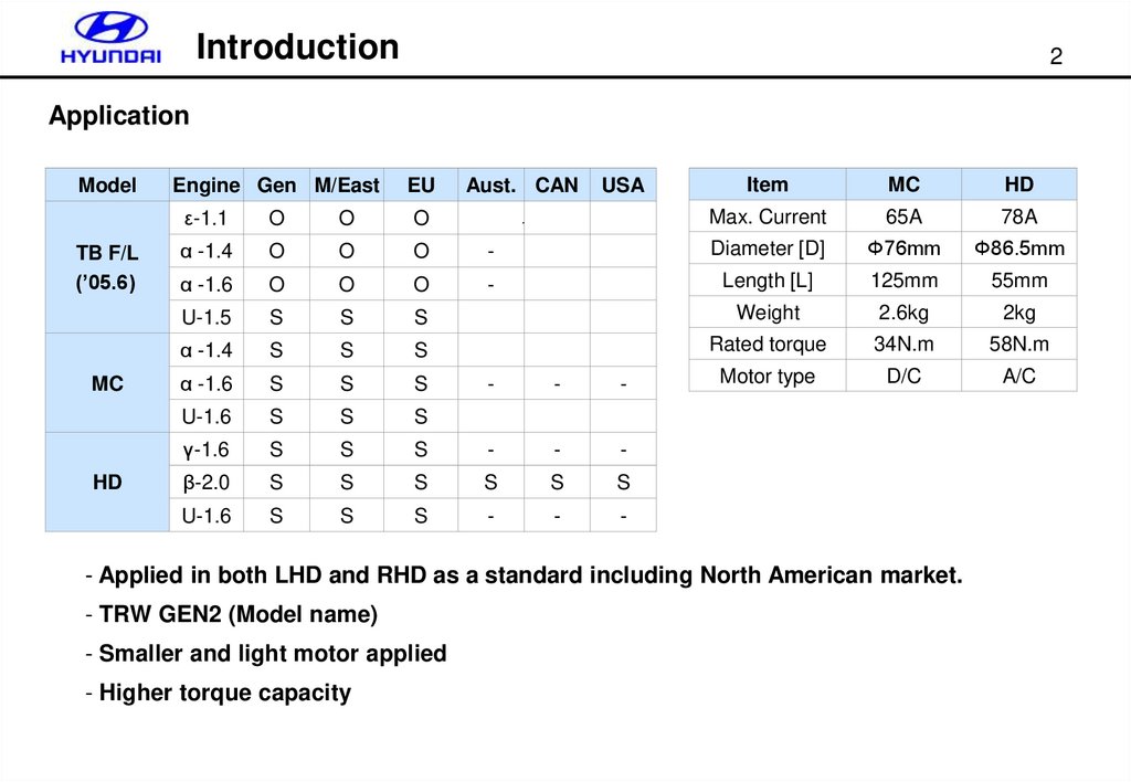
Application
Model
TB F/L
(’05.6)
MC
HD
Engine Gen M/East
EU
Aust. CAN
USA
Item
MC
HD
Max. Current
65A
78A
ε-1.1
O
O
O
α -1.4
O
O
O
-
Diameter [D]
Φ76mm
Φ86.5mm
α -1.6
O
O
O
-
Length [L]
125mm
55mm
U-1.5
S
S
S
Weight
2.6kg
2kg
α -1.4
S
S
S
Rated torque
34N.m
58N.m
α -1.6
S
S
S
Motor type
D/C
A/C
U-1.6
S
S
S
γ-1.6
S
S
β-2.0
S
U-1.6
S
-
-
-
S
-
-
-
S
S
S
S
S
S
S
-
-
-
- Applied in both LHD and RHD as a standard including North American market.
- TRW GEN2 (Model name)
- Smaller and light motor applied
- Higher torque capacity
3.
Introduction3
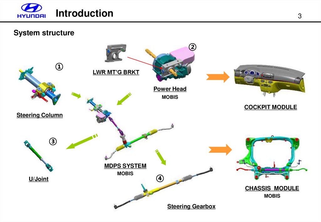
System structure
②
①
LWR MT’G BRKT
Power Head
MOBIS
COCKPIT MODULE
Steering Column
③
MDPS SYSTEM
MOBIS
U/Joint
④
CHASSIS MODULE
MOBIS
Steering Gearbox
4.
Components4
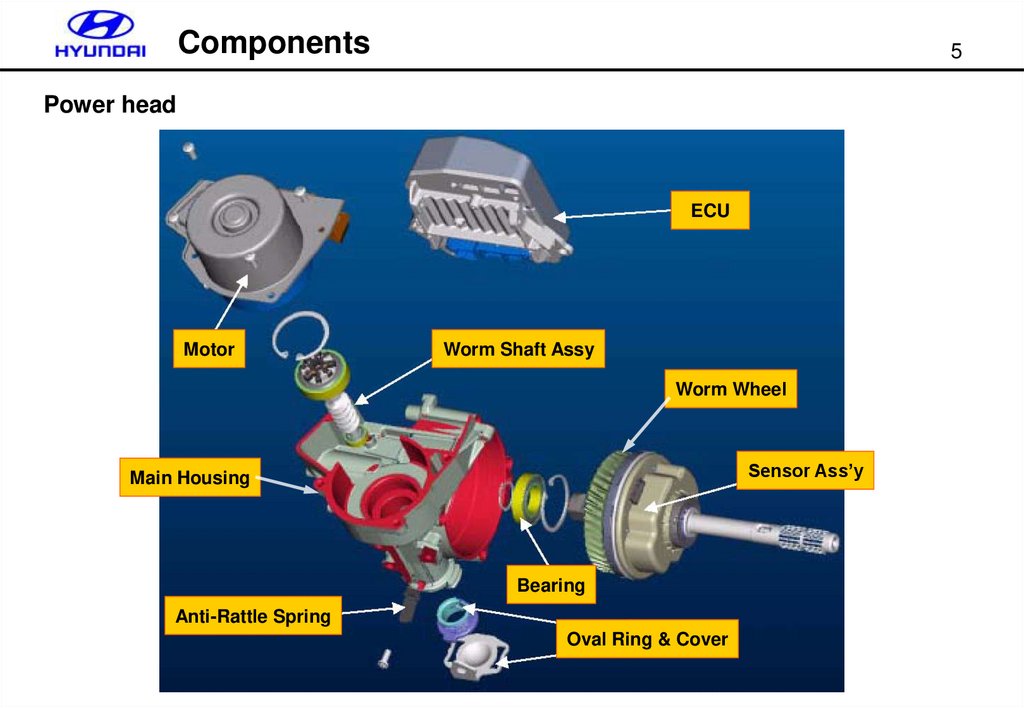
Power head
Worm Wheel
ECU
To column
To U/Joint
ASS’Y exterior
Dust Cover
Light Guide
PCB
Motor
Spring
Bearing
Worm Gear
O-Ring
Circle Lip
Bearing
Quill Shaft Ass’y
Disk
Bearing
Worm Wheel
Sensor deploy view
ASS’Y section view
5.
Components5
Power head
ECU
Motor
Worm Shaft Assy
Worm Wheel
Sensor Ass’y
Main Housing
Bearing
Anti-Rattle Spring
Oval Ring & Cover
6.
System Control6
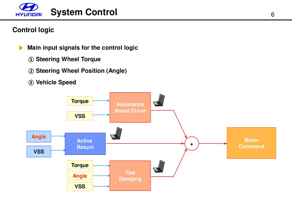
Control logic
▶ Main input signals for the control logic
① Steering Wheel Torque
② Steering Wheel Position (Angle)
③ Vehicle Speed
Torque
Assistance
Boost Curve
VSS
Angle
VSS
Active
Return
+
Torque
Angle
VSS
Yaw
Damping
Motor
Command
7.
System Control7
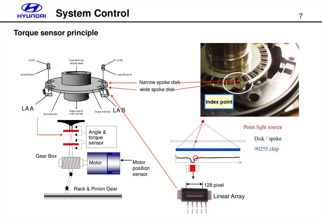
Torque sensor principle
LED A
In put sha ft fr om
ste er ing whee l
LED B
Le ns/ Diffuser A
Lens/Diff user B
Narrow spoke disk
wide spoke disk
Index point
LA A
Sensor A
Input shaft disc
Output shaft to
motor and rack
LA B
Sensor B
Ou tput shaft disc
Angle &
torque
sensor
Gear Box
Motor
Rack & Pinion Gear
Motor
position
sensor
128 pixel
Linear Array
8.
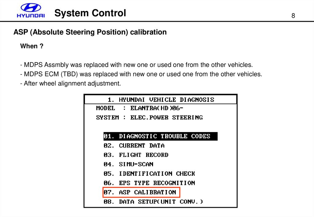
System ControlASP (Absolute Steering Position) calibration
When ?
- MDPS Assmbly was replaced with new one or used one from the other vehicles.
- MDPS ECM (TBD) was replaced with new one or used one from the other vehicles.
- After wheel alignment adjustment.
8
9.
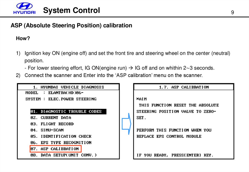
System ControlASP (Absolute Steering Position) calibration
How?
1) Ignition key ON (engine off) and set the front tire and steering wheel on the center (neutral)
position.
- For lower steering effort, IG ON(engine run) IG off and on whithin 2∼3 seconds.
2) Connect the scanner and Enter into the ‘ASP calibration’ menu on the scanner.
9
10.
System ControlASP (Absolute Steering Position) calibration
How?
3) Rotate the steering wheel more than ±180°(Left and right) from the center position
- To detect the location of index point.
4) Rotate the steering (left and right) wheel until the screen in the scanner becomes as below.
That is, if the index point is detected, the next procedure will be followed automatically.
Scanner will skip this procedure if the
index point already detected !
10
11.
System Control11
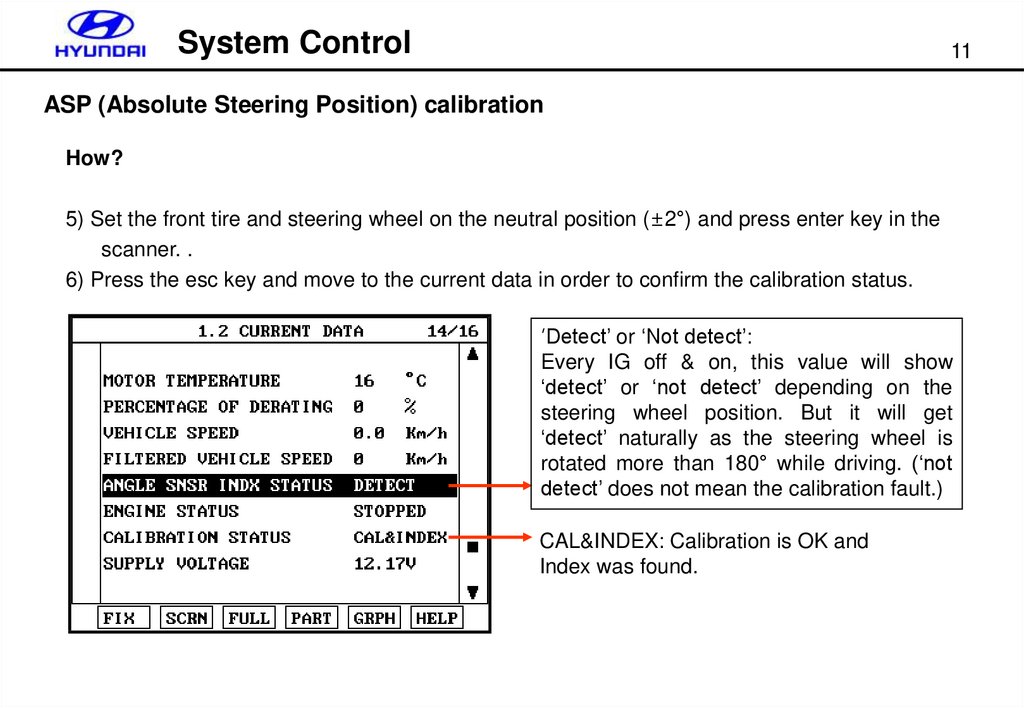
ASP (Absolute Steering Position) calibration
How?
5) Set the front tire and steering wheel on the neutral position (±2°) and press enter key in the
scanner. .
6) Press the esc key and move to the current data in order to confirm the calibration status.
‘Detect’ or ‘Not detect’:
Every IG off & on, this value will show
‘detect’ or ‘not detect’ depending on the
steering wheel position. But it will get
‘detect’ naturally as the steering wheel is
rotated more than 180° while driving. (‘not
detect’ does not mean the calibration fault.)
CAL&INDEX: Calibration is OK and
Index was found.
12.
System Control12
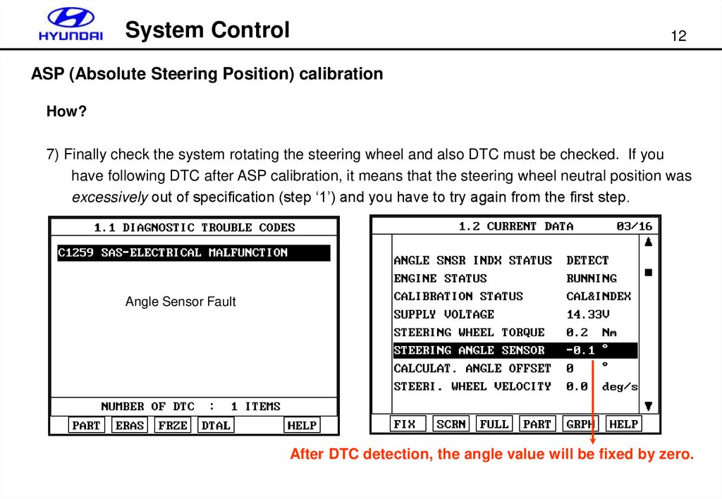
ASP (Absolute Steering Position) calibration
How?
7) Finally check the system rotating the steering wheel and also DTC must be checked. If you
have following DTC after ASP calibration, it means that the steering wheel neutral position was
excessively out of specification (step ‘1’) and you have to try again from the first step.
Angle Sensor Fault
After DTC detection, the angle value will be fixed by zero.
13.
System Control13
ASP (Absolute Steering Position) calibration
What happen if it is not done?
1) In case of replacement with new part
- Motor assist is available but warning lamp will blink and active return (on-center control) will
stop.
2) In case of replacement with used part
- Motor assist is available and warning lamp will not turn on. Active return (on-center control)
will stop.
What happen if it was done with wrong way? (improper steering wheel center position)
- You may have DTC (C1259) without warning lamp on. However, the motor assist is available
but the active return (on-center control) will stop.
14.
System Control14
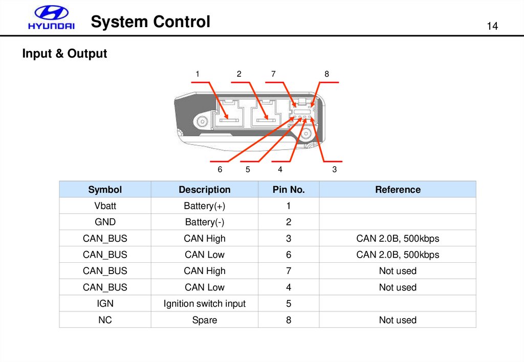
Input & Output
1
2
6
7
5
8
4
3
Symbol
Description
Pin No.
Reference
Vbatt
Battery(+)
1
GND
Battery(-)
2
CAN_BUS
CAN High
3
CAN 2.0B, 500kbps
CAN_BUS
CAN Low
6
CAN 2.0B, 500kbps
CAN_BUS
CAN High
7
Not used
CAN_BUS
CAN Low
4
Not used
IGN
Ignition switch input
5
NC
Spare
8
Not used
15.
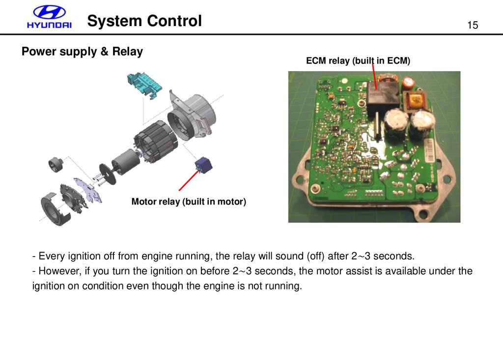
System ControlPower supply & Relay
15
ECM relay (built in ECM)
Motor relay (built in motor)
- Every ignition off from engine running, the relay will sound (off) after 2∼3 seconds.
- However, if you turn the ignition on before 2∼3 seconds, the motor assist is available under the
ignition on condition even though the engine is not running.
16.
System Control16
Overheat Protection (Derating motor current )
- Before the DTC(C1603) is detected (before the temperature reaches 85°), as soon as the
steering torque reaches to maximum value, the motor current will decrease by 40% immediately in
order to prevent the overheat in the system in advance.
17.
Diagnosis17
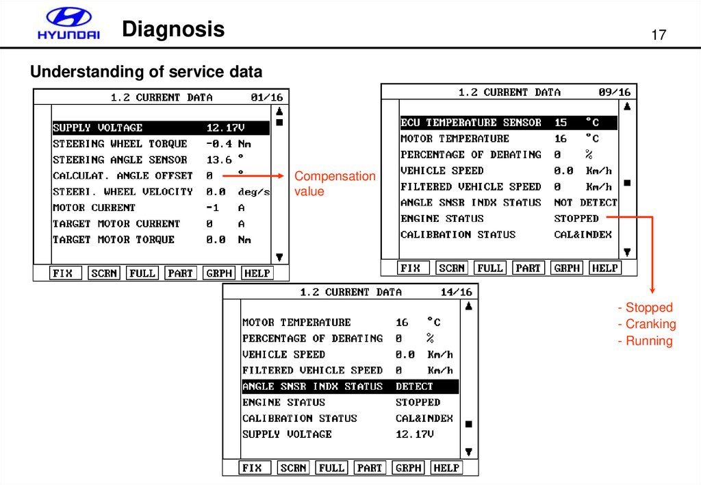
Understanding of service data
Compensation
value
- Stopped
- Cranking
- Running
18.
Diagnosis18
Failsafe for vehicle speed signal fault
- The vehicle speed signal comes from PG-B in A/T through PCM(or TCM) and CAN.
- Warning lamp OFF, No DTC and Motor ON (Default vehicle speed is 40km/h)
Normal condition
PG-B open circuit
19.
Diagnosis19
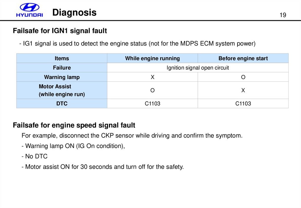
Failsafe for IGN1 signal fault
- IG1 signal is used to detect the engine status (not for the MDPS ECM system power)
Items
While engine running
Failure
Before engine start
Ignition signal open circuit
Warning lamp
X
O
Motor Assist
(while engine run)
O
X
DTC
C1103
C1103
Failsafe for engine speed signal fault
For example, disconnect the CKP sensor while driving and confirm the symptom.
- Warning lamp ON (IG On condition),
- No DTC
- Motor assist ON for 30 seconds and turn off for the safety.
20.
Diagnosis20
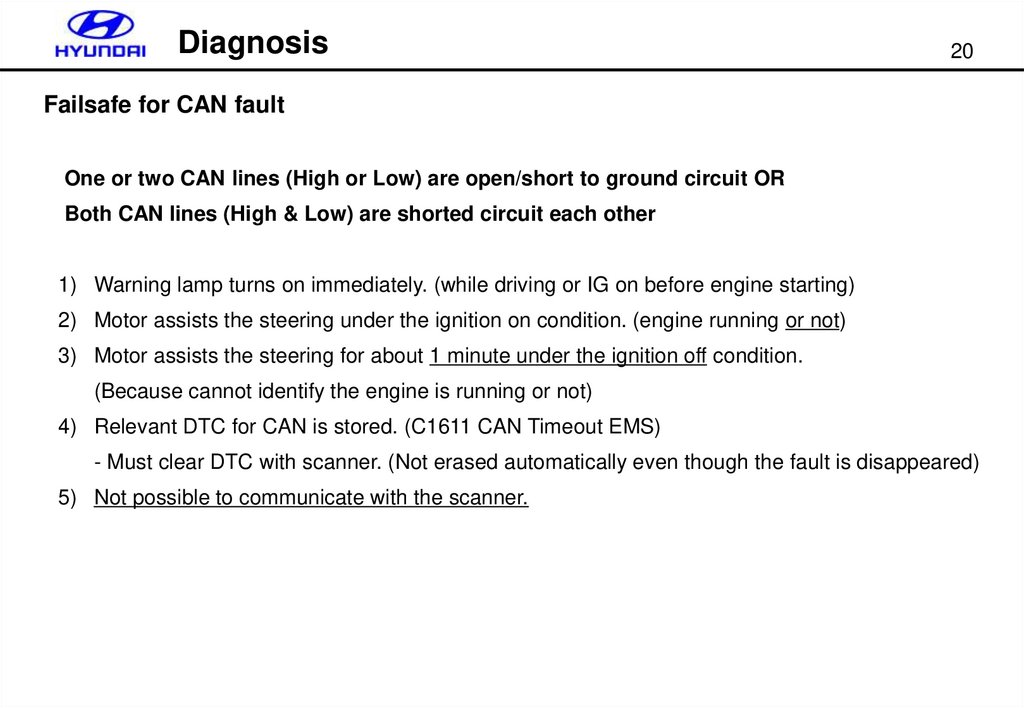
Failsafe for CAN fault
One or two CAN lines (High or Low) are open/short to ground circuit OR
Both CAN lines (High & Low) are shorted circuit each other
1) Warning lamp turns on immediately. (while driving or IG on before engine starting)
2) Motor assists the steering under the ignition on condition. (engine running or not)
3) Motor assists the steering for about 1 minute under the ignition off condition.
(Because cannot identify the engine is running or not)
4) Relevant DTC for CAN is stored. (C1611 CAN Timeout EMS)
- Must clear DTC with scanner. (Not erased automatically even though the fault is disappeared)
5) Not possible to communicate with the scanner.
21.
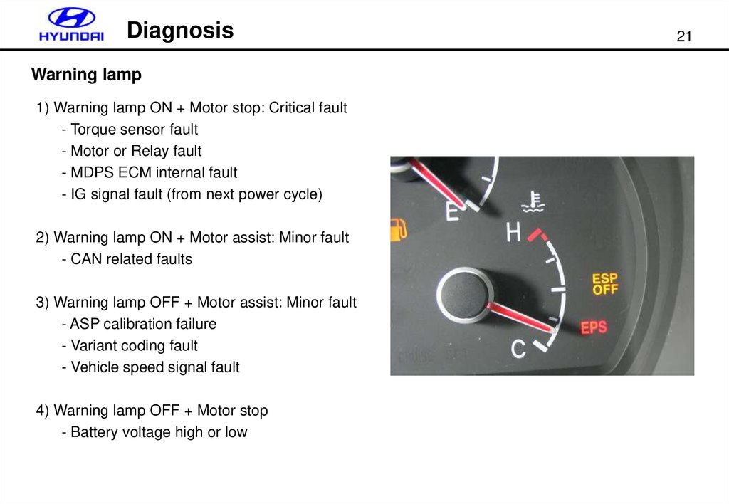
DiagnosisWarning lamp
1) Warning lamp ON + Motor stop: Critical fault
- Torque sensor fault
- Motor or Relay fault
- MDPS ECM internal fault
- IG signal fault (from next power cycle)
2) Warning lamp ON + Motor assist: Minor fault
- CAN related faults
3) Warning lamp OFF + Motor assist: Minor fault
- ASP calibration failure
- Variant coding fault
- Vehicle speed signal fault
4) Warning lamp OFF + Motor stop
- Battery voltage high or low
21
22.
Diagnosis22
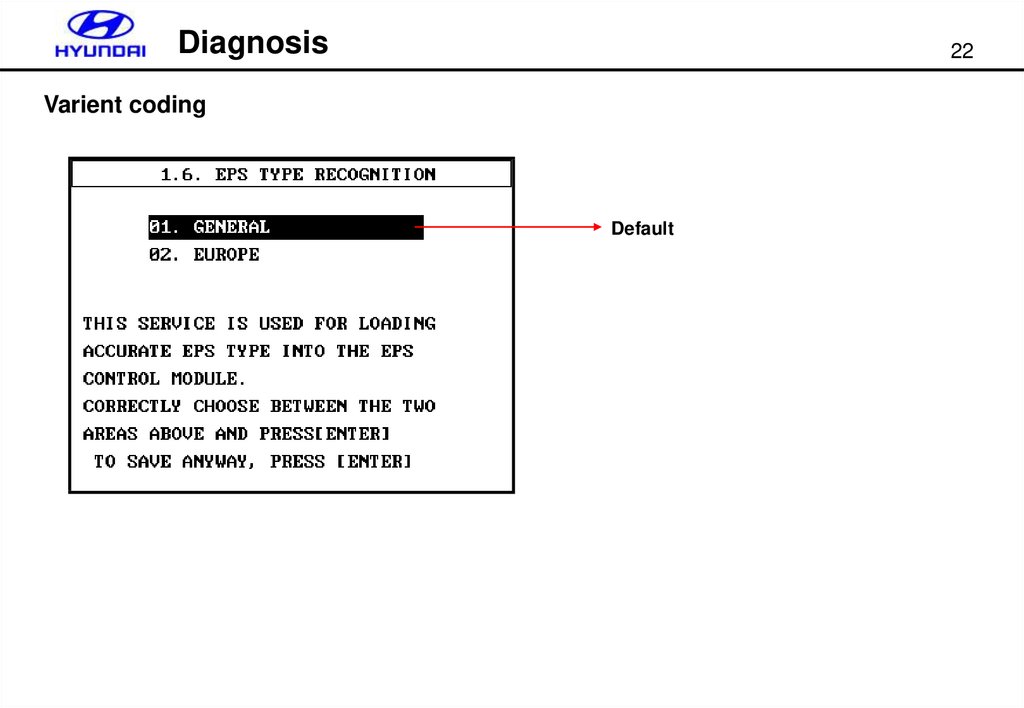
Varient coding
Default