


 Электроника
Похожие презентации:
 Application Model")

")


Components of esp system
1.
CMESP/ESC (Bosch 8)
2.
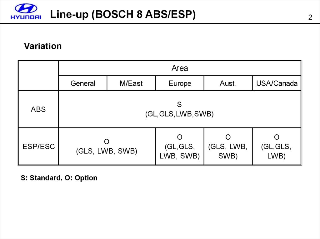
Line-up (BOSCH 8 ABS/ESP)2
Variation
Area
General
M/East
Aust.
USA/Canada
O
(GLS, LWB,
SWB)
O
(GL,GLS,
LWB)
S
(GL,GLS,LWB,SWB)
ABS
ESP/ESC
Europe
O
(GLS, LWB, SWB)
S: Standard, O: Option
O
(GL,GLS,
LWB, SWB)
3.
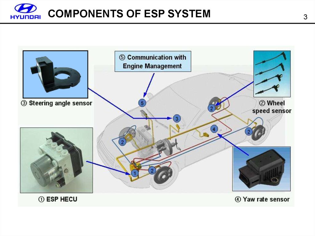
COMPONENTS OF ESP SYSTEM3
4.
VARIANT CODINGPerform the variant coding if there is a ESP OFF W/L on with a ‘C1702
(Variant Coding Error)’ after replacing a ECM,TCM or ESPCM.
4
5.
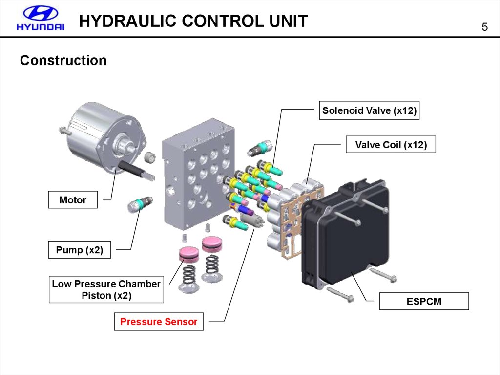
HYDRAULIC CONTROL UNIT5
Construction
Solenoid Valve (x12)
Valve Coil (x12)
Motor
Pump (x2)
Low Pressure Chamber
Piston (x2)
Pressure Sensor
ESPCM
6.
LFC (Linear Flow Control)On/Off
6
LFC Control Range
LFC
m
Pressure
Overshoot
Skid
Pressure
P
On/Off Control Range
Pressure
Undershoot
Slip
Effect of LFC (Linear Flow Control)
Prevent a pressure overshoot or undershoot Control range decrease
- Noise : Pulse-Up Noise decrease
- Enhanced Pedal Feeling
7.
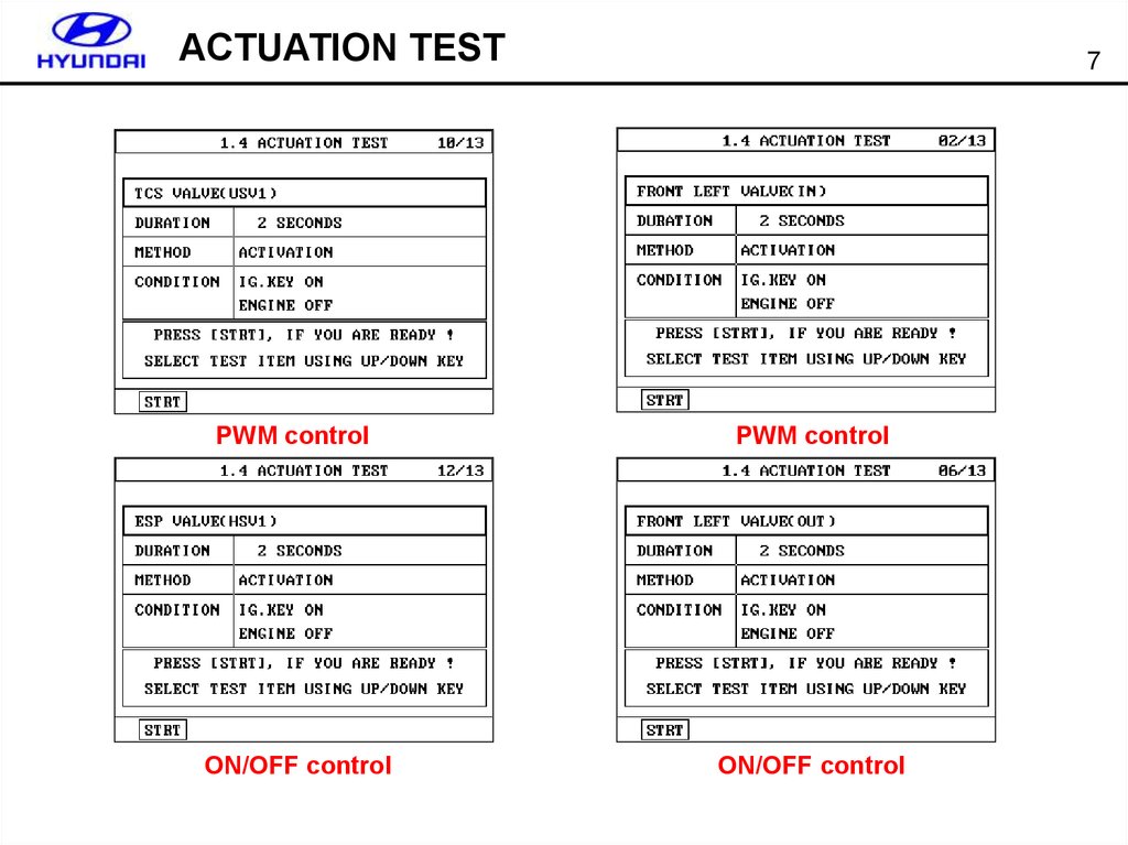
ACTUATION TEST7
PWM control
PWM control
ON/OFF control
ON/OFF control
8.
HYDRAULIC BRAKE ASSISTOperating condition
- over 30 bar
- over 2,200 bar/sec
- over 20 km/h
Pressure sensor
HECU
8
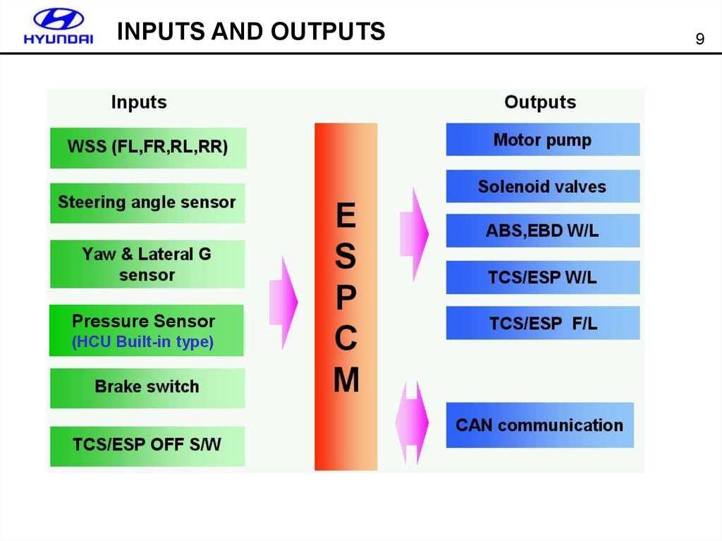
9.
INPUTS AND OUTPUTSPressure Sensor
(HCU Built-in type)
9
10.
ACTIVE WHEEL SPEED SENSOR10
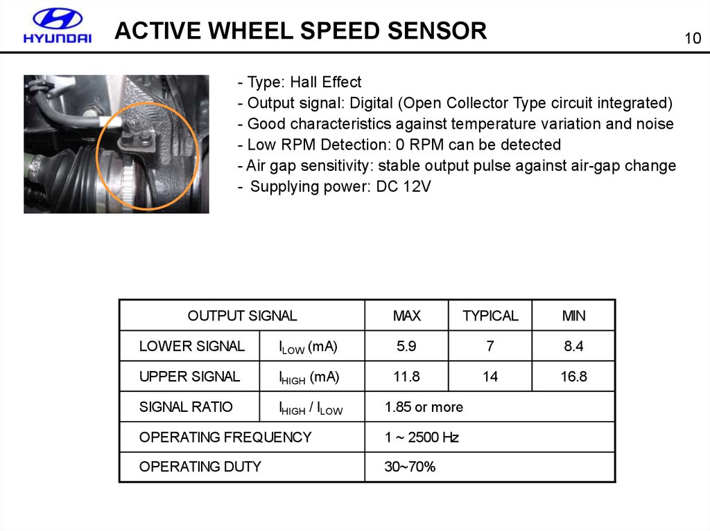
- Type: Hall Effect
- Output signal: Digital (Open Collector Type circuit integrated)
- Good characteristics against temperature variation and noise
- Low RPM Detection: 0 RPM can be detected
- Air gap sensitivity: stable output pulse against air-gap change
- Supplying power: DC 12V
OUTPUT SIGNAL
MAX
TYPICAL
MIN
LOWER SIGNAL
ILOW (mA)
5.9
7
8.4
UPPER SIGNAL
IHIGH (mA)
11.8
14
16.8
SIGNAL RATIO
IHIGH / ILOW
1.85 or more
OPERATING FREQUENCY
1 ~ 2500 Hz
OPERATING DUTY
30~70%
11.
ACTIVE WHEEL SPEED SENSOR11
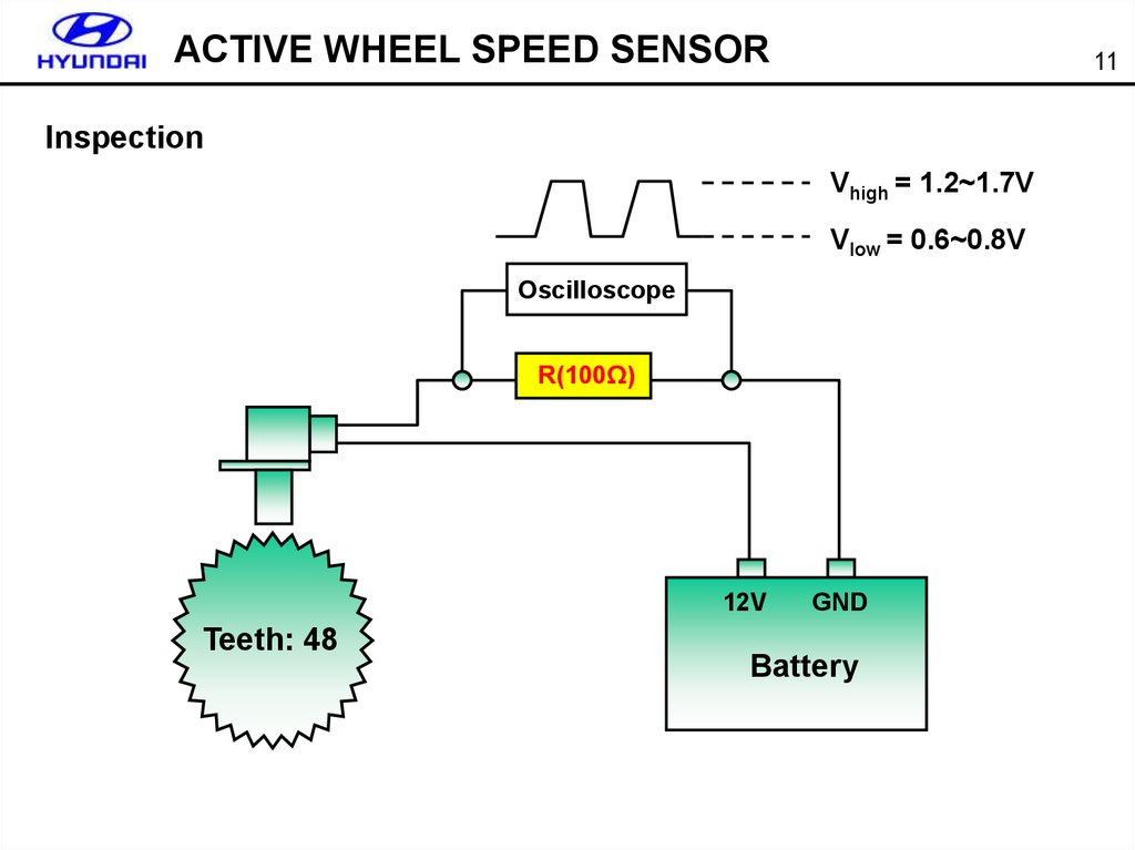
Inspection
Vhigh = 1.2~1.7V
Vlow = 0.6~0.8V
Oscilloscope
R(100Ω)
12V
Teeth: 48
GND
Battery
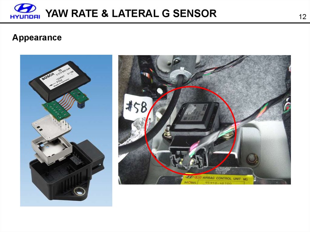
12.
YAW RATE & LATERAL G SENSORAppearance
12
13.
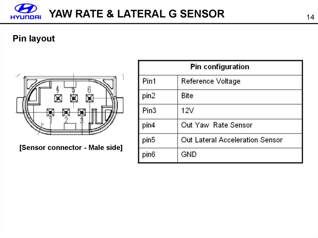
YAW RATE & LATERAL G SENSORPin layout
[Sensor connector - Male side]
14
14.
YAW RATE & LATERAL G SENSOR15
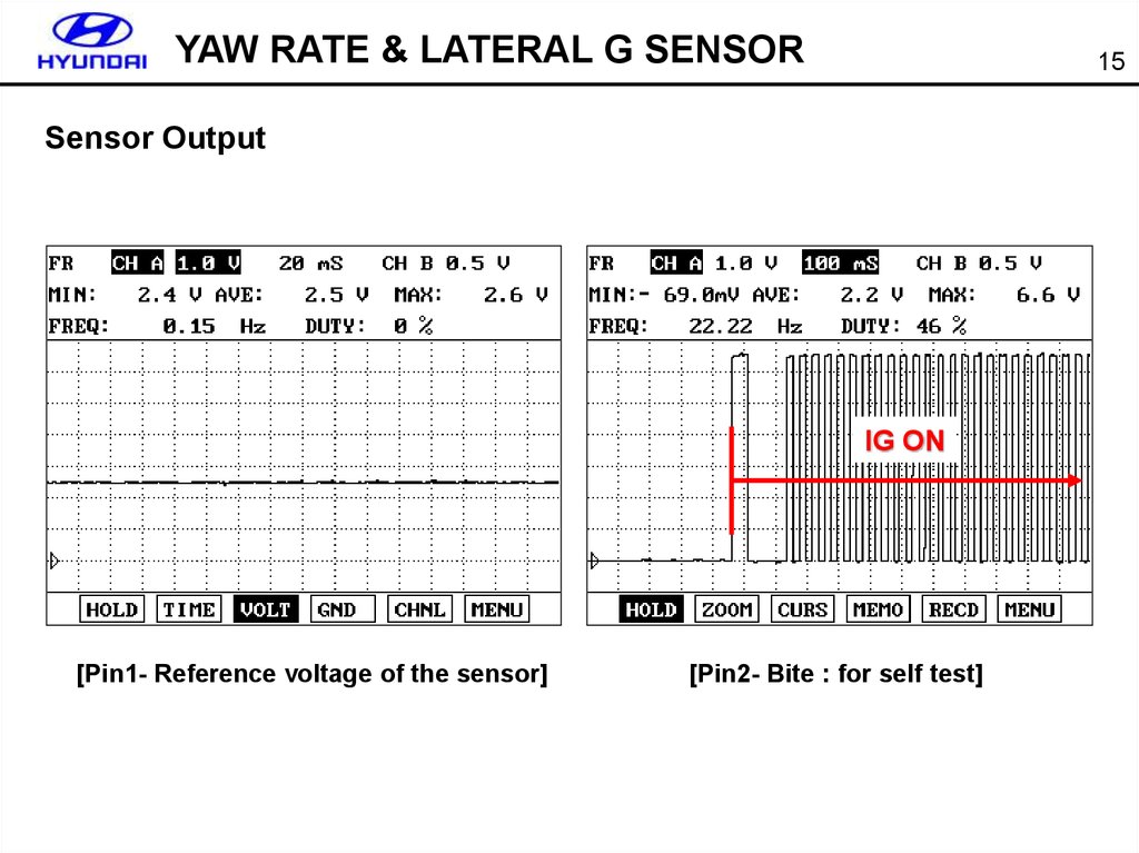
Sensor Output
IG ON
[Pin1- Reference voltage of the sensor]
[Pin2- Bite : for self test]
15.
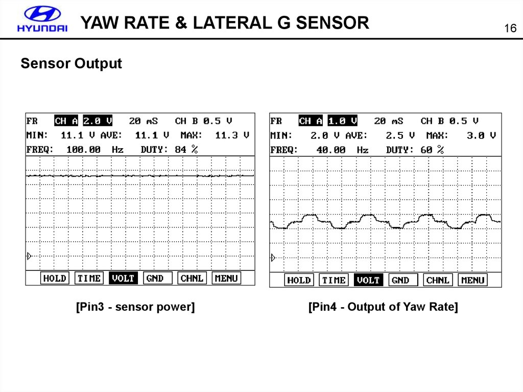
YAW RATE & LATERAL G SENSORSensor Output
[Pin3 - sensor power]
[Pin4 - Output of Yaw Rate]
16
16.
YAW RATE & LATERAL G SENSORSensor Output
[Pin5 - Lateral G sensor output]
[Lateral G sensor output: 90˚ to the right]
17
17.
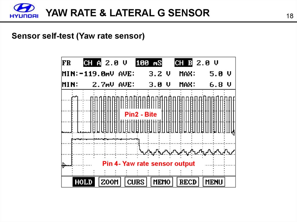
YAW RATE & LATERAL G SENSORSensor self-test (Yaw rate sensor)
Pin2 - Bite
Pin 4- Yaw rate sensor output
18
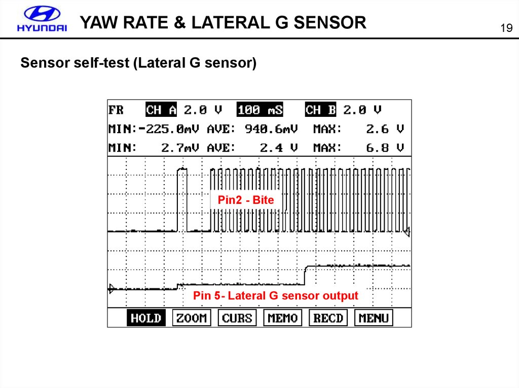
18.
YAW RATE & LATERAL G SENSORSensor self-test (Lateral G sensor)
Pin2 - Bite
Pin 5- Lateral G sensor output
19
19.
YAW RATE & LATERAL G SENSORCurrent data & DTC
20
20.
YAW RATE & LATERAL G SENSORCurrent data & DTC
C1282 (Reference voltage/Yaw/Lateral G Sensor short to GND)
21
21.
YAW RATE & LATERAL G SENSORCurrent data & DTC
C1283 (BITE short to GND)
22
22.
YAW RATE & LATERAL G SENSORCurrent data & DTC
Lateral G sensor output
[When the BITE is normal]
[When the BITE(Pin2) short to GND]
23
23.
YAW RATE & LATERAL G SENSORCurrent data & DTC
Yaw rate sensor output
2.5V without wave pattern
[When the BITE is normal]
[When the BITE(Pin2) short to GND]
24
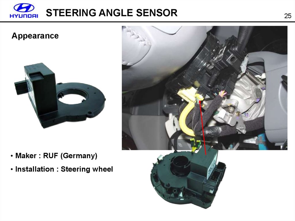
24.
STEERING ANGLE SENSORAppearance
• Maker : RUF (Germany)
• Installation : Steering wheel
25
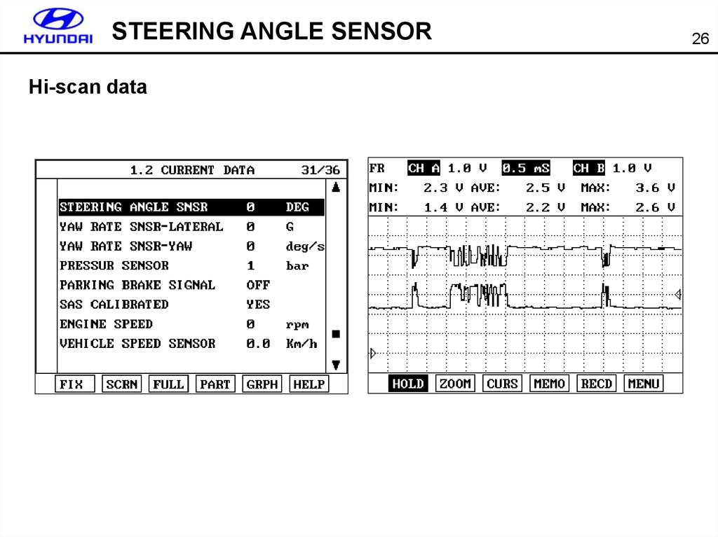
25.
STEERING ANGLE SENSORHi-scan data
26
26.
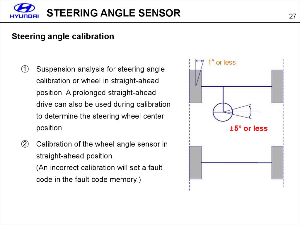
STEERING ANGLE SENSOR27
Steering angle calibration
①
Suspension analysis for steering angle
calibration or wheel in straight-ahead
position. A prolonged straight-ahead
drive can also be used during calibration
to determine the steering wheel center
position.
②
Calibration of the wheel angle sensor in
straight-ahead position.
(An incorrect calibration will set a fault
code in the fault code memory.)
±5° or less
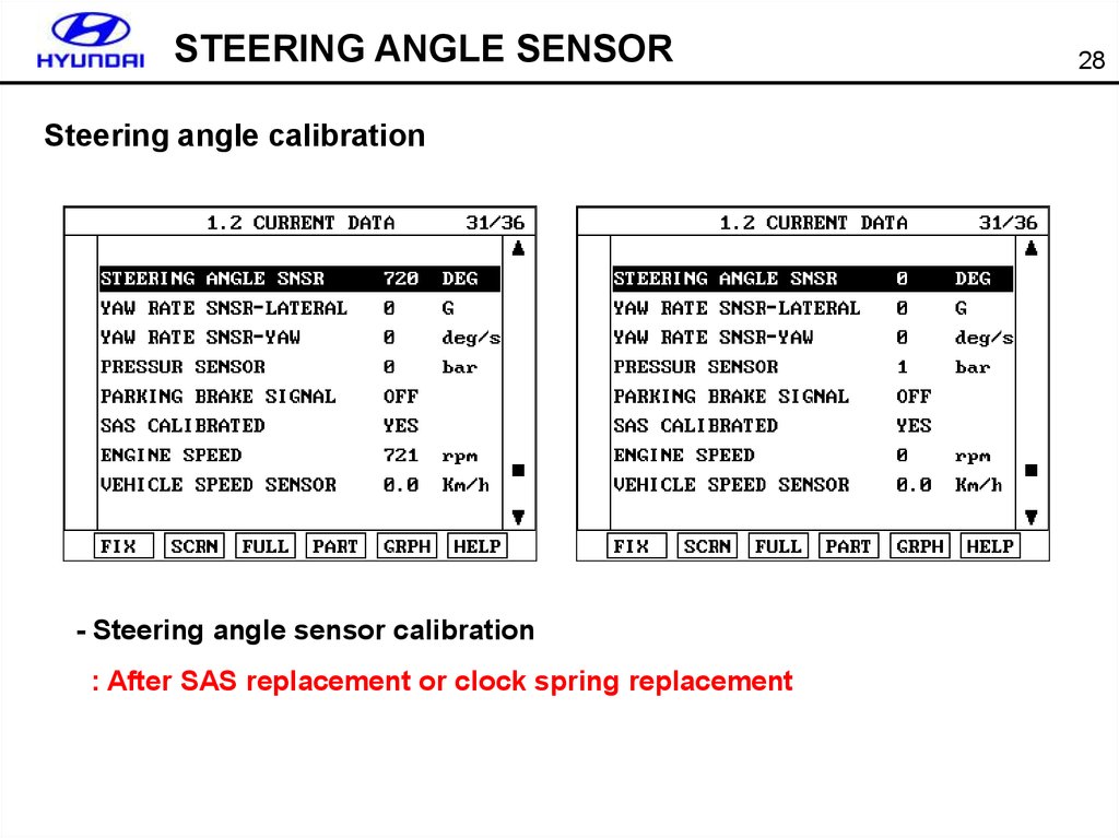
27.
STEERING ANGLE SENSORSteering angle calibration
- Steering angle sensor calibration
: After SAS replacement or clock spring replacement
28
28.
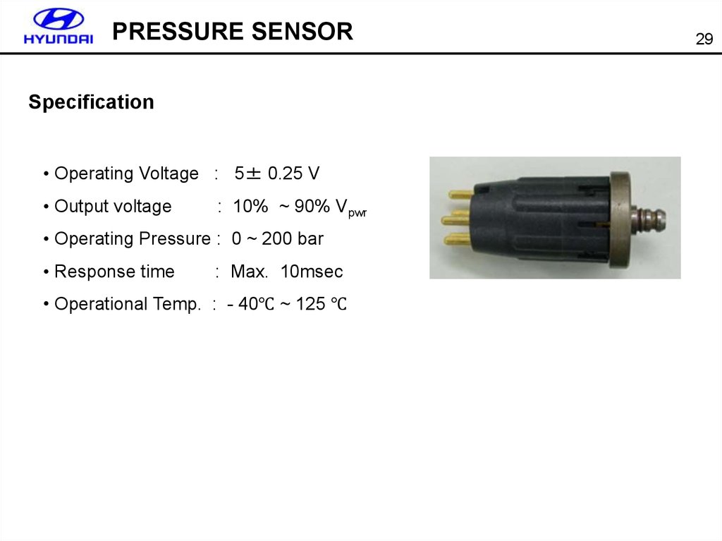
PRESSURE SENSORSpecification
• Operating Voltage : 5± 0.25 V
• Output voltage
: 10% ~ 90% Vpwr
• Operating Pressure : 0 ~ 200 bar
• Response time
: Max. 10msec
• Operational Temp. : - 40℃ ~ 125 ℃
29