


 Электроника
Похожие презентации:


 - Technical Highlights")


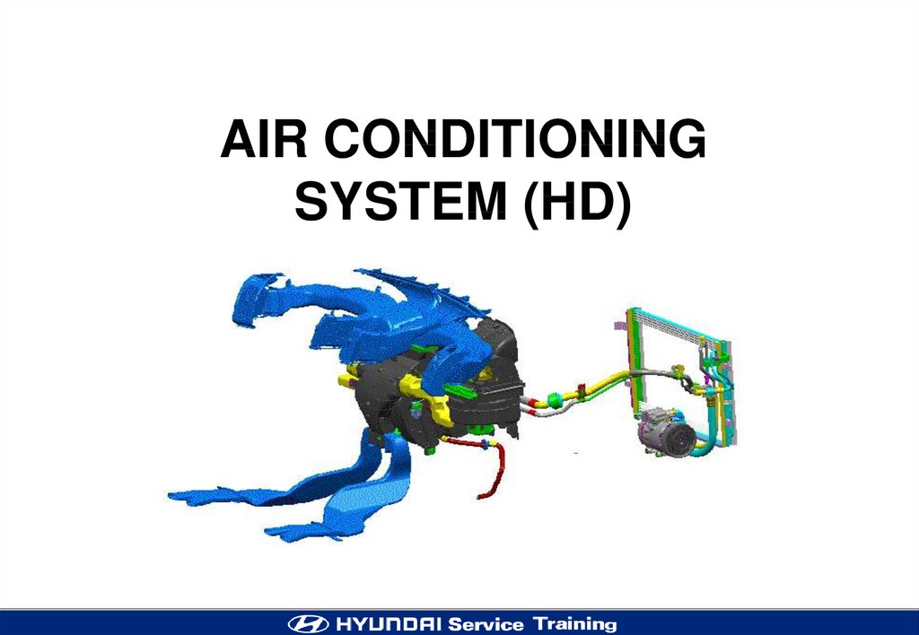
Air conditioning system (HD)
1.
AIR CONDITIONINGSYSTEM (HD)
2.
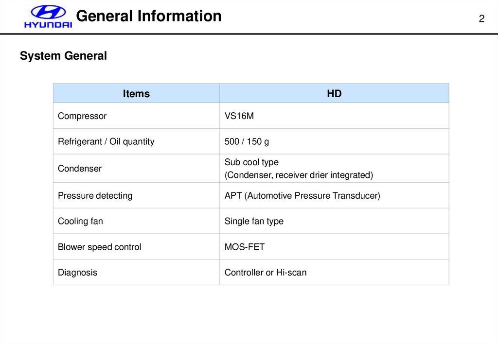
General Information2
System General
Items
HD
Compressor
VS16M
Refrigerant / Oil quantity
500 / 150 g
Condenser
Sub cool type
(Condenser, receiver drier integrated)
Pressure detecting
APT (Automotive Pressure Transducer)
Cooling fan
Single fan type
Blower speed control
MOS-FET
Diagnosis
Controller or Hi-scan
3.
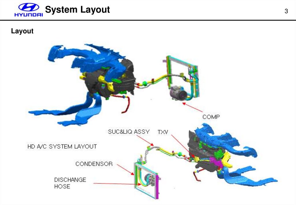
System LayoutLayout
3
4.
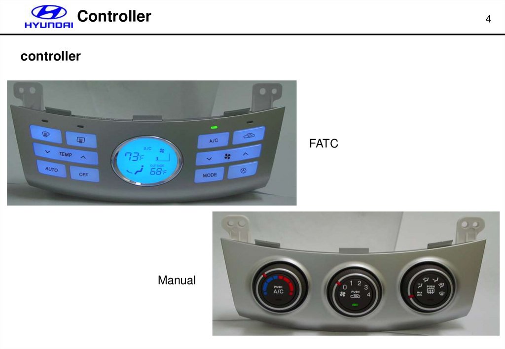
Controller4
controller
FATC
Manual
5.
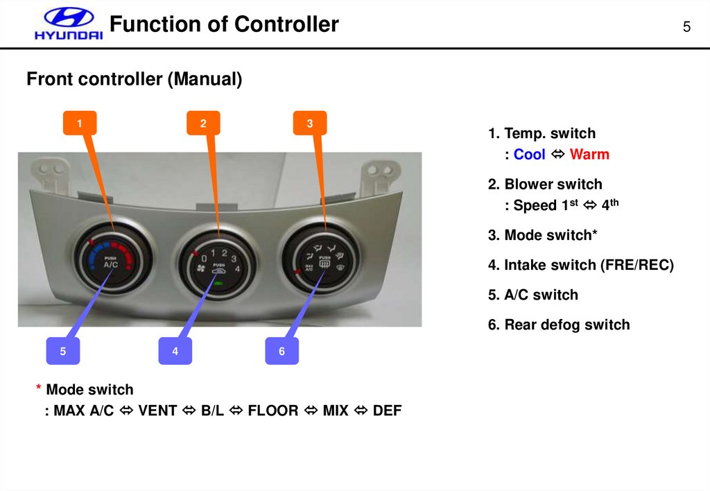
Function of Controller5
Front controller (Manual)
1
2
3
1. Temp. switch
: Cool Warm
2. Blower switch
: Speed 1st 4th
3. Mode switch*
4. Intake switch (FRE/REC)
5. A/C switch
6. Rear defog switch
5
4
6
* Mode switch
: MAX A/C VENT B/L FLOOR MIX DEF
6.
Function of Controller6
Controller (Auto)
1. DEF. switch
2. Rear Defog switch
1
3
2
4
3. A/C switch : REC fixed
4. Recirculation switch
5. Temp. switch
: 63℉(17.5 ℃)∼89℉(31.5 ℃),
up/down by 1℉(0.5℃)
6. Auto switch
: Temp.,blower,mode,
A/C,Intake control
5
6
7
8
9
10
7. Off switch
: Blower off, A/C off
(MODE, AQS, REC available)
* Mode switch
: VENT B/L FLOOR MIX VENT
8. Mode switch*
9. AQS switch : FRE/REC changed by air
status
10. Blower switch : 8 step control
7.
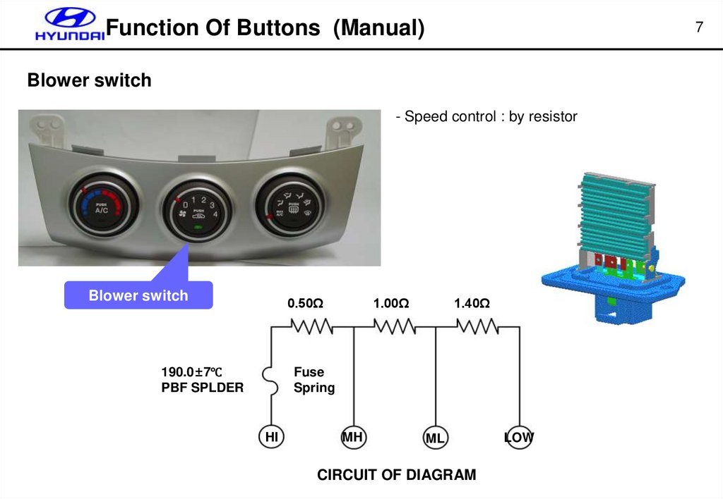
Function Of Buttons (Manual)7
Blower switch
- Speed control : by resistor
Blower switch
0.50Ω
1.40Ω
1.00Ω
Fuse
Spring
190.0±7℃
PBF SPLDER
HI
MH
ML
CIRCUIT OF DIAGRAM
LOW
8.
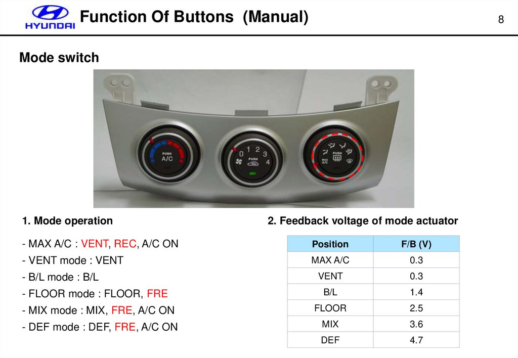
Function Of Buttons (Manual)8
Mode switch
1. Mode operation
2. Feedback voltage of mode actuator
- MAX A/C : VENT, REC, A/C ON
Position
F/B (V)
- VENT mode : VENT
MAX A/C
0.3
VENT
0.3
B/L
1.4
- MIX mode : MIX, FRE, A/C ON
FLOOR
2.5
- DEF mode : DEF, FRE, A/C ON
MIX
3.6
DEF
4.7
- B/L mode : B/L
- FLOOR mode : FLOOR, FRE
9.
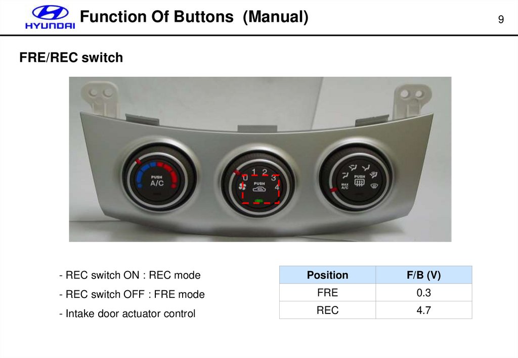
Function Of Buttons (Manual)9
FRE/REC switch
- REC switch ON : REC mode
Position
F/B (V)
- REC switch OFF : FRE mode
FRE
0.3
- Intake door actuator control
REC
4.7
10.
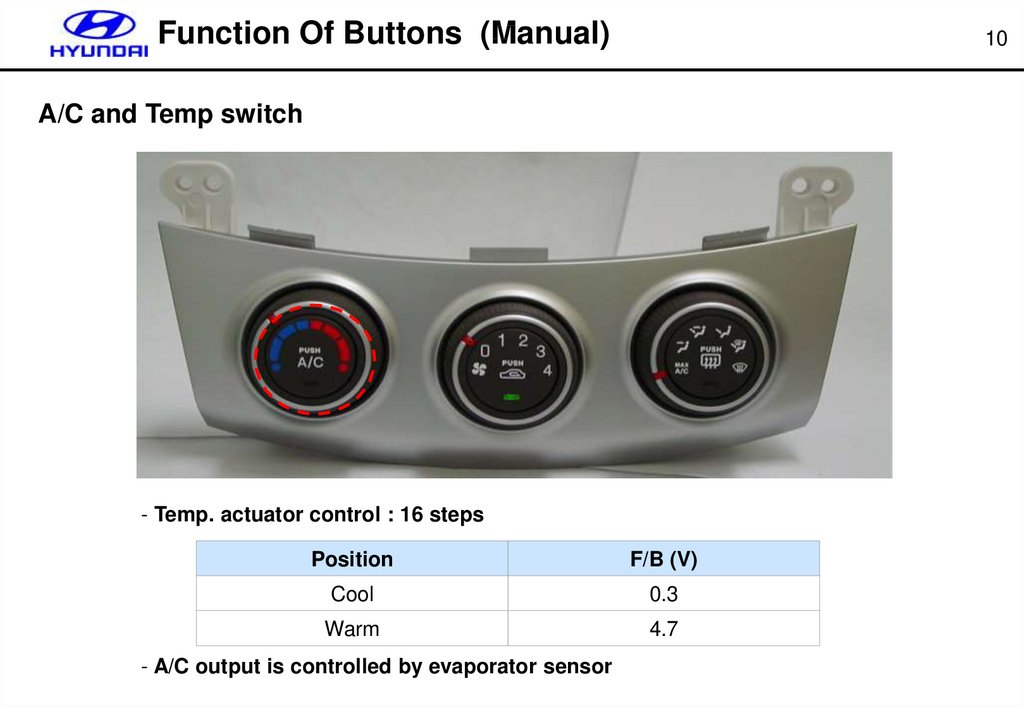
Function Of Buttons (Manual)10
A/C and Temp switch
- Temp. actuator control : 16 steps
Position
F/B (V)
Cool
0.3
Warm
4.7
- A/C output is controlled by evaporator sensor
11.
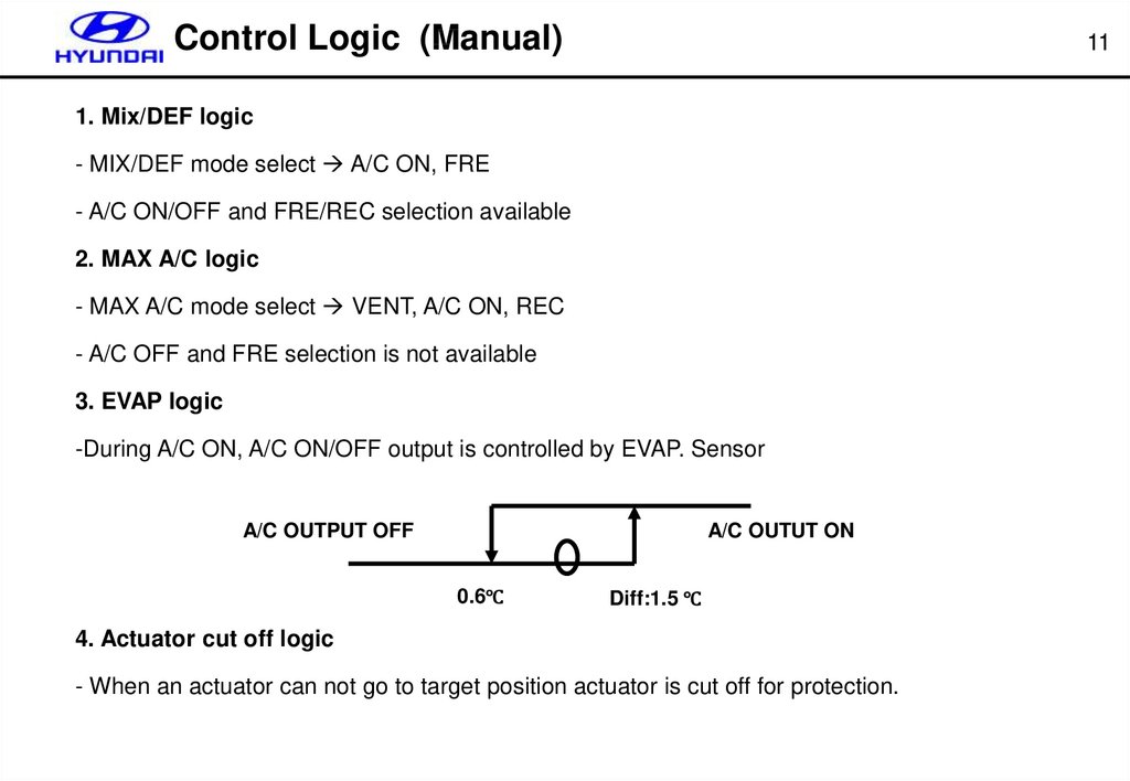
Control Logic (Manual)11
1. Mix/DEF logic
- MIX/DEF mode select A/C ON, FRE
- A/C ON/OFF and FRE/REC selection available
2. MAX A/C logic
- MAX A/C mode select VENT, A/C ON, REC
- A/C OFF and FRE selection is not available
3. EVAP logic
-During A/C ON, A/C ON/OFF output is controlled by EVAP. Sensor
A/C OUTPUT OFF
A/C OUTUT ON
0.6℃
Diff:1.5 ℃
4. Actuator cut off logic
- When an actuator can not go to target position actuator is cut off for protection.
12.
Control Logic (Manual)Logic cancel & selection
① Select DEF mode
② Push REC button 5 times for 3 seconds
③ See REC indicator flashes 3 times with 2Hz.
④ Logic cancel & selection
- Logic cancel : initialized by A/C OFF, FRE
- Logic re-selected (at DEF mode) : initialized by A/C ON (indicator ON), FRE
12
13.
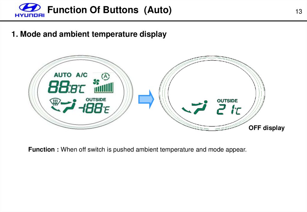
Function Of Buttons (Auto)13
1. Mode and ambient temperature display
OFF display
Function : When off switch is pushed ambient temperature and mode appear.
14.
Function Of Buttons (Auto)2. DEF mode control
DEF mode operation
- mode door : DEF position
- intake door : FRE position (REC selectable)
- A/C : on
- prior to MAX COOL/HOT function
3. OFF switch
System operation
- blower speed : off
- temp door : move to cool position after 20 sec delayed
- A/C : off
- intake door : FRE
- AQS function : off
14
15.
Function Of Buttons (Auto)4. AQS control
System operation
- Select the DEF during AQS ON : DEF is prior to AQS
- MAX cool/hot is prior to AQS
- When a preheating AQS : FRE position
15
16.
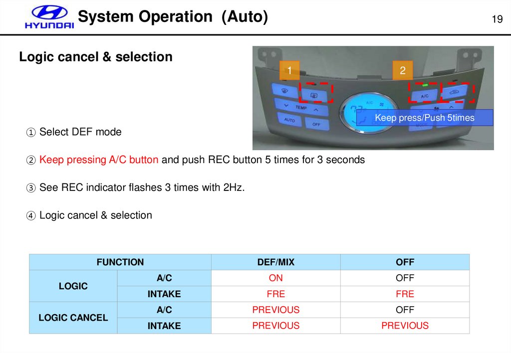
System Operation (Auto)19
Logic cancel & selection
1
2
Keep press/Push 5times
① Select DEF mode
② Keep pressing A/C button and push REC button 5 times for 3 seconds
③ See REC indicator flashes 3 times with 2Hz.
④ Logic cancel & selection
FUNCTION
LOGIC
LOGIC CANCEL
DEF/MIX
OFF
A/C
ON
OFF
INTAKE
FRE
FRE
A/C
PREVIOUS
OFF
INTAKE
PREVIOUS
PREVIOUS
17.
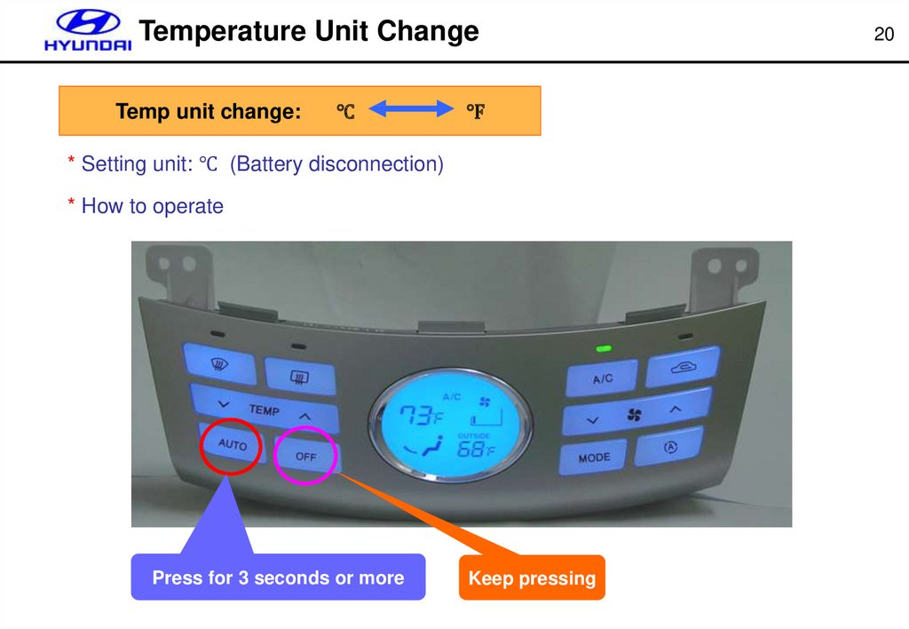
Temperature Unit ChangeTemp unit change:
℃
℉
* Setting unit: ℃ (Battery disconnection)
* How to operate
Press for 3 seconds or more
Keep pressing
20
18.
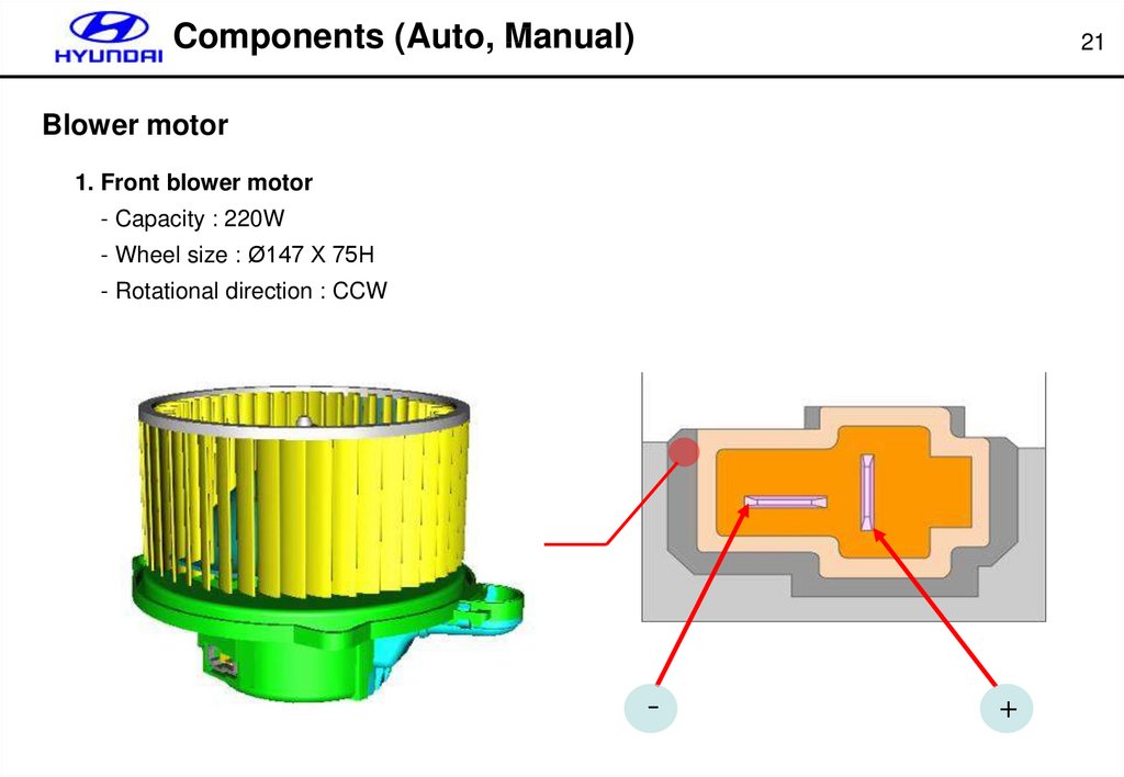
Components (Auto, Manual)21
Blower motor
1. Front blower motor
- Capacity : 220W
- Wheel size : Ø147 X 75H
- Rotational direction : CCW
-
+
19.
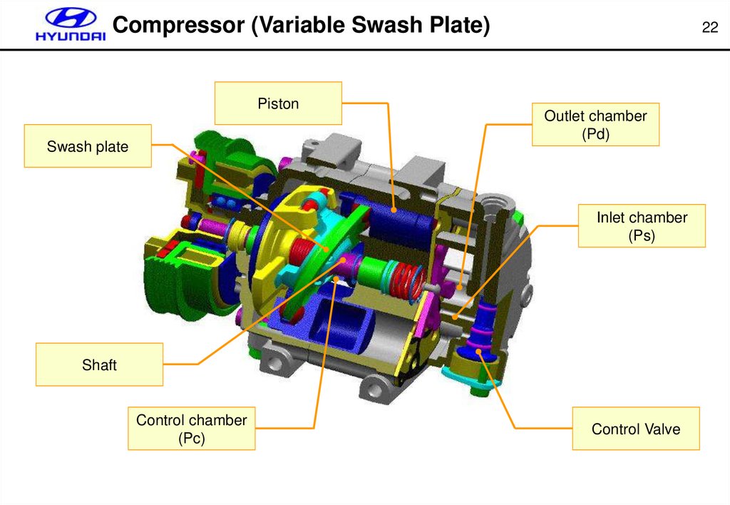
Compressor (Variable Swash Plate)Piston
Swash plate
22
Outlet chamber
(Pd)
Inlet chamber
(Ps)
Shaft
Control chamber
(Pc)
Control Valve
20.
Components (Auto, Manual)23
HVAC (Heating, Ventilation and Air Conditioning)
MODE ACTUATOR
EVAP SENSOR
CONNECTOR
WATER TEMP
SENSOR
(FATC ONLY)
HEATER CORE
TEMP ACTUATOR
21.
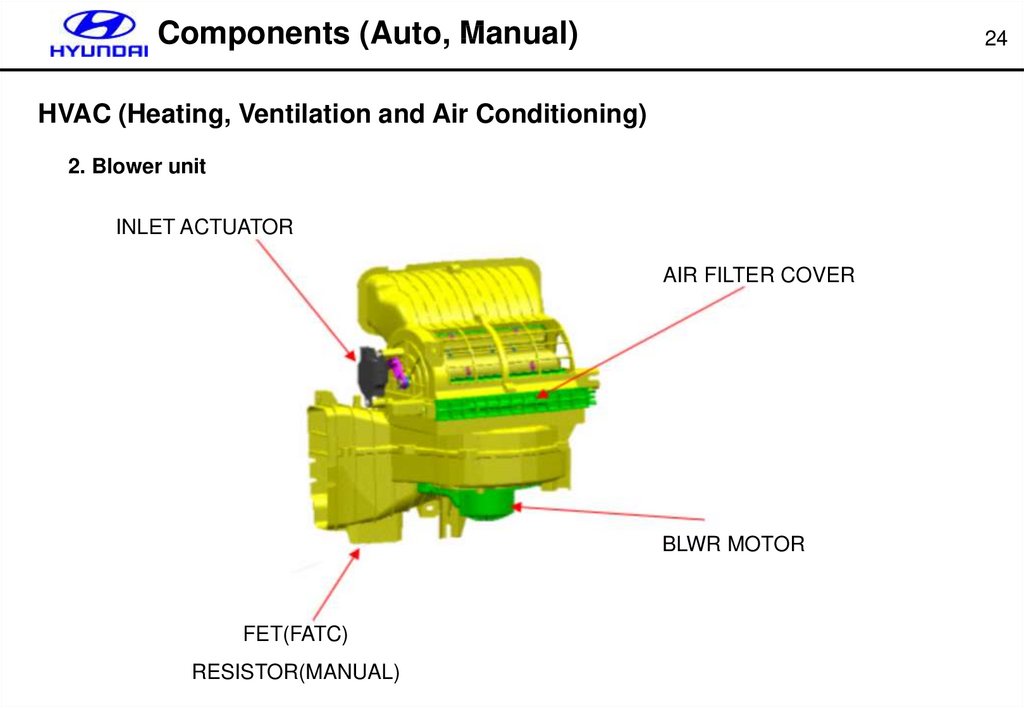
Components (Auto, Manual)24
HVAC (Heating, Ventilation and Air Conditioning)
2. Blower unit
INLET ACTUATOR
AIR FILTER COVER
BLWR MOTOR
FET(FATC)
RESISTOR(MANUAL)
22.
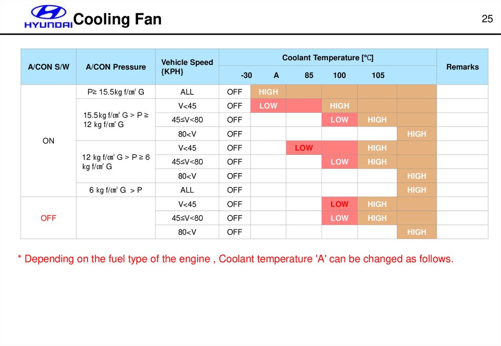
Cooling FanA/CON S/W
A/CON Pressure
P≥ 15.5㎏ f/㎠ G
15.5㎏ f/㎠ G > P ≥
12 ㎏ f/㎠ G
ON
12 ㎏ f/㎠ G > P ≥ 6
㎏ f/㎠ G
6 ㎏ f/㎠ G > P
OFF
25
Vehicle Speed
{KPH}
Coolant Temperature [℃]
Remarks
-30
A
85
100
105
ALL
OFF
HIGH
V<45
OFF
LOW
45≤V<80
OFF
80<V
OFF
V<45
OFF
45≤V<80
OFF
80<V
OFF
HIGH
ALL
OFF
HIGH
V<45
OFF
LOW
HIGH
45≤V<80
OFF
LOW
HIGH
80<V
OFF
HIGH
LOW
HIGH
HIGH
LOW
HIGH
LOW
HIGH
HIGH
* Depending on the fuel type of the engine , Coolant temperature 'A' can be changed as follows.
23.
Components (Auto)26
MOS FET (Metal Oxide Semiconductor Field Effect Transistor)
Blower
Vm
motor
Drain
FET ass’y
HTR control
Vds
FATC / Manual
Blower speed
Vm
1st
3.8 V
2nd
4.9 V
3rd
6.1 V
4th
7.2 V
5th
8.3 V
Pin
Function
6th
9.5 V
1
Drain
7th
10.6 V
2
Source
8th
Batt
3
Gate
Source
Gate
24.
Components (Auto, Manual)30
APT (Automotive Pressure Transducer)
1. Specification
- Supply voltage : 5.0V
- Operating temp. : -40℃ ~ 135℃
- Pressure range : 0 ~ 32 Kgf/㎠
2. Characteristics
OUTPUT (Vdc)
Approximately 4.8V
Approximately
0.2V
1.0
Normal
Operating range
32.6
Pressure (kg/ ㎠)
25.
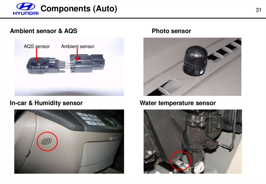
Components (Auto)Ambient sensor & AQS
AQS sensor
31
Photo sensor
Ambient sensor
In-car & Humidity sensor
Water temperature sensor
26.
PTC Heater32
HEATER CORE
VENT DOOR
DEF DOOR
FOOT DOOR
Fresch air
EVAPORATOR
PTC HEATER
Heater core with
PTC heater
27.
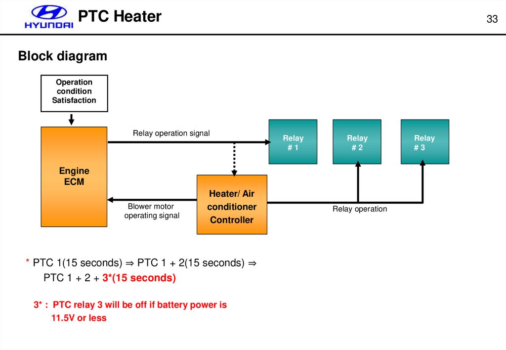
PTC Heater33
Block diagram
Operation
condition
Satisfaction
Relay operation signal
Relay
#1
Relay
#2
Engine
ECM
Blower motor
operating signal
Heater/ Air
conditioner
Controller
* PTC 1(15 seconds) ⇒ PTC 1 + 2(15 seconds) ⇒
PTC 1 + 2 + 3*(15 seconds)
3* : PTC relay 3 will be off if battery power is
11.5V or less
Relay operation
Relay
#3
28.
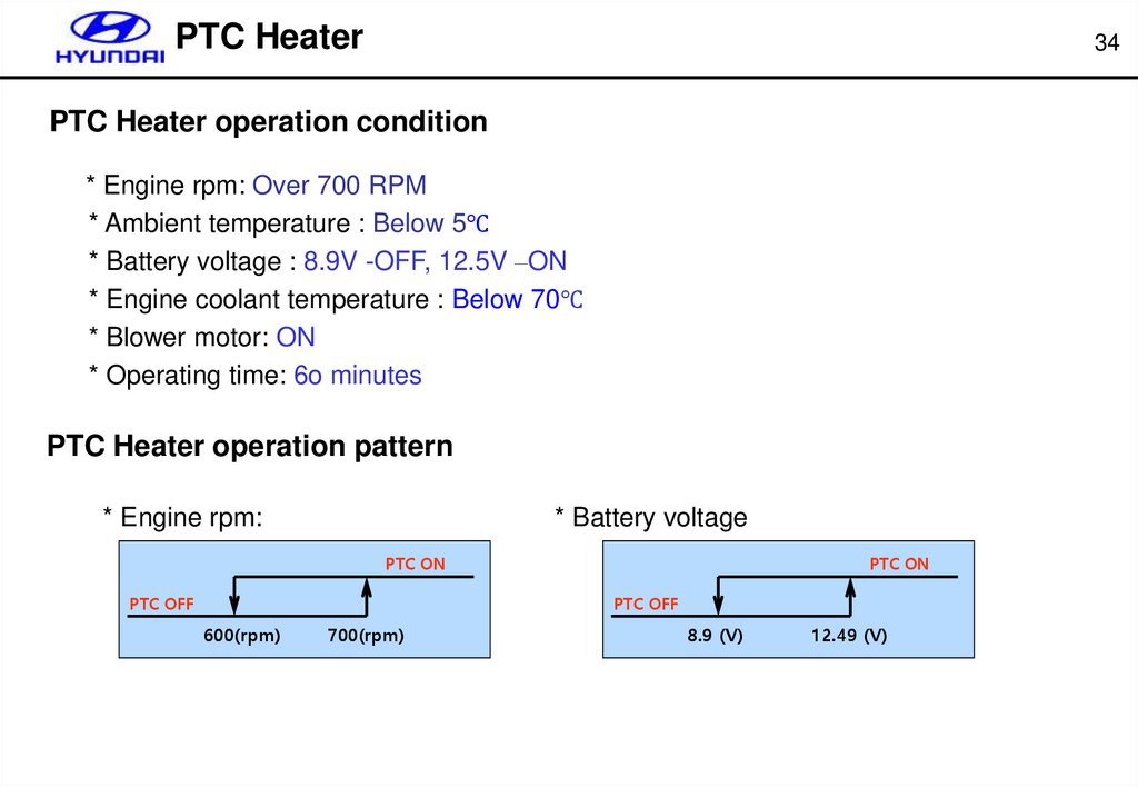
PTC Heater34
PTC Heater operation condition
* Engine rpm: Over 700 RPM
* Ambient temperature : Below 5℃
* Battery voltage : 8.9V -OFF, 12.5V –ON
* Engine coolant temperature : Below 70℃
* Blower motor: ON
* Operating time: 6o minutes
PTC Heater operation pattern
* Engine rpm:
* Battery voltage
PTC ON
PTC OFF
PTC ON
PTC OFF
600(rpm)
700(rpm)
8.9 (V)
12.49 (V)
29.
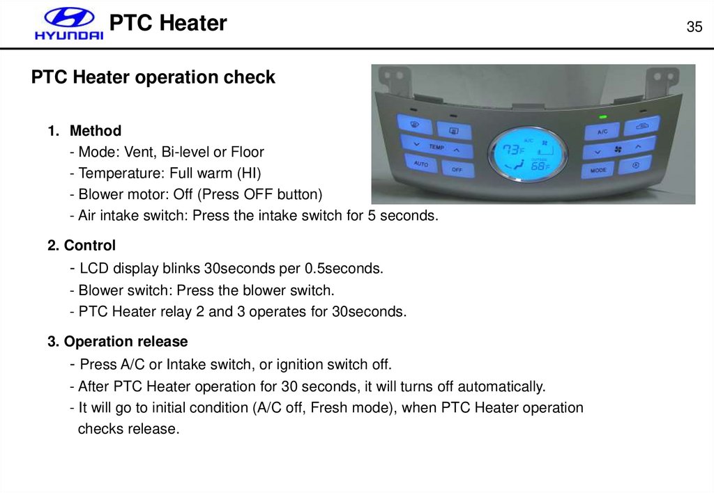
PTC HeaterPTC Heater operation check
1. Method
- Mode: Vent, Bi-level or Floor
- Temperature: Full warm (HI)
- Blower motor: Off (Press OFF button)
- Air intake switch: Press the intake switch for 5 seconds.
2. Control
- LCD display blinks 30seconds per 0.5seconds.
- Blower switch: Press the blower switch.
- PTC Heater relay 2 and 3 operates for 30seconds.
3. Operation release
- Press A/C or Intake switch, or ignition switch off.
- After PTC Heater operation for 30 seconds, it will turns off automatically.
- It will go to initial condition (A/C off, Fresh mode), when PTC Heater operation
checks release.
35
30.
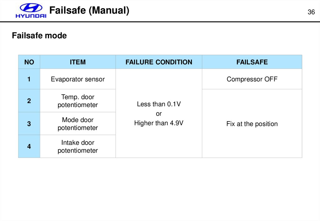
Failsafe (Manual)36
Failsafe mode
NO
ITEM
1
Evaporator sensor
2
Temp. door
potentiometer
3
Mode door
potentiometer
4
Intake door
potentiometer
FAILURE CONDITION
FAILSAFE
Compressor OFF
Less than 0.1V
or
Higher than 4.9V
Fix at the position
31.
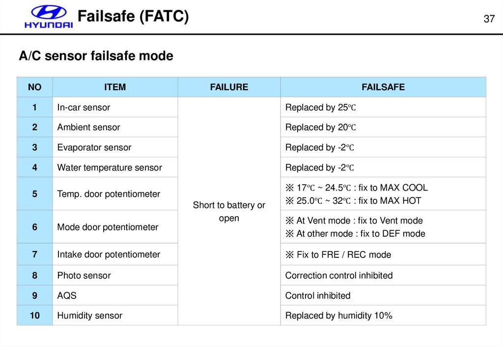
Failsafe (FATC)37
A/C sensor failsafe mode
NO
ITEM
FAILURE
FAILSAFE
1
In-car sensor
Replaced by 25℃
2
Ambient sensor
Replaced by 20℃
3
Evaporator sensor
Replaced by -2℃
4
Water temperature sensor
Replaced by -2℃
5
Temp. door potentiometer
※ 17℃ ~ 24.5℃ : fix to MAX COOL
※ 25.0℃ ~ 32℃ : fix to MAX HOT
Short to battery or
open
6
Mode door potentiometer
※ At Vent mode : fix to Vent mode
※ At other mode : fix to DEF mode
7
Intake door potentiometer
※ Fix to FRE / REC mode
8
Photo sensor
Correction control inhibited
9
AQS
Control inhibited
10
Humidity sensor
Replaced by humidity 10%
32.
Failsafe (FATC)38
DTC reading procedure
Ignition switch : OFF→ON
Press the MODE switch more than 4 times within 2
seconds during pressing the OFF switch.
After graphic symbol display blinks 3times, start
self-diagnosis
Keep pressing
Self-diagnosis (Continuous operation)
Press AUTO
Press AUTO
Self-diagnosis (Step operation by A/C SW)
Press OFF
Return to original condition
Press OFF
Press mode 4 times
33.
Failsafe (FATC)39
DTC list (Binary code displayed on the controller)
DTC
DESCRIPTION
00
NORMAL
11
INCAR SENSOR OPEN
12
INCAR SENSOR SHORT
13
AMBIENT SENSOR OPEN
14
AMBIENT SENSOR SHORT
15
WATER TEMP SENSOR OPEN
16
WATER TEMP SENSOR SHORT
17
EVAP SENSOR OPEN
18
EVAP SENSOR SHORT
19
TEMP DOOR POTENTIOMETER OPEN/SHORT(DRIVER SIDE)
20
DEFECTIVE TEMP DOOR POTENTIOMETER
21
MODE DOOR POTENTIOMETER OPEN/SHORT(DRIVER SIDE)
22
DEFECTIVE MODE DOOR POTENTIOMETER
23
HUMIDITY SENSOR OPEN
24
HUMIDITY SENSOR SHORT
34.
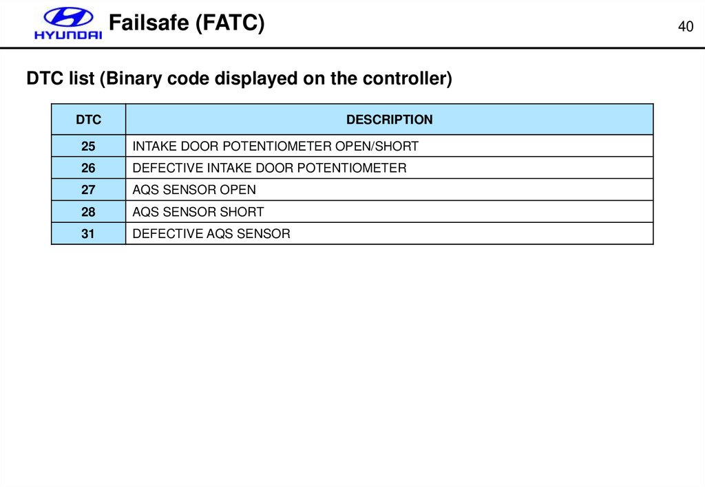
Failsafe (FATC)40
DTC list (Binary code displayed on the controller)
DTC
DESCRIPTION
25
INTAKE DOOR POTENTIOMETER OPEN/SHORT
26
DEFECTIVE INTAKE DOOR POTENTIOMETER
27
AQS SENSOR OPEN
28
AQS SENSOR SHORT
31
DEFECTIVE AQS SENSOR
35.
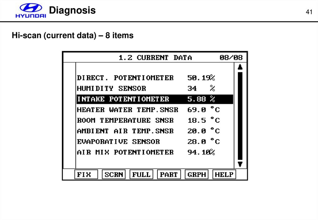
DiagnosisHi-scan (current data) – 8 items
41
36.
DiagnosisHi-scan (Actuator test)
42
37.
DiagnosisHi-scan (Actuator test)
43
38.
DiagnosisHi-scan (Actuator test)
44
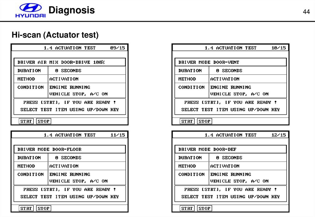
39.
DiagnosisHi-scan (Actuator test)
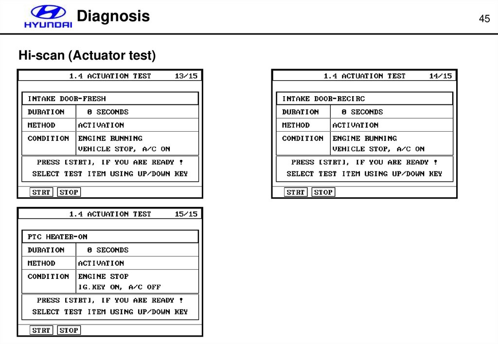
45
40.
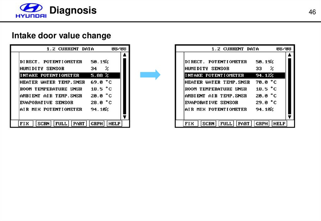
DiagnosisIntake door value change
46
41.
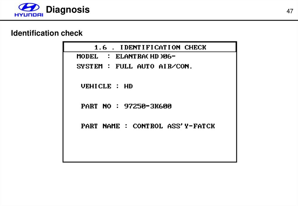
DiagnosisIdentification check
47