


 Электроника
Похожие презентации:


")
PAP 3400 service manual
1.
PAP 3400service manual
2.
content1、 Product introduce..………..p3-p4
2、 Disassembly guide ……….p5-p17
3、Structure parts diagram…..p18
4、 Repairing guide …………...p19-p29
2
3.
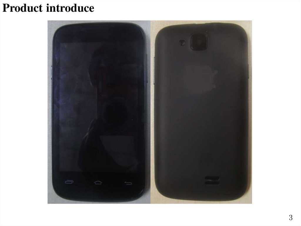
Product introduce3
4.
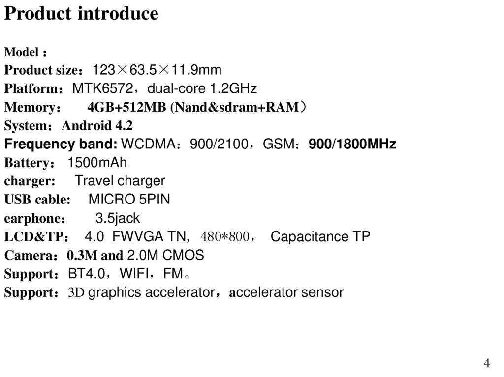
Product introduceModel
Product size 123×63.5×11.9mm
Platform MTK6572 dual-core 1.2GHz
Memory 4GB+512MB (Nand&sdram+RAM
System Android 4.2
Frequency band: WCDMA 900/2100 GSM 900/1800MHz
Battery 1500mAh
charger: Travel charger
USB cable: MICRO 5PIN
earphone 3.5jack
LCD&TP 4.0 FWVGA TN, 480*800 Capacitance TP
Camera 0.3M and 2.0M CMOS
Support BT4.0 WIFI FM。
Support 3D graphics accelerator accelerator sensor
4
5.
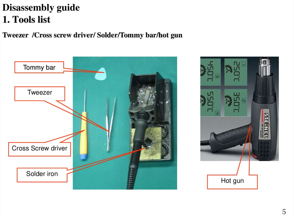
Disassembly guide1. Tools list
Tweezer /Cross screw driver/ Solder/Tommy bar/hot gun
Tommy bar
Tweezer
Cross Screw driver
Solder iron
Hot gun
5
6.
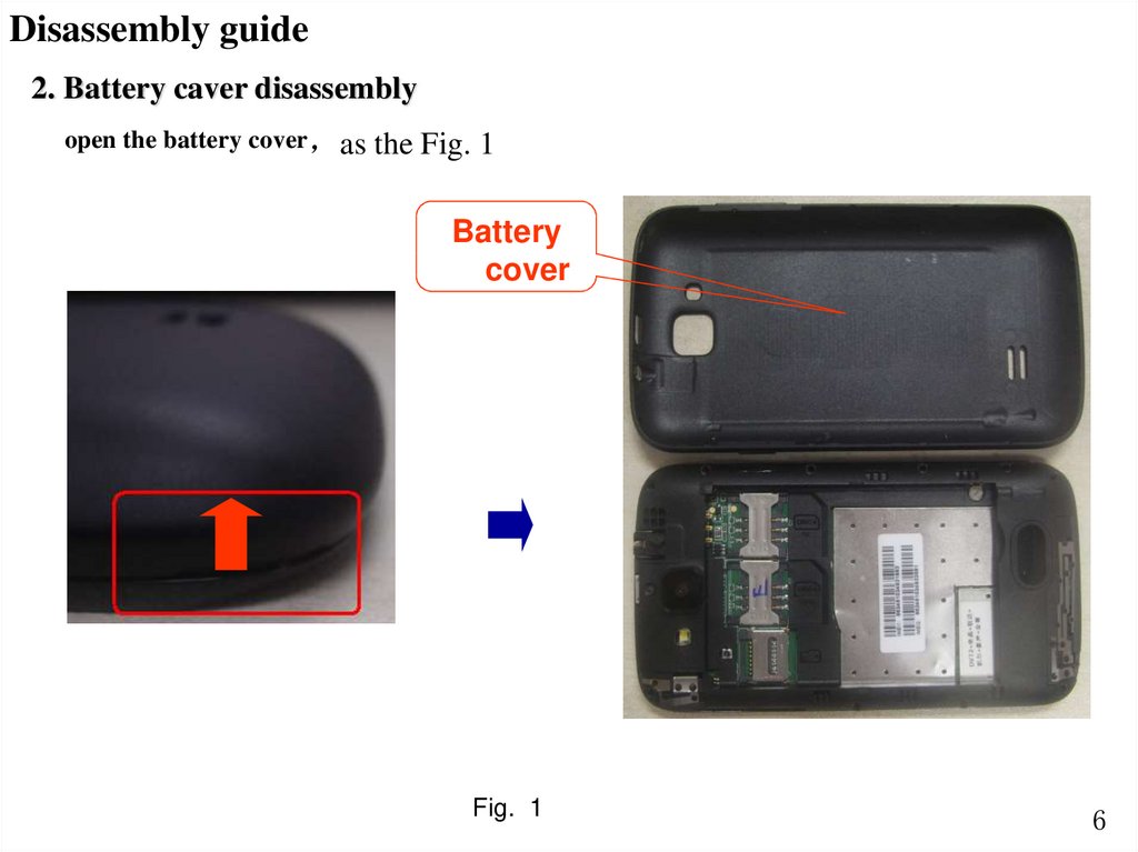
Disassembly guide2. Battery caver disassembly
open the battery cover as
the Fig. 1
Battery
cover
Fig. 1
6
7.
Disassembly guide3. Back caver disassembly
1 Unscrew 10 screws in back cover as the Fig.2
Fig. 2
7
8.
Disassembly guide2 Disassemble back cover with Tommy bar as the Fig.3
Back
cover
Fig. 3
SPK
8
9.
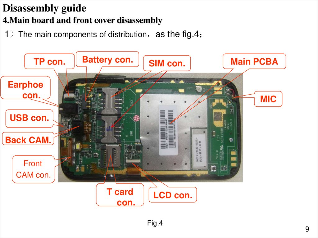
Disassembly guide4.Main board and front cover disassembly
1 The main components of distribution as the fig.4
TP con.
Battery con.
SIM con.
Earphoe
con.
Main PCBA
MIC
USB con.
Back CAM.
Front
CAM con.
T card
con.
LCD con.
Fig.4
9
10.
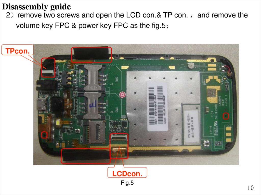
Disassembly guide2 remove two screws and open the LCD con.& TP con. and remove the
volume key FPC & power key FPC as the fig.5
TPcon.
LCDcon.
Fig.5
10
11.
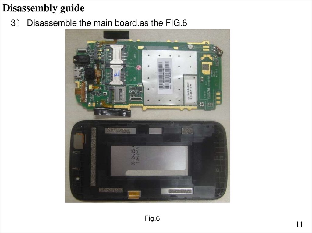
Disassembly guide3 Disassemble the main board.as the FIG.6
Fig.6
11
12.
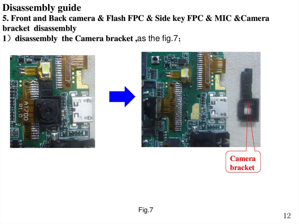
Disassembly guide5. Front and Back camera & Flash FPC & Side key FPC & MIC &Camera
bracket disassembly
1 disassembly the Camera bracket ,as the fig.7
Camera
bracket
Fig.7
12
13.
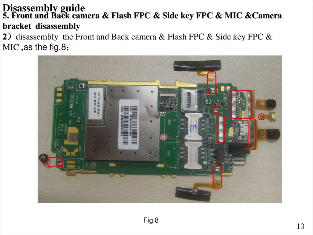
Disassembly guide5. Front and Back camera & Flash FPC & Side key FPC & MIC &Camera
bracket disassembly
2 disassembly the Front and Back camera & Flash FPC & Side key FPC &
MIC ,as the fig.8
Fig.8
13
14.
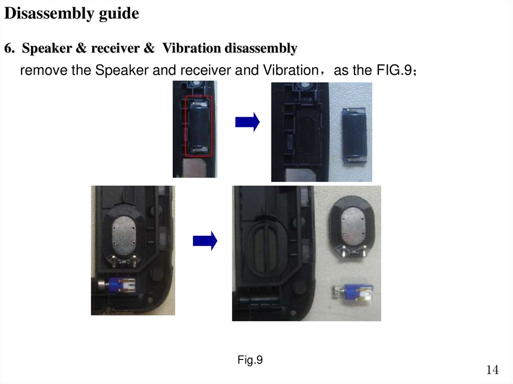
Disassembly guide6. Speaker & receiver & Vibration disassembly
remove the Speaker and receiver and Vibration as the FIG.9
Fig.9
14
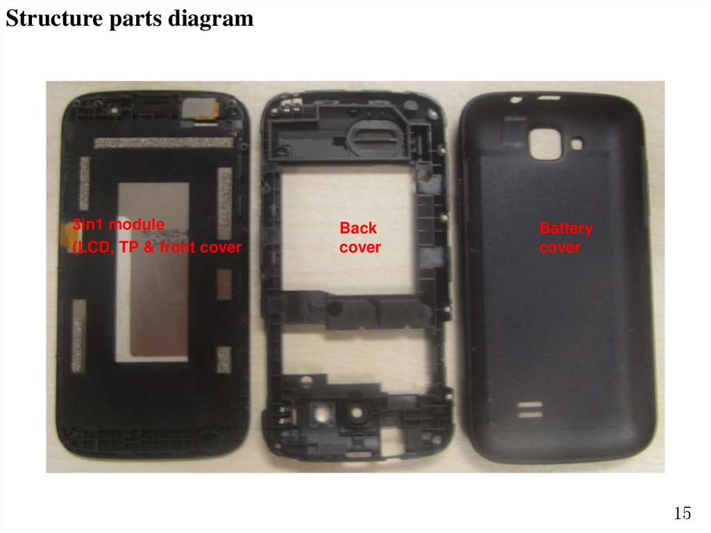
15.
Structure parts diagram3in1 module
(LCD, TP & front cover
Back
cover
Battery
cover
15
16.
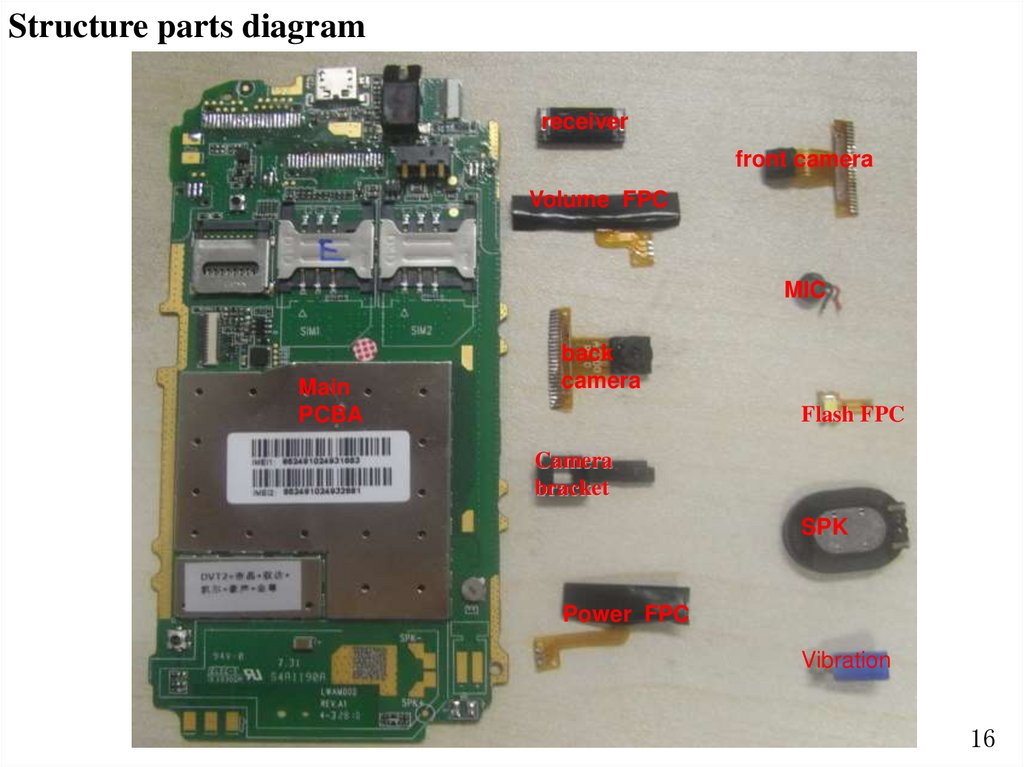
Structure parts diagramreceiver
front camera
Volume FPC
MIC
Main
PCBA
back
camera
Flash FPC
Camera
bracket
SPK
Power FPC
Vibration
16
17.
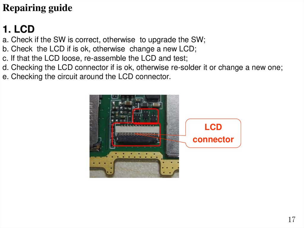
Repairing guide1. LCD
a. Check if the SW is correct, otherwise to upgrade the SW;
b. Check the LCD if is ok, otherwise change a new LCD;
c. If that the LCD loose, re-assemble the LCD and test;
d. Checking the LCD connector if is ok, otherwise re-solder it or change a new one;
e. Checking the circuit around the LCD connector.
LCD
connector
17
18.
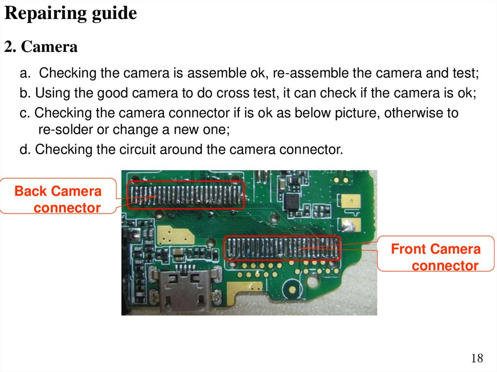
Repairing guide2. Camera
a. Checking the camera is assemble ok, re-assemble the camera and test;
b. Using the good camera to do cross test, it can check if the camera is ok;
c. Checking the camera connector if is ok as below picture, otherwise to
re-solder or change a new one;
d. Checking the circuit around the camera connector.
Back Camera
connector
Front Camera
connector
18
19.
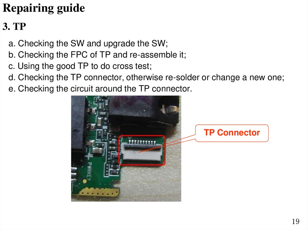
Repairing guide3. TP
a. Checking the SW and upgrade the SW;
b. Checking the FPC of TP and re-assemble it;
c. Using the good TP to do cross test;
d. Checking the TP connector, otherwise re-solder or change a new one;
e. Checking the circuit around the TP connector.
TP Connector
19
20.
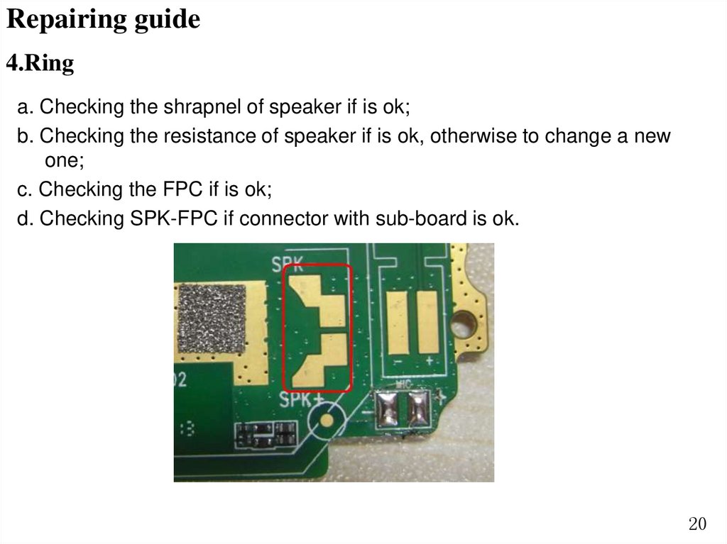
Repairing guide4.Ring
a. Checking the shrapnel of speaker if is ok;
b. Checking the resistance of speaker if is ok, otherwise to change a new
one;
c. Checking the FPC if is ok;
d. Checking SPK-FPC if connector with sub-board is ok.
20
21.
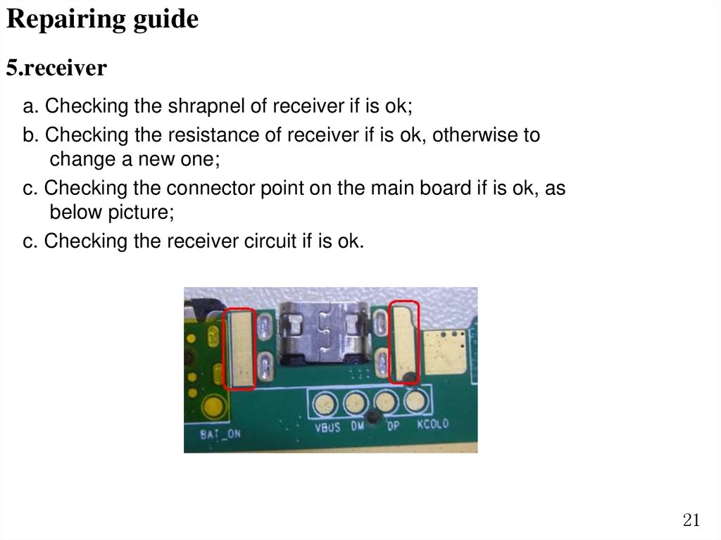
Repairing guide5.receiver
a. Checking the shrapnel of receiver if is ok;
b. Checking the resistance of receiver if is ok, otherwise to
change a new one;
c. Checking the connector point on the main board if is ok, as
below picture;
c. Checking the receiver circuit if is ok.
21
22.
Repairing guide6.MIC and Vibrator
a. Checking the MIC and Vibrator is cold soldering, re-solder it;
b. Change the MIC and Vibrator;
c. Checking the circuit of MIC and Vibrator;
d. Checking the FPC if connect ok.
MIC con.
22
23.
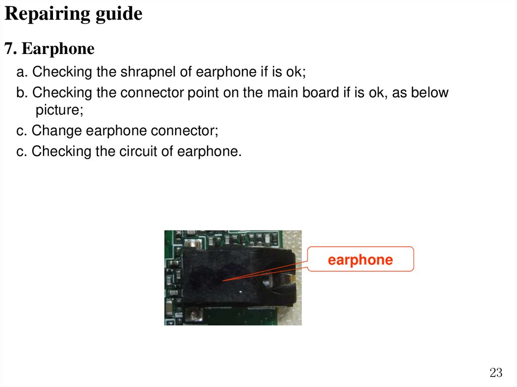
Repairing guide7. Earphone
a. Checking the shrapnel of earphone if is ok;
b. Checking the connector point on the main board if is ok, as below
picture;
c. Change earphone connector;
c. Checking the circuit of earphone.
earphone
23
24.
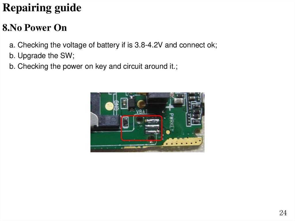
Repairing guide8.No Power On
a. Checking the voltage of battery if is 3.8-4.2V and connect ok;
b. Upgrade the SW;
b. Checking the power on key and circuit around it.;
24
25.
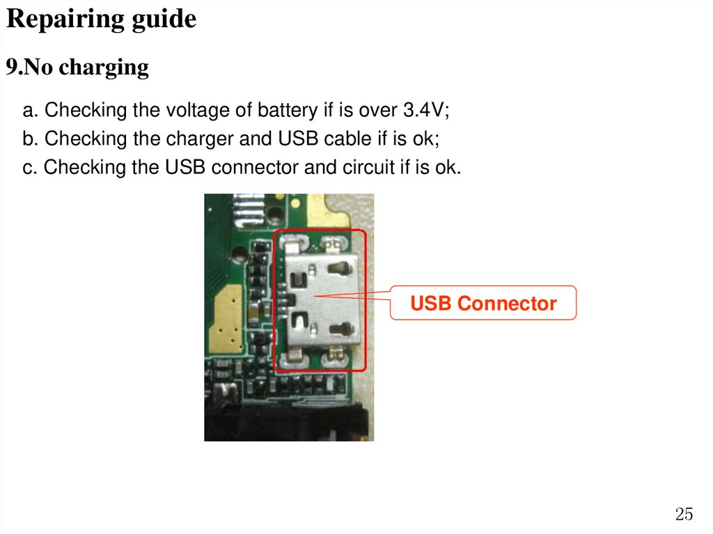
Repairing guide9.No charging
a. Checking the voltage of battery if is over 3.4V;
b. Checking the charger and USB cable if is ok;
c. Checking the USB connector and circuit if is ok.
USB Connector
25
26.
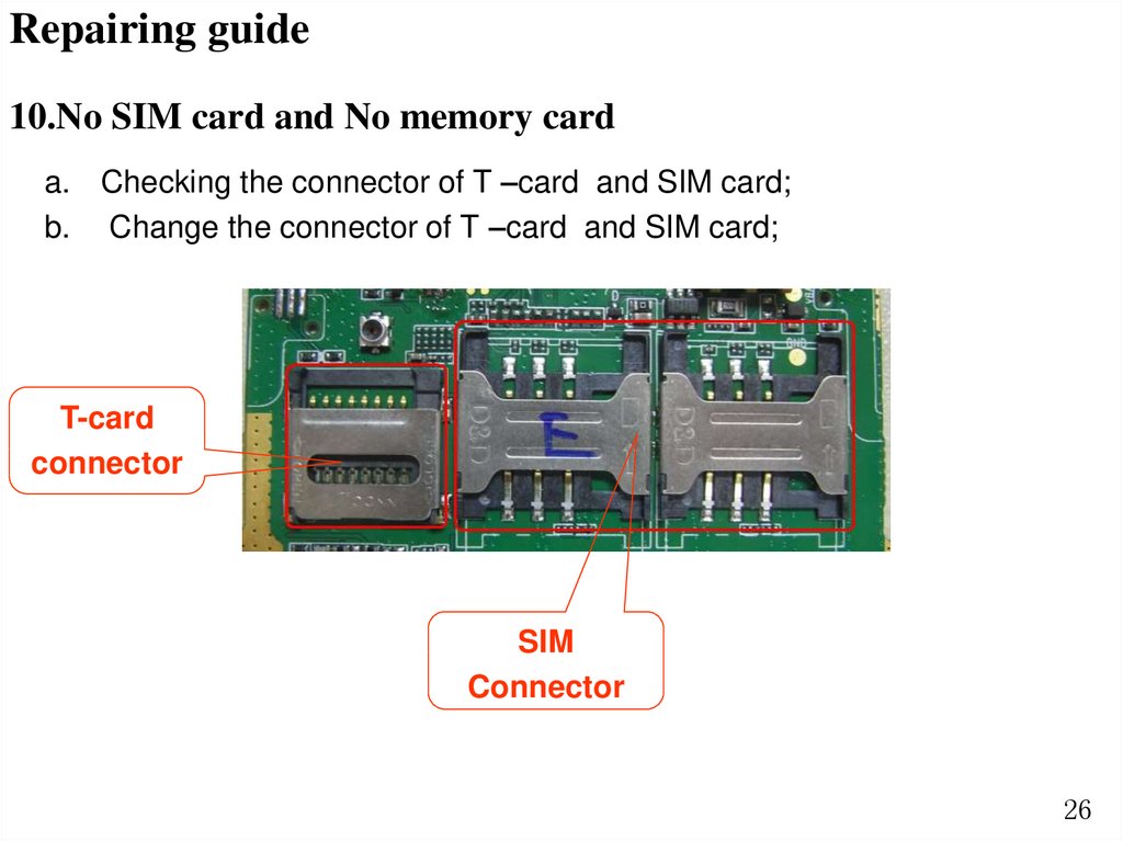
Repairing guide10.No SIM card and No memory card
a. Checking the connector of T –card and SIM card;
b. Change the connector of T –card and SIM card;
T-card
connector
SIM
Connector
26
27.
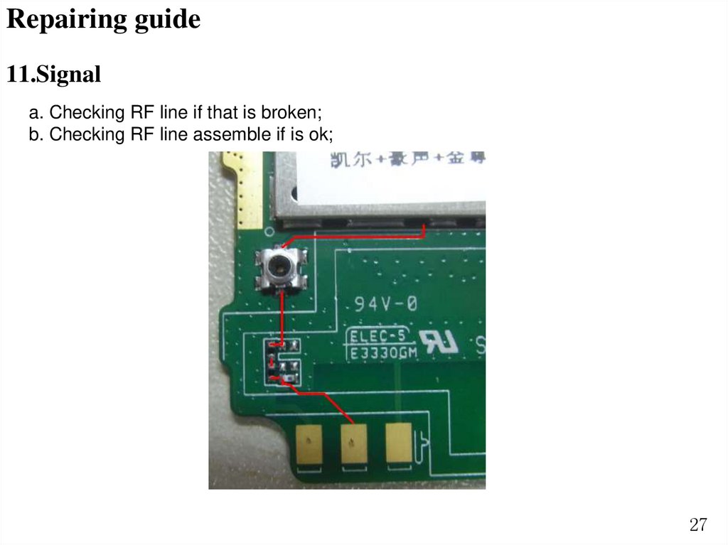
Repairing guide11.Signal
a. Checking RF line if that is broken;
b. Checking RF line assemble if is ok;
27
28.
EndQ&A