 Благітко Б.Я. 2019 р.")


")
")
")
")
")
")


 Благітко Б.Я. 2019 р.")
 Экономика
Похожие презентации:


")

")
Мікропроцесорна техніка (лекція 6)
1. Мікропроцесорна техніка (лекція 6) Благітко Б.Я. 2019 р.
PSoC Creator 4.2Designing with PSoC 3/5
2. Мікропроцесорна техніка ADC+LCD
Мікропроцесорна
техніка
ADC+LCD
PSoC Creator 4.2
Designing with PSoC 3/5
3. Зміст
PSoC 3/5 включає в себеможливість обробки аналогових,
цифрових і змішаних сигналів, а
також
можливість
формування
аналогових і цифрових сигналів,
охоплюючи
широкий
спектр
прикладних задач
3
4.
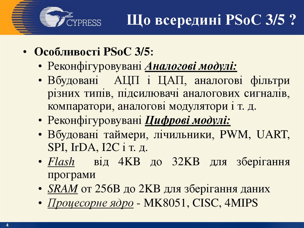
Що всередині PSoC 3/5 ?• Особливості PSoC 3/5:
• Реконфігуровувані Аналогові модулі:
• Вбудовані АЦП і ЦАП, аналогові фільтри
різних типів, підсилювачі аналогових сигналів,
компаратори, аналогові модулятори і т. д.
• Реконфігуровувані Цифрові модулі:
• Вбудовані таймери, лічильники, PWM, UART,
SPI, IrDA, I2C і т. д.
• Flash
від 4KB до 32KB для зберігання
програми
• SRAM от 256B до 2KB для зберігання даних
• Процесорне ядро - MK8051, CISC, 4MIPS
4
5. Оптимальні області застосування МК PSoC
Оптимальними для PSoC являютьсязадачі, коли необхідна обробка
аналогових сигналів на апаратному рівні
(підсилення, фільтрація, AM/FM
модуляція, демодуляція) із наступним
перетворенням в цифрову форму в
смузі аналогових сигналів до 100 кГц.
Виграш полягає в переносі зовнішніх
дискретних компонентів у середину
процесора.
5
6. Цифрові та аналогові модулі
67. Цифрові та аналогові модулі
78. ADC
Принцип дії даного АЦП дещо більш складний, ніж уінших типів АЦП.
Його суть в тому, що вхідна напруга порівнюється зі
значенням напруги, накопиченим інтегратором.
На вхід інтегратора подаються імпульси позитивної
чи від'ємної полярності, в залежності від результату
порівняння.
Таким чином, даний АЦП представляє собою просту
слідкуючу
систему:
напруга
на
виході
інтегратора
«відслідковує» вхідну напругу (рис. ).
Результатом роботи даної схеми являється потік
нулів та одиниць на виході компаратора, який потім
пропускається
через
цифровий
ФНЧ,
в
результаті
получається N-бітний результат.
ФНЧ на рис.
об'єднаний з «дециматором»,
пристроєм, який понижує частоту слідування відліків
шляхом
їх
«проріджування».
8
9. Delta Sigma Analog to Digital Converter (ADC_DelSig)
ADC_DelSig Block Diagram9
10. Delta Sigma Analog to Digital Converter (ADC_DelSig)
Структурна схема сигма-дельта АЦПСтруктурна схема сигма-дельта АЦП.
10
11. Delta Sigma Analog to Digital Converter (ADC_DelSig)
Сигма-дельта АЦП як слідкуюча система11
12. Delta Sigma Analog to Digital Converter (ADC_DelSig)
1.When processing audio information, theADC_DelSig is used in a continuous operation
mode.
2.When used for scanning multiple sensors, the
ADC_DelSig is used in one of the multisample
modes.
3.When used for single-point high-resolution
measurements, the ADC_DelSig is used in
single-sample mode.
4.Delta-sigma converters are good for both highspeed medium-resolution (8 to 16 bits)
applications, and low-speed high-resolution (16
to 20 bits) applications. The sample rate can be
adjusted between 10 and 384000 samples per
second, depending on mode and resolution.
12
13. Delta Sigma Analog to Digital Converter (ADC_DelSig)
It can produce 16-bit.13
14. Delta Sigma Analog to Digital Converter (ADC_DelSig)
1. When used for single-point high-resolutionmeasurements, the ADC_DelSig is used in singlesample mode.
2. Delta-sigma converters are good for both highspeed medium-resolution (8 to 16 bits)
applications.
3. The sample rate can be adjusted between 2000
and
38400 samples per second, depending on
mode and resolution.
14
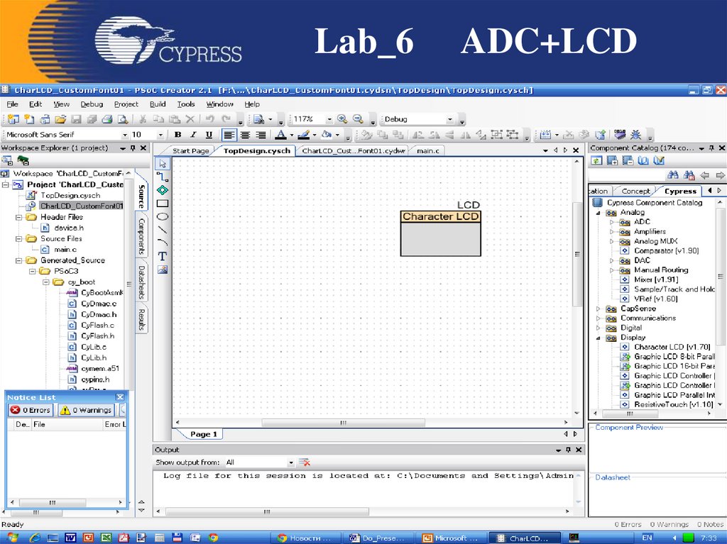
15. ADC+LCD
This example project shows how youcan use PSoC to transfer data from one
peripheral (ADC) to another (LDC),
15
16. ADC+LCD
Features• Delta-Sigma ADC in single-ended mode
• LCD used to verify output
16
17. Creator
1718. File – New - Projekt
1819. Empty PSoC 3/5 Design
1920.
Lab_620
ADC+LCD
21.
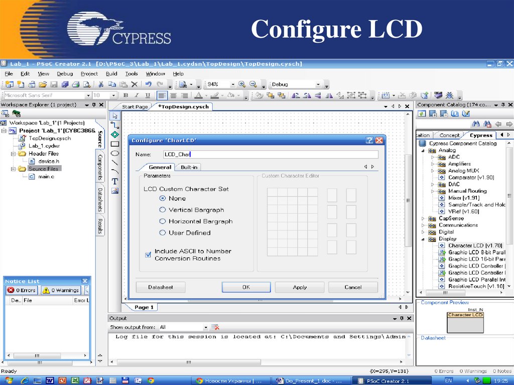
Configure LCD21
22.
Lab_622
ADC+LCD
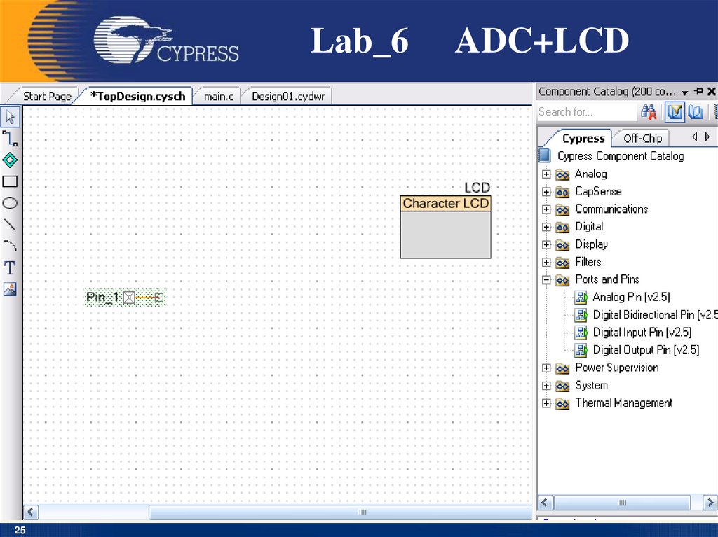
23. ADC+LCD
Adding ComponentsTo see how the ADC works we need an analog
signal to convert. We’re going to use a
potentiometer to provide one analog signal. A basic
potentiometer provides a great diagnostic tool for
analog processing since you can slowly sweep the
signal through the range of the potentiometer and
observe the output. Char LCD to provide visual
feedback.
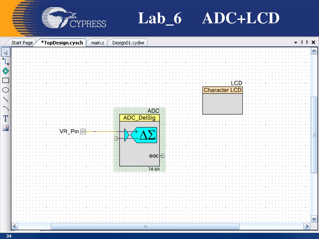
1. Drag an Analog Pin component onto your design.
2. Name it VR_Pin. This pin will be connected to the
potentiometer on the DVK.
3. The potentiometer output will
send to the ADC.
23
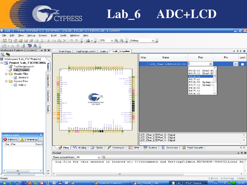
24.
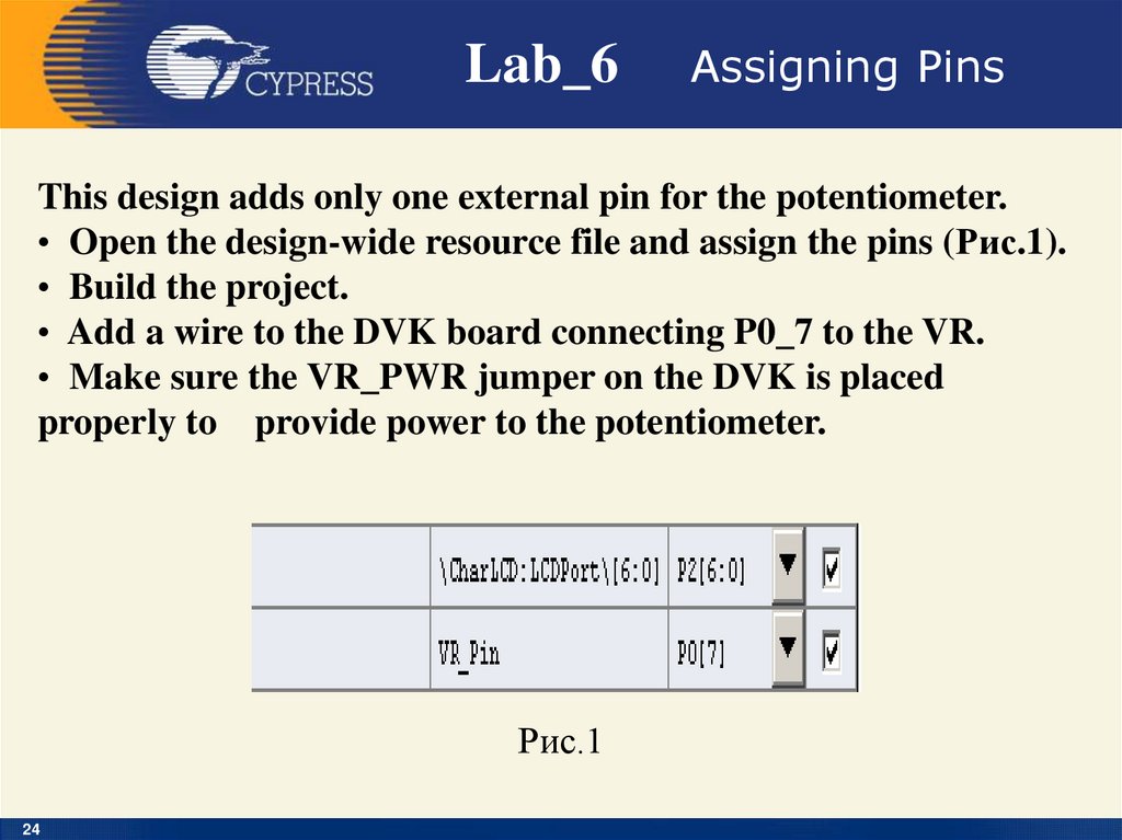
Lab_6Assigning Pins
This design adds only one external pin for the potentiometer.
• Open the design-wide resource file and assign the pins (Рис.1).
• Build the project.
• Add a wire to the DVK board connecting P0_7 to the VR.
• Make sure the VR_PWR jumper on the DVK is placed
properly to provide power to the potentiometer.
Рис.1
24
25.
Lab_625
ADC+LCD
26.
Lab_626
ADC+LCD
27.
Lab_627
ADC+LCD
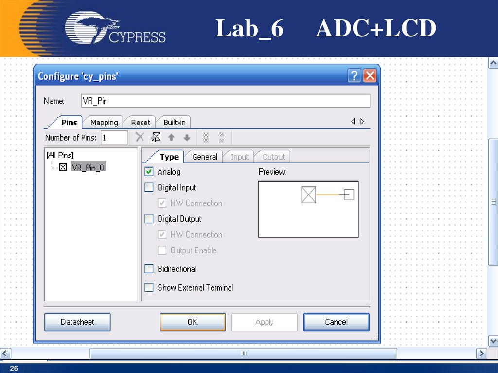
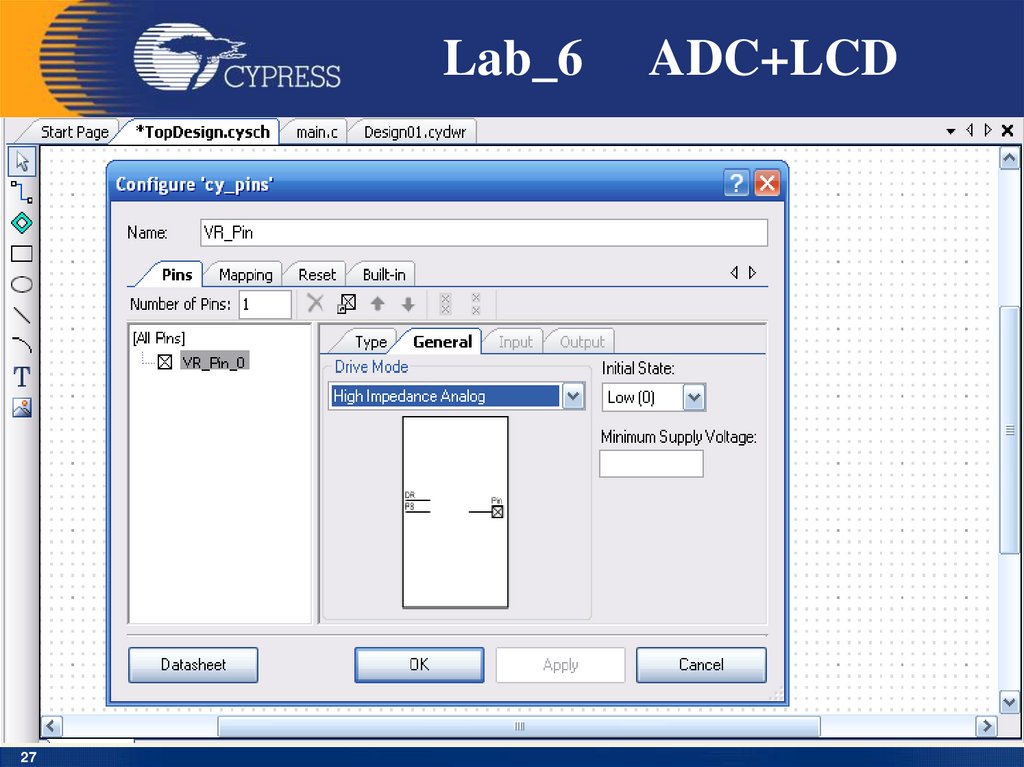
28.
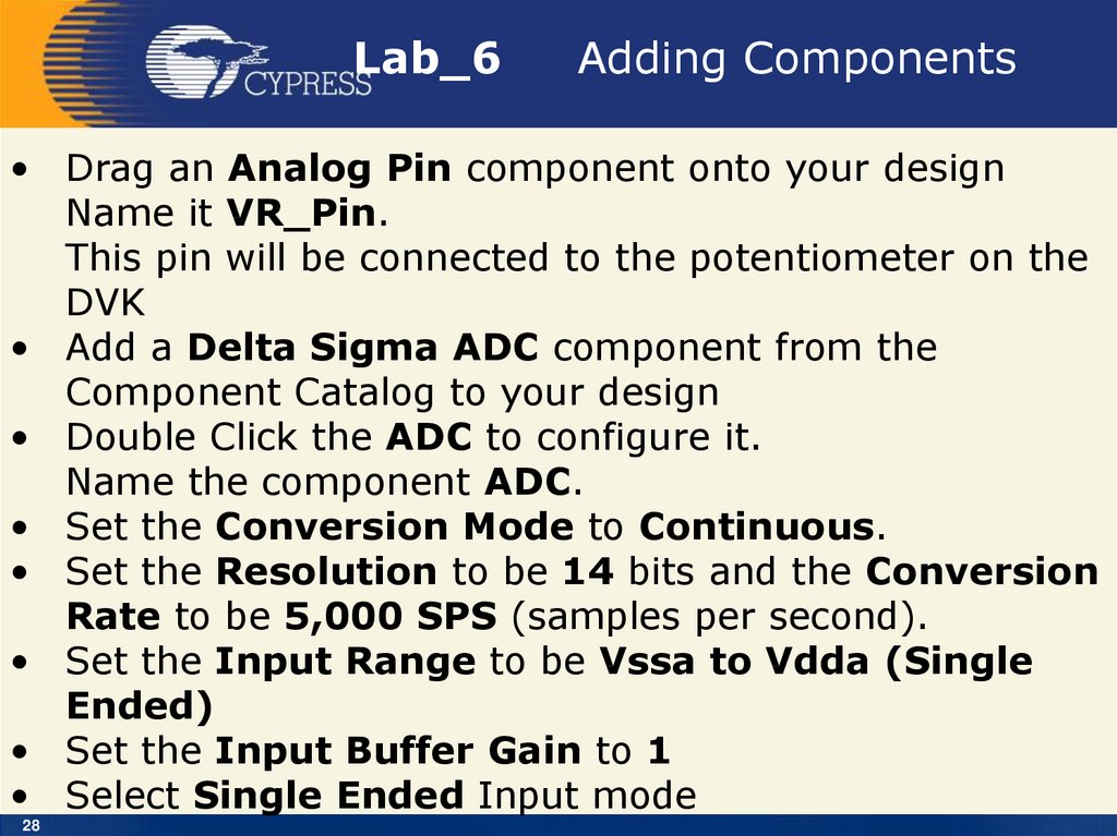
Lab_6Adding Components
• Drag an Analog Pin component onto your design
Name it VR_Pin.
This pin will be connected to the potentiometer on the
DVK
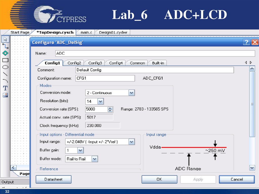
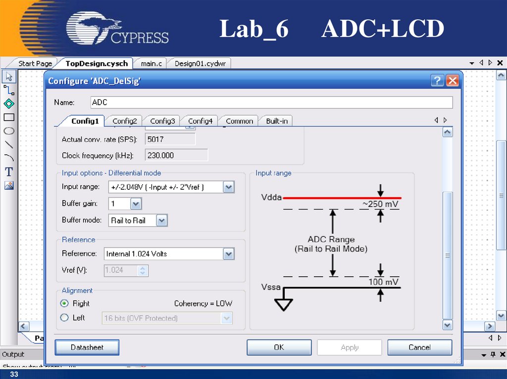
• Add a Delta Sigma ADC component from the
Component Catalog to your design
• Double Click the ADC to configure it.
Name the component ADC.
• Set the Conversion Mode to Continuous.
• Set the Resolution to be 14 bits and the Conversion
Rate to be 5,000 SPS (samples per second).
• Set the Input Range to be Vssa to Vdda (Single
Ended)
• Set the Input Buffer Gain to 1
• Select Single Ended Input mode
28
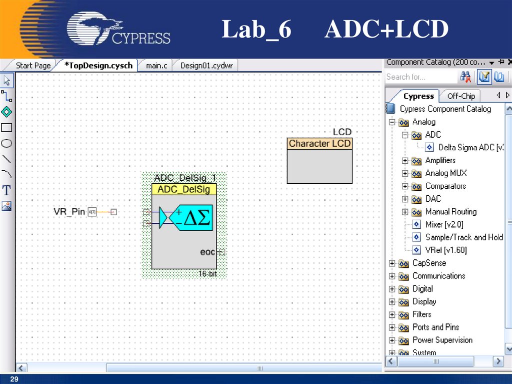
29.
Lab_629
ADC+LCD
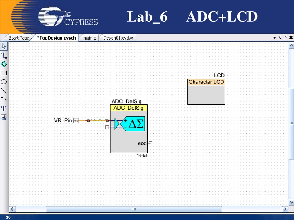
30.
Lab_630
ADC+LCD
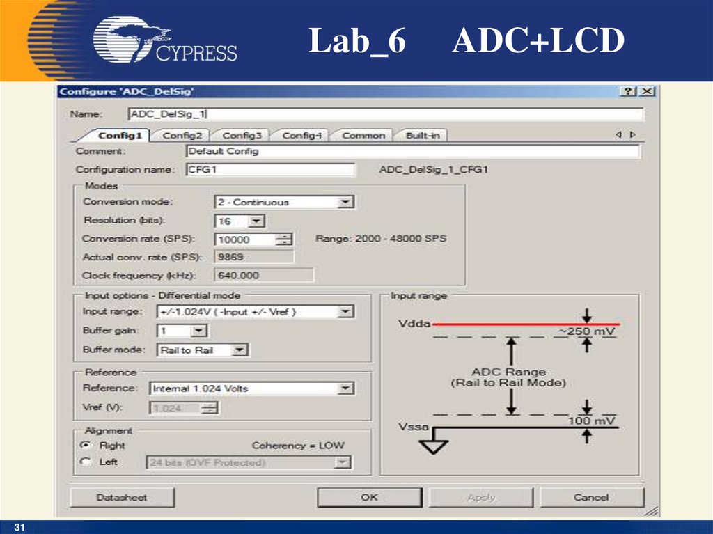
31.
Lab_631
ADC+LCD
32.
Lab_632
ADC+LCD
33.
Lab_633
ADC+LCD
34.
Lab_634
ADC+LCD
35.
Main.c35
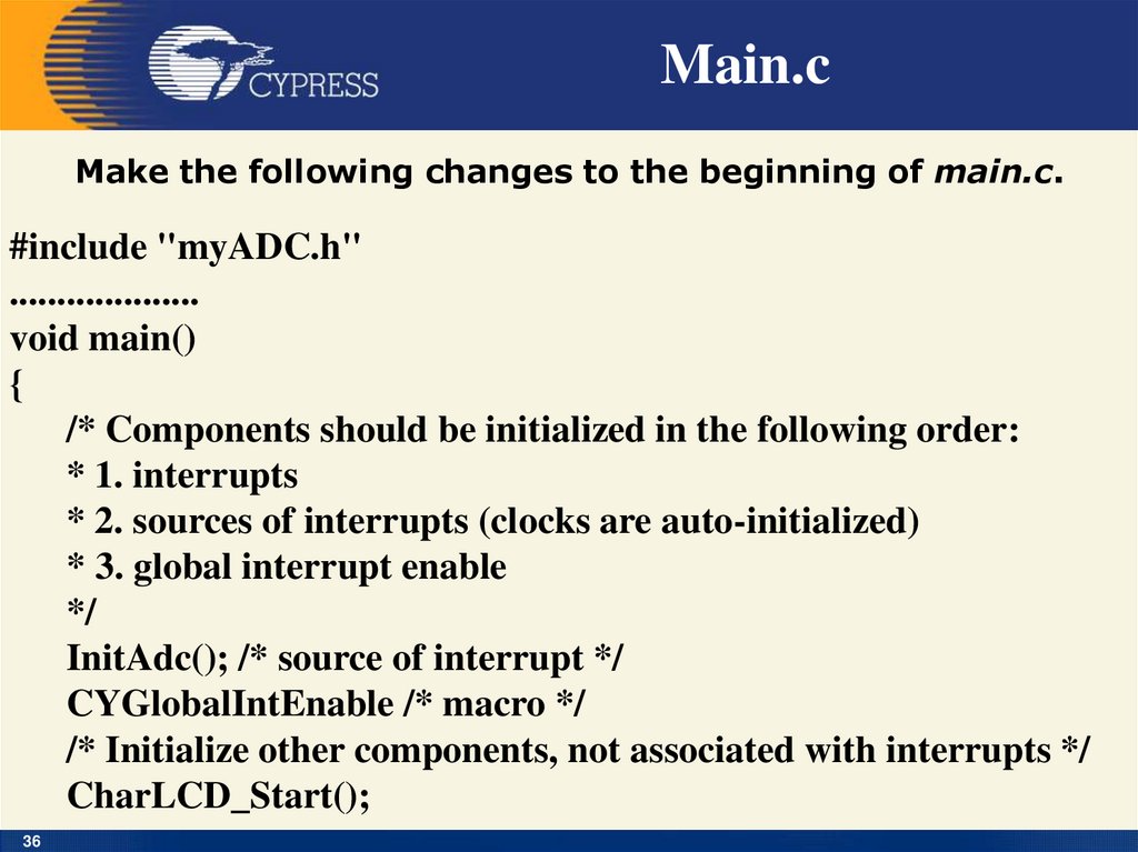
36.
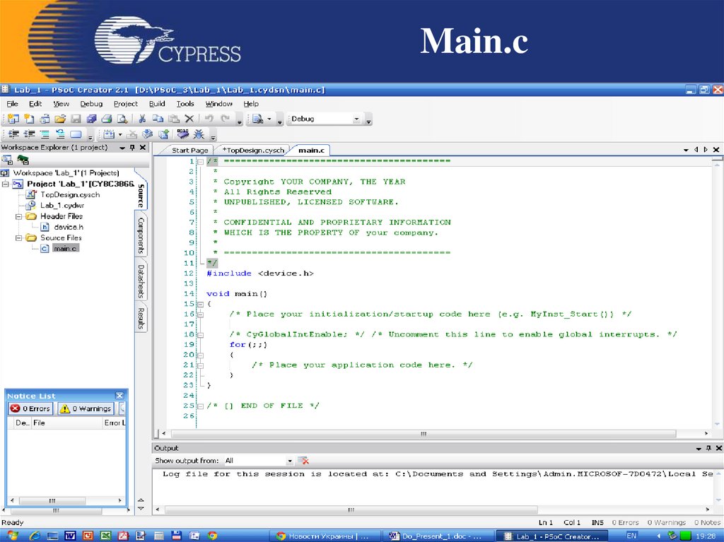
Main.cMake the following changes to the beginning of main.c.
#include "myADC.h"
....................
void main()
{
/* Components should be initialized in the following order:
* 1. interrupts
* 2. sources of interrupts (clocks are auto-initialized)
* 3. global interrupt enable
*/
InitAdc(); /* source of interrupt */
CYGlobalIntEnable /* macro */
/* Initialize other components, not associated with interrupts */
CharLCD_Start();
36
37.
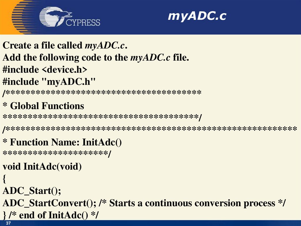
myADC.cCreate a file called myADC.c.
Add the following code to the myADC.c file.
#include <device.h>
#include "myADC.h"
/***************************************
* Global Functions
***************************************/
/**********************************************************
* Function Name: InitAdc()
*********************/
void InitAdc(void)
{
ADC_Start();
ADC_StartConvert(); /* Starts a continuous conversion process */
} /* end of InitAdc() */
37
38.
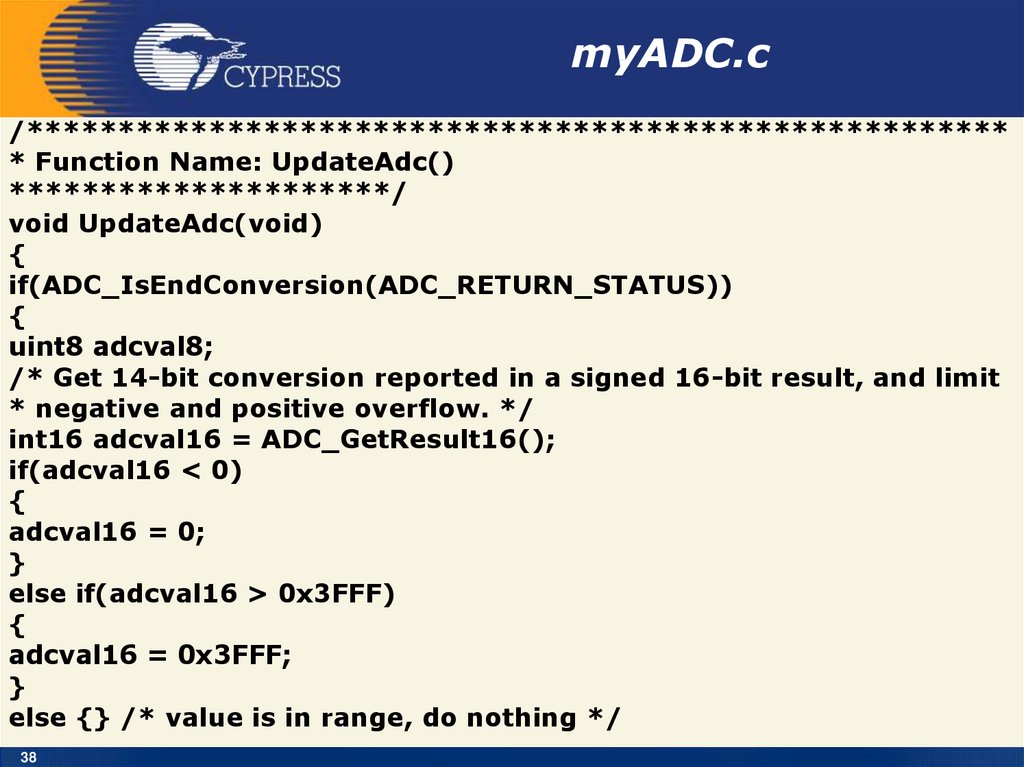
myADC.c/******************************************************
* Function Name: UpdateAdc()
*********************/
void UpdateAdc(void)
{
if(ADC_IsEndConversion(ADC_RETURN_STATUS))
{
uint8 adcval8;
/* Get 14-bit conversion reported in a signed 16-bit result, and limit
* negative and positive overflow. */
int16 adcval16 = ADC_GetResult16();
if(adcval16 < 0)
{
adcval16 = 0;
}
else if(adcval16 > 0x3FFF)
{
adcval16 = 0x3FFF;
}
else {} /* value is in range, do nothing */
38
39.
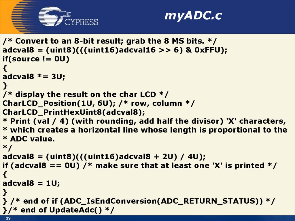
myADC.c/* Convert to an 8-bit result; grab the 8 MS bits. */
adcval8 = (uint8)(((uint16)adcval16 >> 6) & 0xFFU);
if(source != 0U)
{
adcval8 *= 3U;
}
/* display the result on the char LCD */
CharLCD_Position(1U, 6U); /* row, column */
CharLCD_PrintHexUint8(adcval8);
* Print (val / 4) (with rounding, add half the divisor) 'X' characters,
* which creates a horizontal line whose length is proportional to the
* ADC value.
*/
adcval8 = (uint8)(((uint16)adcval8 + 2U) / 4U);
if (adcval8 == 0U) /* make sure that at least one 'X' is printed */
{
adcval8 = 1U;
}
} /* end of if (ADC_IsEndConversion(ADC_RETURN_STATUS)) */
}/* end of UpdateAdc() */
39
40. Приклади застосування МК PSOC
На сайті фірмиCypress знаходиться
більше 200
Application Notes і
Reference Designs,
які ілюструють
області
застосування
мікроконтролерів
PSoC.
40
41. Мікропроцесорна техніка (лекція 6, кінець) Благітко Б.Я. 2019 р.
Мікропроцесорна
техніка
(лекція 6, кінець)
Благітко Б.Я.
2019 р.