


 Реклама
Похожие презентации:
 Engine")


CM MU(μ) Engine
1.
CMMU(μ) Engine
2.
Front View2
VIS 1
P/S Pump
Driving Belt
(Serpentine Belt)
Auto-tensioner
Alternator
Oxygen Sensor
A/C Compressor
Oil filter
3.
Rear View3
PCV Hose
ETC
CVVT
PCSV
ECT sensor
WCC
4.
Top View4
CVVT
ETC
Delivery Pipe
MAP
Ignition
Coil
VIS
5.
Specification5
Contents
μ- 2.7
Contents
μ- 2.7
Capacity(cc)
2,656
Fuel pressure (kg/㎠)
3.8
Compression Ratio
10.4
Fuel tank (L)
75
Camshaft type
DOHC(4 Valve)
Ignition timing
BTDC 10˚ ± 5
Max. Power (Ps/rpm)
192/6,000
Thermostat open/max
82 ˚C / 95 ˚C
Max. Torque (Kg.m/rpm)
25.5/4,200
Engine Oil (L)
4.5
Idle speed (rpm)
650±100
Engine Coolant (L)
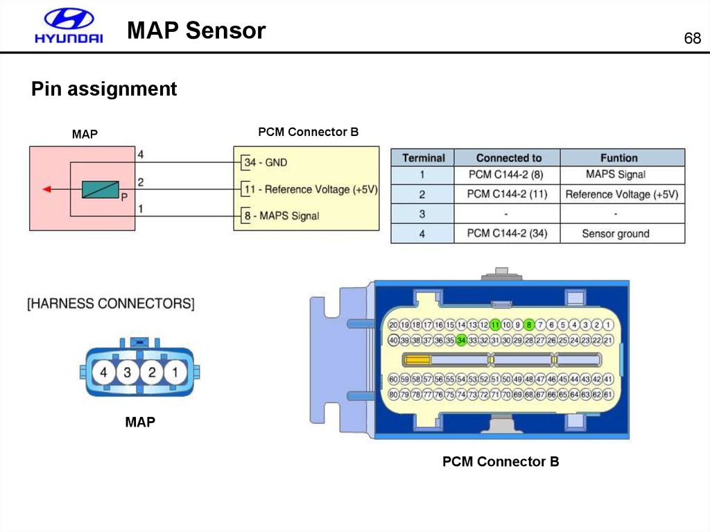
8.2
Bore(mm) × Stroke(mm)
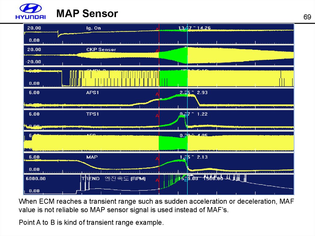
86.7 × 75
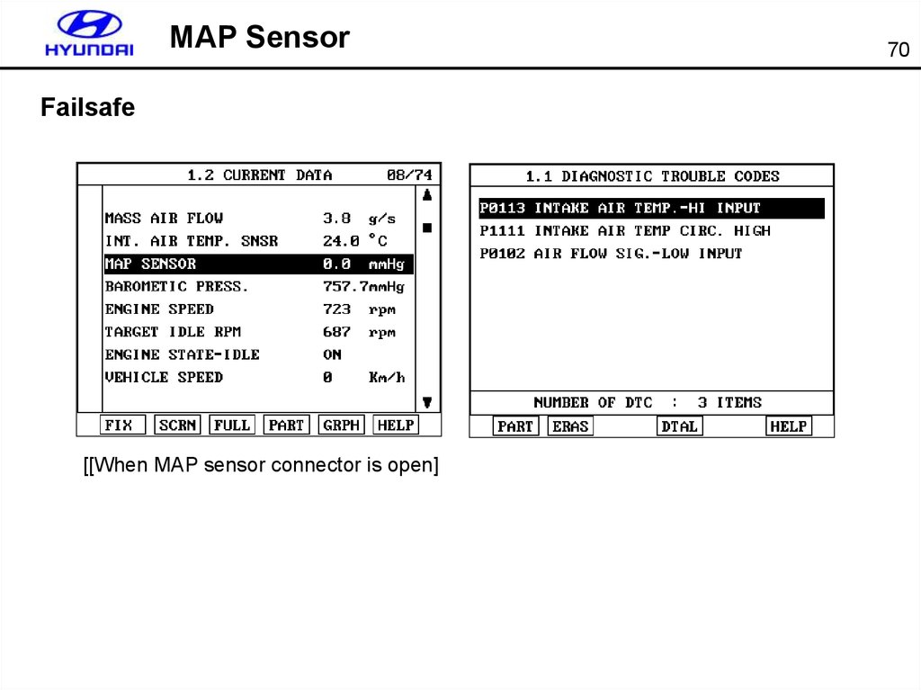
Ignition order
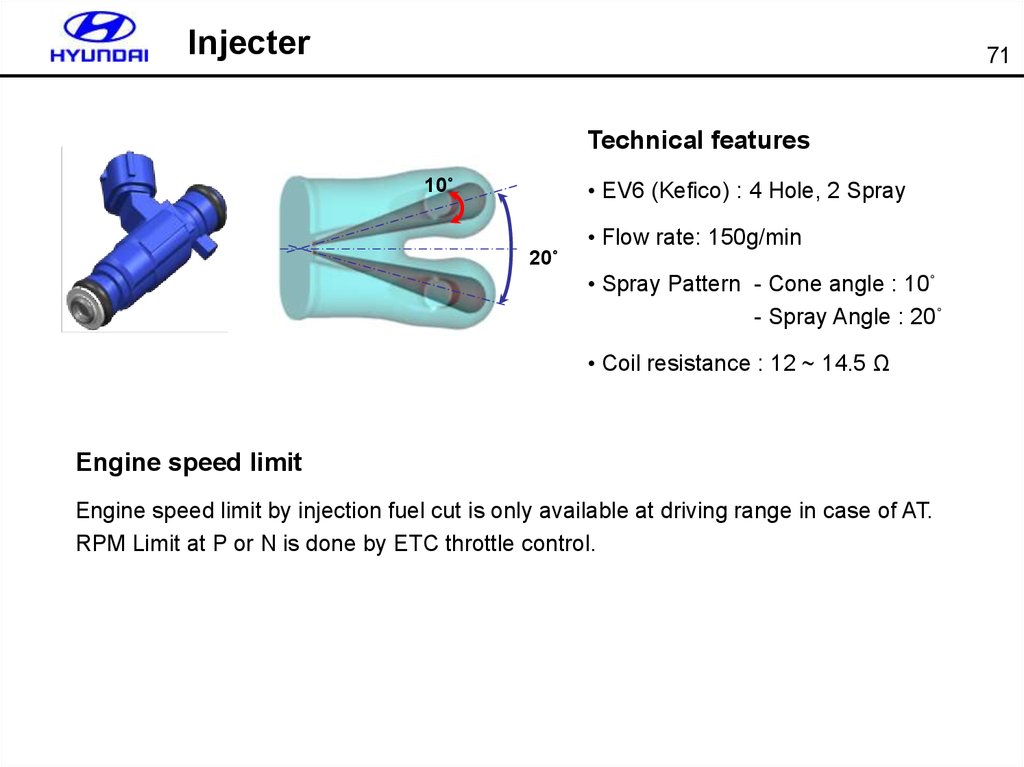
1-2-3-4-5-6
Valve system
MLA(Shim-less)
Cooling system
Inlet control
ETC
Standard
Oxygen Sensor
Zirconia
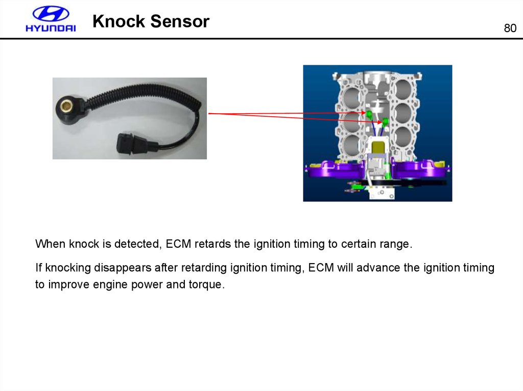
EMS
Delphi
6.
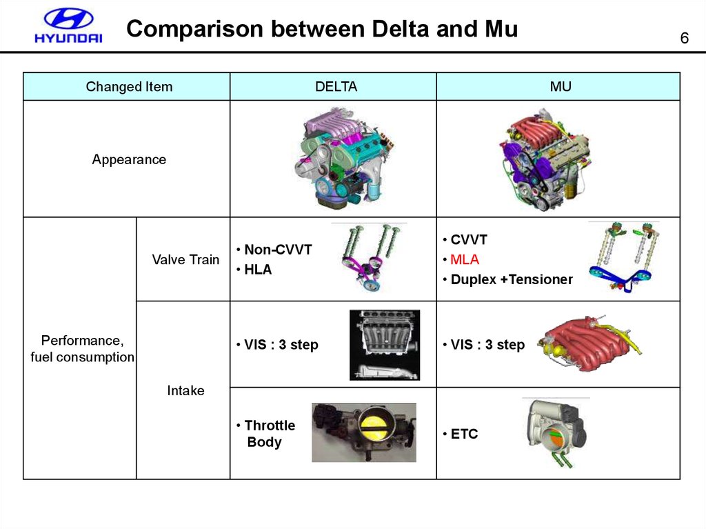
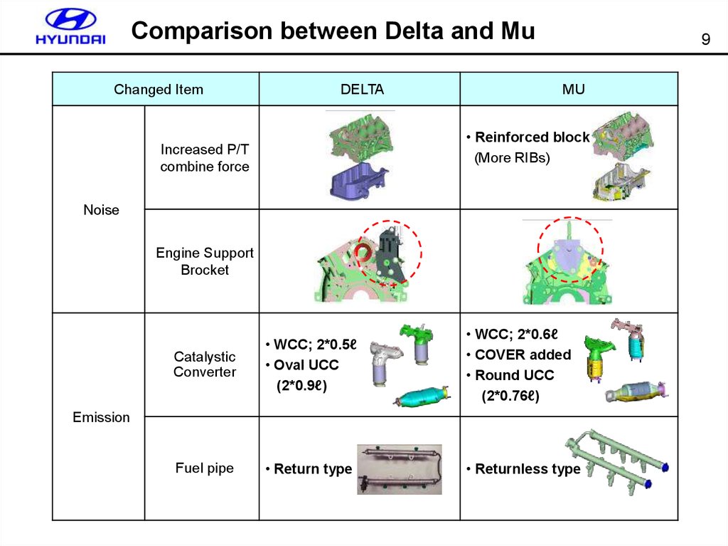
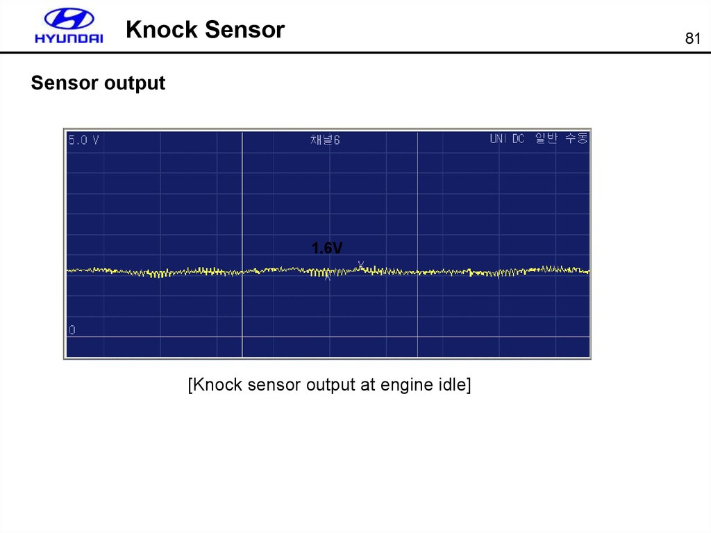
Comparison between Delta and MuChanged Item
DELTA
6
MU
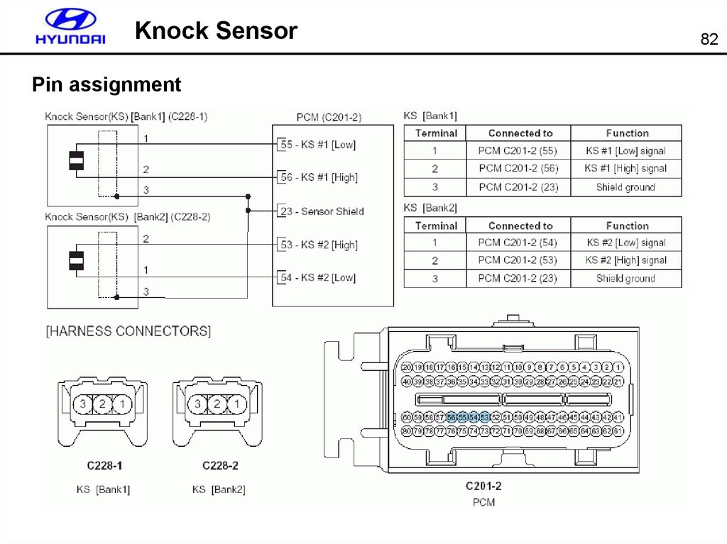
Appearance
Valve Train
Performance,
fuel consumption
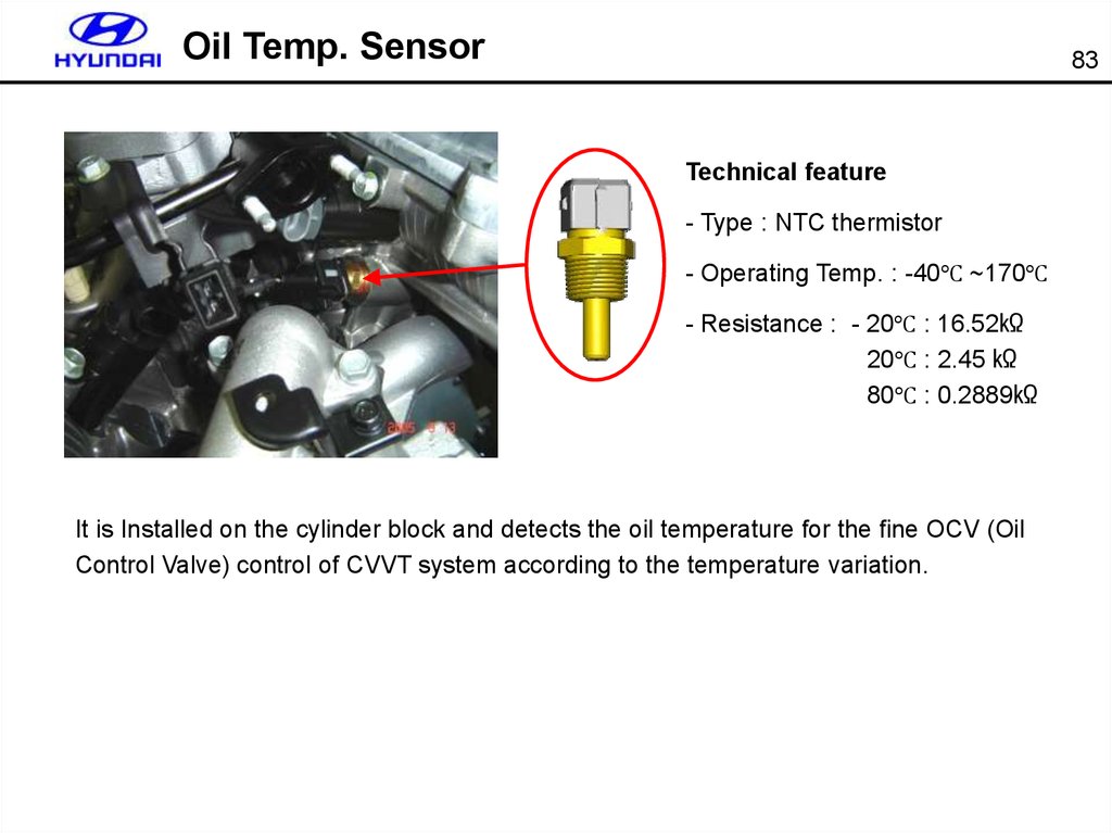
• Non-CVVT
• HLA
• CVVT
• MLA
• Duplex +Tensioner
• VIS : 3 step
• VIS : 3 step
• Throttle
Body
• ETC
Intake
7.
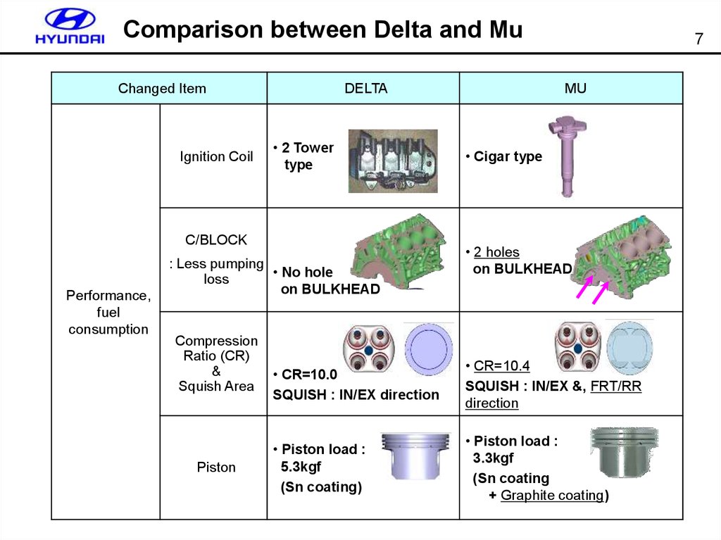
Comparison between Delta and MuChanged Item
Ignition Coil
DELTA
• 2 Tower
type
C/BLOCK
Performance,
fuel
consumption
: Less pumping
• No hole
loss
on BULKHEAD
Compression
Ratio (CR)
&
Squish Area
Piston
7
MU
• Cigar type
• 2 holes
on BULKHEAD
• CR=10.0
SQUISH : IN/EX direction
• CR=10.4
SQUISH : IN/EX &, FRT/RR
direction
• Piston load :
5.3kgf
(Sn coating)
• Piston load :
3.3kgf
(Sn coating
+ Graphite coating)
8.
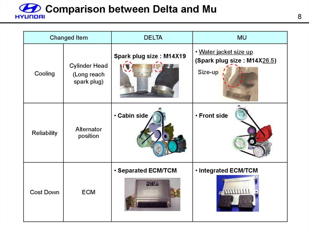
Comparison between Delta and MuChanged Item
DELTA
Spark plug size : M14X19
Cooling
Reliability
Cost Down
Cylinder Head
(Long reach
spark plug)
8
MU
• Water jacket size up
(Spark plug size : M14X26.5)
Size-up
• Cabin side
• Front side
• Separated ECM/TCM
• Integrated ECM/TCM
Alternator
position
ECM
9.
Comparison between Delta and MuChanged Item
DELTA
9
MU
• Reinforced block
(More RIBs)
Increased P/T
combine force
Noise
Engine Support
Brocket
Catalystic
Converter
• WCC; 2*0.5ℓ
• Oval UCC
(2*0.9ℓ)
• WCC; 2*0.6ℓ
• COVER added
• Round UCC
(2*0.76ℓ)
Fuel pipe
• Return type
• Returnless type
Emission
10.
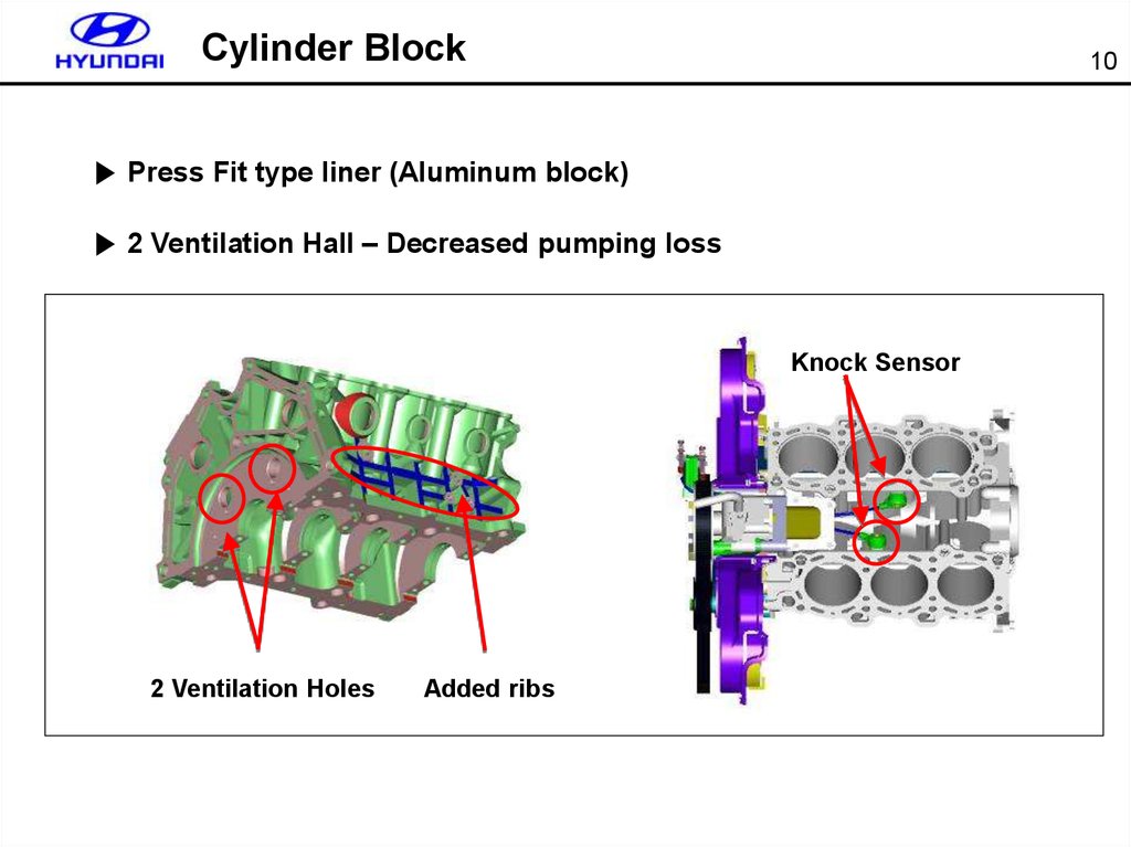
Cylinder Block10
▶ Press Fit type liner (Aluminum block)
▶ 2 Ventilation Hall – Decreased pumping loss
Knock Sensor
2 Ventilation Holes
Added ribs
11.
Cylinder Head11
Duplex Chain
CVVT
Chain-tentioner
Oil Circuit
▶ Oil circuit for CVVT (Improved response)
▶ Oil circuit for chain tensioner
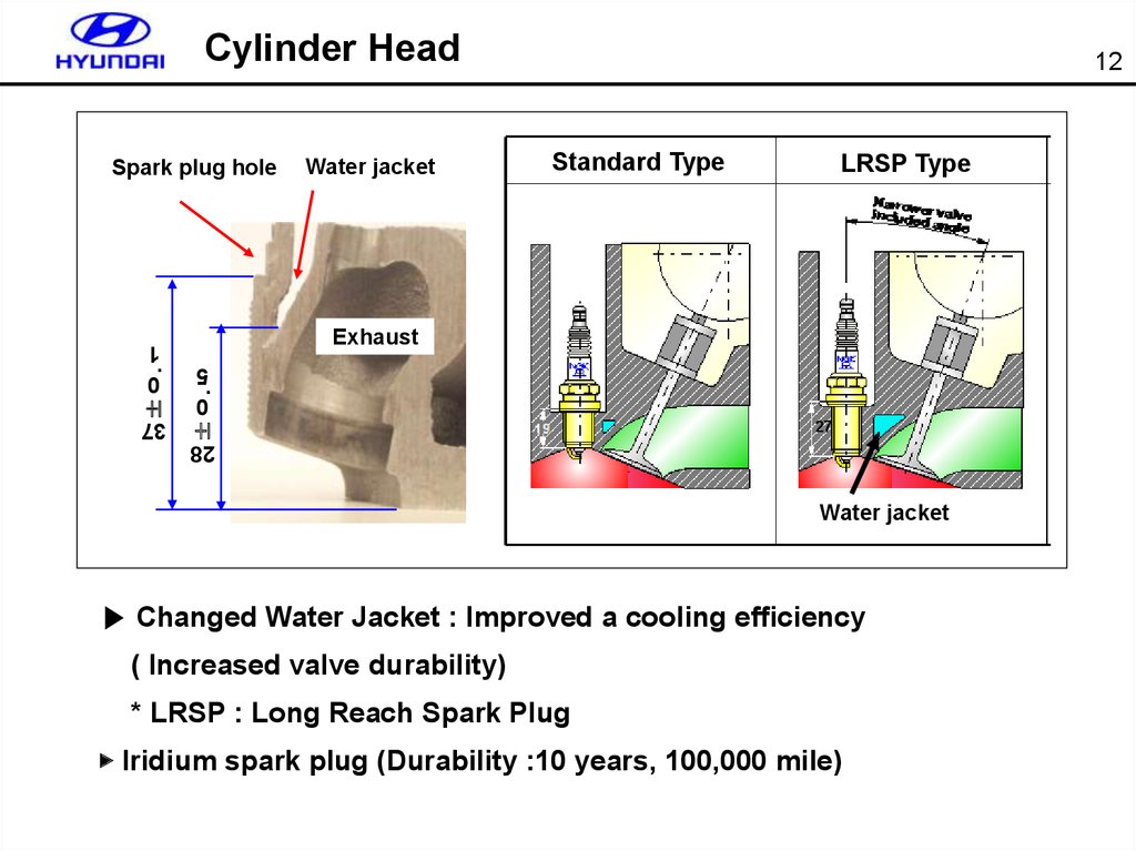
12.
Cylinder HeadSpark plug hole
LRSP Type
Exhaust
.
±
0
1
.
Standard Type
0
5
±
Water jacket
12
27
37
28
Water jacket
▶ Changed Water Jacket : Improved a cooling efficiency
( Increased valve durability)
* LRSP : Long Reach Spark Plug
▶ Iridium spark plug (Durability :10 years, 100,000 mile)
13.
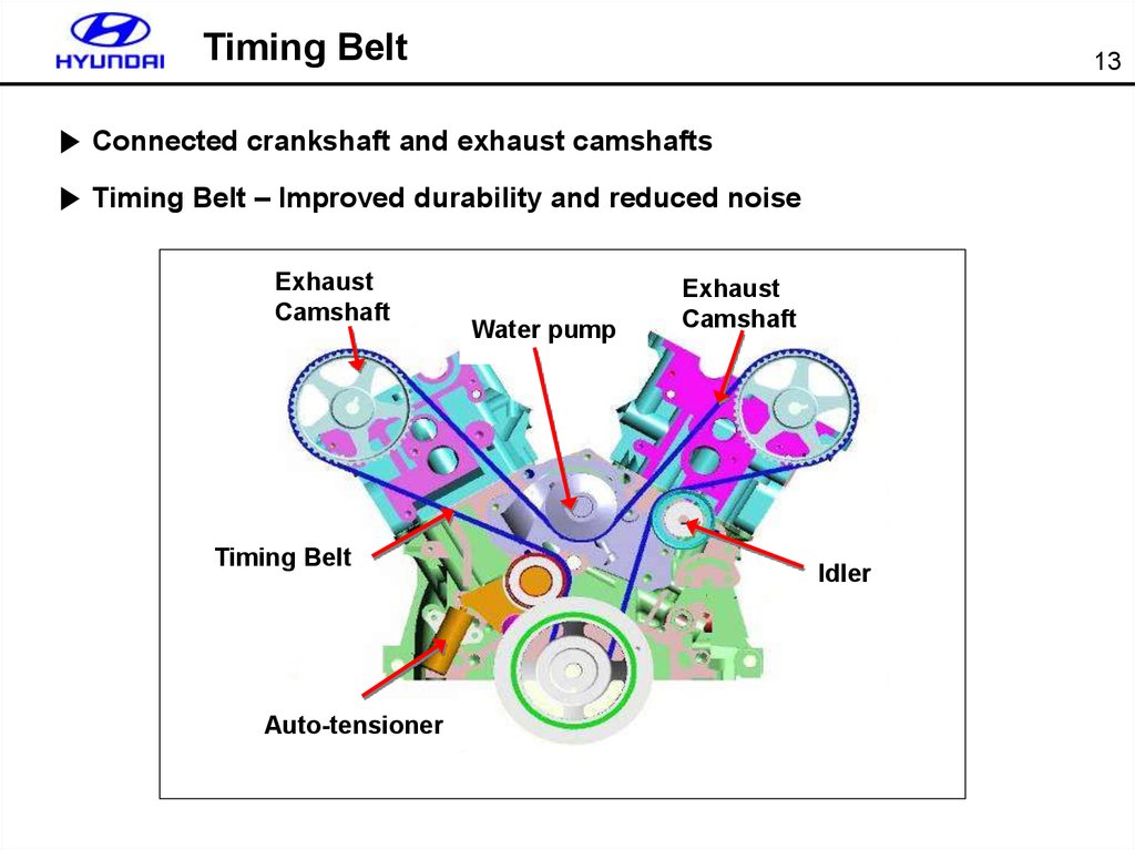
Timing Belt13
▶ Connected crankshaft and exhaust camshafts
▶ Timing Belt – Improved durability and reduced noise
Exhaust
Camshaft
Timing Belt
Auto-tensioner
Water pump
Exhaust
Camshaft
Idler
14.
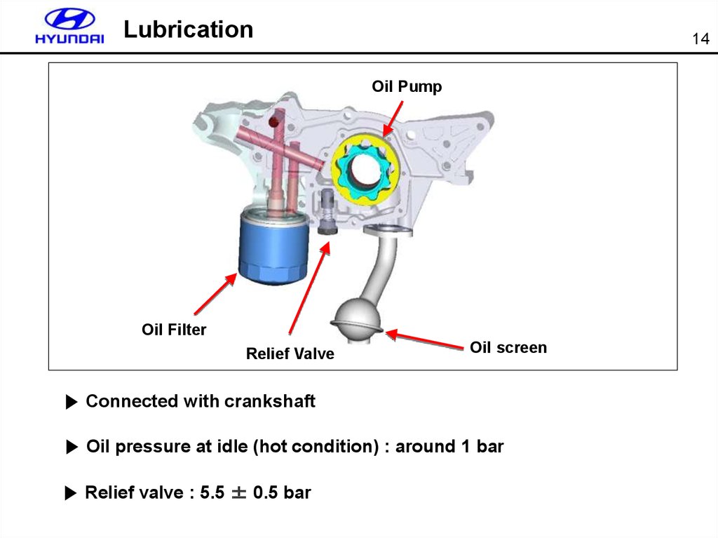
Lubrication14
Oil Pump
Oil Filter
Relief Valve
Oil screen
▶ Connected with crankshaft
▶ Oil pressure at idle (hot condition) : around 1 bar
▶ Relief valve : 5.5 ± 0.5 bar
15.
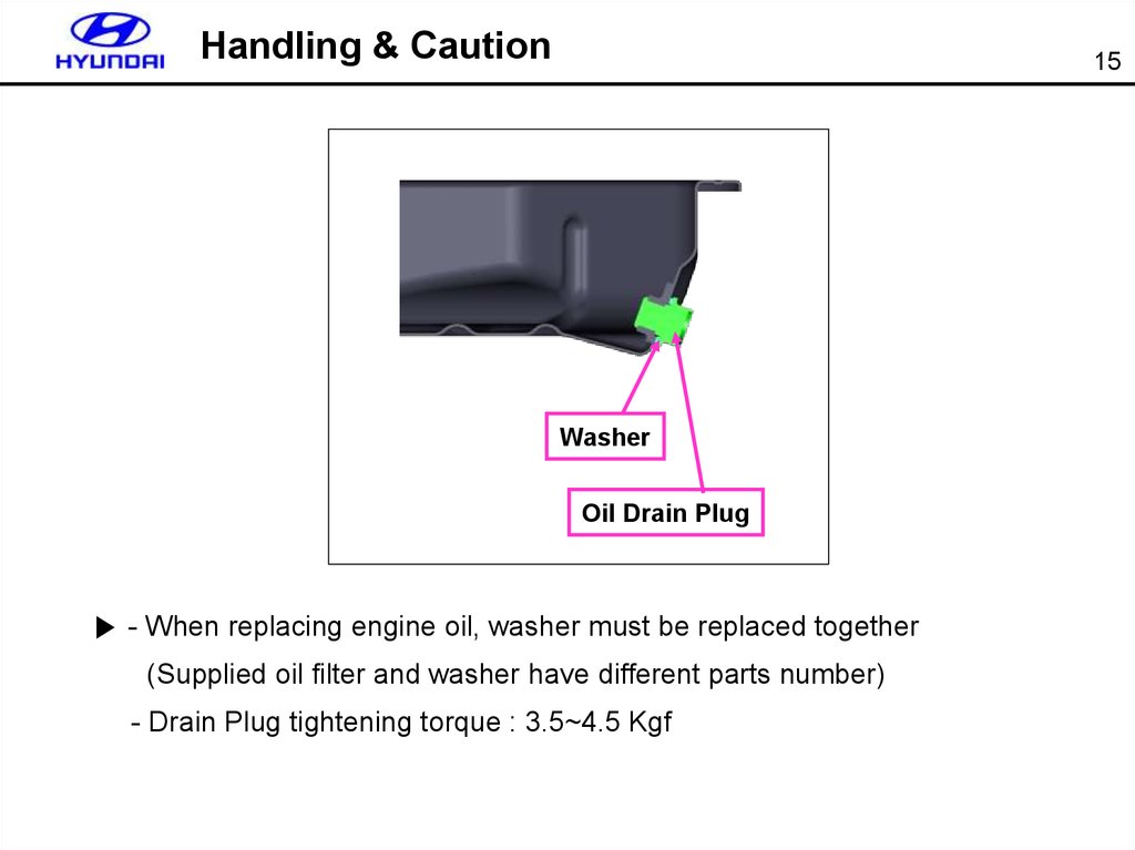
Handling & Caution15
Washer
Oil Drain Plug
▶ - When replacing engine oil, washer must be replaced together
(Supplied oil filter and washer have different parts number)
- Drain Plug tightening torque : 3.5~4.5 Kgf
16.
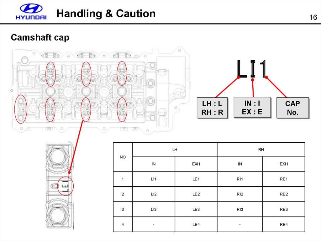
Handling & Caution16
Camshaft cap
LI1
IN : I
EX : E
LH : L
RH : R
LH
CAP
No.
RH
NO
IN
EXH
IN
EXH
1
LI1
LE1
RI1
RE1
2
LI2
LE2
RI2
RE2
3
LI3
LE3
RI3
RE3
4
-
LE4
-
RE4
17.
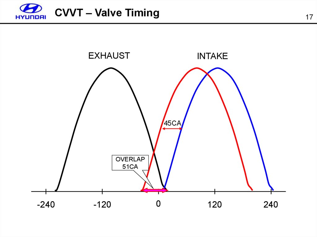
CVVT – Valve Timing17
EXHAUST
INTAKE
45CA
OVERLAP
51CA
-240
-120
0
120
240
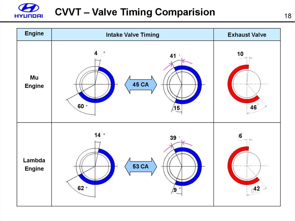
18.
CVVT – Valve Timing ComparisionEngine
Intake Valve Timing
4
Mu
Engine
18
Exhaust Valve
41
10
45 CA
60
14
Lambda
Engine
46
15
39
6
53 CA
62
9
42
19.
Fuel System – RLFS19
Fuel rail
■ Type : RLFS(Return Less Fuel System)
■ Regulated fuel pressure : 3.8kg/cm2
■ Fuel tank capacity : 75 L
■ Fuel cut speed at full load : 6688rpm
■ Damper on the fuel rail to prevent pulsation
Damper
Injector
Fuel tank
Fuel filter
Fuel
filter
Sub suction
Fuel pump
Regulator
Canister
Separator
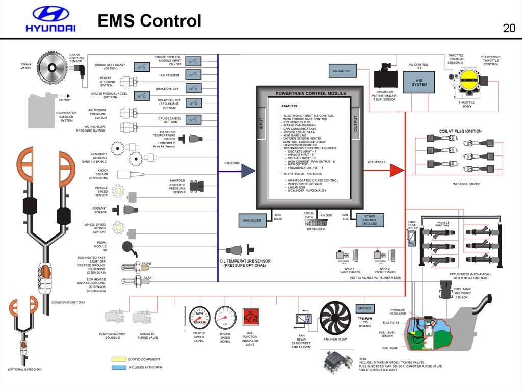
20.
EMS ControlCRANK
POSITION
SENSOR
CRANK
WHEEL
20
CRUISE CONTROL
MODULE INPUT
ON / OFF
CRUISE SET / COAST
(OPTION)
THROTTLE
POSITION
SENSOR(S)
VIS CONTROL
2X
A/C CLUTCH
ELECTRONIC
THROTTLE
CONTROL
AC REQUEST
POWER
STEERING
SWITCH
VIS
SYSTEM
BRAKE ON / OFF
CRUISE RESUME / ACCEL
(OPTION)
EVAPORATIVE
EMISSION
SYSTEM
AIR METER
WITH INTAKE AIR
TEMP. SENSOR
ENGINE CONTROL MODULE
BRAKE ON / OFF
(REDUNDANT)
(OPTION)
OUTPUT
A/C MEDIUM
PRESSURE
SWITCH
- ELECTRONIC THROTTLE CONTROL
WITH TORQUE BASE CONTROL
- RETURNLESS FUEL
- INTAKE CAM PHASING
- CAN COMMUNICATION
- KW2000 SERIAL DATA
- 4800 BAUD LINE
- OXYGEN SENSOR HEATER
CONTROL & CURRENT SENSE
- LOW POWER COUNTER
- TRANSMISSION CONTROL INCLUDES:
- DISCRETE INPUT - 7
- ANALOG INPUT - 1
- VR / HALL INPUT - 2
- HIGH CURRENT PWM OUTPUT - 6
- PWM OUTPUT - 1
- FREQUENCY OUTPUT - 1
CRUISE CANCEL
(OPTION)
A/C HIGH/LOW
PRESSURE SWITCH
INTAKE AIR
TEMPERATURE
SENSOR
(Integrated in
Mass Air Sensor)
CAMSHAFT
SENSORS
BANK 1 & BANK 2
SENSORS
KNOCK
SENSOR
(2 SENSORS)
THROTTLE
BODY
-FEATURES:
COIL AT PLUG IGNITION
ACTUATORS
- KEY OPTIONAL FEATURES
MANIFOLD
ABSOLUTE
PRESSURE
SENSOR
VEHICLE
SPEED
SENSOR
-
COOLANT
SENSOR
IMMOBILIZER
4800
BAUD
WHEEL SPEED
SENSOR
(OPTION)
UP-INTEGRATED CRUISE CONTROL
WHEEL SPEED SENSOR
LINEAR EGR
8-CYLINDER FUNC
TIONALITY
SERIAL
DATA
KW 2000
WITH COIL DRIVER
CAN
BUS
OTHER
CONTROL
MODULES
DIAGNOSTIC
FUEL
PUMP
RELAY
PEDAL
MODULE
2X
ECM HEATED FAST
LIGHT-OFF
ISOLATED GROUND
O2 SENSOR
(2 SENSORS)
ECM HEATED
ISOLATED GROUND
O2 SENSOR
(2 SENSORS)
OIL TEMPERATURE SENSOR
(PRESSURE OPTIONAL)
FRONT
BANK 1
VANE PHASER
REAR
RETURNLESS (MECHANICAL)
SEQUENTIAL FUEL RAIL
FUEL TANK
PRESSURE
SENSOR
3
EPS/ECS
EPS/ECS
4
2
5
6
1
0
TPS PWM
TO
EPS/ECS
7
x 1000
CANISTER
PURGE VALVE
QUOTED COMPONENT
(OPTIONAL BY REGION)
BANK 2
VANE PHASER
(NOT AVAILABLE WITH LINEAR EGR)
Thermostat
EVAP DIAGNOSTIC
SOLENOID
CVCP CONTROL
VALVE
CVCP CONTROL
VALVE
INCLUDED IN THE IAFM
THERMOSTAT
CONTROL
VEHICLE
SPEED
SIGNAL
ENGINE
SPEED
SIGNAL
MALFUNCTION
INDICATOR
LIGHT
FUEL
LEVEL
SIGNAL
FAN
RELAY
2X DISCRETE
AND 1X PWM
FAN HIGH / LOW
IAFM
INCLUDE: INTAKE MANIFOLD, TUNING VALVES,
FUEL INJECTORS, MAP SENSOR, CANISTER PURGE VALVE
AND ETC THROTTLE BODY
21.
EMS General21
Specification
BTDC 10O ± 5O
Ignition timing
A/CON OFF
Idle rpm
A/CON ON
P/N
D
P/N
D
650 ± 100
650 ± 100
650 ± 100
650 ± 100
EMS
Delphi/ 32bit ECU
CKPS
VR type (Engine can start even in case of CKP failure)
CMPS
Hall IC type
Ignition
DLI (firing order : 2-3-4-5-6-1)
Cooling Fan
CAN
MAF
(IAT built-in type)
O2 sensor
Low/High speed control
PCM-ESP-4WD
Hot film type 5PIN (3PIN :MAF, 2PIN:ATS)
Zirconia type (4EA)
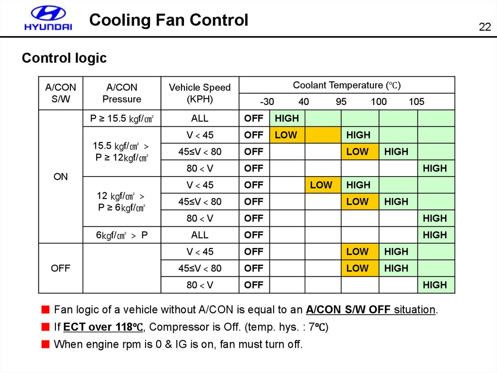
22.
Cooling Fan Control22
Control logic
A/CON
S/W
Vehicle Speed
(KPH)
P ≥ 15.5 ㎏f/㎠
ALL
OFF
HIGH
V 45
OFF
LOW
45≤V 80
OFF
80 V
OFF
V 45
OFF
45≤V 80
OFF
80 V
OFF
HIGH
ALL
OFF
HIGH
V 45
OFF
LOW
HIGH
45≤V 80
OFF
LOW
HIGH
80 V
OFF
15.5 ㎏f/㎠
P ≥ 12㎏f/㎠
ON
12 ㎏f/㎠
P ≥ 6㎏f/㎠
6㎏f/㎠ P
OFF
Coolant Temperature (℃)
A/CON
Pressure
-30
40
95
100
105
HIGH
LOW
HIGH
HIGH
LOW
HIGH
LOW
HIGH
HIGH
■ Fan logic of a vehicle without A/CON is equal to an A/CON S/W OFF situation.
■ If ECT over 118℃, Compressor is Off. (temp. hys. : 7℃)
■ When engine rpm is 0 & IG is on, fan must turn off.
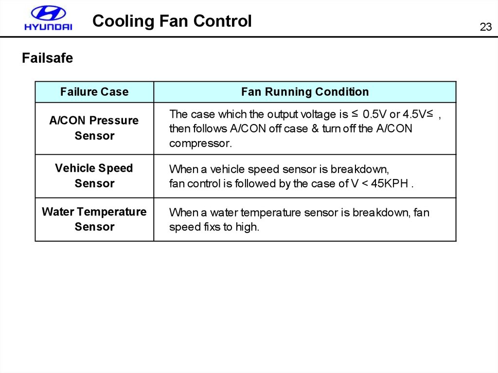
23.
Cooling Fan ControlFailsafe
Failure Case
Fan Running Condition
A/CON Pressure
Sensor
The case which the output voltage is ≤ 0.5V or 4.5V ≤ ,
then follows A/CON off case & turn off the A/CON
compressor.
Vehicle Speed
Sensor
Water Temperature
Sensor
When a vehicle speed sensor is breakdown,
fan control is followed by the case of V < 45KPH .
When a water temperature sensor is breakdown, fan
speed fixs to high.
23
24.
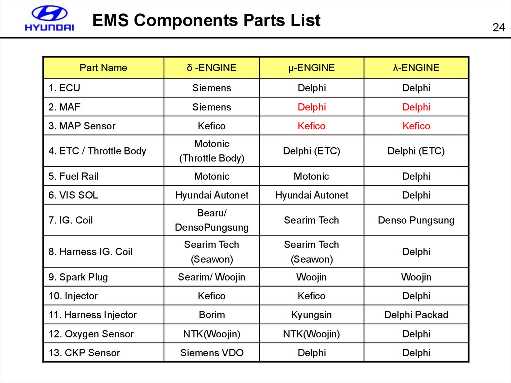
EMS Components Parts List24
δ -ENGINE
μ-ENGINE
λ-ENGINE
1. ECU
Siemens
Delphi
Delphi
2. MAF
Siemens
Delphi
Delphi
Kefico
Kefico
Kefico
Motonic
(Throttle Body)
Delphi (ETC)
Delphi (ETC)
5. Fuel Rail
Motonic
Motonic
Delphi
6. VIS SOL
Hyundai Autonet
Hyundai Autonet
Delphi
7. IG. Coil
Bearu/
DensoPungsung
Searim Tech
Denso Pungsung
Searim Tech
(Seawon)
Searim Tech
(Seawon)
Delphi
Searim/ Woojin
Woojin
Woojin
10. Injector
Kefico
Kefico
Delphi
11. Harness Injector
Borim
Kyungsin
Delphi Packad
12. Oxygen Sensor
NTK(Woojin)
NTK(Woojin)
Delphi
13. CKP Sensor
Siemens VDO
Delphi
Delphi
Part Name
3. MAP Sensor
4. ETC / Throttle Body
8. Harness IG. Coil
9. Spark Plug
25.
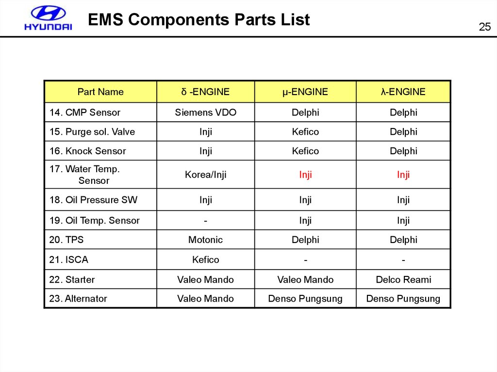
EMS Components Parts List25
δ -ENGINE
μ-ENGINE
λ-ENGINE
Siemens VDO
Delphi
Delphi
15. Purge sol. Valve
Inji
Kefico
Delphi
16. Knock Sensor
Inji
Kefico
Delphi
Korea/Inji
Inji
Inji
18. Oil Pressure SW
Inji
Inji
Inji
19. Oil Temp. Sensor
-
Inji
Inji
20. TPS
Motonic
Delphi
Delphi
21. ISCA
Kefico
-
-
22. Starter
Valeo Mando
Valeo Mando
Delco Reami
23. Alternator
Valeo Mando
Denso Pungsung
Denso Pungsung
Part Name
14. CMP Sensor
17. Water Temp.
Sensor
26.
EMS Components Parts List26
For Mu enigine
Part Name
Supplier
Part Number
Remark
1. MAF
Delphi
28164-3C100
Same as Lamda
2. MAP Sensor
Kefico
39300-38200
Same as Lamda
3. ETC
Delphi
35100-3E100
-
4. Fuel Injector
Kefico
35310-23600
-
5. VIS SOL
Hyundai Autonet
39460-37000
-
6. IG. Coil
Searim Tech
27301-3E100
-
Woojin
18840-11051
-
NTK(Woojin)
39210-3E110
-
9. CKP Sensor
Delphi
39180-3E100
-
10. CMP Sensor
Delphi
39350-3E110(RH)
39350-3E120(LH)
-
11. PCSV
Kefico
28910-3E100
-
12. Knock Sensor
Kefico
39250-3E110
-
13. WTS
Inji
39220-38030
Same as Lamda
14. OPS
Inji
94750-37000
-
15. OTS
Inji
39220-3C100
-
7. Spark Plug
8. Oxygen Sensor
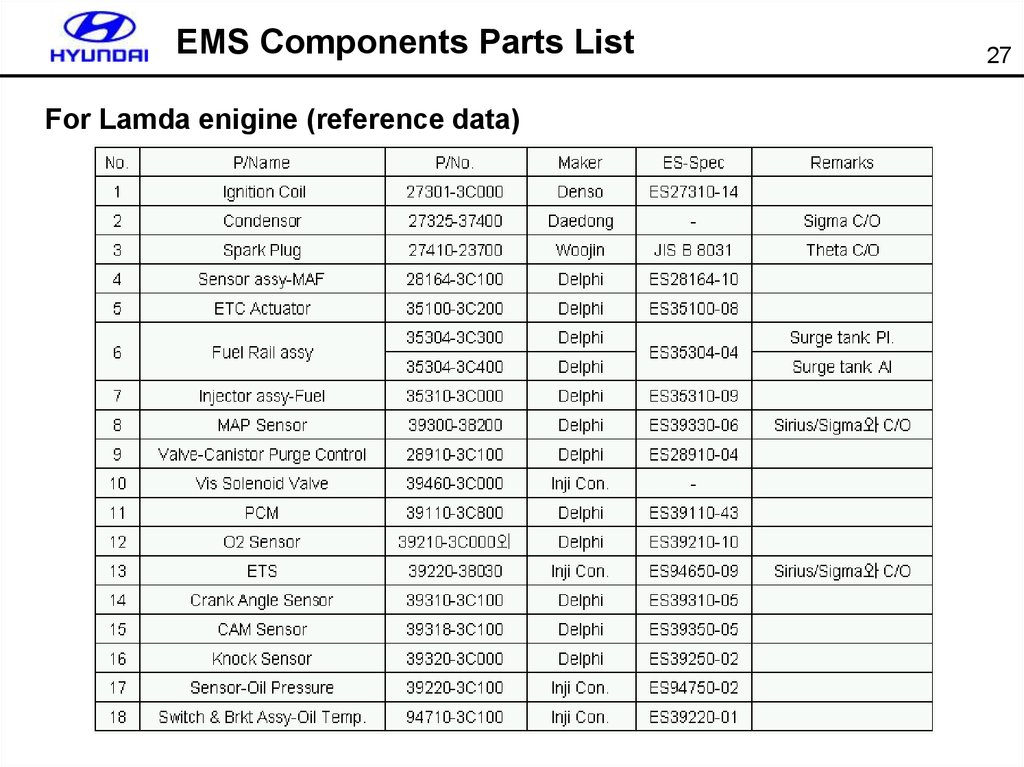
27.
EMS Components Parts ListFor Lamda enigine (reference data)
27
28.
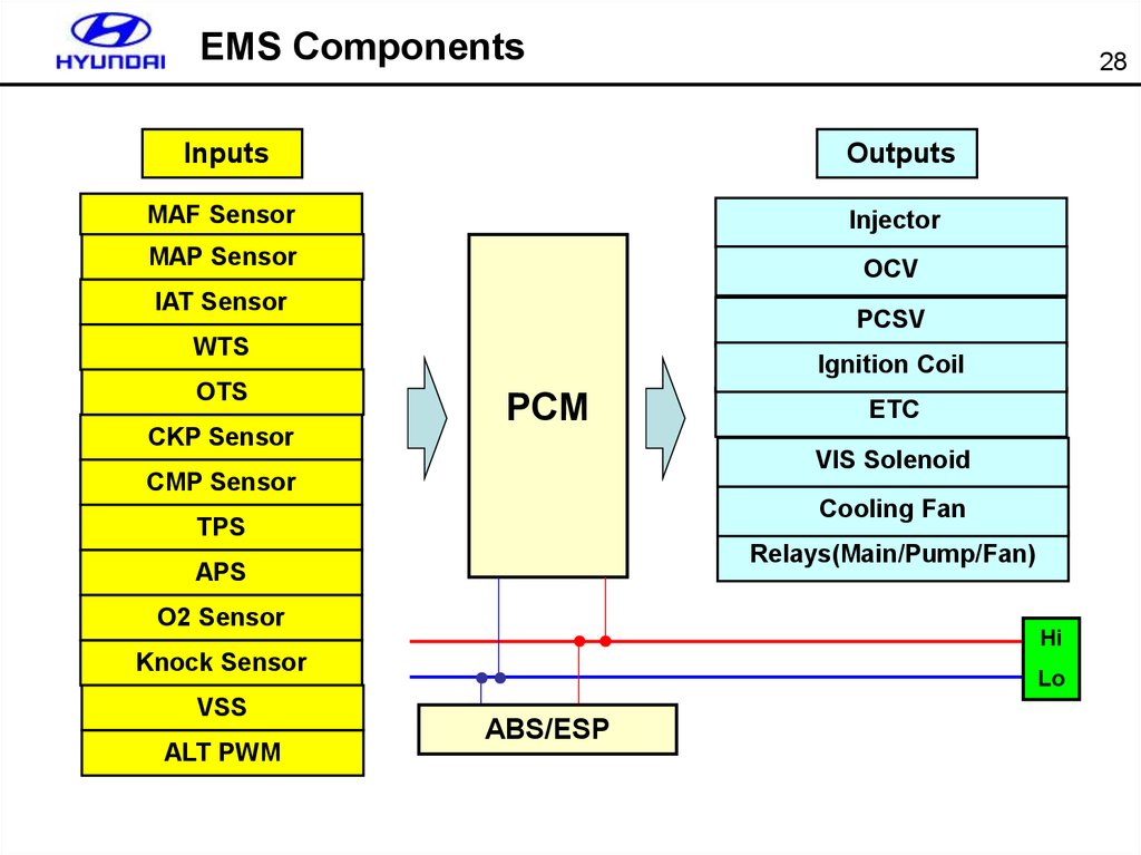
EMS Components28
Inputs
Outputs
MAF Sensor
Injector
MAP Sensor
OCV
IAT Sensor
PCSV
WTS
OTS
CKP Sensor
Ignition Coil
PCM
VIS Solenoid
CMP Sensor
Cooling Fan
TPS
Relays(Main/Pump/Fan)
APS
O2 Sensor
Hi
Knock Sensor
VSS
ALT PWM
ETC
Lo
ABS/ESP
29.
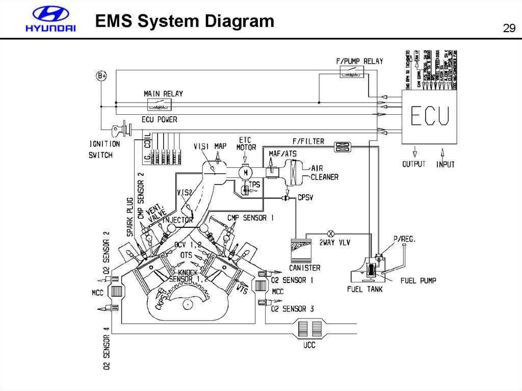
EMS System Diagram29
30.
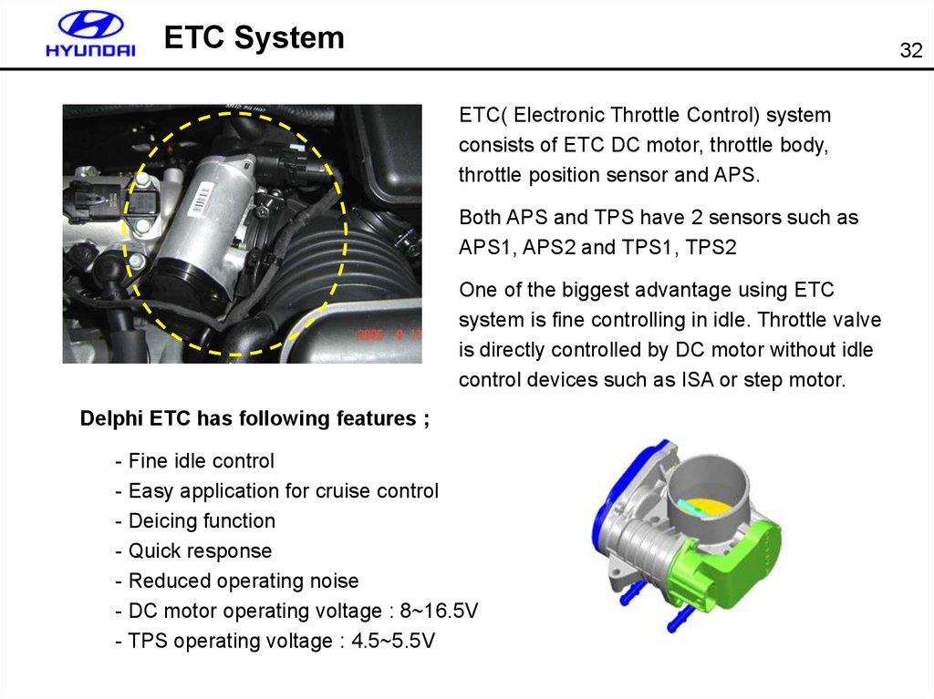
ETC System32
ETC( Electronic Throttle Control) system
consists of ETC DC motor, throttle body,
throttle position sensor and APS.
Both APS and TPS have 2 sensors such as
APS1, APS2 and TPS1, TPS2
One of the biggest advantage using ETC
system is fine controlling in idle. Throttle valve
is directly controlled by DC motor without idle
control devices such as ISA or step motor.
Delphi ETC has following features ;
- Fine idle control
- Easy application for cruise control
- Deicing function
- Quick response
- Reduced operating noise
- DC motor operating voltage : 8~16.5V
- TPS operating voltage : 4.5~5.5V
31.
ETC System33
System layout
APS1,2
PCM
Electronic Throttle Body
Motor Drive
Driver’s
intension
Position
Feedback
(TPS1,2)
CAN
Torque
reduction
request
ESP unit
Position sensor
32.
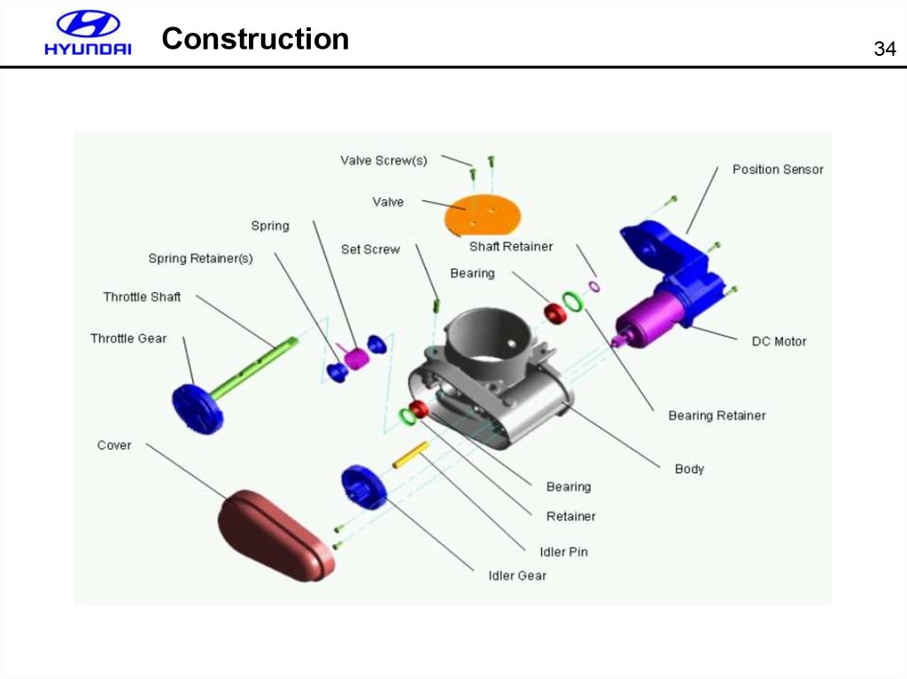
Construction34
33.
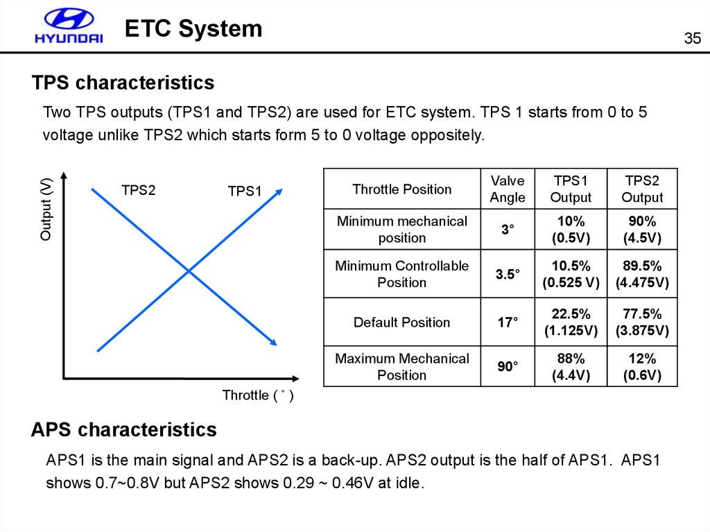
ETC System35
TPS characteristics
Output (V)
Two TPS outputs (TPS1 and TPS2) are used for ETC system. TPS 1 starts from 0 to 5
voltage unlike TPS2 which starts form 5 to 0 voltage oppositely.
TPS2
TPS1
Throttle Position
Valve
Angle
TPS1
Output
TPS2
Output
Minimum mechanical
position
3°
10%
(0.5V)
90%
(4.5V)
Minimum Controllable
Position
3.5°
10.5%
(0.525 V)
89.5%
(4.475V)
Default Position
17°
22.5%
(1.125V)
77.5%
(3.875V)
Maximum Mechanical
Position
90°
88%
(4.4V)
12%
(0.6V)
Throttle ( ˚ )
APS characteristics
APS1 is the main signal and APS2 is a back-up. APS2 output is the half of APS1. APS1
shows 0.7~0.8V but APS2 shows 0.29 ~ 0.46V at idle.
34.
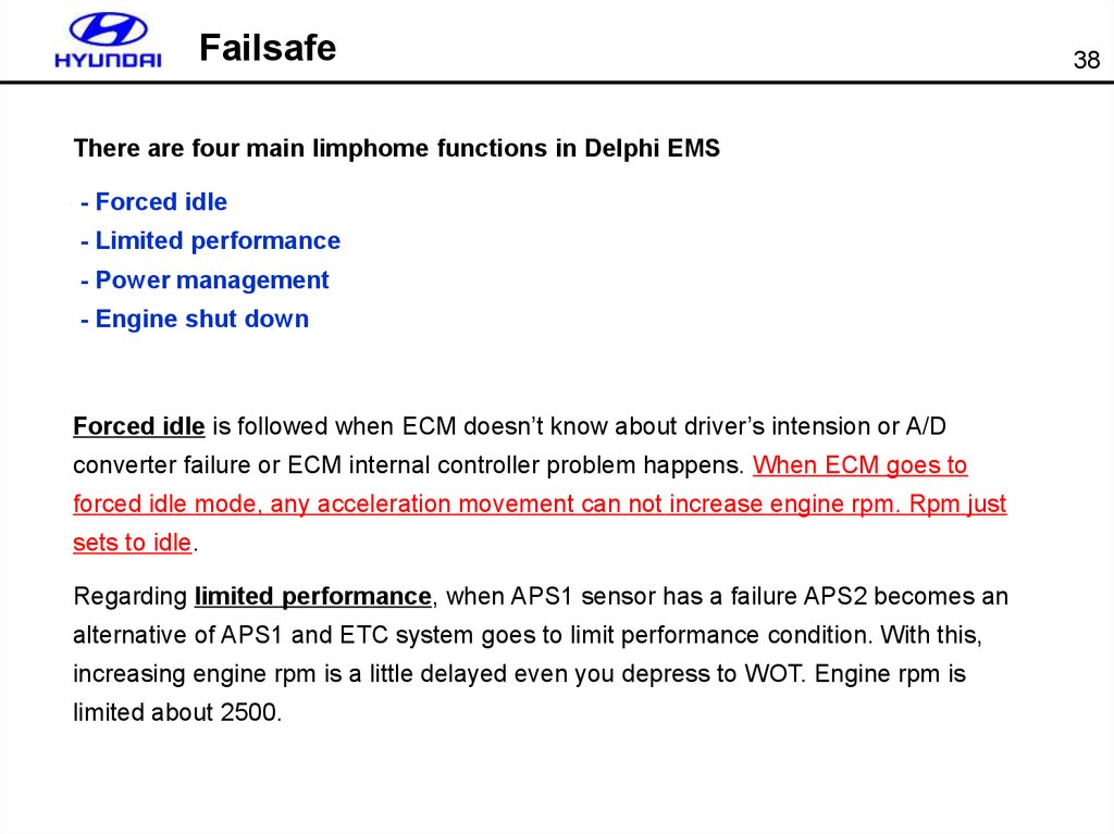
FailsafeThere are four main limphome functions in Delphi EMS
- Forced idle
- Limited performance
- Power management
- Engine shut down
Forced idle is followed when ECM doesn’t know about driver’s intension or A/D
converter failure or ECM internal controller problem happens. When ECM goes to
forced idle mode, any acceleration movement can not increase engine rpm. Rpm just
sets to idle.
Regarding limited performance, when APS1 sensor has a failure APS2 becomes an
alternative of APS1 and ETC system goes to limit performance condition. With this,
increasing engine rpm is a little delayed even you depress to WOT. Engine rpm is
limited about 2500.
38
35.
FailsafeUnlike forced idle, power management is followed mainly from TPS failure. Since now
ECM doesn’t have any information from TPS, engine rpm and MAF value are used for
feedback control. Under this power management condition, fuel cutting for specified
cylinder and igntion timing retard happens resulting in rough idling and fluctuating.
engine rpm is limited by 1800..
Engine shut down generally happens when you have TPS or DC motor problem with
MAP&MAF failure. When this problem is detected, engine immediately shuts down.
39
36.
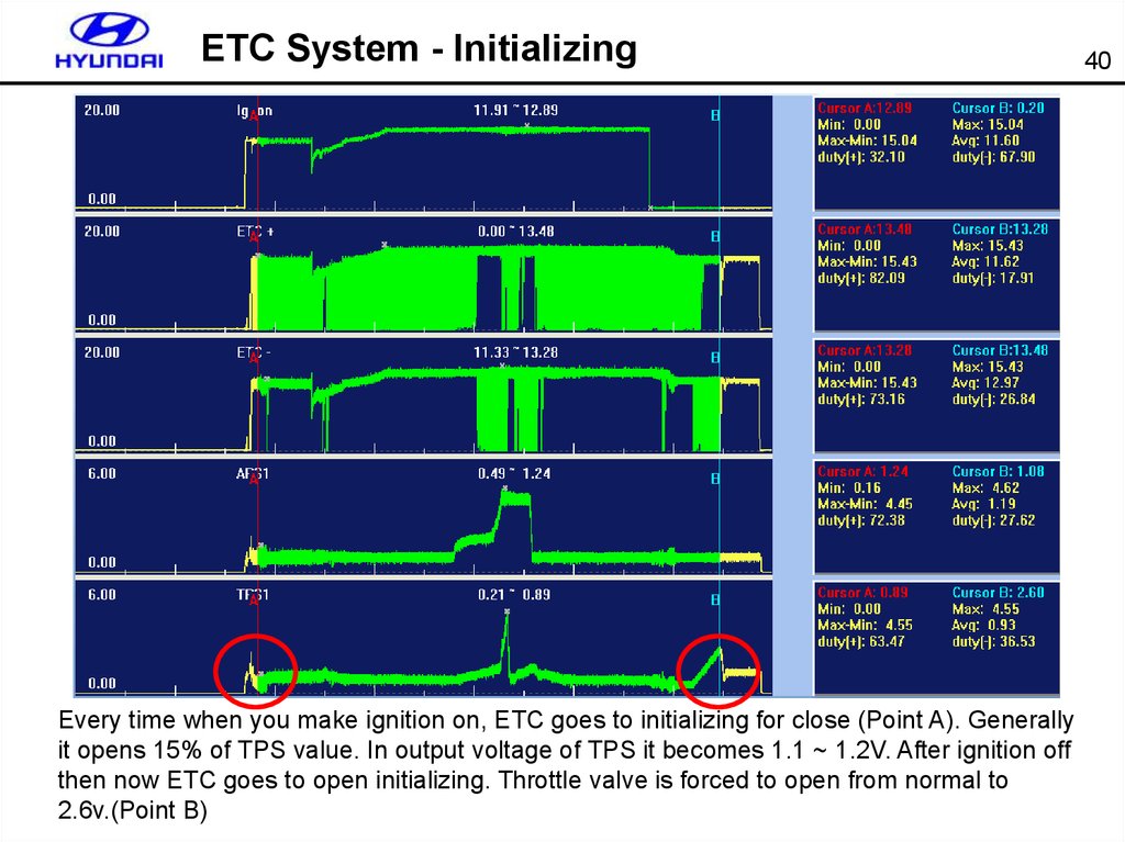
ETC System - InitializingEvery time when you make ignition on, ETC goes to initializing for close (Point A). Generally
it opens 15% of TPS value. In output voltage of TPS it becomes 1.1 ~ 1.2V. After ignition off
then now ETC goes to open initializing. Throttle valve is forced to open from normal to
2.6v.(Point B)
40
37.
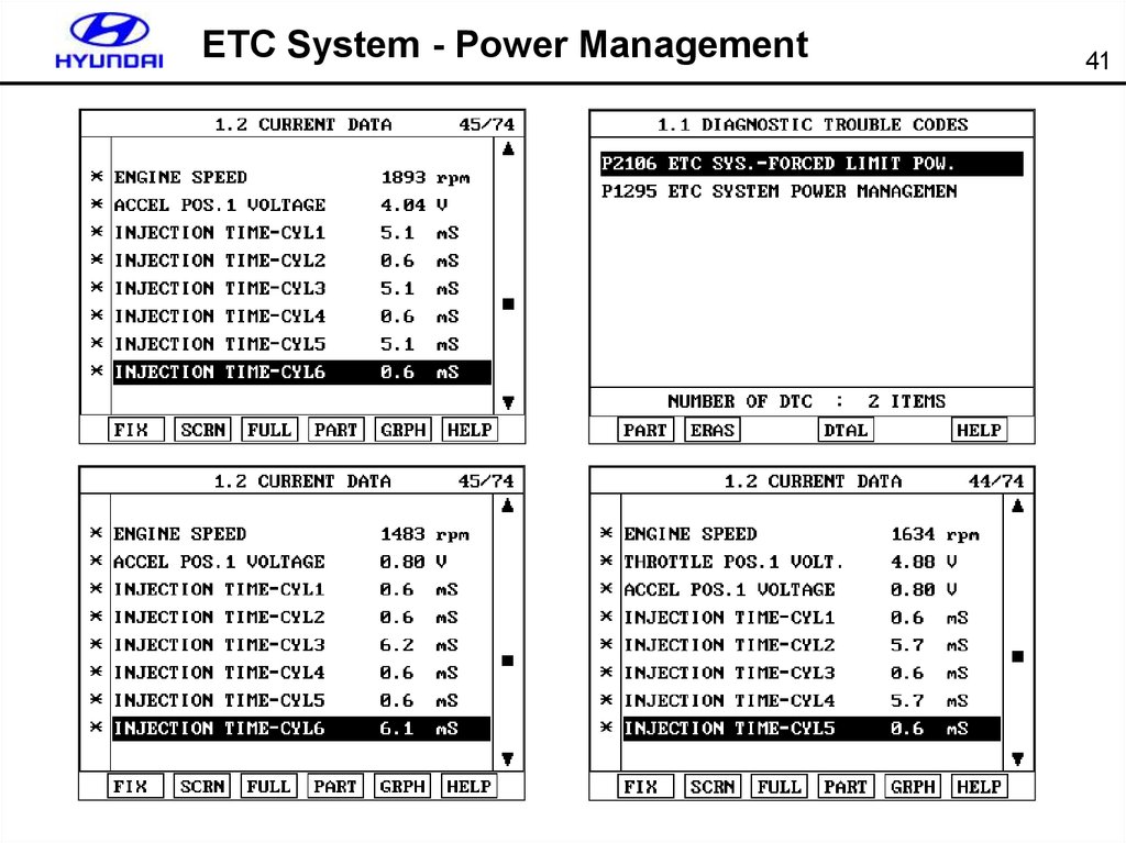
ETC System - Power Management41
38.
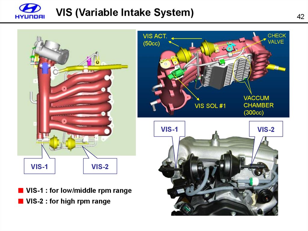
VIS (Variable Intake System)42
CHECK
VALVE
VIS ACT.
(50cc)
VIS SOL #1
VIS-1
VIS-1
VIS-2
■ VIS-1 : for low/middle rpm range
■ VIS-2 : for high rpm range
VACCUM
CHAMBER
(300cc)
VIS-2
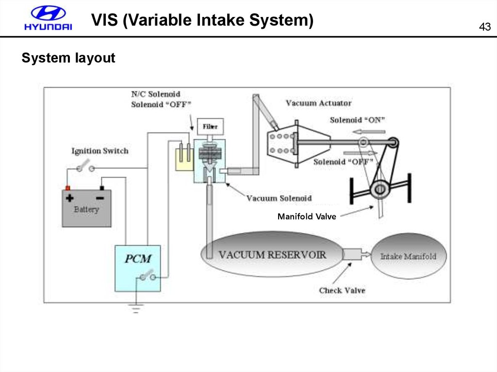
39.
VIS (Variable Intake System)System layout
Manifold Valve
43
40.
VIS (Variable Intake System)44
Solenoid
Diaphram
Technical feature
- Type : 3 way valve
- Coil resistance : 32±3 Ω (at 20℃)
Vacuum
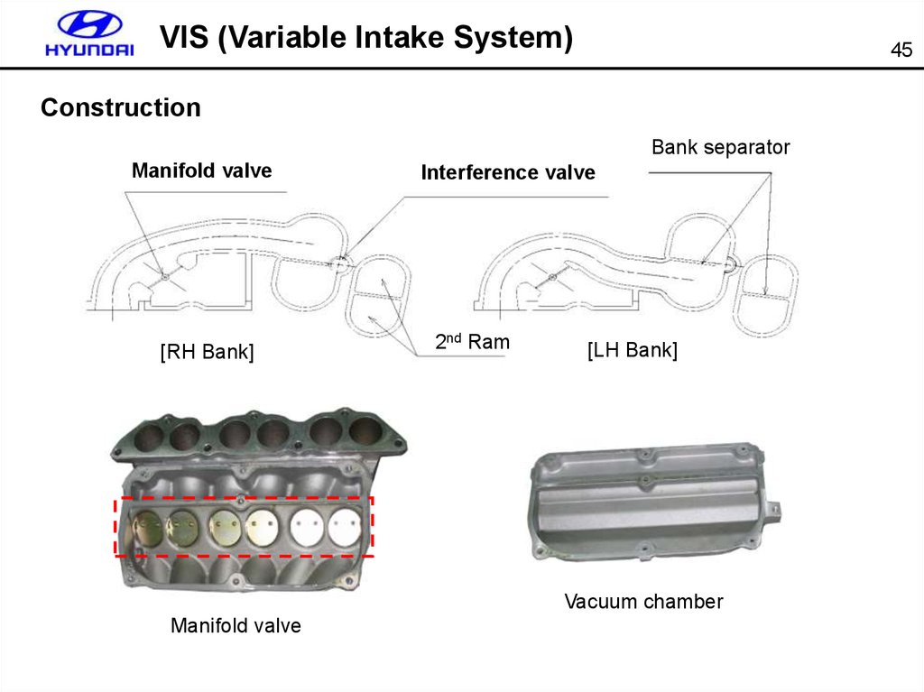
41.
VIS (Variable Intake System)45
Construction
Bank separator
Manifold valve
[RH Bank]
Interference valve
2nd Ram
[LH Bank]
Vacuum chamber
Manifold valve
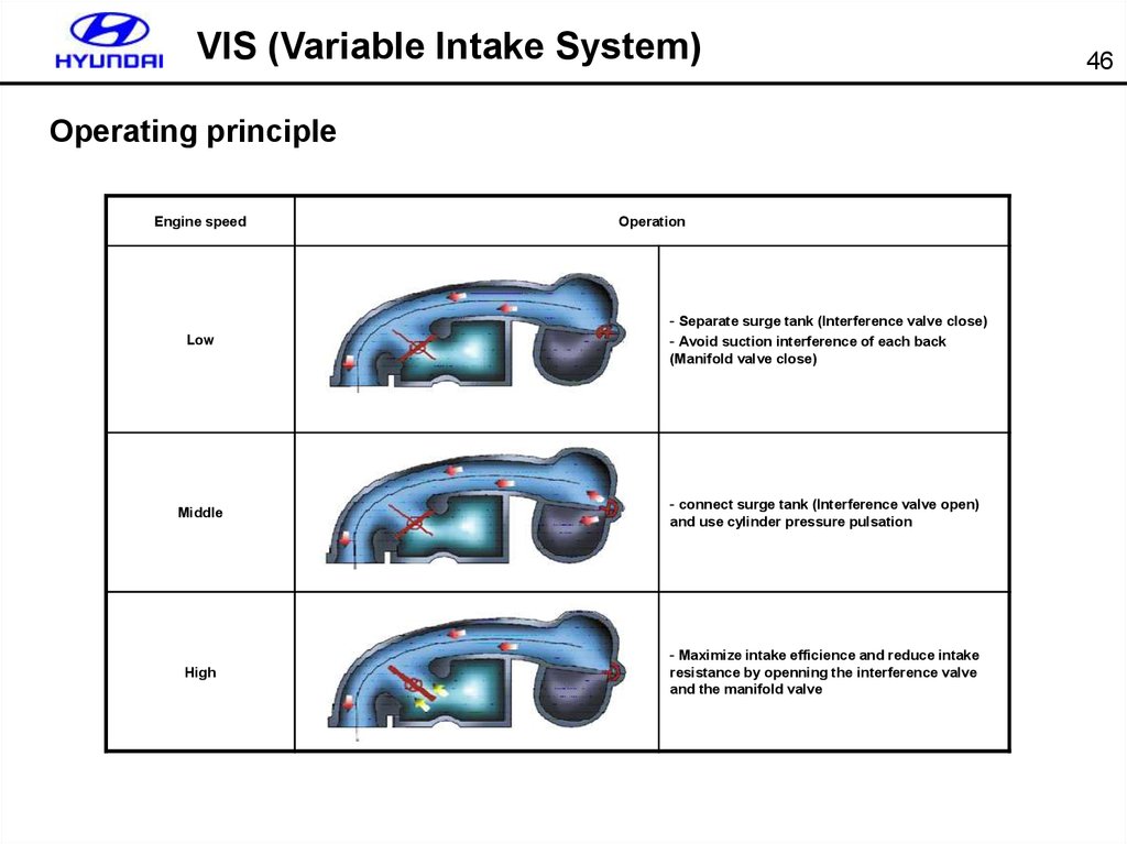
42.
VIS (Variable Intake System)Operating principle
Engine speed
Operation
Low
- Separate surge tank (Interference valve close)
- Avoid suction interference of each back
(Manifold valve close)
Middle
- connect surge tank (Interference valve open)
and use cylinder pressure pulsation
High
- Maximize intake efficience and reduce intake
resistance by openning the interference valve
and the manifold valve
46
43.
VIS (Variable Intake System)47
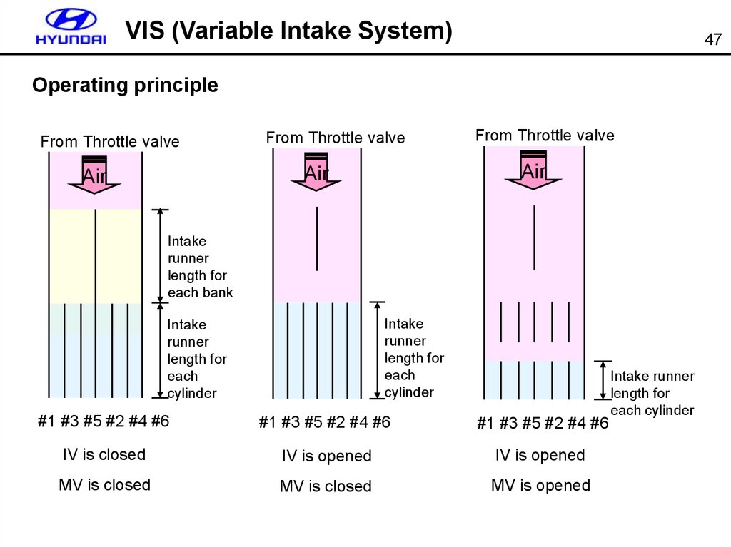
Operating principle
From Throttle valve
From Throttle valve
Air
Air
Air
From Throttle valve
Intake
runner
length for
each bank
Intake
runner
length for
each
cylinder
Intake
runner
length for
each
cylinder
#1 #3 #5 #2 #4 #6
#1 #3 #5 #2 #4 #6
#1 #3 #5 #2 #4 #6
IV is closed
IV is opened
IV is opened
MV is closed
MV is closed
MV is opened
Intake runner
length for
each cylinder
44.
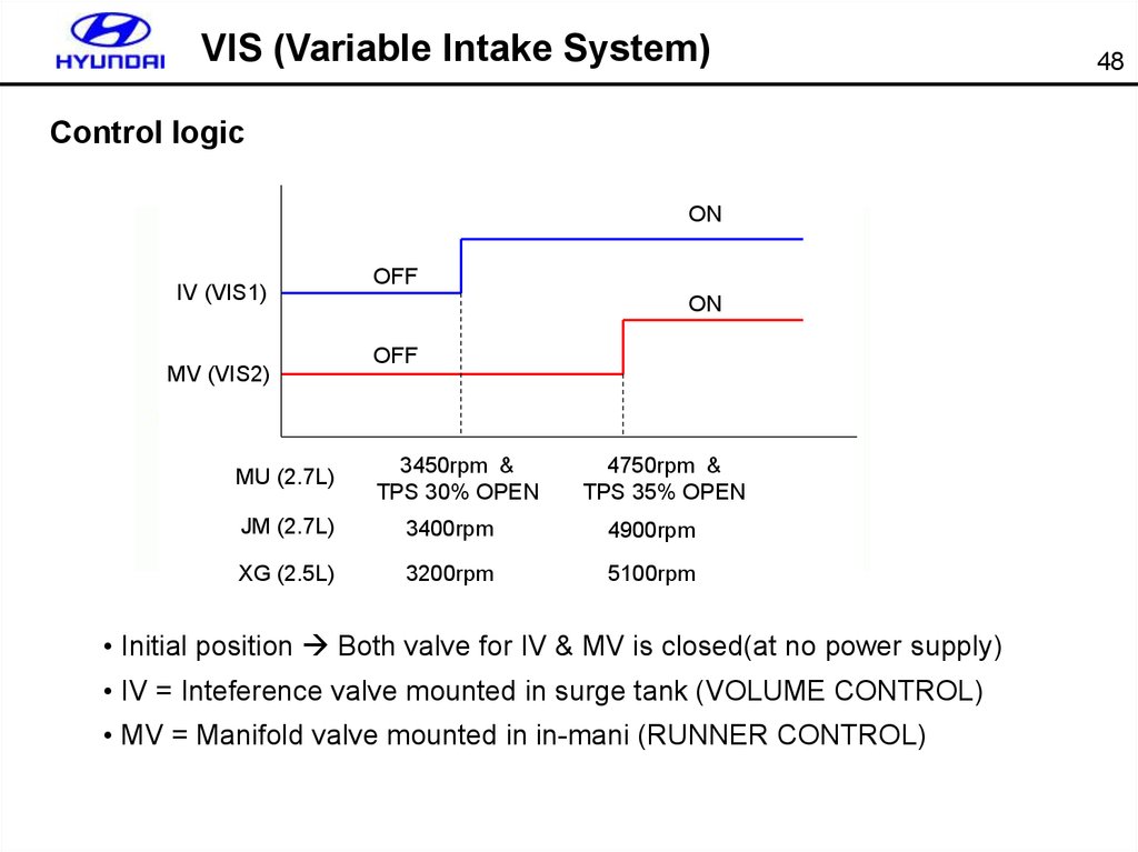
VIS (Variable Intake System)Control logic
ON
IV (VIS1)
MV (VIS2)
MU (2.7L)
OFF
ON
OFF
3450rpm &
TPS 30% OPEN
4750rpm &
TPS 35% OPEN
JM (2.7L)
3400rpm
4900rpm
XG (2.5L)
3200rpm
5100rpm
• Initial position Both valve for IV & MV is closed(at no power supply)
• IV = Inteference valve mounted in surge tank (VOLUME CONTROL)
• MV = Manifold valve mounted in in-mani (RUNNER CONTROL)
48
45.
VIS (Variable Intake System)49
Solenoid output (Sudden acceleration)
Solenoid_VIS1 (Interference valve)
OFF
a
ON
• a: IV-ON, MV-OFF
TPS > 30%, 3450 ~ 4750 (rpm)
30% < TPS < 35%, > 3450 (rpm)
Solenoid_VIS2 (Manifold valve)
OFF
OFF
b
ON
• b: IV-ON, MV-ON
TPS > 35%, > 4750 (rpm)
46.
VIS (Variable Intake System)50
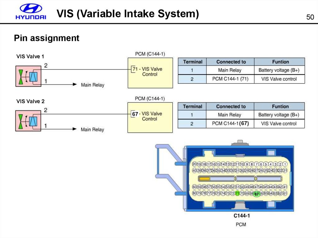
Pin assignment
VIS Valve 1
VIS Valve 2
67
(67)
67
47.
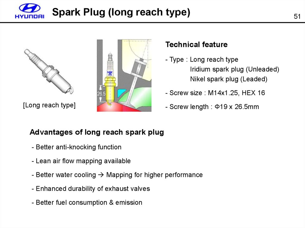
Spark Plug (long reach type)Technical feature
- Type : Long reach type
Iridium spark plug (Unleaded)
Nikel spark plug (Leaded)
- Screw size : M14x1.25, HEX 16
[Long reach type]
- Screw length : Φ19 x 26.5mm
Advantages of long reach spark plug
- Better anti-knocking function
- Lean air flow mapping available
- Better water cooling Mapping for higher performance
- Enhanced durability of exhaust valves
- Better fuel consumption & emission
51
48.
CKP Sensor52
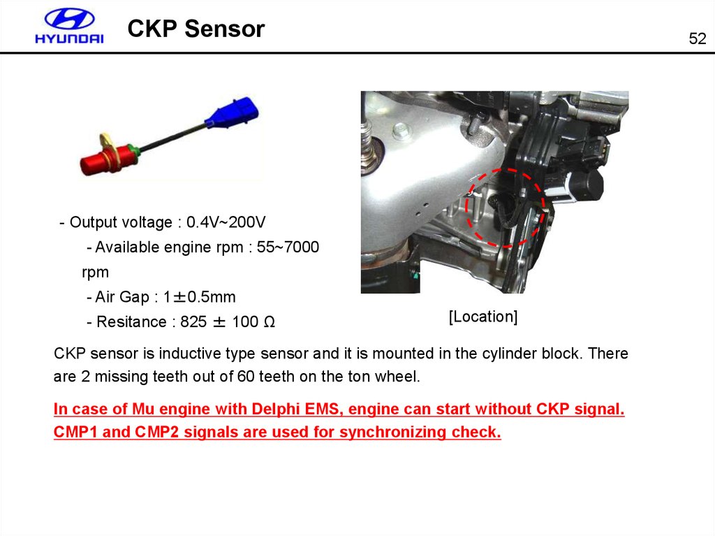
- Output voltage : 0.4V~200V
- Available engine rpm : 55~7000
rpm
- Air Gap : 1±0.5mm
- Resitance : 825 ± 100 Ω
[Location]
CKP sensor is inductive type sensor and it is mounted in the cylinder block. There
are 2 missing teeth out of 60 teeth on the ton wheel.
In case of Mu engine with Delphi EMS, engine can start without CKP signal.
CMP1 and CMP2 signals are used for synchronizing check.
49.
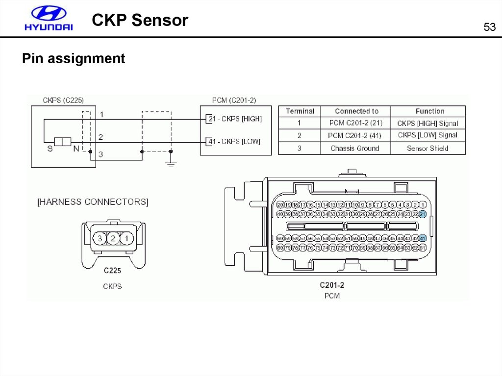
CKP SensorPin assignment
53
50.
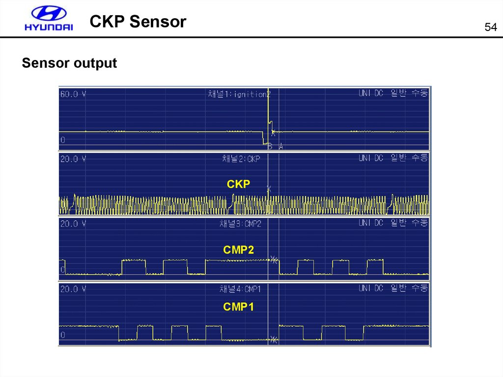
CKP Sensor54
Sensor output
CKP
CMP2
CMP1
51.
CMP Sensor55
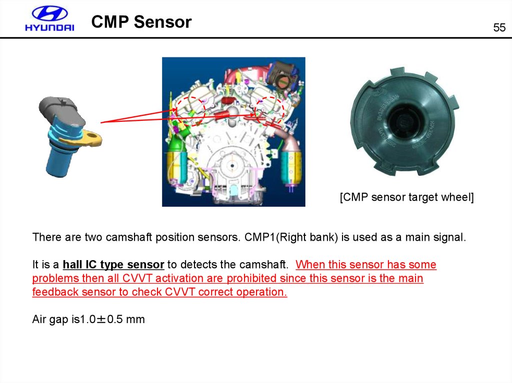
[CMP sensor target wheel]
There are two camshaft position sensors. CMP1(Right bank) is used as a main signal.
It is a hall IC type sensor to detects the camshaft. When this sensor has some
problems then all CVVT activation are prohibited since this sensor is the main
feedback sensor to check CVVT correct operation.
Air gap is1.0±0.5 mm
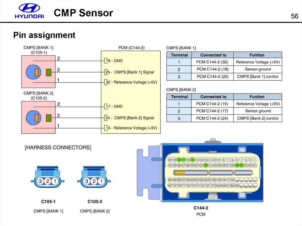
52.
CMP SensorPin assignment
56
53.
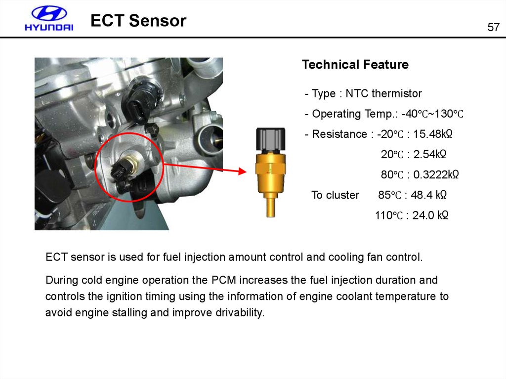
ECT Sensor57
Technical Feature
- Type : NTC thermistor
- Operating Temp.: -40℃~130℃
- Resistance : -20℃ : 15.48㏀
20℃ : 2.54㏀
80℃ : 0.3222㏀
To cluster
85℃ : 48.4 ㏀
110℃ : 24.0 ㏀
ECT sensor is used for fuel injection amount control and cooling fan control.
During cold engine operation the PCM increases the fuel injection duration and
controls the ignition timing using the information of engine coolant temperature to
avoid engine stalling and improve drivability.
54.
ECT Sensor58
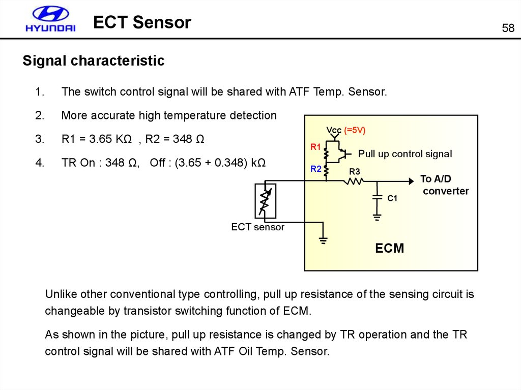
Signal characteristic
1.
The switch control signal will be shared with ATF Temp. Sensor.
2.
More accurate high temperature detection
3.
R1 = 3.65 KΩ , R2 = 348 Ω
4.
TR On : 348 Ω, Off : (3.65 + 0.348) kΩ
Vcc (=5V)
R1
R2
Pull up control signal
R3
C1
To A/D
converter
ECT sensor
ECM
Unlike other conventional type controlling, pull up resistance of the sensing circuit is
changeable by transistor switching function of ECM.
As shown in the picture, pull up resistance is changed by TR operation and the TR
control signal will be shared with ATF Oil Temp. Sensor.
55.
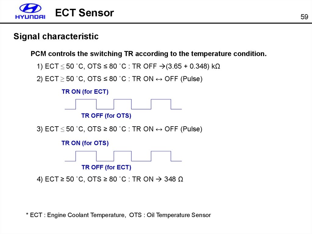
ECT SensorSignal characteristic
PCM controls the switching TR according to the temperature condition.
1) ECT ≤ 50 ˚C, OTS ≤ 80 ˚C : TR OFF (3.65 + 0.348) kΩ
2) ECT ≥ 50 ˚C, OTS ≤ 80 ˚C : TR ON ↔ OFF (Pulse)
TR ON (for ECT)
TR OFF (for OTS)
3) ECT ≤ 50 ˚C, OTS ≥ 80 ˚C : TR ON ↔ OFF (Pulse)
TR ON (for OTS)
TR OFF (for ECT)
4) ECT ≥ 50 ˚C, OTS ≥ 80 ˚C : TR ON 348 Ω
* ECT : Engine Coolant Temperature, OTS : Oil Temperature Sensor
59
56.
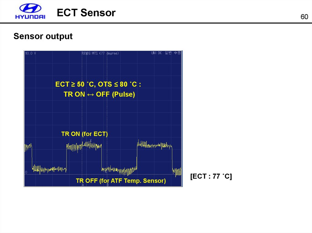
ECT Sensor60
Sensor output
ECT ≥ 50 ˚C, OTS ≤ 80 ˚C :
TR ON ↔ OFF (Pulse)
TR ON (for ECT)
TR OFF (for ATF Temp. Sensor)
[ECT : 77 ˚C]
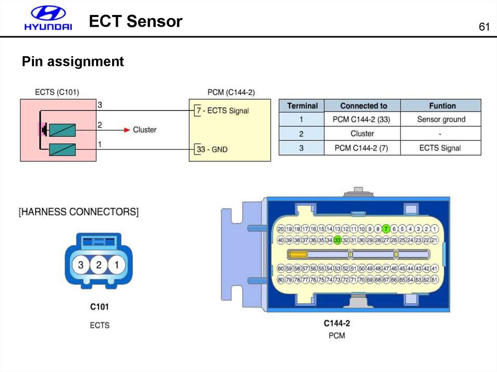
57.
ECT SensorPin assignment
61
58.
MAF Sensor62
MAF sensor outputs frequency (Hz) according to the intake
air amount.
Frequency generator is assembled in sensor and this
frequency is used for sensor output signal for better
controlling and preventing electrical noise interference.
IAT sensor is assembled with MAF sensor.
Technical Feature
• Measurable flow : ~ 250g/s
• Frequency : 0.7~12kHz
• Operating voltage : MAF : 9~16V
IAT : 5V
59.
MAF Sensor63
Output characteristics
Output Frequency
(KHz)
12
10
8
6
4
2
50
100
150
200
250
Intake air [g/s]
Sudden acceleration
Idle
60.
MAF SensorFailsafe
1. When MAP sensor is normal : replaced by MAP sensor
2. When MAP sensor is failed : replace by mapping data of intake air amount
according to throttle angle and Engine rpm
[[When MAF sensor connector is open]
64
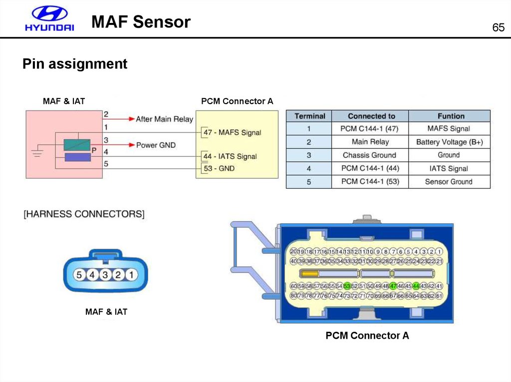
61.
MAF Sensor65
Pin assignment
MAF & IAT
PCM Connector A
MAF & IAT
PCM Connector A
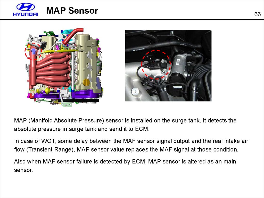
62.
MAP SensorMAP (Manifold Absolute Pressure) sensor is installed on the surge tank. It detects the
absolute pressure in surge tank and send it to ECM.
In case of WOT, some delay between the MAF sensor signal output and the real intake air
flow (Transient Range), MAP sensor value replaces the MAF signal at those condition.
Also when MAF sensor failure is detected by ECM, MAP sensor is altered as an main
sensor.
66
63.
MAP Sensor67
Technical features
Cover
Bush
• Sensor Type : Piezo Resistive
• Pressure range : 20 ~ 107 kPa
• Temperature range : -40℃ ~ 130℃
O-Ring
Housing Ass’y
• Supply voltage : 5 V ± 0.25 V
• Output voltage : 0.789 ~ 4.224V
NTC Thermistor
Sudden acceleration
4V
64.
MAP Sensor68
Pin assignment
PCM Connector B
MAP
MAP
PCM Connector B
65.
MAP SensorWhen ECM reaches a transient range such as sudden acceleration or deceleration, MAF
value is not reliable so MAP sensor signal is used instead of MAF’s.
Point A to B is kind of transient range example.
69
66.
MAP SensorFailsafe
[[When MAP sensor connector is open]
70
67.
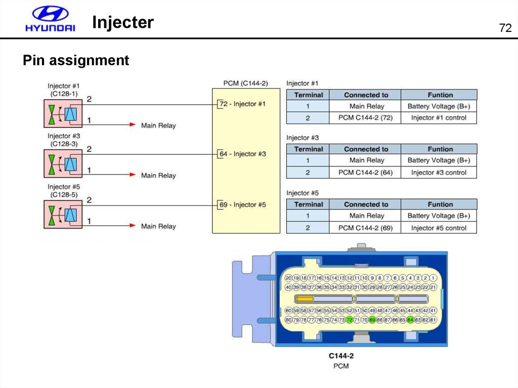
Injecter71
Technical features
10˚
• EV6 (Kefico) : 4 Hole, 2 Spray
20˚
• Flow rate: 150g/min
• Spray Pattern - Cone angle : 10˚
- Spray Angle : 20˚
• Coil resistance : 12 ~ 14.5 Ω
Engine speed limit
Engine speed limit by injection fuel cut is only available at driving range in case of AT.
RPM Limit at P or N is done by ETC throttle control.
68.
InjecterPin assignment
72
69.
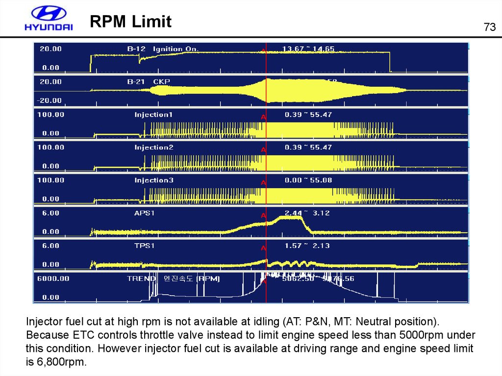
RPM LimitInjector fuel cut at high rpm is not available at idling (AT: P&N, MT: Neutral position).
Because ETC controls throttle valve instead to limit engine speed less than 5000rpm under
this condition. However injector fuel cut is available at driving range and engine speed limit
is 6,800rpm.
73
70.
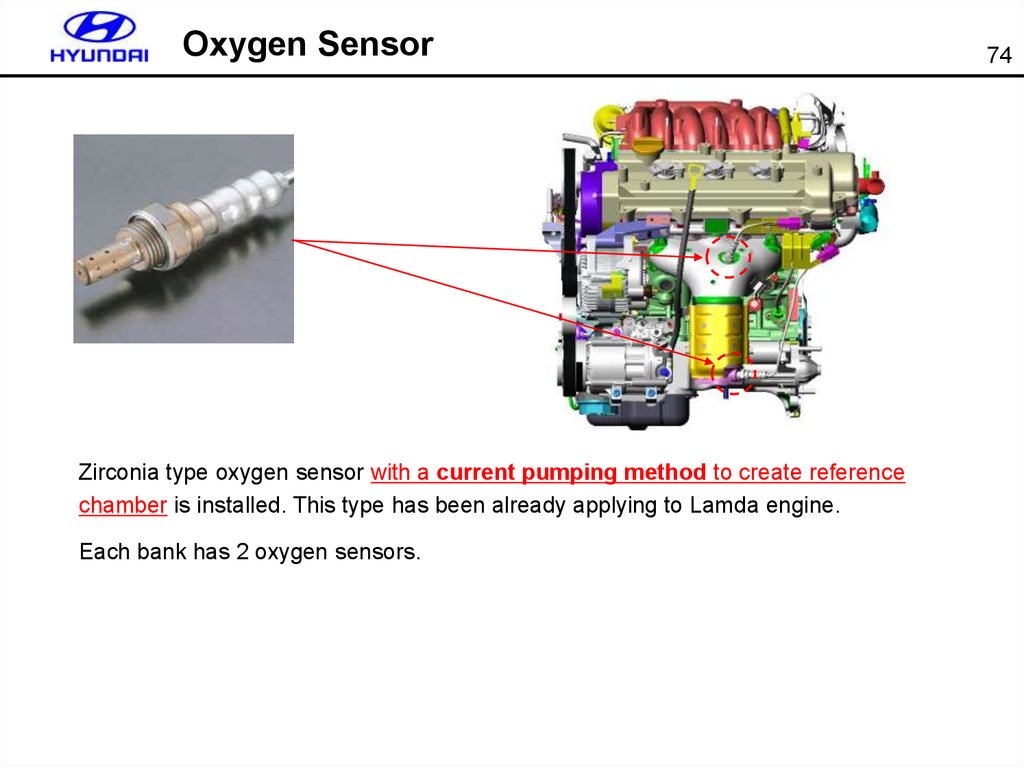
Oxygen SensorZirconia type oxygen sensor with a current pumping method to create reference
chamber is installed. This type has been already applying to Lamda engine.
Each bank has 2 oxygen sensors.
74
71.
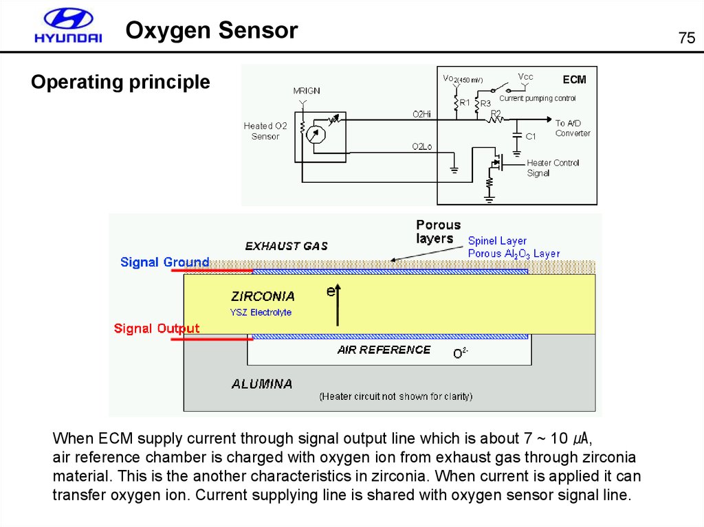
Oxygen SensorOperating principle
When ECM supply current through signal output line which is about 7 ~ 10 ㎂,
air reference chamber is charged with oxygen ion from exhaust gas through zirconia
material. This is the another characteristics in zirconia. When current is applied it can
transfer oxygen ion. Current supplying line is shared with oxygen sensor signal line.
75
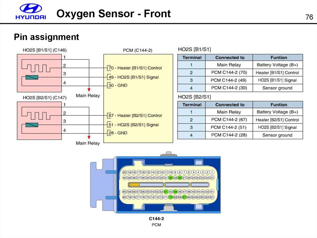
72.
Oxygen Sensor - FrontPin assignment
76
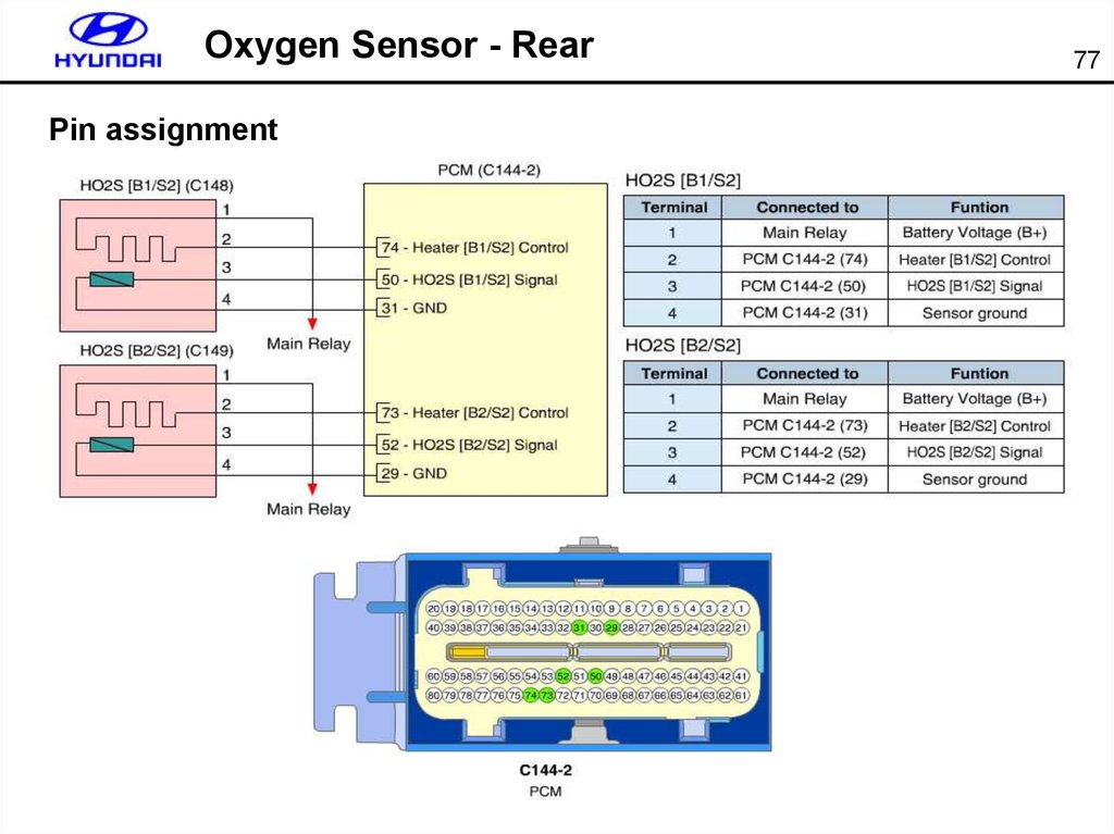
73.
Oxygen Sensor - RearPin assignment
77
74.
Oxygen Sensor78
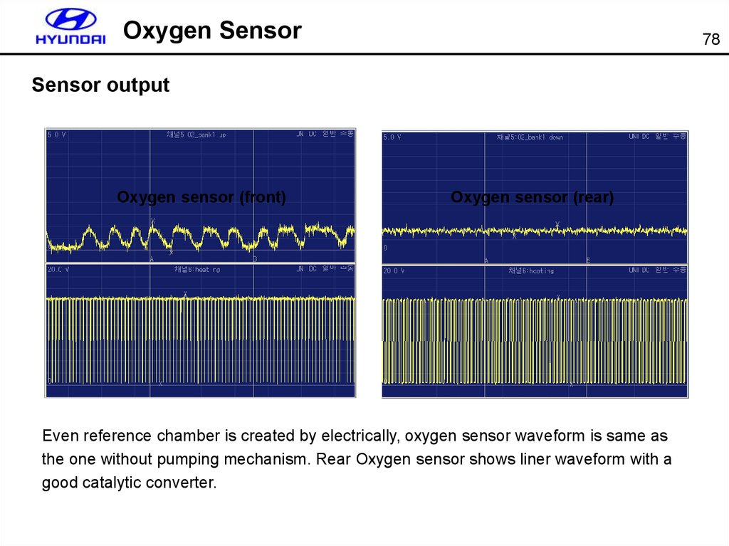
Sensor output
Oxygen sensor (front)
Oxygen sensor (rear)
Even reference chamber is created by electrically, oxygen sensor waveform is same as
the one without pumping mechanism. Rear Oxygen sensor shows liner waveform with a
good catalytic converter.
75.
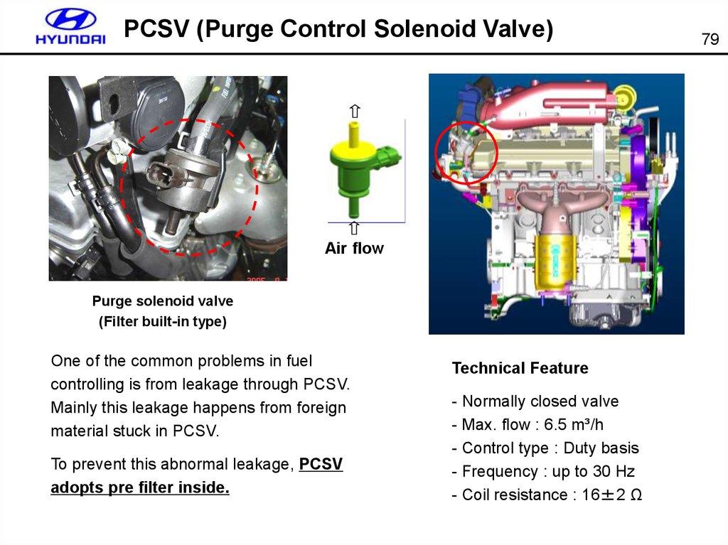
PCSV (Purge Control Solenoid Valve)Air flow
Purge solenoid valve
(Filter built-in type)
One of the common problems in fuel
controlling is from leakage through PCSV.
Mainly this leakage happens from foreign
material stuck in PCSV.
To prevent this abnormal leakage, PCSV
adopts pre filter inside.
Technical Feature
- Normally closed valve
- Max. flow : 6.5 m³/h
- Control type : Duty basis
- Frequency : up to 30 Hz
- Coil resistance : 16±2 Ω
79
76.
Knock SensorWhen knock is detected, ECM retards the ignition timing to certain range.
If knocking disappears after retarding ignition timing, ECM will advance the ignition timing
to improve engine power and torque.
80
77.
Knock Sensor81
Sensor output
1.6V
[Knock sensor output at engine idle]
78.
Knock SensorPin assignment
82
79.
Oil Temp. Sensor83
Technical feature
- Type : NTC thermistor
- Operating Temp. : -40℃ ~170℃
- Resistance : - 20℃ : 16.52㏀
20℃ : 2.45 ㏀
80℃ : 0.2889㏀
It is Installed on the cylinder block and detects the oil temperature for the fine OCV (Oil
Control Valve) control of CVVT system according to the temperature variation.
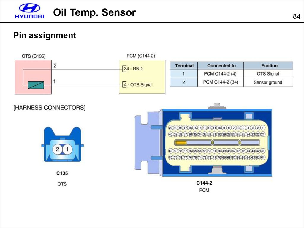
80.
Oil Temp. SensorPin assignment
84
81.
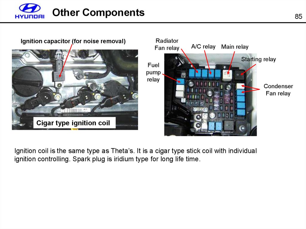
Other ComponentsIgnition capacitor (for noise removal)
85
Radiator
Fan relay
A/C relay Main relay
Starting relay
Fuel
pump
relay
Condenser
Fan relay
Cigar type ignition coil
Ignition coil is the same type as Theta’s. It is a cigar type stick coil with individual
ignition controlling. Spark plug is iridium type for long life time.