


 Механика
Похожие презентации:


Drivetrain System
1.
2.
After completing the module, the trainee will be able to …Explain drivetrain system components which are
applied to MQ4.
Explain major functions & principals of drivetrain
systems.
3.
DL3Transmission System
System
UM (19MY)
MQ4
Changes (in brief)
First model with wet DCT
SBW (dial)
Transmission
FWD 8-speed A/T
ICE model: FWD 6-speed Gen2
/ 8-speed AT,
FWD 8-speed wet DCT
HEV: FWD 6-speed AT Gen2
Steering
→
C-MDPS
R-MDPS (dual pinion type)
Reduced weight and increased
responsiveness
Suspension
(front/rear wheels)
→
MacPherson/multi-link
No ECS
Braking (ESC/EPB)
MEB-4 / cable-type
EPB (DIH)
(Hyundai Mobis)
MEB-5 / caliper-type EPB
(Hyundai Mobis)
※ HEV: IEB (Mando)
Improved braking force and
stability
Platform
Gen2 (N2)
Gen3 (N3): i-GMP
Improved design and
safety/driving performance
AWD
FF type (WIA Magna)
FF type (Hyundai WIA)
Terrain mode is available
4.
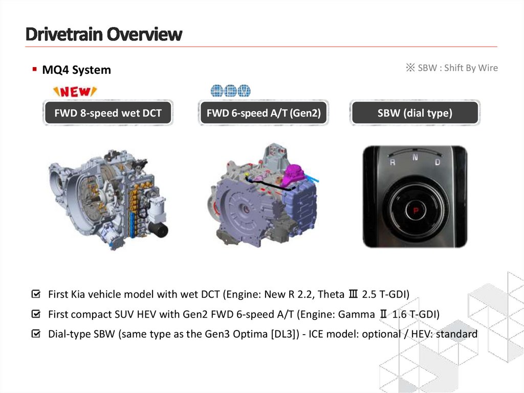
MQ4 SystemFWD 8-speed wet DCT
※ SBW : Shift By Wire
FWD 6-speed A/T (Gen2)
SBW (dial type)
First Kia vehicle model with wet DCT (Engine: New R 2.2, Theta Ⅲ 2.5 T-GDI)
First compact SUV HEV with Gen2 FWD 6-speed A/T (Engine: Gamma Ⅱ 1.6 T-GDI)
Dial-type SBW (same type as the Gen3 Optima [DL3]) - ICE model: optional / HEV: standard
5.
6.
L1. 8-Speed DCTCombination of advantages of A/T and dry DCT
Automated manual transmission
(dry DCT)
Double clutch, air-cooled, gear/clutch
actuator, Good fuel efficiency, noise,
clutch overheat, etc.
Automated manual transmission
(wet DCT)
Accumulator
Double clutch
system
Automatic transmission (A/T)
Valve body, oil-cooled, torque
converter, Clutch/brake, planetary
gear, multi-range, Easy gear shifting,
relatively low fuel efficiency
TCU and
valve
body
EOP
(Electric Oil Pump)
7.
L1. 8-Speed DCTDry-type DCT vs Wet-type DCT
Category
7-Speed dry-type DCT
FWD 8-speed wet-type DCT (MQ4)
Accumulator
Gear actuator
Main constituent
systems
Double clutch
(multi-plate wet
clutch + CSC)
Low-leak solenoid
Double clutch
(single-plate dry clutch)
Clutch actuator
HF EOP
HP EOP
<Valve body module>
Characteristics
Dual clutch
Single-plate dry clutch
Multi-plate wet clutch + CSC
Clutch control
Electric motor driven
Gear shifting
Mechanical actuator control
Valve body control
(HP EOP + accumulator + solenoid)
Gear lubrication
Lubrication through gear churning
Forced lubrication (Activation of HF EOP)
Clutch cooling
Air-cooled type
Oil-cooled type (Activation of HF EOP)
TCU
Separate or integrated type (Gen2)
Attached directly to the transmission
8.
L1. 8-Speed DCT※ GSC : Gear Shift Cylinder
Main components
SBW actuator
Solenoid valve
(Controls the clutch/gear)
Accumulator
Double clutch
(with CSC included)
GSC
TCU
HP EOP
HF EOP
Gear shift fork
9.
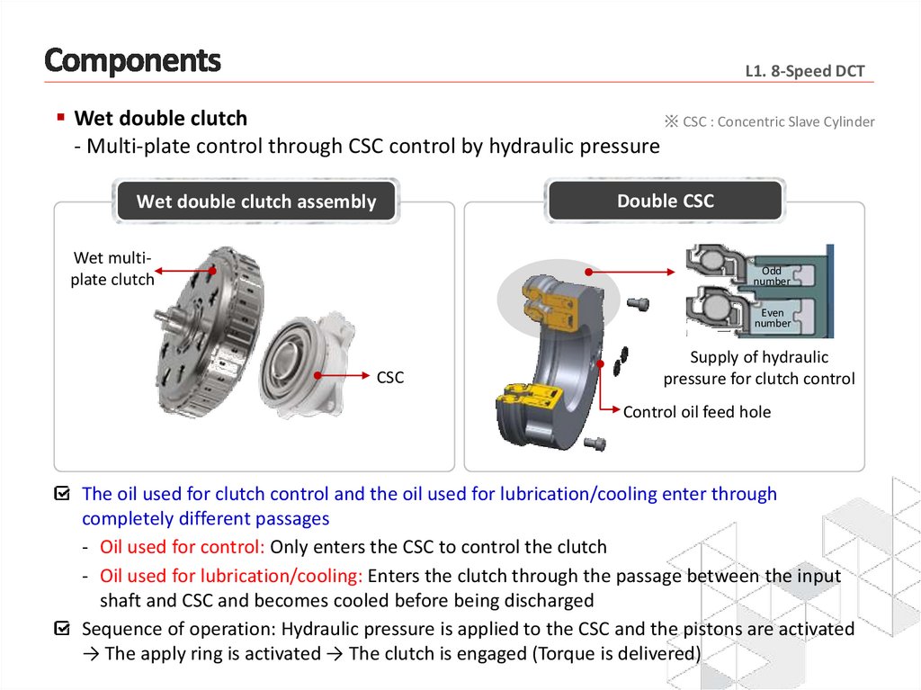
L1. 8-Speed DCTWet double clutch
※ CSC : Concentric Slave Cylinder
- Multi-plate control through CSC control by hydraulic pressure
Double CSC
Wet double clutch assembly
Wet multiplate clutch
Odd
number
Even
number
CSC
Supply of hydraulic
pressure for clutch control
Control oil feed hole
The oil used for clutch control and the oil used for lubrication/cooling enter through
completely different passages
- Oil used for control: Only enters the CSC to control the clutch
- Oil used for lubrication/cooling: Enters the clutch through the passage between the input
shaft and CSC and becomes cooled before being discharged
Sequence of operation: Hydraulic pressure is applied to the CSC and the pistons are activated
→ The apply ring is activated → The clutch is engaged (Torque is delivered)
10.
L1. 8-Speed DCTPrecautions when replacing the clutch assembly
- Removal/attachment by following the steps below
① Remove the snap ring and sealing cover
(Be careful to ensure that the housing is not damaged)
② Remove the clutch and CSC (using a dedicated jig)
Clutch
CSC
Snap ring
Sealing cover
(Use a magnetic jig)
①
Attach the jig ①
Remove the
(four holes)
bolts (at four points)
②
Turn the clutch ②
Attach the jig
counterclockwise 8 times to
and remove the CSC
remove it
* Tightening torque – 30 Nm±5
When replacing the double clutch pack, the CSC should also be replaced together.
(View the serial numbers engraved on the two devices to make sure they are a matching pair)
When handling (transporting/attaching/removing) the CSC, only hold the housing
- If you handle the CSC by holding the bearing, the piston may become removed
After replacement, perform manual learning by KDS and driving learning
- Air bleeding and touch point learning
11.
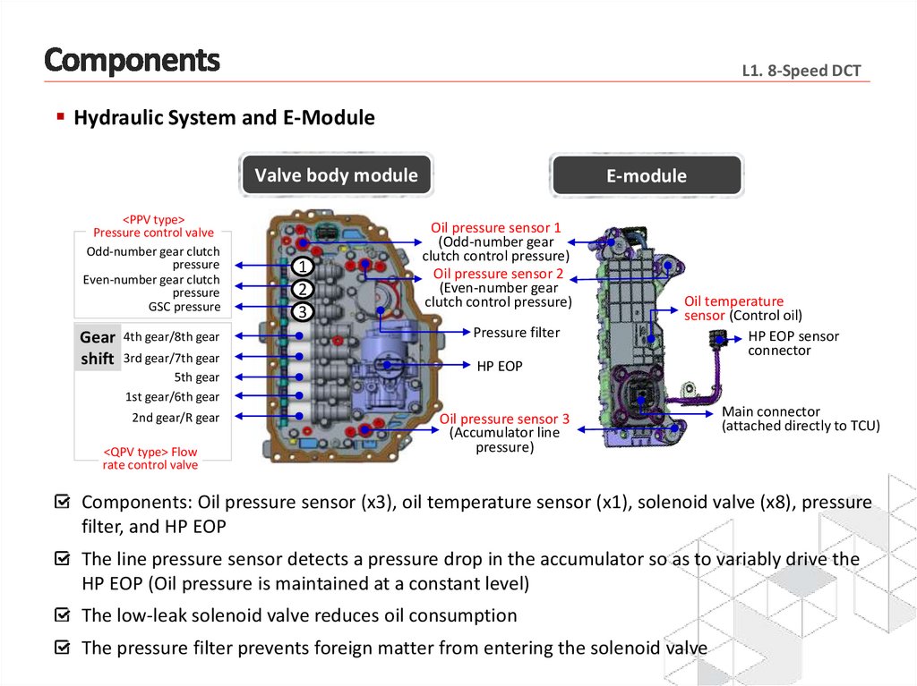
L1. 8-Speed DCTHydraulic System and E-Module
Valve body module
<PPV type>
Pressure control valve
Odd-number gear clutch
pressure
Even-number gear clutch
pressure
GSC pressure
Gear
shift
4th gear/8th gear
3rd gear/7th gear
5th gear
1st gear/6th gear
2nd gear/R gear
<QPV type> Flow
rate control valve
1
2
3
E-module
Oil pressure sensor 1
(Odd-number gear
clutch control pressure)
Oil pressure sensor 2
(Even-number gear
clutch control pressure)
Pressure filter
Oil temperature
sensor (Control oil)
HP EOP sensor
connector
HP EOP
Oil pressure sensor 3
(Accumulator line
pressure)
Main connector
(attached directly to TCU)
Components: Oil pressure sensor (x3), oil temperature sensor (x1), solenoid valve (x8), pressure
filter, and HP EOP
The line pressure sensor detects a pressure drop in the accumulator so as to variably drive the
HP EOP (Oil pressure is maintained at a constant level)
The low-leak solenoid valve reduces oil consumption
The pressure filter prevents foreign matter from entering the solenoid valve
12.
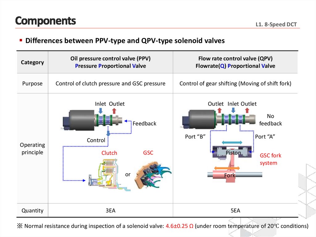
L1. 8-Speed DCTDifferences between PPV-type and QPV-type solenoid valves
Category
Oil pressure control valve (PPV)
Pressure Proportional Valve
Flow rate control valve (QPV)
Flowrate(Q) Proportional Valve
Purpose
Control of clutch pressure and GSC pressure
Control of gear shifting (Moving of shift fork)
Inlet Outlet
Outlet Inlet Outlet
No
feedback
Feedback
Operating
principle
Port “B”
Control
GSC
Clutch
or
Quantity
3EA
Port “A”
Piston
GSC fork
system
Fork
5EA
※ Normal resistance during inspection of a solenoid valve: 4.6±0.25 Ω (under room temperature of 20℃ conditions)
13.
L1. 8-Speed DCT※ GSC : Gear Shift Cylinder
GSC
3rd / 7th gear
5th gear
4th / 8th gear
Connector
Odd-number gear
input speed sensor
Main unit of GSC
(The flow path is
located on the rear)
Plate
Cylinder
housing
Piston
Even-number gear
input speed sensor
1st / 6th gear
Flexible PCB
2nd / R gear
Oil temperature
sensor (lubricant)
Gear shifting through control of (five) QPV-type solenoid valves
Position sensor for each cylinder (The piston position value can be checked from the current data)
Check that the piston is in the neutral position prior to assembly, and perform alignment when
required (See Fig. 2 below.)
- The piston automatically switches to the neutral position when the engine is turned off under
normal conditions
14.
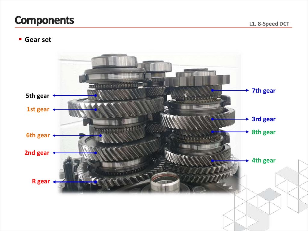
L1. 8-Speed DCTGear set
5th gear
7th gear
1st gear
3rd gear
6th gear
8th gear
2nd gear
4th gear
R gear
15.
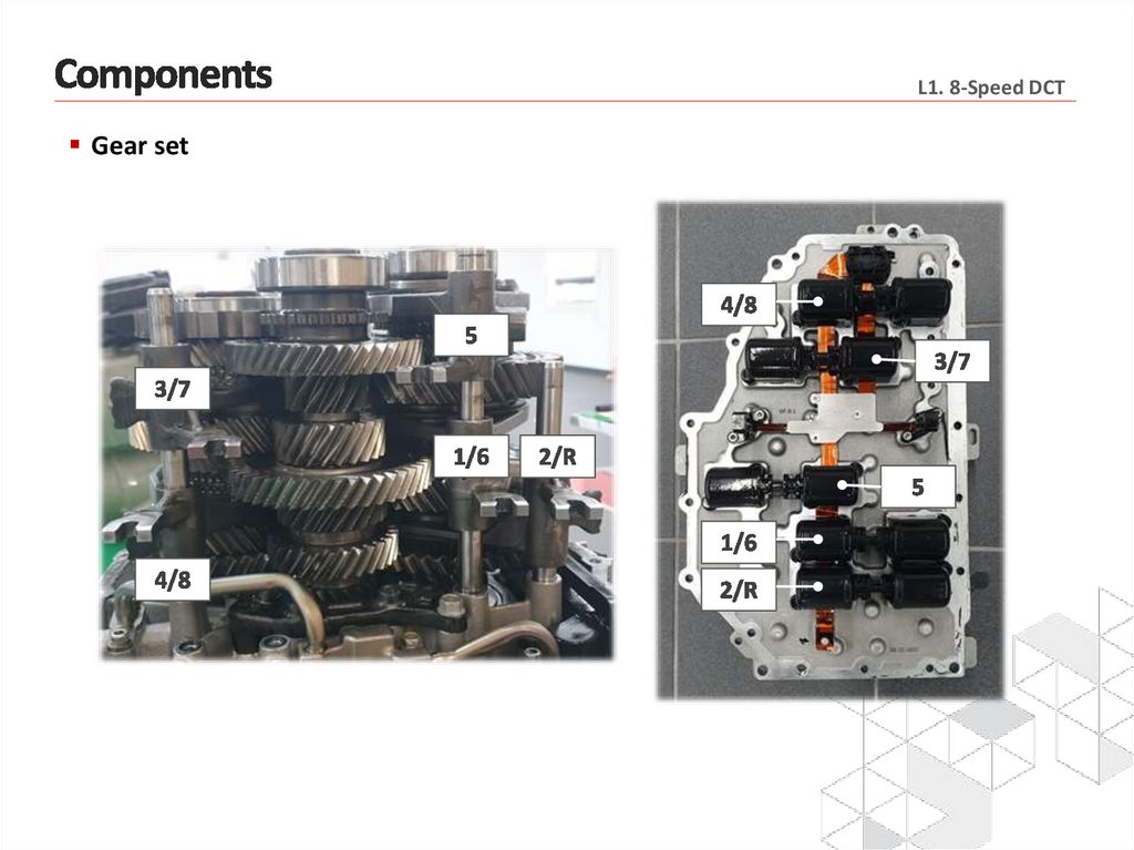
L1. 8-Speed DCTGear set
16.
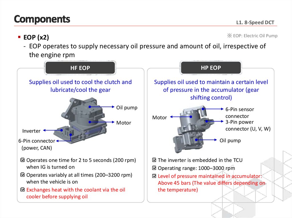
L1. 8-Speed DCT※ EOP: Electric Oil Pump
EOP (x2)
- EOP operates to supply necessary oil pressure and amount of oil, irrespective of
the engine rpm
HF EOP
HP EOP
Supplies oil used to cool the clutch and
lubricate/cool the gear
Supplies oil used to maintain a certain level
of pressure in the accumulator (gear
shifting control)
Oil pump
Motor
Inverter
6-Pin connector
(power, CAN)
Operates one time for 2 to 5 seconds (200 rpm)
when IG is turned on
Operates variably at all times (200–3200 rpm)
when the vehicle is on
Exchanges heat with the coolant via the oil
cooler before supplying oil
Motor
6-Pin sensor
connector
3-Pin power
connector (U, V, W)
Oil pump
The inverter is embedded in the TCU
Operating range: 1000–3000 rpm
Level of pressure maintained in accumulator:
Above 45 bars (The value differs depending on
the temperature)
17.
L1. 8-Speed DCTTransmission case
- Transmission components differ depending on the engine type and vehicle type
New R 2.2
Control oil
drain plug
Lubricant air Transmission
breather transfer ring
Accumulator
adapter
Oil cooler
Theta Ⅲ 2.5T
Accumulator
adapter
Oil cooler
Lubricant drain Lubricant Control oil
filler plug air breather
plug
Control oil
filler plug
Standard oil quantity (under room
temperature of 25℃ conditions)
- Lubricant / cooling oil (yellow): 3300–3400 cc
- Control oil (blue): 2450–2500 cc
18.
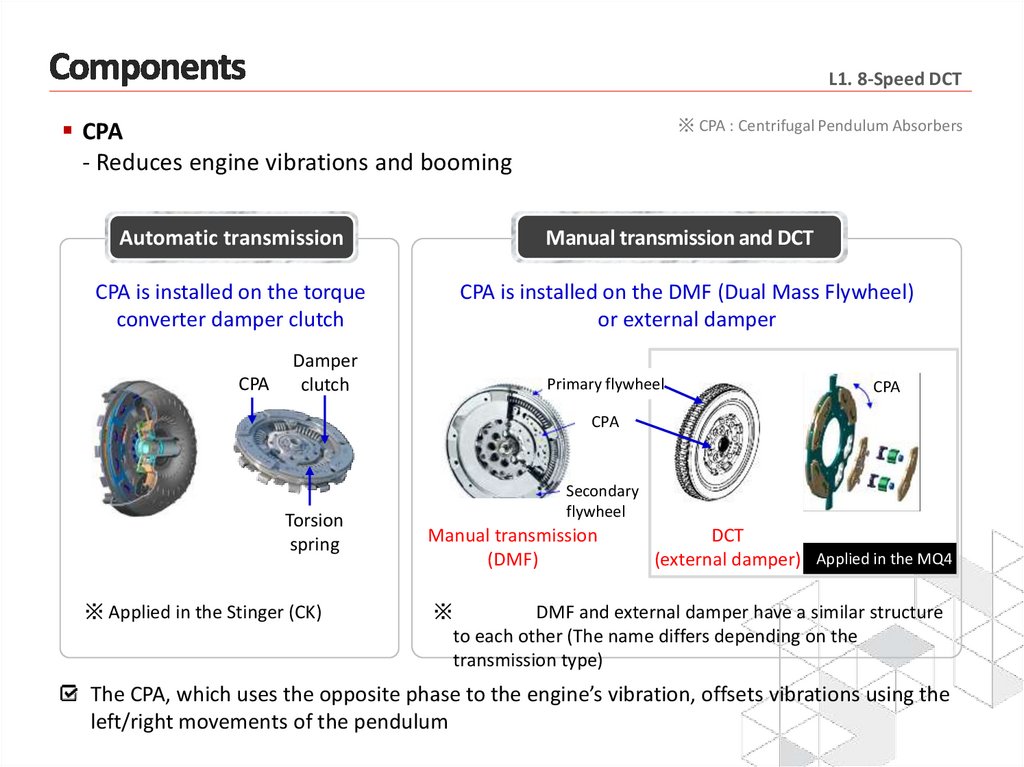
L1. 8-Speed DCTCPA
- Reduces engine vibrations and booming
Automatic transmission
CPA is installed on the torque
converter damper clutch
CPA
Damper
clutch
※ CPA : Centrifugal Pendulum Absorbers
Manual transmission and DCT
CPA is installed on the DMF (Dual Mass Flywheel)
or external damper
Primary flywheel
CPA
CPA
Torsion
spring
※ Applied in the Stinger (CK)
Secondary
flywheel
Manual transmission
(DMF)
DCT
(external damper) Applied in the MQ4
※
DMF and external damper have a similar structure
to each other (The name differs depending on the
transmission type)
The CPA, which uses the opposite phase to the engine’s vibration, offsets vibrations using the
left/right movements of the pendulum
19.
L1. 8-Speed DCT※ SMF : Single Mass Flywheel
CPA
- Classification depending on the installation location of the damper and CPA
(in manual transmissions)
SMF
+
damper clutch
Clutch
CPA
Pendulum
SMF
+
CPA clutch
DMF
+
rigid clutch
D/Shaft
Clutch
DMF
Clutch
D/Shaft
D/Shaft
Pendulum
CPA
CPA DMF
+
rigid clutch
DMF
Clutch
D/Shaft
20.
L1. 8-Speed DCTImages
left
right
21.
L1. 8-Speed DCTImages
Accumulator
HP EOP
Valve body
22.
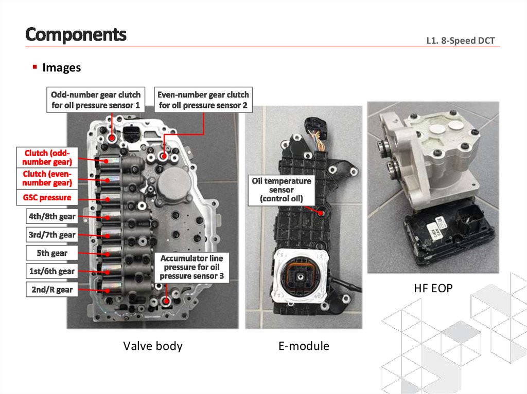
L1. 8-Speed DCTImages
HF EOP
Valve body
E-module
23.
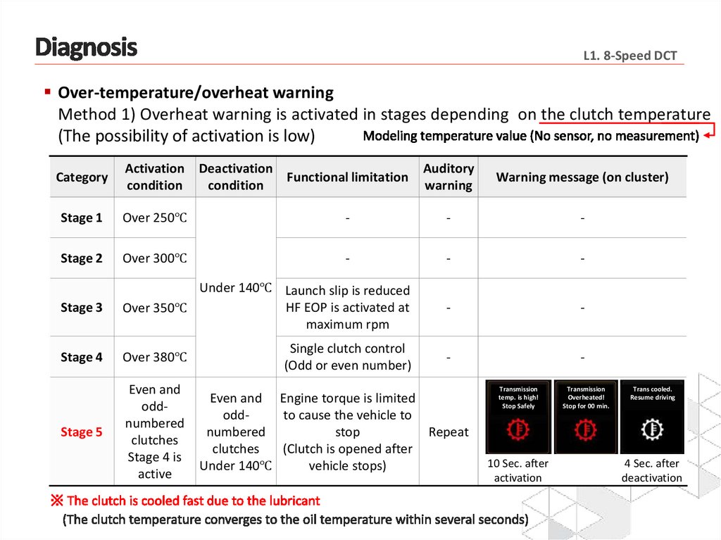
L1. 8-Speed DCTOver-temperature/overheat warning
Method 1) Overheat warning is activated in stages depending on the clutch temperature
(The possibility of activation is low)
Category
Activation
condition
Stage 1
Over 250℃
Stage 2
Over 300℃
Deactivation
Functional limitation
condition
Auditory
warning
Warning message (on cluster)
-
-
-
-
-
-
Stage 3
Under 140℃ Launch slip is reduced
HF EOP is activated at
Over 350℃
maximum rpm
-
-
Stage 4
Over 380℃
Single clutch control
(Odd or even number)
-
-
Stage 5
Even and
oddnumbered
clutches
Stage 4 is
active
Even and Engine torque is limited
oddto cause the vehicle to
numbered
stop
Repeat
clutches
(Clutch is opened after
vehicle stops)
Under 140℃
Transmission
temp. is high!
Stop Safely
10 Sec. after
activation
Transmission
Overheated!
Stop for 00 min.
Trans cooled.
Resume driving
4 Sec. after
deactivation
24.
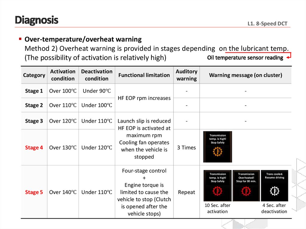
L1. 8-Speed DCTOver-temperature/overheat warning
Method 2) Overheat warning is provided in stages depending on the lubricant temp.
(The possibility of activation is relatively high)
Category
Stage 1
Activation Deactivation
Auditory
Functional limitation
condition
condition
warning
Over 100℃
Under 90℃
Warning message (on cluster)
-
-
HF EOP rpm increases
Stage 2
Over 110℃ Under 100℃
-
-
Stage 3
Over 120℃ Under 110℃ Launch slip is reduced
HF EOP is activated at
maximum rpm
Cooling fan operates
Over 130℃ Under 120℃ when the vehicle is
stopped
-
-
Stage 4
Stage 5
Four-stage control
+
Engine torque is
Over 140℃ Under 110℃ limited to cause the
vehicle to stop (Clutch
is opened after the
vehicle stops)
Transmission
temp. is high!
Stop Safely
3 Times
Transmission
temp. is high!
Stop Safely
Transmission
Overheated!
Stop for 00 min.
Trans cooled.
Resume driving
Repeat
10 Sec. after
activation
4 Sec. after
deactivation
25.
26.
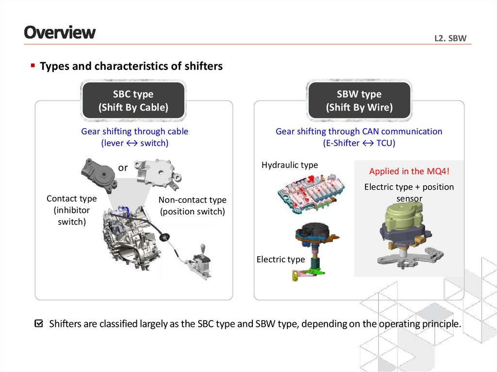
L2. SBWTypes and characteristics of shifters
SBC type
(Shift By Cable)
SBW type
(Shift By Wire)
Gear shifting through cable
(lever ↔ switch)
Gear shifting through CAN communication
(E-Shifter ↔ TCU)
Hydraulic type
or
Contact type
(inhibitor
switch)
Applied in the MQ4!
Electric type + position
sensor
Non-contact type
(position switch)
Electric type
Shifters are classified largely as the SBC type and SBW type, depending on the operating principle.
27.
L2. SBWImplementation of SBW system achieved without changing the structure of the
cable-type shifter
SBW-type electric actuator
(Controls shifting between P/R/N/D)
※ Position sensor data
Position of pos. sensor 1
Position of pos. sensor 2
Target gear range
Current gear range
Position sensor
(Judges the gear range)
Category
P
R
N
D
S1
83.7%
54.5%
37.6%
20.4%
S2
16.3%
45.5%
62.4%
79.6%
SBW actuator: Operates the three-phase motor and judges the gear range through the
internal sensors (relative value)
Position sensor: Judges the gear range based on the dual PWM signal values (absolute value)
(It performs the same functions as the SBC-type inhibitor switch)
The dial type is used (Same as the Gen3 Optima)
28.
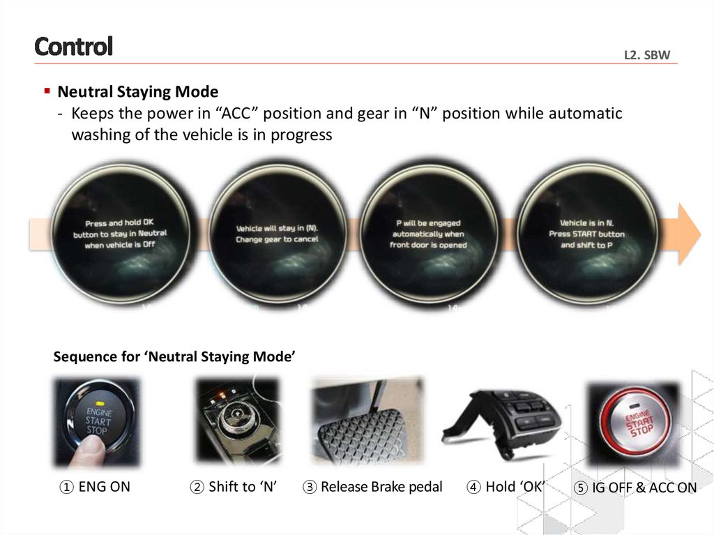
L2. SBWNeutral Staying Mode
- Keeps the power in “ACC” position and gear in “N” position while automatic
washing of the vehicle is in progress
Sequence for ‘Neutral Staying Mode’
① ENG ON
② Shift to ‘N’
③ Release Brake pedal
④ Hold ‘OK’
⑤ IG OFF & ACC ON
29.
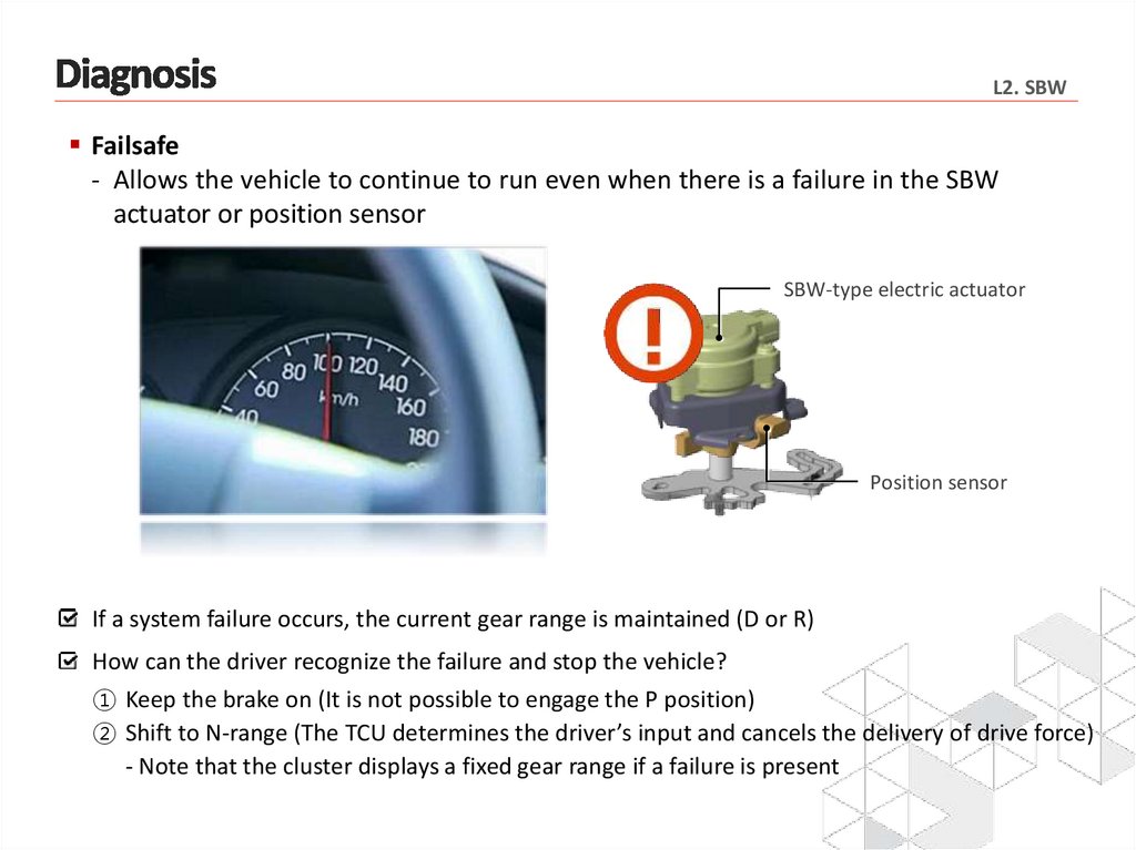
L2. SBWFailsafe
- Allows the vehicle to continue to run even when there is a failure in the SBW
actuator or position sensor
SBW-type electric actuator
Position sensor
If a system failure occurs, the current gear range is maintained (D or R)
How can the driver recognize the failure and stop the vehicle?
① Keep the brake on (It is not possible to engage the P position)
② Shift to N-range (The TCU determines the driver’s input and cancels the delivery of drive force)
- Note that the cluster displays a fixed gear range if a failure is present
30.
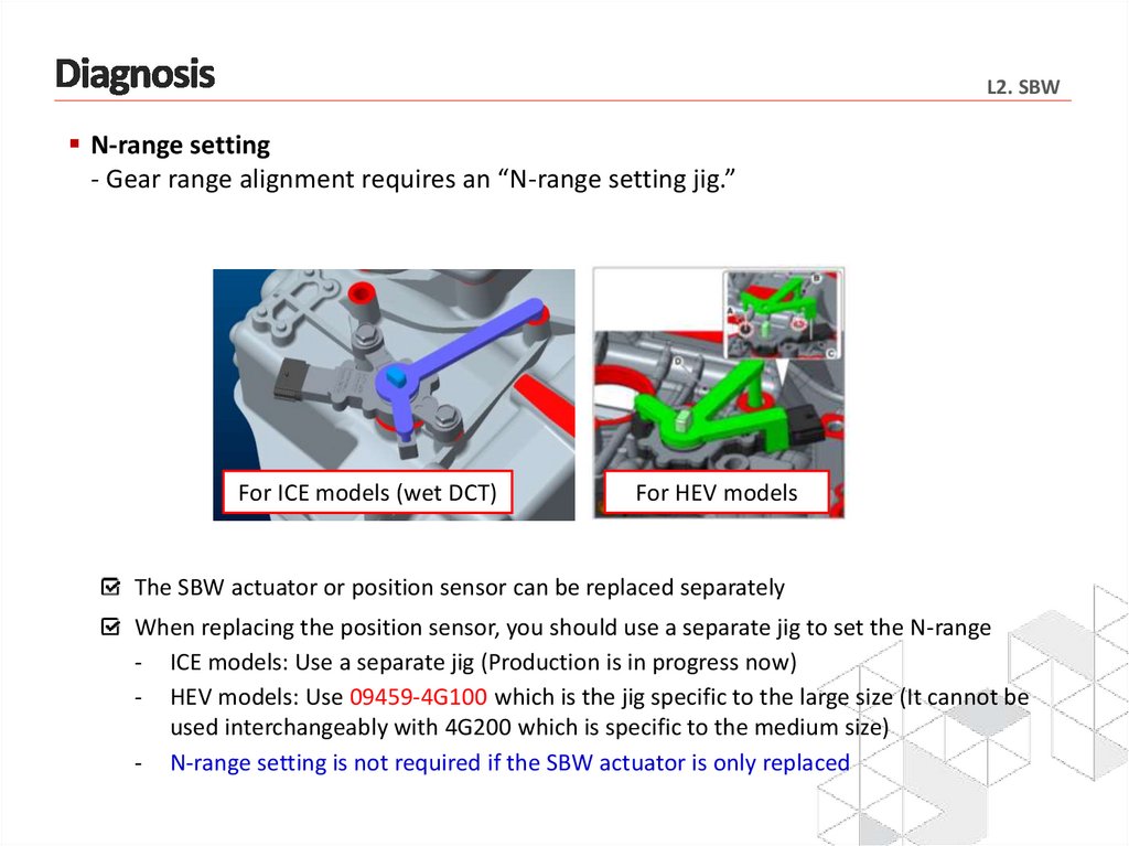
L2. SBWN-range setting
- Gear range alignment requires an “N-range setting jig.”
For ICE models (wet DCT)
For HEV models
The SBW actuator or position sensor can be replaced separately
When replacing the position sensor, you should use a separate jig to set the N-range
- ICE models: Use a separate jig (Production is in progress now)
- HEV models: Use 09459-4G100 which is the jig specific to the large size (It cannot be
used interchangeably with 4G200 which is specific to the medium size)
- N-range setting is not required if the SBW actuator is only replaced
31.
32.
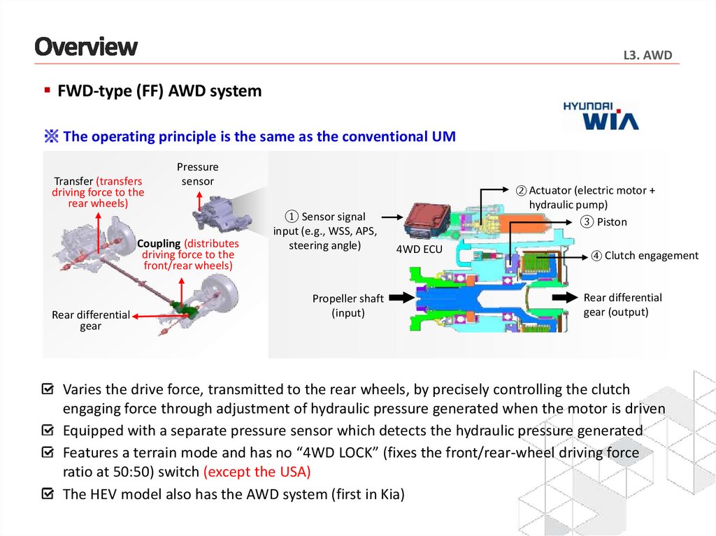
L3. AWDFWD-type (FF) AWD system
※ The operating principle is the same as the conventional UM
Transfer (transfers
driving force to the
rear wheels)
Pressure
sensor
Coupling (distributes
driving force to the
front/rear wheels)
Rear differential
gear
① Sensor signal
input (e.g., WSS, APS,
steering angle)
Propeller shaft
(input)
② Actuator (electric motor +
hydraulic pump)
③ Piston
4WD ECU
④ Clutch engagement
Rear differential
gear (output)
Varies the drive force, transmitted to the rear wheels, by precisely controlling the clutch
engaging force through adjustment of hydraulic pressure generated when the motor is driven
Equipped with a separate pressure sensor which detects the hydraulic pressure generated
Features a terrain mode and has no “4WD LOCK” (fixes the front/rear-wheel driving force
ratio at 50:50) switch (except the USA)
The HEV model also has the AWD system (first in Kia)
33.
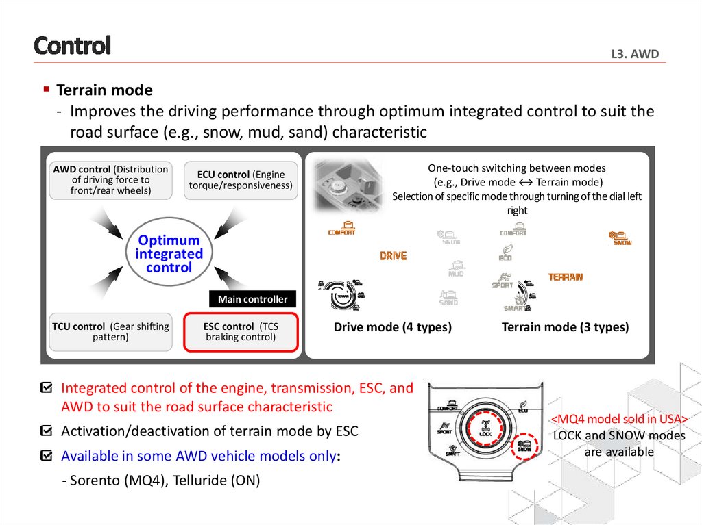
L3. AWDTerrain mode
- Improves the driving performance through optimum integrated control to suit the
road surface (e.g., snow, mud, sand) characteristic
AWD control (Distribution
of driving force to
front/rear wheels)
One-touch switching between modes
(e.g., Drive mode ↔ Terrain mode)
Selection of specific mode through turning of the dial left
right
ECU control (Engine
torque/responsiveness)
Optimum
integrated
control
Main controller
TCU control (Gear shifting
pattern)
ESC control (TCS
braking control)
Drive mode (4 types)
Integrated control of the engine, transmission, ESC, and
AWD to suit the road surface characteristic
Activation/deactivation of terrain mode by ESC
Available in some AWD vehicle models only:
- Sorento (MQ4), Telluride (ON)
Terrain mode (3 types)
<MQ4 model sold in USA>
LOCK and SNOW modes
are available