


 Механика
Похожие презентации:


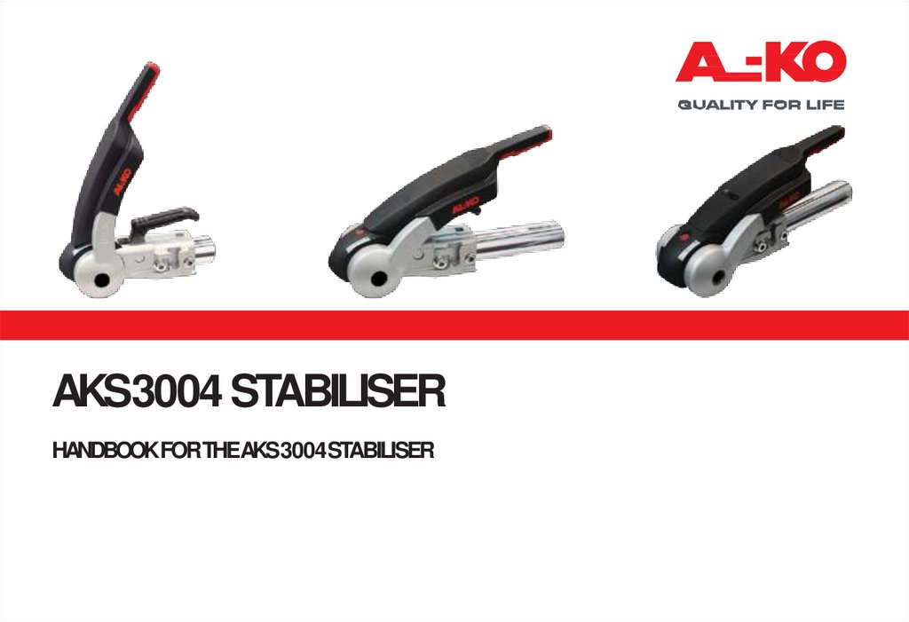
Aks3004 stabiliser
1.
AKS3004 STABILISERHANDBOOKFORTHEAKS3004STABILISER
2.
CONTENTS3
REGULATIONS
4
RESTRICTIONS OFUSE
5
SAFETY WARNINGS
6
FITMENT INSTRUCTIONS
8
FITMENT NOTES
10 OPERATING INSTRUCTIONS
14 SERVICING &CLEANING
19 FAQS
22 COMPLEMENTARYPRODUCTS
2
3.
REGULATIONS1. The AKS 3004 stabiliser must be used in conjunction
with 50mm dia. towballs which conform to ECDirective
94/20 (DIN 74058 or local equivalent).
2. Suitable for attachment to drawbars or approved
overrun braking equipment for single (and tandem axle)
caravan/trailers, with a minimum weight of 200kg and a
maximum permissible weight of 3000kg.
3. ECdesign approval has been given to the AL-KO AKS
3004 coupling under permit No. e1*94/20*0930*00.
3
4.
RESTRICTIONS OF USE1. The trailer coupling may only be connected to towing
vehicles where the clearances for the stabiliser can be
observed, in accordance with ECDirective 94/20 (DIN
74058). If these clearances are infringed by special
attachments, then the use must be checked separately.
The area above the towball of the vehicle must be free
from vehicle components or attachments (A) (e.g. spare
wheels, platforms etc.)
The clearance for the stabiliser lever must be at least
330mm (B) + the stroke movement (D) (85mm100mm), which equates to 440mm when used in
conjunction with an AL-KO overrun.
Max. 50mm (C) clearance between the centre of the
towball and top of the overrun assembly or fairing, to
ensure both coupling handle and stabiliser lever do not
foul on operation.
Maintain the same clearances for other
manufacturers’ overrun assemblies.
4
A
B
D
C
MIN. 60mm
MIN. 67mm
Fig 1 Necessary Clearances
2. May not be suitable for use with overrun devices which can
revolve above 25° (Fig 2) or BPW overruns fitted with gas strut
handbrakes from 2001 model year onwards. (If in any doubt
about usage consult your manufacturer).
3. Swan Neck towbars (fixed or detachable) are suitable for use with
the AKS3004 providing they comply to ECDirective 94/20 and
have the required minimum 60mm clearance, measured from the
centre of the towball (Fig2).
5.
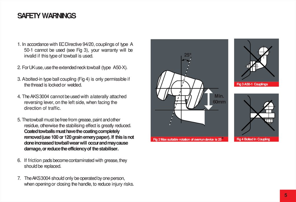
SAFETY WARNINGS1. In accordance with ECDirective 94/20, couplings of type A
50-1 cannot be used (see Fig 3), your warranty will be
invalid if this type of towball is used.
25°
2. For UK use, use the extended neck towball (type A50-X).
3. A bolted-in type ball coupling (Fig 4) is only permissible if
the thread is locked or welded.
4. The AKS 3004 cannot be used with a laterally attached
reversing lever, on the left side, when facing the
direction of traffic.
5. The towball must be free from grease, paint and other
residue, otherwise the stabilising effect is greatly reduced.
Coated towballs must have the coating completely
removed (use 100 or 120 grain emery paper). If this is not
done increased towball wear will occur and may cause
damage, or reduce the efficiency of the stabiliser.
Fig 3 A50-1 Couplings
Min.
60mm
Fig 2 Max suitable rotation of overrun device is 25°
Fig 4 Bolted In Coupling
6. If friction pads become contaminated with grease, they
should be replaced.
7. The AKS 3004 should only be operated by one person,
when opening or closing the handle, to reduce injury risks.
5
6.
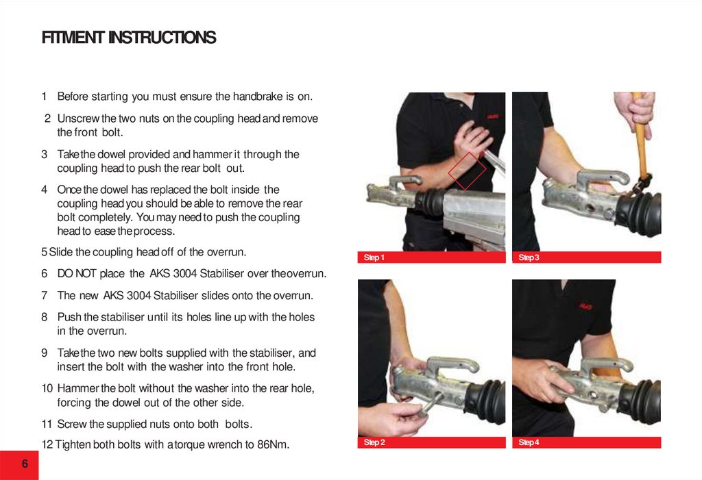
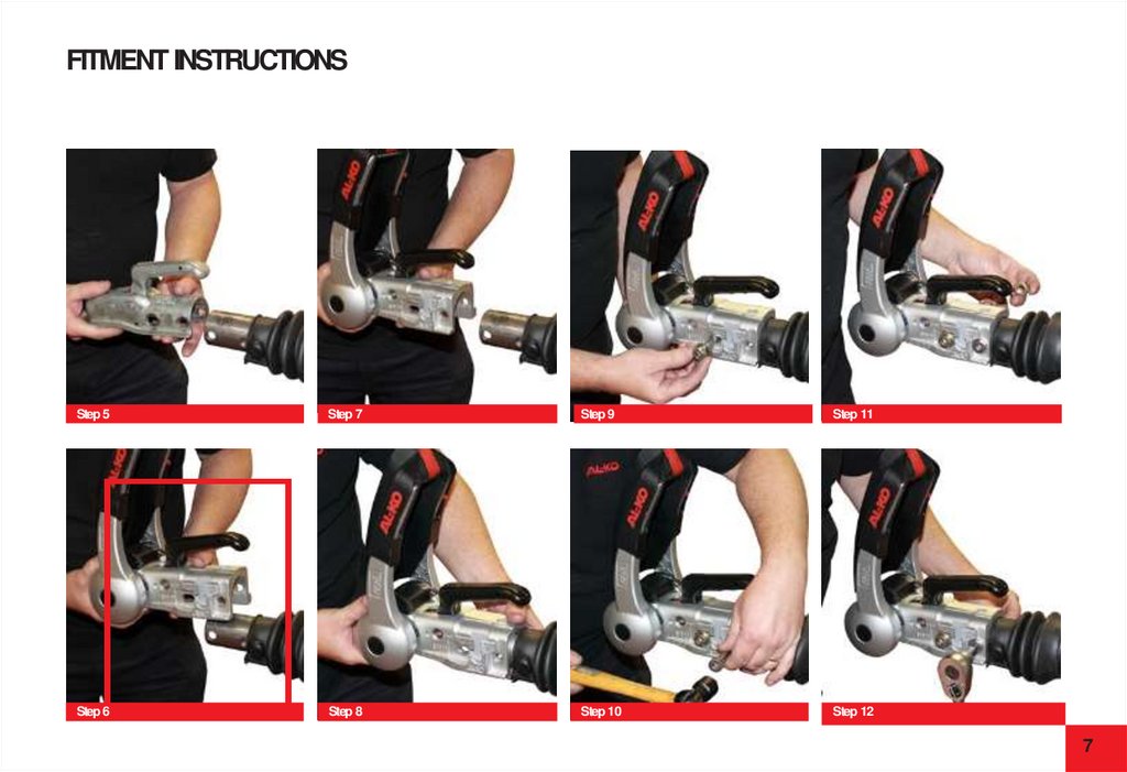
FITMENT INSTRUCTIONS1 Before starting you must ensure the handbrake is on.
2 Unscrew the two nuts on the coupling head and remove
the front bolt.
3 Take the dowel provided and hammer it through the
coupling head to push the rear bolt out.
4 Once the dowel has replaced the bolt inside the
coupling head you should be able to remove the rear
bolt completely. You may need to push the coupling
head to ease theprocess.
5 Slide the coupling head off of the overrun.
Step1
Step3
Step2
Step4
6 DO NOT place the AKS 3004 Stabiliser over theoverrun.
7 The new AKS 3004 Stabiliser slides onto the overrun.
8 Push the stabiliser until its holes line up with the holes
in the overrun.
9 Take the two new bolts supplied with the stabiliser, and
insert the bolt with the washer into the front hole.
10 Hammer the bolt without the washer into the rear hole,
forcing the dowel out of the other side.
11 Screw the supplied nuts onto both bolts.
12 Tighten both bolts with a torque wrench to 86Nm.
6
7.
FITMENT INSTRUCTIONSStep5
Step 7
Step 9
Step 11
Step6
Step 8
Step 10
Step 12
7
8.
FITMENT NOTES1 Always insert the bolts from the right hand side (when
facing caravan), to ensure the correct clearances are
allowed if fitting AL-KO Security Device (sold separately).
PLEASENOTETHATONMOST OVERRUN ASSEMBLIES, THE
DAMPER IS SECUREDBY THEREAR RETAINING BOLTAND
TELESCOPESOUTINDEPENDENTLY.
2 For non AL-KO overruns, with one horizontal and one
vertical fixing bolt, insert the front bolt through the
washer, overrun shaft and internal spacer (where used).
Finally, fit hexagonal self-locking nut and torque to
100Nm for 10,9 class bolts or 86Nm for 8,8 class bolts.
NOTE:The AKS 3004 is designed for 50mm draw shafts.
For smaller diameter shafts, spacers must be used.
These are provided with your stabiliser kit.
TakeMushroom Headed Coachbolt and insertfrom
top, fit original curved washer (from your overrun) and
hexagonal self-locking nut and torque to 86Nm (8,8 class
bolt supplied).
NOTE
The class of bolt will be stamped onto the bolt head.
8
Shaft Dia. Requirements
50mm
35mm
46mm
No spacers required
7.5mm spacer
2.0mm spacer - non AL-KO
9.
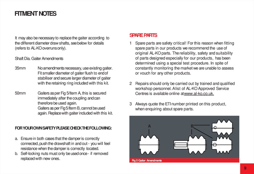
FITMENT NOTESIt may also be necessary to replace the gaiter according to
the different diameter draw shafts, see below for details
(refers to AL-KO overrunsonly).
Shaft Dia. Gaiter Amendments
35mm
50mm
No amendments necessary, use existing gaiter.
Fit smaller diameter of gaiter flush to end of
stabiliser and secure larger diameter of gaiter
with the retaining ring included with this kit.
Gaiters as per Fig 5/Item A, this is secured
immediately after the coupling and can
therefore be used again.
Gaiters as per Fig 5/Item B, cannot be used
again. Replace with gaiter included with this kit.
FORYOUROWNSAFETY PLEASE CHECKTHEFOLLOWING:
a. Ensure in both cases that the damper is correctly
connected, push the drawshaft in and out - you will feel
resistance when the damper is correctly located.
b. Self-locking nuts must only be used once - if removed
replaced with new ones.
SPAREPARTS
1 Spare parts are safety critical! For this reason when fitting
spare parts in our products we recommend the use of
original AL-KO parts. The reliability, safety and suitability
of parts designed especially for our products, has been
determined using a special test procedure. In spite of
constantly monitoring the market we are unable to assess
or vouch for any other products.
2 Repairs should only be carried out by trained and qualified
workshop personnel. A list of AL-KO Approved Service
Centres is available online atwww.al-ko.co.uk.
3 Always quote the ETI number printed on this product,
when enquiring about spare parts.
A
B
Fig 5 Gaiter Amendments
9
10.
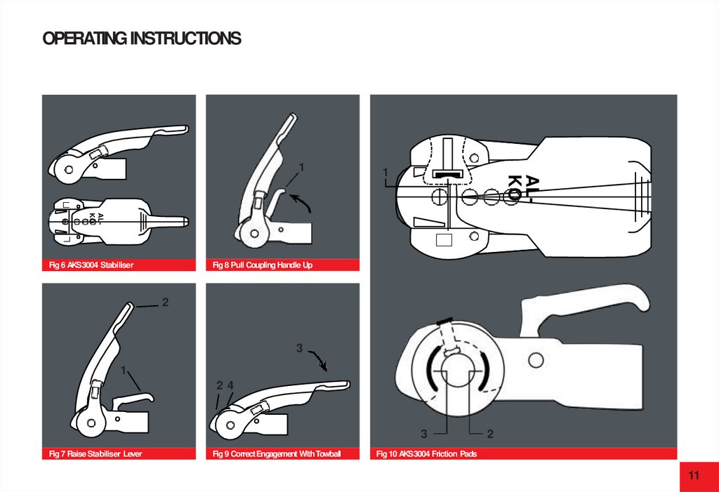
OPERATING INSTRUCTIONSAKS3004 SPECIFICATIONS
STABILISER UNIT
Coupling Handle (Fig 7/Item 1)
Stabiliser Lever (Fig 7/Item 2)
Tooperate the stabiliser (once coupled to the towball), simply
press the stabiliser lever down as far as it will go (Fig 9/Item3).
PREPARATIONFORCOUPLING/UNCOUPLING
Toensure the stabiliser is correctly coupled, check the arrowhead
lines up with the black line marked 2 (Fig 9 /Item 4 and Fig 13/C).
The Stabiliser lever (Fig 7/Item 2) must be in the
uppermost position (open).
COUPLING UP
Pull the coupling handle (Fig 8/Item 1) up in the direction of
arrow. The coupling mechanism has an open position, as
long as the AKS 3004 is not placed on the ball, the handle
will remain open. Put the opened coupling onto the clean
towball. The handle must now make an audible click and
return to the flat position.
WARNING
The coupling is correctly engaged when the green edge of
the safety indicator button is visible (Fig 9/Item 2).
10
UNCOUPLING
Pull the stabiliser lever up as far as it will go, open the coupling
handle and lift the AKS 3004 from the towball. With larger nose
loads, coupling and uncoupling can be made easier by using the
jockey wheel to assist lifting.
NOTE
The friction pads (Fig 10/Items 1, 2 & 3) are pressed against the
towball and hence generate a stabilising/damping force. These pads
are therefore subject to wear over time, however they will have a
long service life (circa.30,000 miles), provided they are well
maintained and kept free of grease/dirt.
11.
OPERATING INSTRUCTIONS1
ALKO
1
ALKO
Fig 8 Pull Coupling Handle Up
Fig 6 AKS3004 Stabiliser
2
3
1
24
3
Fig 7 Raise Stabiliser Lever
Fig 9 Correct Engagement WithTowball
2
Fig 10 AKS3004 Friction Pads
11
12.
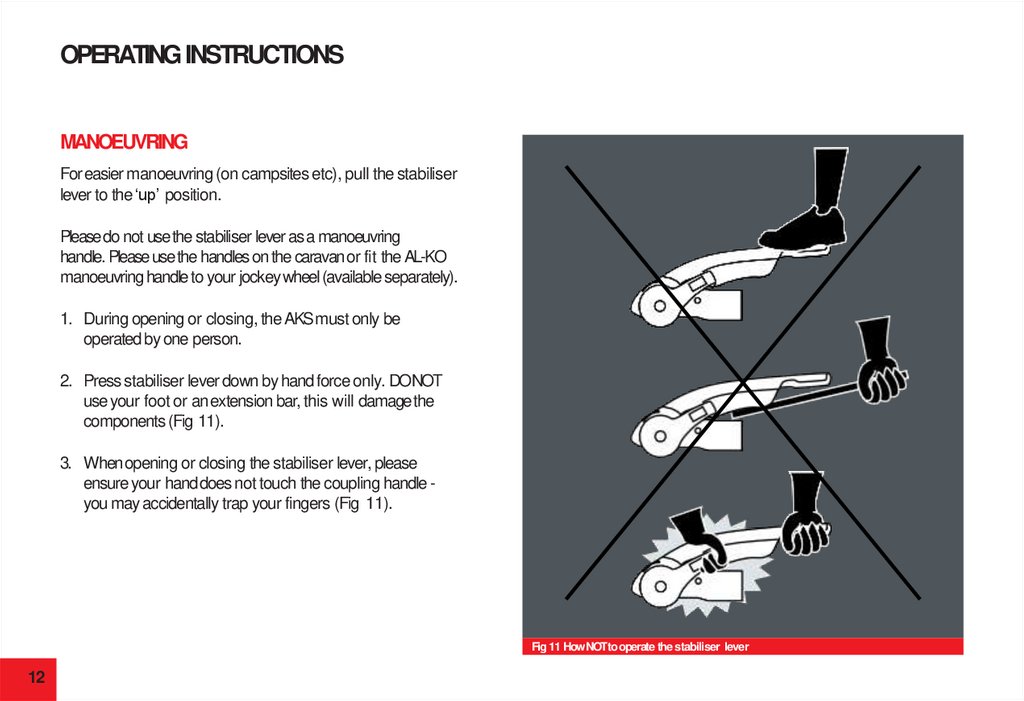
OPERATING INSTRUCTIONSMANOEUVRING
For easier manoeuvring (on campsites etc), pull the stabiliser
lever to the ‘up’ position.
Please do not use the stabiliser lever as a manoeuvring
handle. Please use the handles on the caravan or fit the AL-KO
manoeuvring handle to your jockey wheel (available separately).
1. During opening or closing, the AKS must only be
operated by one person.
2. Press stabiliser lever down by hand force only. DONOT
use your foot or an extension bar, this will damage the
components (Fig 11).
3. When opening or closing the stabiliser lever, please
ensure your hand does not touch the coupling handle you may accidentally trap your fingers (Fig 11).
Fig 11 How NOTto operate the stabiliser lever
12
13.
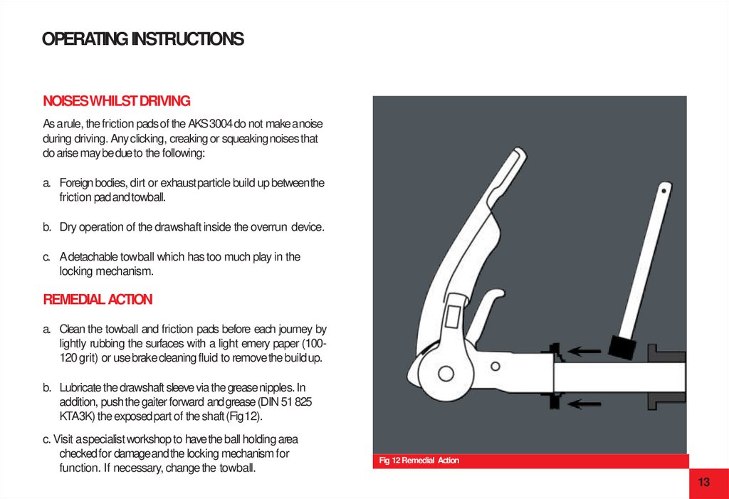
OPERATING INSTRUCTIONSNOISES WHILSTDRIVING
As a rule, the friction pads of the AKS3004 do not make a noise
during driving. Any clicking, creaking or squeaking noises that
do arise may be due to the following:
a. Foreign bodies, dirt or exhaust particle build up betweenthe
friction pad andtowball.
b. Dry operation of the drawshaft inside the overrun device.
c. A detachable towball which has too much play in the
locking mechanism.
REMEDIALACTION
a. Clean the towball and friction pads before each journey by
lightly rubbing the surfaces with a light emery paper (100120 grit) or usebrakecleaning fluid to removethe buildup.
b. Lubricate the drawshaft sleeve via the grease nipples. In
addition, push the gaiter forward and grease (DIN 51 825
KTA3K) the exposed part of the shaft (Fig12).
c. Visit a specialist workshop to have the ball holding area
checked for damage and the locking mechanism for
function. If necessary, change the towball.
Fig 12 Remedial Action
13
14.
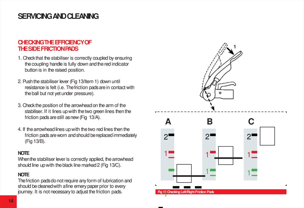
SERVICINGANDCLEANINGCHECKINGTHEEFFICIENCYOF
THESIDE FRICTIONPADS
1
1. Check that the stabiliser is correctly coupled by ensuring
the coupling handle is fully down and the red indicator
button is in the raised position.
2. Push the stabiliser lever (Fig 13/Item 1) down until
resistance is felt (i.e. The friction pads are in contact with
the ball but not yet under pressure).
3. Check the position of the arrowhead on the arm of the
stabiliser. If it lines up with the two green lines then the
friction pads are still as new (Fig 13/A).
4. If the arrowhead lines up with the two red lines then the
friction pads are worn and should be replaced immediately
(Fig 13/B).
NOTE
When the stabiliser lever is correctly applied, the arrowhead
should line up with the black line marked 2 (Fig 13/C).
NOTE
The friction pads do not require any form of lubrication and
should be cleaned with a fine emery paper prior to every
journey. It is not necessary to adjust the friction pads.
14
A
B
C
2
2
2
1
1
1
1
1
Fig 13 Checking Left/Right Friction Pads
1
15.
SERVICING ANDCLEANINGFRICTION PADREPLACEMENT(SIDE)
(Replace one at atime)
1. Uncouple the AKS 3004 stabiliser.
2. Remove protective caps (Fig 14/Item 1) with the aid of a
small screwdriver.
3. Press worn out pad inwards and remove (use punch and
hammer) (Fig 14/Item 2).
4. Insert new friction pad from below (after first re-inserting
shim washers if they were present) and press in as far as it
will go (Fig 14/Item 3 & Fig15).
2
3
1
Fig 14 Remove Worn Pads
Fig 15 Insert New Pads
15
16.
SERVICING ANDCLEANINGCHECKINGTHEEFFICIENCYOFTHE
FRONT/REAR FRICTIONPADS
FRICTION PADREPLACEMENT(FRONT/REAR)
1. Couple the AKS 3004 stabiliser to the towball but do not
activate the stabiliser.
2. Remove the soft dock (pull up & off), (Fig 20/Item 1).
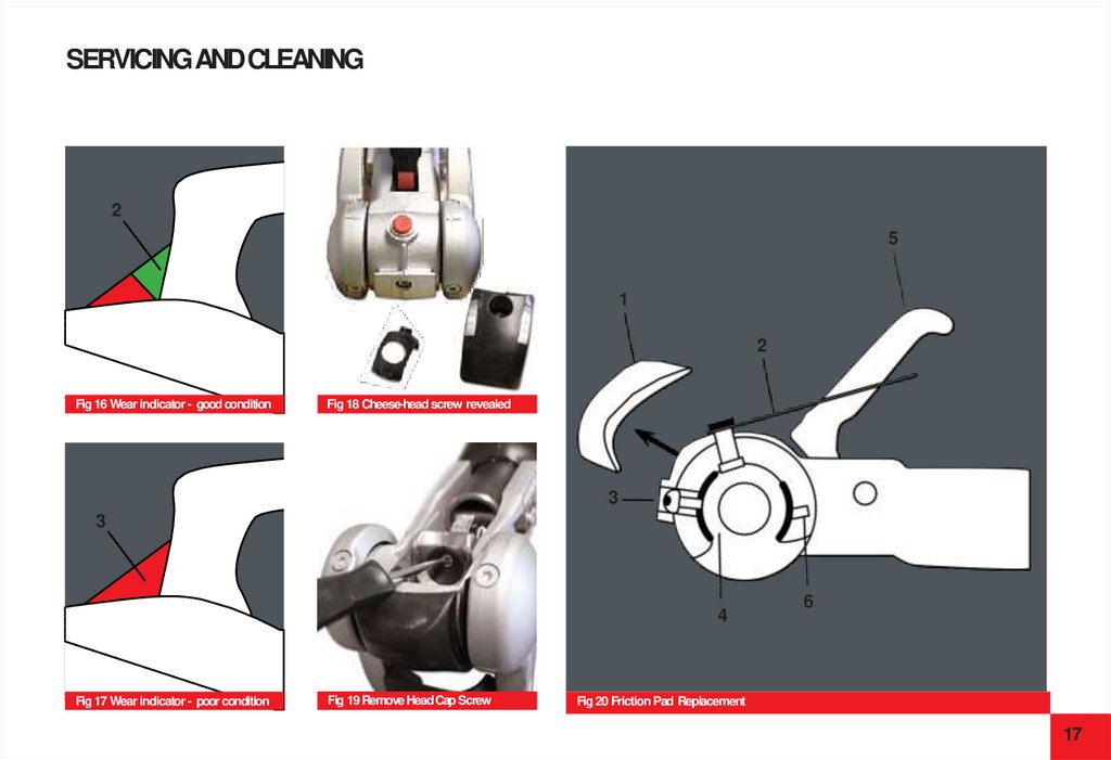
2. If a green indicator is visible (on the handle), then the
AKS 3004 is in a new condition or the pads and towball
are within the permissible limits (Fig 16/Item 2).
3. If only a red indicator is visible (Fig 17/Item 3), then this
may have the following causes:
a. AKS 3004 is okay but the towball has reached the
lowest limit of 49.61mm.
b. AKS 3004 stabiliser shows signs of wear.
c. Towball is in a new condition (50mm) but the front/
rear friction pads show a high degree of wear.
Establish the diameter of the towball so that
conclusions may be drawn as to the wear of the
friction pads (ball diameter must not be less than
49.61mm).
16
1. Uncouple the AKS 3004 stabiliser.
3. Press the safety indicator outwards and secure with SW14 hex.
spanner (not included), (Fig 20/ Item 2).
4. Remove cheese-head screw (Fig 20/Item 3 & Fig 18), using
special torx tool.
5. Press friction lining recess (Fig 20/Item 4) inwards and pull
down and out.
6. Open coupling handle (Fig 20/Item 5).
7. Remove countersunk head cap screw using special torx tool
(Fig 20/Item 6 & Fig 19).
8. Press friction pad inwards with a screwdriver and remove.
9. Fit new friction pads in reverse. Tighten screws to 5Nm (Fig 20/
Items 3&6)
10. Replace rubber soft dock, insert top section then bottom.
17.
SERVICING ANDCLEANING2
5
1
2
Fig 16 Wear indicator - good condition
Fig 18 Cheese-head screw revealed
3
3
4
Fig 17 Wear indicator - poor condition
Fig 19 Remove Head Cap Screw
6
Fig 20 Friction Pad Replacement
17
18.
SERVICING ANDCLEANINGIMPORTANT MAINTENANCE & CLEANINGADVICE
LUBRICATION
1. The towball should be cleaned regularly to remove grease
or other residue, to maintain the efficiency of the friction
pads. The use of thinners, white spirit or brake cleaner is
recommended for cleaning the towball and friction pads.
Should lubrication of the stabiliser parts become necessary,
then the following must be observed.
2. If friction pads are contaminated, they should not be
cleaned but replaced.
b. Areas may only be covered with a thin film of grease (Fig 21).
a. Clean all partsthoroughly.
c. Use multipurpose grease DIN 51825 KTA 3K.
3. The surface of the towball must be free of grooves, rust
or seizing marks.
4. Towballs coated with paint or similar, must have this
surface completely removed (use 100 or 120 grain
emery paper). If this is not done, increased towball wear
will occur and may cause damage to the AKS 3004
stabiliser components.
5. In winter, you should carefully spray only the visual
indicator with de-icer.
Fig 21 Lubrication points
18
WARNING
When lubricating,
ensure none gets into
the friction pad or
towball holding area.
19.
FAQSSTABILISER
FRICTION PADS
CANTHEREDAND/OR GREENINDICATOR
BUTTONSBEREPLACEDIFBROKEN/MISSING?
WHENSHOULDI CHANGEMY FRICTIONPADS?
This is usually caused by catching the button with the hitch
lock when fitting the hitch lock. The green section can in
some circumstances be replaced. Please contact AL-KO for
further advice.
The red part cannot be replaced.
THESTABILISERARMS KEEPLIFTING
UP WHENITRAVEL.
The most likely cause is the handbrake handle catching on
the stabiliser lever when braking.
Gently tease the handle away from the contact point - 5mm
should be sufficient. Whilst doing this, make sure you
support the base of the handbrake with a block of wood to
stop it coming off the ratchet plate.
The friction pad life expectancy is around 30,000 miles and can be
prolonged by regular cleaning with fine grade emery paper. Simply
remove them according to the instructions on pages 15-17, clean
them and replace.
However, they will wear out and this can be monitored via wear
indicators on your stabiliser. Seepages 14-17 for wear indicator
information, and instructions on changing them.
MY FRICTION PADSLOOK‘GLASSY’
WITH BITS FLAKING OFF.
Contamination has built up on the pads. This could be due to
grease on the towball, spray from the road, diesel fumes or failure
to remove all of the coating on the towball.
You need to remove the friction pads according to the instructions
on pages 15-17, and rub them lightly with a fine grade emery paper.
AL-KO recommend cleaning the pads in this way after every
journey to prevent build up and prolong friction pad life.
19
20.
FAQSWHENTOWINGI CANHEAR
LOUD CREAKINGORGROANING.
2 possible causes:
1
The incorrect towball could be fitted. Check your towball
is compatible with your stabiliser, and if it isn’t replace
it immediately. Failure to do so could result in your
caravan becoming unhitched during towing.
The necessary clearances are outlined on page 4, and
AL-KO recommends the AL-KO extended neck towball
which complies to all the necessary specifications.
2
Contamination may have built up on the friction pads.
This could be due to grease on the towball, spray from
the road, diesel fumes or failure to remove all of the
coating on the towball.
You need to remove the friction pads according to the
instructions on pages 15-17 and rub them lightly with a fine
grade emery paper.
AL-KO recommend cleaning the pads in this way after every
journey to prevent build up and prolong friction pad life.
20
THEENDHAS SNAPPEDOFFOFMY FRICTIONPAD.
This usually happens when the pads have not been fully
disengaged before dropping the stabiliser onto the towball. You
will need to replace the friction pad with a new one. Toavoid this
in future always place, rather than drop, the stabiliser onto the
towball and ensure the stabiliser lever has been lifted fully.
FRICTIONPADS?
Yes, but AL-KO do not recommend it. It is the hitch handle that
attaches the stabiliser to the towball. If you do not activate your
friction pads then you will haveno damping benefits.
TOWBALL
MY TOWBALLHAS GREASEONIT. CANI USEIT WITH
ANAKSSTABILISER?
Under no circumstances can a greased towball be used with an
AKS stabiliser. Ensure you remove all grease before hitching up.
Use a cloth to remove the excess grease, and use brake cleaner to
remove any residue. Wedo not recommend methylated spirit as
this can leave a greasy residue.
21.
FAQSI HAVEAN AKS 3004 STABILISER. WHATIS THE
MINIMUM CLEARANCETHATI NEEDBETWEEN
THETOWBALL AND TOWINGVEHICLE?
Minimum clearance is 68mm. This measurement is taken
from the centre of the towball to the nearest point of contact
with the towing vehicle.
I HAVEANEWAL-KO TOWBALL- DO
I NEEDTOTAKETHEPAINTOFF?
Yes. It is vital that all paint is removed from the towball before use,
as it will contaminate the stabiliser friction pads.
Toremove the paint, simply rub with emery paper, ideally finishing
with a coat of brake cleaner fluid to remove any residue.
Insufficient clearance will prevent the stabiliser from correct
articulation and could damage your car or even cause the
stabiliser to become detached from the towball.
WHICH TOWBALLS ARECOMPATIBLE
WITH THEAKS 3004STABILISER?
The necessary clearances are outlined on page 4, and
AL-KO recommends the AL-KO extended neck towball
which complies to all the necessary specifications.
The AL-KO extended neck towball is available to purchase
online at www.al-ko.co.uk.
21
22.
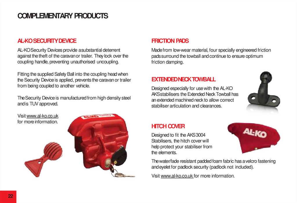
COMPLEMENTARY PRODUCTSAL-KO SECURITYDEVICE
FRICTION PADS
AL-KO Security Devices provide a substantial deterrent
against the theft of the caravan or trailer. They lock over the
coupling handle, preventing unauthorised uncoupling.
Made from low-wear material, four specially engineered friction
pads surround the towball and continue to ensure optimum
friction damping.
Fitting the supplied Safety Ball into the coupling head when
the Security Device is applied, prevents the caravan or trailer
from being coupled to another vehicle.
EXTENDEDNECKTOWBALL
The Security Device is manufactured from high density steel
and is TUV approved.
Visit www.al-ko.co.uk
for moreinformation.
Designed especially for use with the AL-KO
AKS stabilisers the Extended Neck Towball has
an extended machined neck to allow correct
stabiliser articulation and clearances.
HITCH COVER
Designed to fit the AKS 3004
Stabilisers, the hitch cover will
help protect your stabiliser from
the elements.
The water/fade resistant padded foam fabric has a velcro fastening
and eyelet for padlock security (padlock not included).
Visit www.al-ko.co.uk for more information.
22
23.
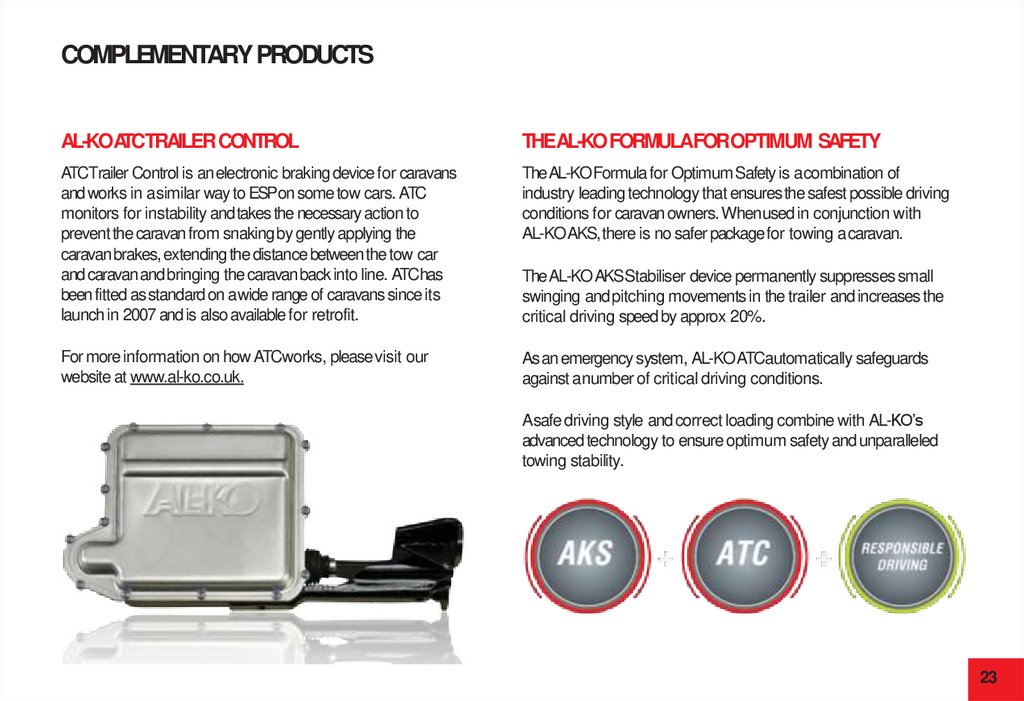
COMPLEMENTARY PRODUCTSAL-KOATCTRAILER CONTROL
THEAL-KO FORMULAFOROPTIMUM SAFETY
ATCTrailer Control is an electronic braking device for caravans
and works in a similar way to ESPon some tow cars. ATC
monitors for instability and takes the necessary action to
prevent the caravan from snaking by gently applying the
caravan brakes, extending the distance between the tow car
and caravan and bringing the caravan back into line. ATChas
been fitted as standard on a wide range of caravans since its
launch in 2007 and is also available for retrofit.
The AL-KO Formula for Optimum Safety is a combination of
industry leading technology that ensures the safest possible driving
conditions for caravan owners. When used in conjunction with
AL-KO AKS, there is no safer package for towing acaravan.
For more information on how ATCworks, please visit our
website at www.al-ko.co.uk.
As an emergency system, AL-KO ATCautomatically safeguards
against a number of critical driving conditions.
The AL-KO AKS Stabiliser device permanently suppresses small
swinging and pitching movements in the trailer and increases the
critical driving speed by approx 20%.
A safe driving style and correct loading combine with AL-KO’s
advanced technology to ensure optimum safety and unparalleled
towing stability.
23