


 Механика
Похожие презентации:


How to service the wear compensator of clutch actuator
1.
How to service the wear compensator of clutch actuator?Part to be replaced
Service procedure for
clutch system
Double
clutch (D/C)
Clutch
actuator (C/A)
Removing DCT → Replacing D/C + CES
Install the DCT after initializing the output rod length of
clutch actuator removed from DCT.
Reuse
Reuse
Replacement
Replacement
Removing DCT → Replacing D/C
Removing DCT → Replacing D/C +
CES + C/A
Install the DCT after initializing the output rod length of
new clutch actuator.
Replacement
Reuse
Reuse
Removing DCT → Replacing D/C + C/A
Replacement
Removing DCT → Replacing C/A + CES
Reuse
- Removing DCT → Replacing C/A
- Removing C/A only using an exclusive
jig → Replacing C/A
Replacement
Removing DCT → Replacing CES only
Replacement
Reuse
Necessity
of DCT
learning
Clutch
engagement
bearing &
fork system
(CES)
Replacement
Reuse
How to service the wear compensator
of clutch actuator?
Required
(G-SCAN)
Install the DCT after rewinding the new clutch actuator
(Rewinding aims to change the output rod length of
new clutch actuator to the output rod length of
clutch actuator removed from DCT).
- Reuse the existing clutch actuator.
- No adjustment of the output rod length of existing
clutch actuator is required.
2.
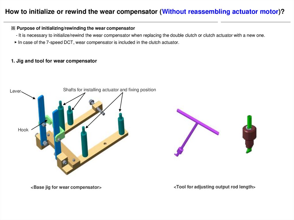
How to initialize or rewind the wear compensator (Without reassembling actuator motor)?※ Purpose of initializing/rewinding the wear compensator
- It is necessary to initialize/rewind the wear compensator when replacing the double clutch or clutch actuator with a new one.
▶ In case of the 7-speed DCT, wear compensator is included in the clutch actuator.
1. Jig and tool for wear compensator
Lever
Shafts for installing actuator and fixing position
Hook
<Base jig for wear compensator>
<Tool for adjusting output rod length>
3.
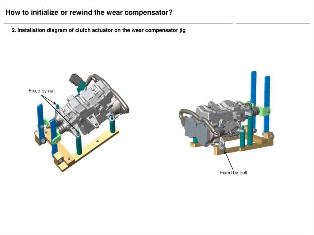
How to initialize or rewind the wear compensator?2. Installation diagram of clutch actuator on the wear compensator jig
Fixed by nut
Fixed by bolt
4.
Initializing method forwear compensator of clutch actuator
5.
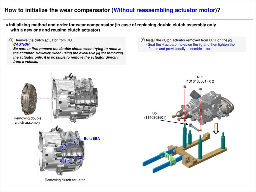
How to initialize the wear compensator (Without reassembling actuator motor)?▣ Initializing method and order for wear compensator (In case of replacing double clutch assembly only
with a new one and reusing clutch actuator)
① Remove the clutch actuator from DCT.
CAUTION
Be sure to first remove the double clutch when trying to remove
the actuator. However, when using the exclusive jig for removing
the actuator only, it is possible to remove the actuator directly
from a vehicle.
② Install the clutch actuator removed from DCT on the jig.
- Seat the 4 actuator holes on the jig and then tighten the
2 nuts and provisionally assemble 1 bolt.
Nut
(1310408001) X 2
Bolt
(1140308601)
Removing double
clutch assembly
Bolt: 6EA
Removing clutch actuator
6.
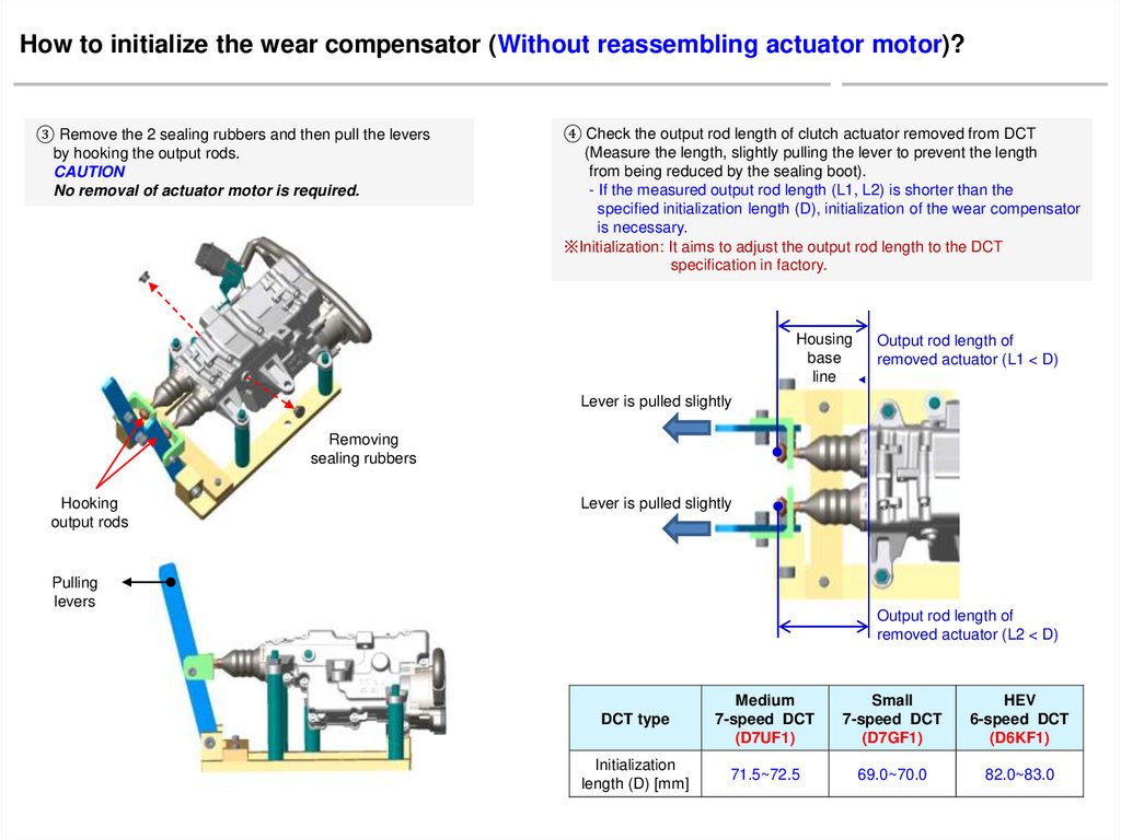
How to initialize the wear compensator (Without reassembling actuator motor)?④ Check the output rod length of clutch actuator removed from DCT
(Measure the length, slightly pulling the lever to prevent the length
from being reduced by the sealing boot).
- If the measured output rod length (L1, L2) is shorter than the
specified initialization length (D), initialization of the wear compensator
is necessary.
※Initialization: It aims to adjust the output rod length to the DCT
specification in factory.
Housing
base
line
Output rod length of
removed actuator (L1 < D)
▶
③ Remove the 2 sealing rubbers and then pull the levers
by hooking the output rods.
CAUTION
No removal of actuator motor is required.
Lever is pulled slightly
Removing
sealing rubbers
Hooking
output rods
Lever is pulled slightly
Pulling
levers
Output rod length of
removed actuator (L2 < D)
DCT type
Medium
7-speed DCT
(D7UF1)
Small
7-speed DCT
(D7GF1)
HEV
6-speed DCT
(D6KF1)
Initialization
length (D) [mm]
71.5~72.5
69.0~70.0
82.0~83.0
7.
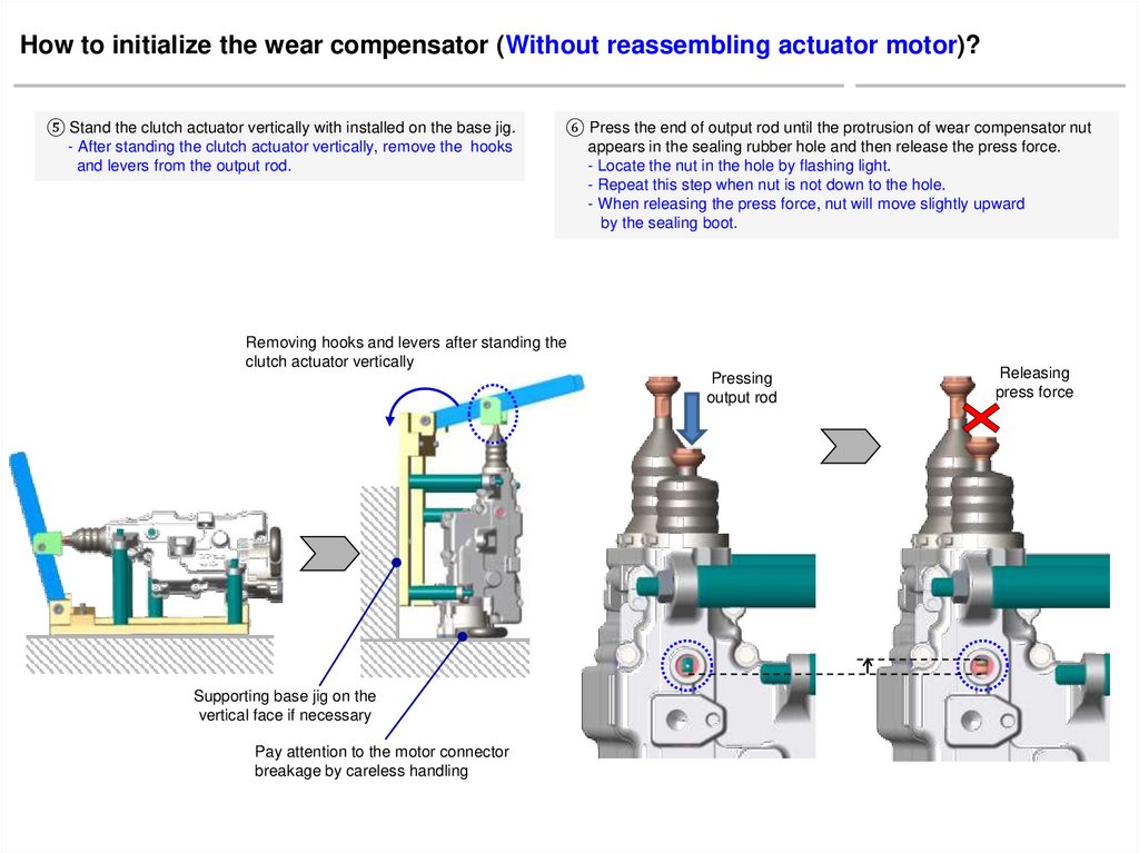
How to initialize the wear compensator (Without reassembling actuator motor)?⑤ Stand the clutch actuator vertically with installed on the base jig.
- After standing the clutch actuator vertically, remove the hooks
and levers from the output rod.
⑥ Press the end of output rod until the protrusion of wear compensator nut
appears in the sealing rubber hole and then release the press force.
- Locate the nut in the hole by flashing light.
- Repeat this step when nut is not down to the hole.
- When releasing the press force, nut will move slightly upward
by the sealing boot.
Removing hooks and levers after standing the
clutch actuator vertically
Pressing
output rod
Supporting base jig on the
vertical face if necessary
Pay attention to the motor connector
breakage by careless handling
Releasing
press force
8.
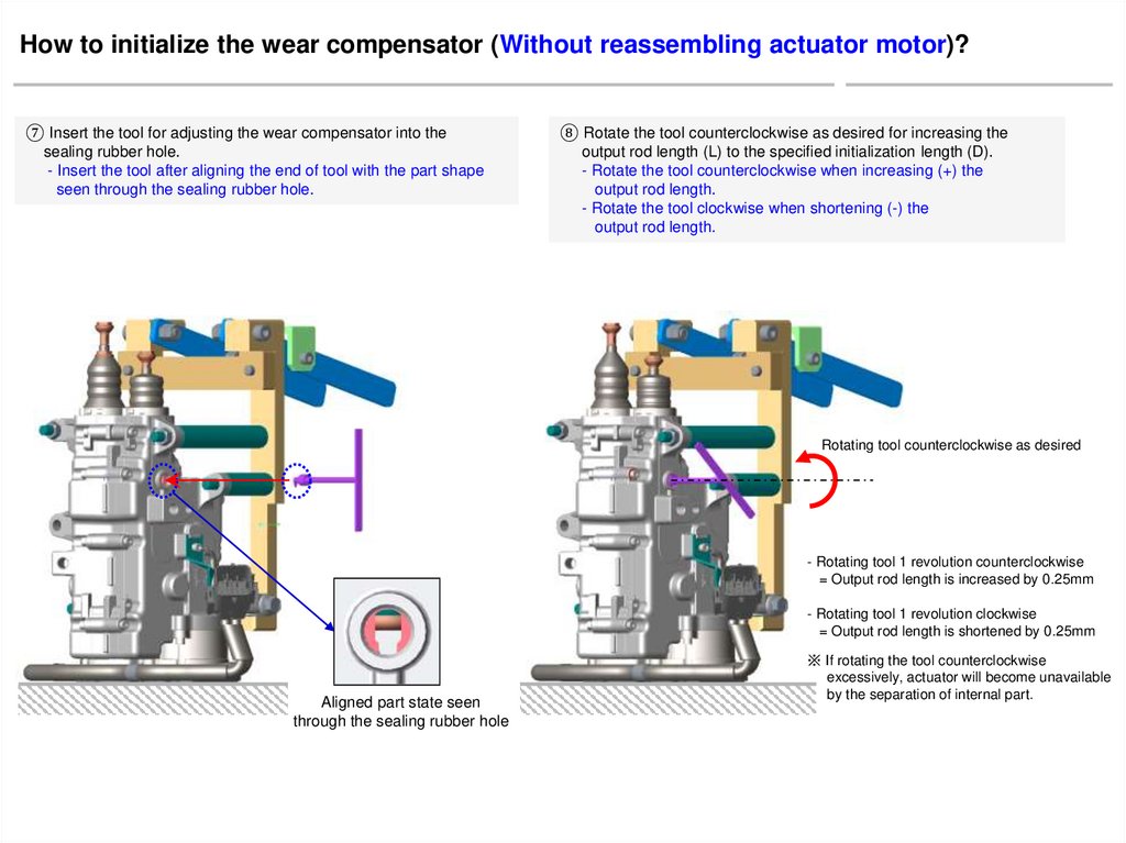
How to initialize the wear compensator (Without reassembling actuator motor)?⑦ Insert the tool for adjusting the wear compensator into the
sealing rubber hole.
- Insert the tool after aligning the end of tool with the part shape
seen through the sealing rubber hole.
⑧ Rotate the tool counterclockwise as desired for increasing the
output rod length (L) to the specified initialization length (D).
- Rotate the tool counterclockwise when increasing (+) the
output rod length.
- Rotate the tool clockwise when shortening (-) the
output rod length.
Rotating tool counterclockwise as desired
- Rotating tool 1 revolution counterclockwise
= Output rod length is increased by 0.25mm
- Rotating tool 1 revolution clockwise
= Output rod length is shortened by 0.25mm
Aligned part state seen
through the sealing rubber hole
※ If rotating the tool counterclockwise
excessively, actuator will become unavailable
by the separation of internal part.
9.
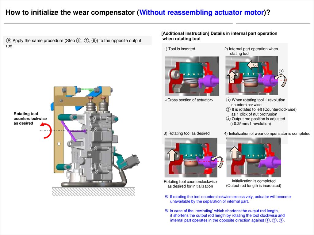
How to initialize the wear compensator (Without reassembling actuator motor)?⑨ Apply the same procedure (Step ⑥, ⑦, ⑧) to the opposite output
rod.
[Additional instruction] Details in internal part operation
when rotating tool
1) Tool is inserted
2) Internal part operation when
rotating tool
②
①
③
<Cross section of actuator>
Rotating tool
counterclockwise
as desired
3) Rotating tool as desired
Rotating tool counterclockwise
as desired for initialization
① When rotating tool 1 revolution
counterclockwise
② It is rotated to left (Counterclockwise)
as 1 click of nut protrusion
③ Output rod position is adjusted
(+0.25mm/1 revolution)
4) Initialization of wear compensator is completed
Initialization is completed
(Output rod length is increased)
※ If rotating the tool counterclockwise excessively, actuator will become
unavailable by the separation of internal part.
※ In case of the ‘rewinding’ which shortens the output rod length,
it shortens the output rod length by rotating the tool clockwise and
internal part operates in the opposite direction against ①, ②, ③.
10.
How to initialize the wear compensator (Without reassembling actuator motor)?⑪ Check the output rod length of actuator whose initialization is completed
(Measure the length, slightly pulling the lever so that the length is not
reduced by the sealing boot).
- Check that the measured output rod length (L1, L2) meets the
specified initialization length (D).
Removing tool
Lever is pulled slightly
Housing
base
line
▶
⑩ Remove the tool from the actuator. Hang the hooks
on the output rods and then lay the clutch actuator so that
base jig is contacted with the floor.
Output rod length after initialization
is completed (L1 = D)
Lever is pulled slightly
Pulling
lever
Output rod length after initialization
is completed (L2 = D)
DCT type
Medium
7-speed DCT
(D7UF1)
Small
7-speed DCT
(D7GF1)
HEV
6-speed DCT
(D6KF1)
Initialization
length (D) [mm]
71.5~72.5
69.0~70.0
82.0~83.0
11.
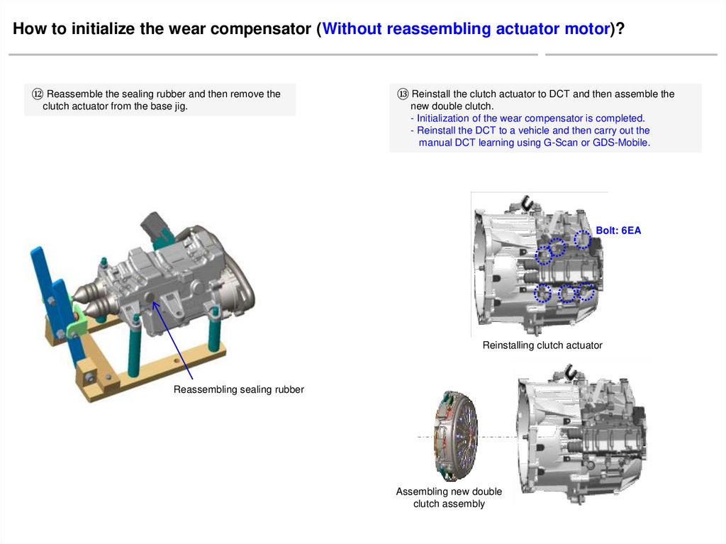
How to initialize the wear compensator (Without reassembling actuator motor)?⑫ Reassemble the sealing rubber and then remove the
clutch actuator from the base jig.
⑬ Reinstall the clutch actuator to DCT and then assemble the
new double clutch.
- Initialization of the wear compensator is completed.
- Reinstall the DCT to a vehicle and then carry out the
manual DCT learning using G-Scan or GDS-Mobile.
Bolt: 6EA
Reinstalling clutch actuator
Reassembling sealing rubber
Assembling new double
clutch assembly
12.
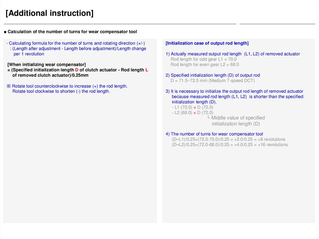
[Additional instruction]■ Calculation of the number of turns for wear compensator tool
- Calculating formula for the number of turns and rotating direction (+/-)
: (Length after adjustment - Length before adjustment)/Length change
per 1 revolution
[When initializing wear compensator]
= (Specified initialization length D of clutch actuator - Rod length L
of removed clutch actuator)/0.25mm
※ Rotate tool counterclockwise to increase (+) the rod length.
Rotate tool clockwise to shorten (-) the rod length.
[Initialization case of output rod length]
1) Actually measured output rod length (L1, L2) of removed actuator
Rod length for odd gear L1 = 70.0
Rod length for even gear L2 = 68.0
2) Specified initialization length (D) of output rod
D = 71.5~72.5 mm (Medium 7-speed DCT)
3) It is necessary to initialize the output rod length of removed actuator
because measured rod length (L1, L2) is shorter than the specified
initialization length (D).
- L1 (70.0) < D (72.0)
- L2 (68.0) < D (72.0)
└ Middle value of specified
initialization length (D)
4) The number of turns for wear compensator tool
(D–L1)/0.25=(72.0-70.0)/0.25 = +2.0/0.25 = +8 revolutions
(D–L2)/0.25=(72.0-68.0)/0.25 = +4.0/0.25 = +16 revolutions
13.
Rewinding method forwear compensator of clutch actuator
14.
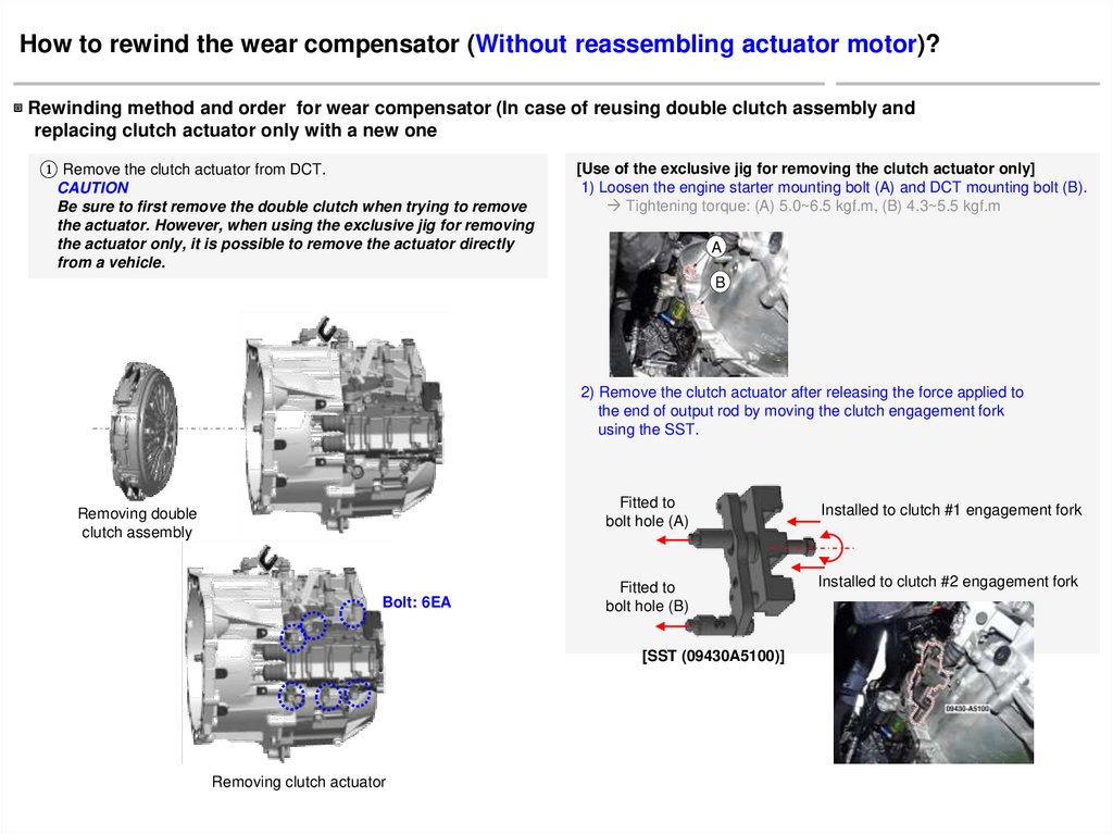
How to rewind the wear compensator (Without reassembling actuator motor)?▣ Rewinding method and order for wear compensator (In case of reusing double clutch assembly and
replacing clutch actuator only with a new one
① Remove the clutch actuator from DCT.
CAUTION
Be sure to first remove the double clutch when trying to remove
the actuator. However, when using the exclusive jig for removing
the actuator only, it is possible to remove the actuator directly
from a vehicle.
[Use of the exclusive jig for removing the clutch actuator only]
1) Loosen the engine starter mounting bolt (A) and DCT mounting bolt (B).
Tightening torque: (A) 5.0~6.5 kgf.m, (B) 4.3~5.5 kgf.m
A
B
2) Remove the clutch actuator after releasing the force applied to
the end of output rod by moving the clutch engagement fork
using the SST.
Removing double
clutch assembly
Bolt: 6EA
Fitted to
bolt hole (A)
Installed to clutch #1 engagement fork
Fitted to
bolt hole (B)
Installed to clutch #2 engagement fork
[SST (09430A5100)]
Removing clutch actuator
15.
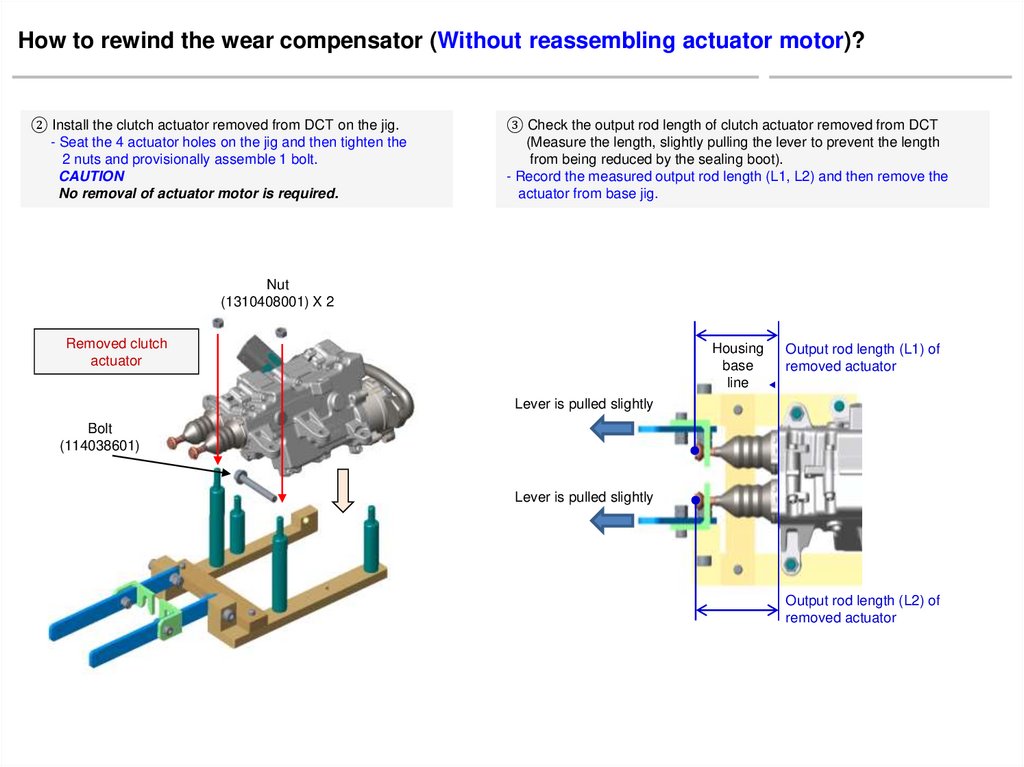
How to rewind the wear compensator (Without reassembling actuator motor)?② Install the clutch actuator removed from DCT on the jig.
- Seat the 4 actuator holes on the jig and then tighten the
2 nuts and provisionally assemble 1 bolt.
CAUTION
No removal of actuator motor is required.
③ Check the output rod length of clutch actuator removed from DCT
(Measure the length, slightly pulling the lever to prevent the length
from being reduced by the sealing boot).
- Record the measured output rod length (L1, L2) and then remove the
actuator from base jig.
Nut
(1310408001) X 2
Housing
base
line
Output rod length (L1) of
removed actuator
▶
Removed clutch
actuator
Lever is pulled slightly
Bolt
(114038601)
Lever is pulled slightly
Output rod length (L2) of
removed actuator
16.
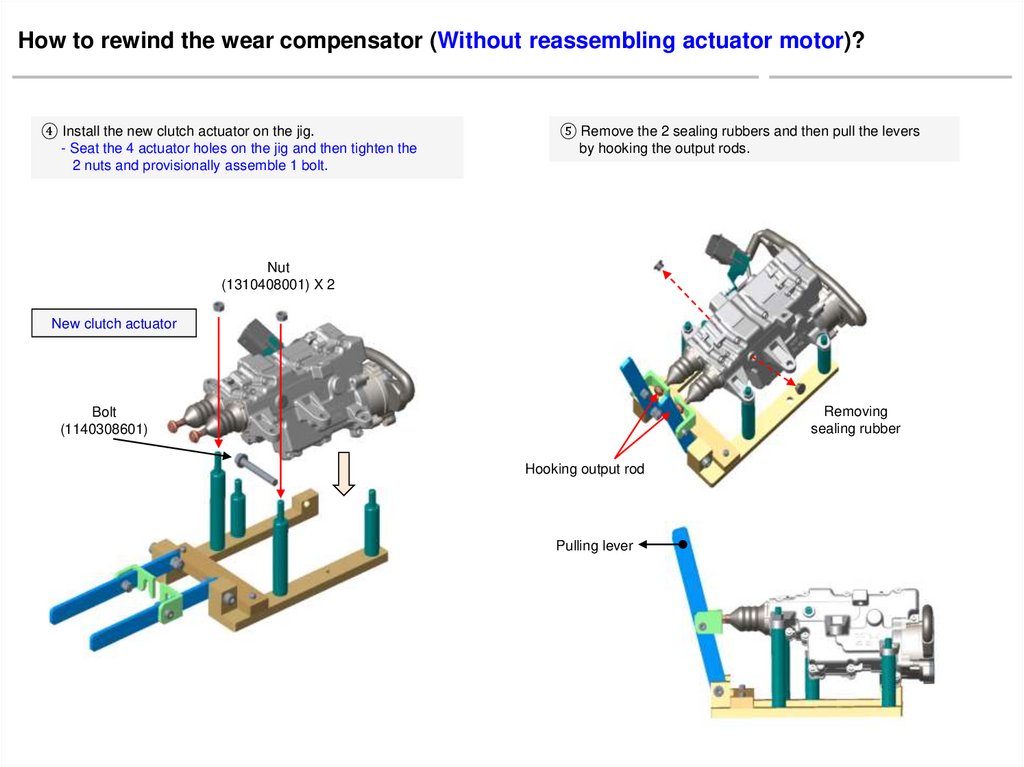
How to rewind the wear compensator (Without reassembling actuator motor)?④ Install the new clutch actuator on the jig.
- Seat the 4 actuator holes on the jig and then tighten the
2 nuts and provisionally assemble 1 bolt.
⑤ Remove the 2 sealing rubbers and then pull the levers
by hooking the output rods.
Nut
(1310408001) X 2
New clutch actuator
Removing
sealing rubber
Bolt
(1140308601)
Hooking output rod
Pulling lever
17.
How to rewind the wear compensator (Without reassembling actuator motor)?⑥ Check the output rod length of new clutch actuator
(Measure the length, slightly pulling the lever to prevent the length
from being reduced by the sealing boot).
- Record the measured output rod length (B1, B2).
▶
Housing
base
line
Output rod length of
new clutch actuator (B1 ≠ L1)
⑦ Stand the clutch actuator vertically with installed to the base jig.
- After standing the clutch actuator vertically, remove the hooks
and levers from the output rods.
Removing hooks and levers after
standing clutch actuator vertically
Lever is pulled slightly
Lever is pulled slightly
Output rod length of
new clutch actuator (B2 ≠ L2)
DCT type
Rod length (B)
[mm] of new
clutch actuator
Medium
7-speed DCT
(D7UF1)
Small
7-speed DCT
(D7GF1)
HEV
6-speed DCT
(D6KF1)
Record the actually measured output rod length
of new clutch actuator
Supporting base jig on the
vertical face as necessary
18.
How to rewind the wear compensator (Without reassembling actuator motor)?⑧ Press the end of output rod until the protrusion of wear compensator nut
appears in the sealing rubber hole and then release the press force.
- Locate the nut inside of the hole by flashing light.
- Repeat this step when nut is not down to the hole.
- When releasing the press force, nut will move slightly upward
by the sealing boot.
Pressing
output rod
⑨ Insert the tool for adjusting the wear compensator into the
sealing rubber hole.
- Insert the tool after aligning the end of tool with the part shape
seen through the sealing rubber hole.
Releasing
press force
Aligned part state seen
through the sealing rubber hole
19.
How to rewind the wear compensator (Without reassembling actuator motor)?⑩ Rotate the tool clockwise as desired for shortening the
output rod length (B) to the previous output rod length (L).
- Rotate the tool counterclockwise when increasing (+) the
output rod length.
- Rotate the tool clockwise when shortening (-) the
output rod length.
⑪ Apply the same procedure (Step ⑧, ⑨, ⑩) to the opposite output
rod.
Rotating tool clockwise as desired
Rotating tool clockwise as desired
- Rotating tool 1 revolution counterclockwise
= Output rod length is increased by 0.25mm
- Rotating tool 1 revolution clockwise
= Output rod length is shortened by 0.25mm
20.
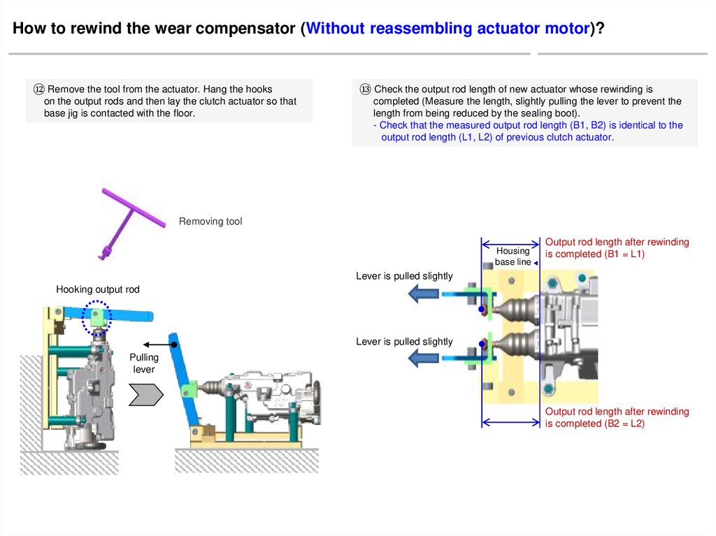
How to rewind the wear compensator (Without reassembling actuator motor)?⑫ Remove the tool from the actuator. Hang the hooks
on the output rods and then lay the clutch actuator so that
base jig is contacted with the floor.
⑬ Check the output rod length of new actuator whose rewinding is
completed (Measure the length, slightly pulling the lever to prevent the
length from being reduced by the sealing boot).
- Check that the measured output rod length (B1, B2) is identical to the
output rod length (L1, L2) of previous clutch actuator.
Removing tool
▶
Housing
base line
Output rod length after rewinding
is completed (B1 = L1)
Lever is pulled slightly
Hooking output rod
Lever is pulled slightly
Pulling
lever
Output rod length after rewinding
is completed (B2 = L2)
21.
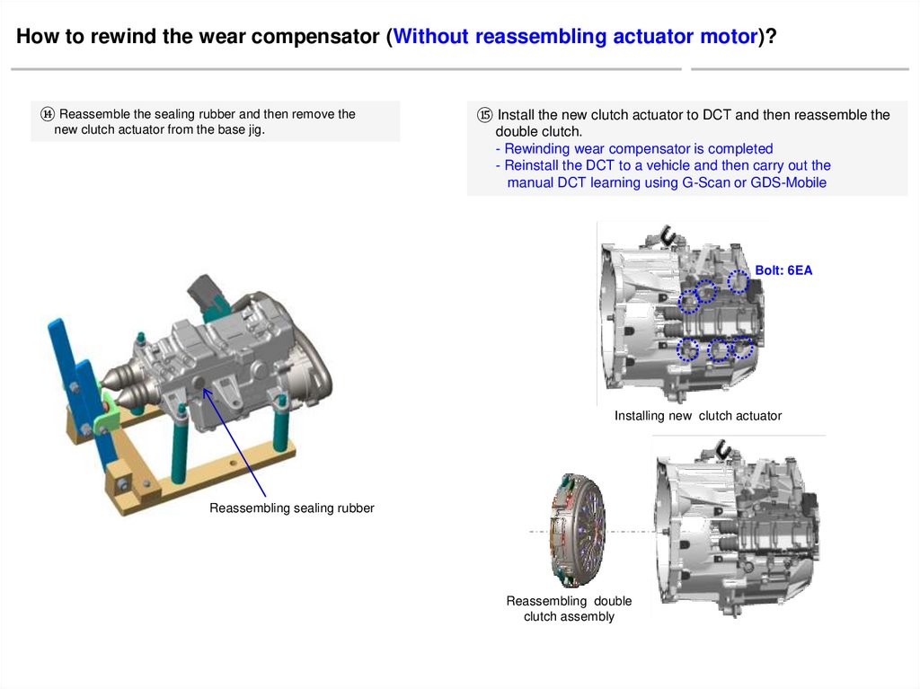
How to rewind the wear compensator (Without reassembling actuator motor)?⑭ Reassemble the sealing rubber and then remove the
new clutch actuator from the base jig.
⑮ Install the new clutch actuator to DCT and then reassemble the
double clutch.
- Rewinding wear compensator is completed
- Reinstall the DCT to a vehicle and then carry out the
manual DCT learning using G-Scan or GDS-Mobile
Bolt: 6EA
Installing new clutch actuator
Reassembling sealing rubber
Reassembling double
clutch assembly
22.
Additional instruction■ Calculation of the number of turns for wear compensator tool
- Calculating formula for the number of turns and rotating direction (+/-)
: (Length after adjustment - Length before adjustment)/Length change
per 1 revolution
[When rewinding wear compensator]
= (Rod length of removed clutch actuator L - Rod length B of
new clutch actuator )/0.25mm
※ Rotate tool counterclockwise to increase (+) the rod length.
Rotate tool clockwise to shorten (-) the rod length.
[Rewinding case of output rod length]
1) Actually measured output rod length (L1, L2) of removed clutch actuator
Rod length for odd gear L1 = 70.0
Rod length for even gear L2 = 68.0
2) Actually measured output rod length (B1, B2) of new clutch actuator
B1 = B2 = 73.0 mm (Medium 7-speed DCT)
3) It is necessary to rewind the output rod length of new clutch actuator
because the rod length (B1, B2) is different to the rod length (L1, L2).
- L1 (70.0) ≠ B1 (73.0)
- L2 (68.0) ≠ B2 (73.0)
4) The number of turns for wear compensator tool
(L1–B1)/0.25=(70.0-73.0)/0.25 = -3.0/0.25= -12 revolutions
(L2–B2)/0.25=(68.0-73.0)/0.25 = -5.0/0.25= -20 revolutions
23.
Servicing method forwear compensator of clutch actuator
when it reaches operating limit
24.
How to service the wear compensator of clutch actuator when it reaches operating limit?① Install the clutch actuator removed from DCT on the jig.
- Seat the 4 actuator holes on the jig and then tighten the
2 nuts and provisionally assemble 1 bolt.
CAUTION
② Check the output rod length of clutch actuator removed from DCT
(Measure the length, slightly pulling the lever to prevent the length
from being reduced by the sealing boot).
- If the measured output rod length (L) is below the operating limit (E),
replace the double clutch assembly, clutch actuator and engagement
bearing at the same time.
No removal of actuator motor is required.
Output rod length of
removed actuator (L)
▶
Housing
base
line
Nut
(1310408001) X 2
Lever is pulled slightly
Bolt
(1140308601)
Lever is pulled slightly
Output rod length of
removed actuator (L)
DCT type
Medium
7-speed DCT
(D7UF1)
Small
7-speed DCT
(D7GF1)
HEV
6-speed DCT
(D6KF1)
Operating limit (E)
[mm]
Below 46
Below 43
Below 57