


 Электроника
Похожие презентации:


Installation and startup. Immersive technologies
1.
INSTALLATION ANDSTARTUP
immersive technologies
THE
IMMERSIVE SOLUTION HUB
Unpacking the Hestia VR terminal
Installation and connections
Startup
Troubleshooting
2.
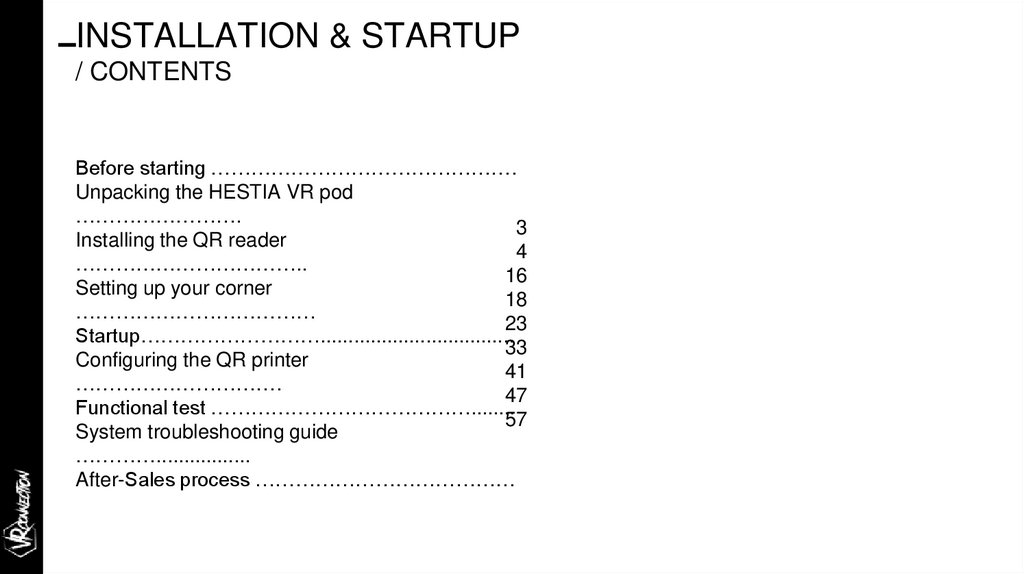
INSTALLATION & STARTUP/ CONTENTS
Before starting ……………………………………….
Unpacking the HESTIA VR pod
…………………….
3
Installing the QR reader
4
……………………………..
16
Setting up your corner
18
………………………………
23
Startup………………………...................................
33
Configuring the QR printer
41
………………………….
47
Functional test …………………………………........
57
System troubleshooting guide
………….................
After-Sales process …………………………………
3.
Before starting,please read this manual.
Dear customer,
The product you have purchased was manufactured in modern factories and checked using strict
quality control procedures. We hope it will give you full satisfaction. Please read the entire manual
carefully before starting to install the product and keep it for reference.
This manual will help you to safely install your product with step-by-step instructions and will guide
you through the startup procedure.
Read the manual before installing and starting up your product.
Please read the safety instructions and the installation conditions.
Keep this manual at hand for future reference.
4.
Unpacking theHESTIA VR pod
immersive technologies
THE
IMMERSIVE SOLUTION HUB
5.
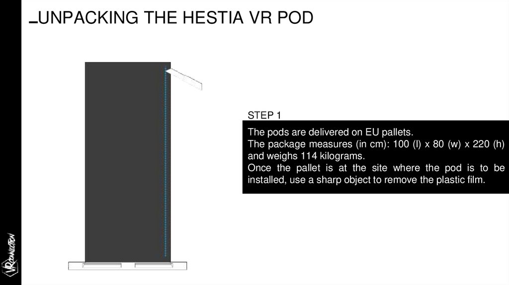
UNPACKING THE HESTIA VR PODSTEP 1
The pods are delivered on EU pallets.
The package measures (in cm): 100 (l) x 80 (w) x 220 (h)
and weighs 114 kilograms.
Once the pallet is at the site where the pod is to be
installed, use a sharp object to remove the plastic film.
6.
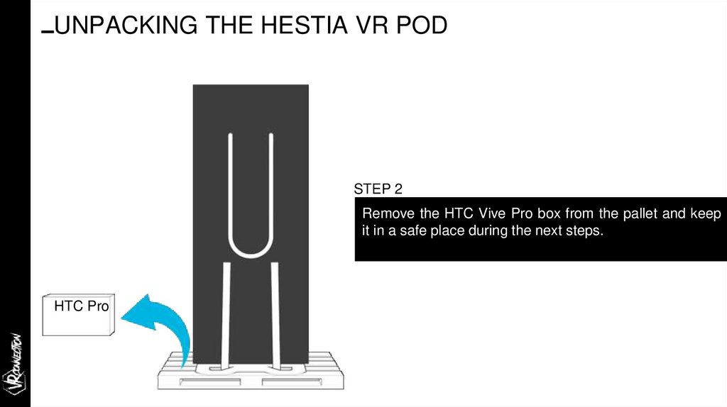
UNPACKING THE HESTIA VR PODSTEP 2
Remove the HTC Vive Pro box from the pallet and keep
it in a safe place during the next steps.
HTC Pro
7.
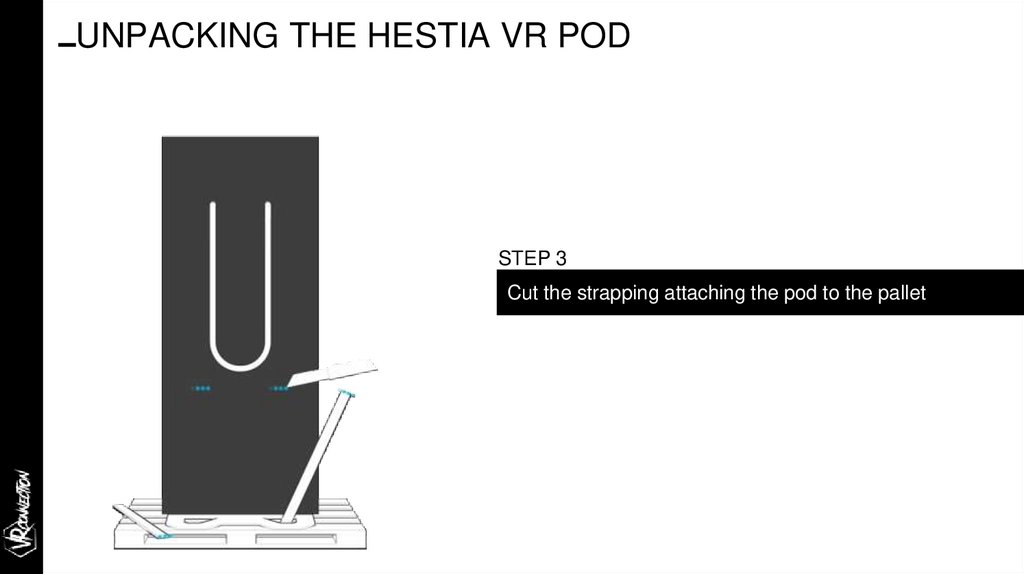
UNPACKING THE HESTIA VR PODSTEP 3
Cut the strapping attaching the pod to the pallet
8.
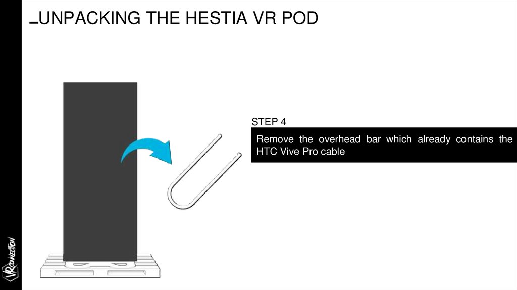
UNPACKING THE HESTIA VR PODSTEP 4
Remove the overhead bar which already contains the
HTC Vive Pro cable
9.
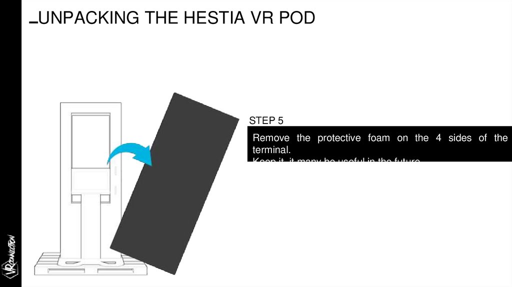
UNPACKING THE HESTIA VR PODSTEP 5
Remove the protective foam on the 4 sides of the
terminal.
Keep it, it many be useful in the future.
10.
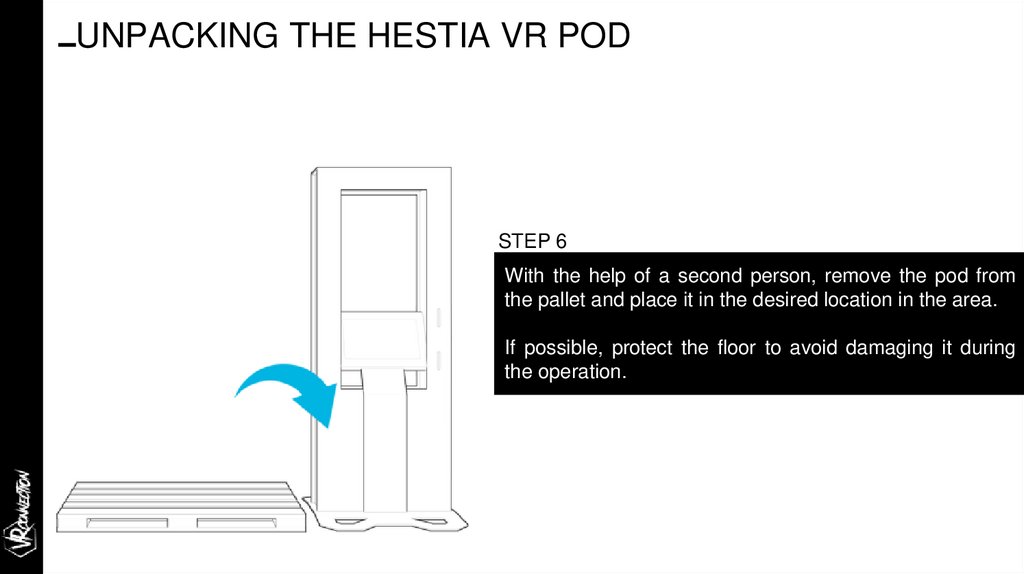
UNPACKING THE HESTIA VR PODSTEP 6
With the help of a second person, remove the pod from
the pallet and place it in the desired location in the area.
If possible, protect the floor to avoid damaging it during
the operation.
11.
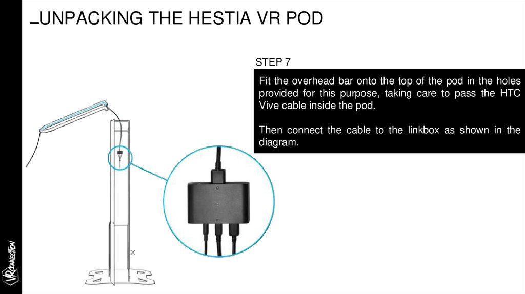
UNPACKING THE HESTIA VR PODSTEP 7
Fit the overhead bar onto the top of the pod in the holes
provided for this purpose, taking care to pass the HTC
Vive cable inside the pod.
Then connect the cable to the linkbox as shown in the
diagram.
12.
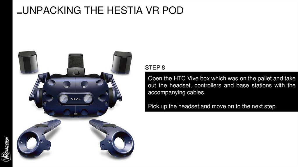
UNPACKING THE HESTIA VR PODSTEP 8
Open the HTC Vive box which was on the pallet and take
out the headset, controllers and base stations with the
accompanying cables.
Pick up the headset and move on to the next step.
13.
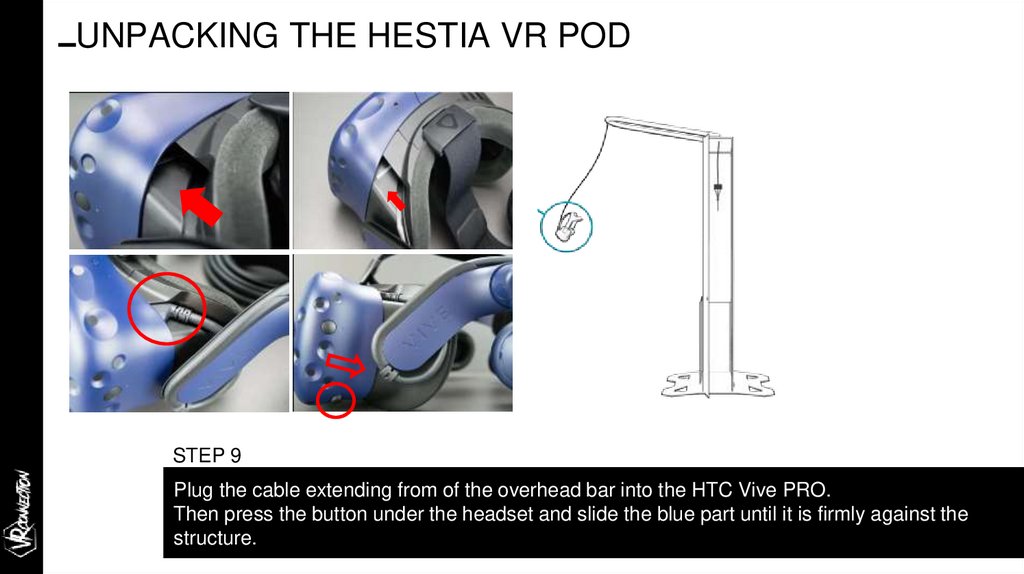
UNPACKING THE HESTIA VR PODSTEP 9
Plug the cable extending from of the overhead bar into the HTC Vive PRO.
Then press the button under the headset and slide the blue part until it is firmly against the
structure.
14.
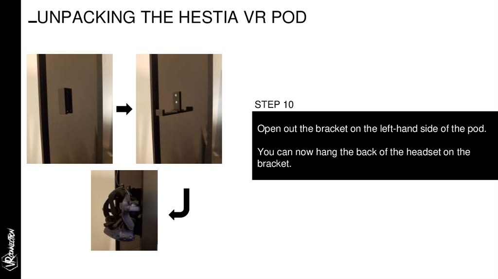
UNPACKING THE HESTIA VR PODSTEP 10
Open out the bracket on the left-hand side of the pod.
You can now hang the back of the headset on the
bracket.
15.
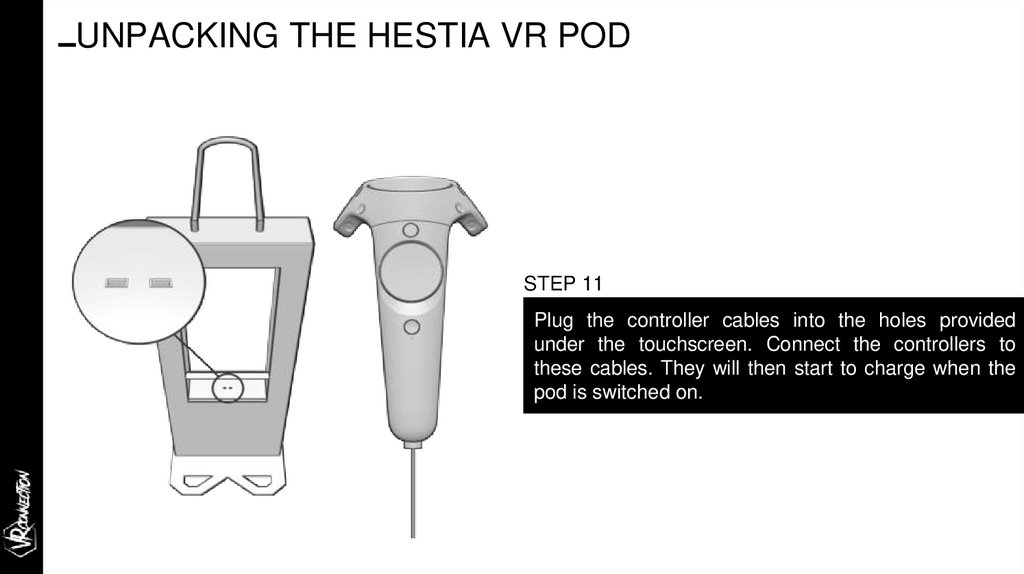
UNPACKING THE HESTIA VR PODSTEP 11
Plug the controller cables into the holes provided
under the touchscreen. Connect the controllers to
these cables. They will then start to charge when the
pod is switched on.
16.
Installing the QR readerimmersive technologies
THE
IMMERSIVE SOLUTION HUB
17.
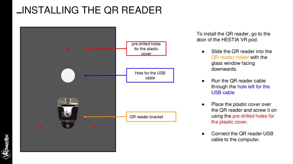
INSTALLING THE QR READERpre-drilled holes
for the plastic
cover
Hole for the USB
cable
To install the QR reader, go to the
door of the HESTIA VR pod.
Slide the QR reader into the
QR reader holder with the
glass window facing
downwards.
Run the QR reader cable
through the hole left for the
USB cable
Place the plastic cover over
the QR reader and screw it on
using the pre-drilled holes for
the plastic cover.
Connect the QR reader USB
cable to the computer.
QR reader bracket
18.
Setting up your corner:ancillary equipment
immersive technologies
THE
IMMERSIVE SOLUTION HUB
19.
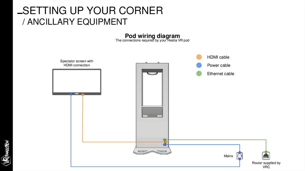
SETTING UP YOUR CORNER/ ANCILLARY EQUIPMENT
Pod wiring diagram
The connections required by your Hestia VR pod
HDMI cable
Spectator screen with
HDMI connection
Power cable
Ethernet cable
Mains
Router supplied by
VRC
20.
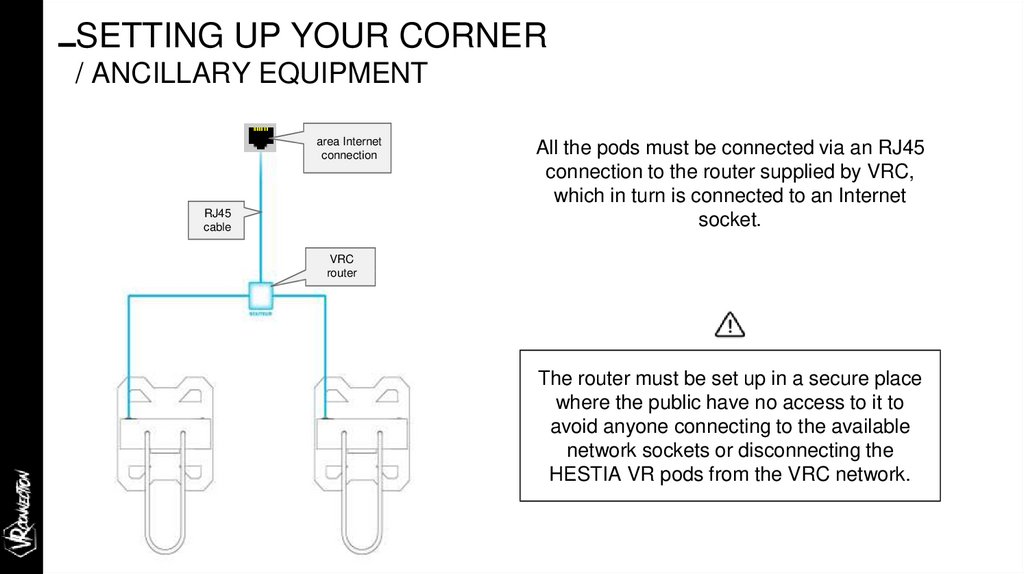
SETTING UP YOUR CORNER/ ANCILLARY EQUIPMENT
area Internet
connection
RJ45
cable
All the pods must be connected via an RJ45
connection to the router supplied by VRC,
which in turn is connected to an Internet
socket.
VRC
router
The router must be set up in a secure place
where the public have no access to it to
avoid anyone connecting to the available
network sockets or disconnecting the
HESTIA VR pods from the VRC network.
21.
SETTING UP YOUR CORNER/ ANCILLARY EQUIPMENT
GAMING
ZONE
GAMING
ZONE
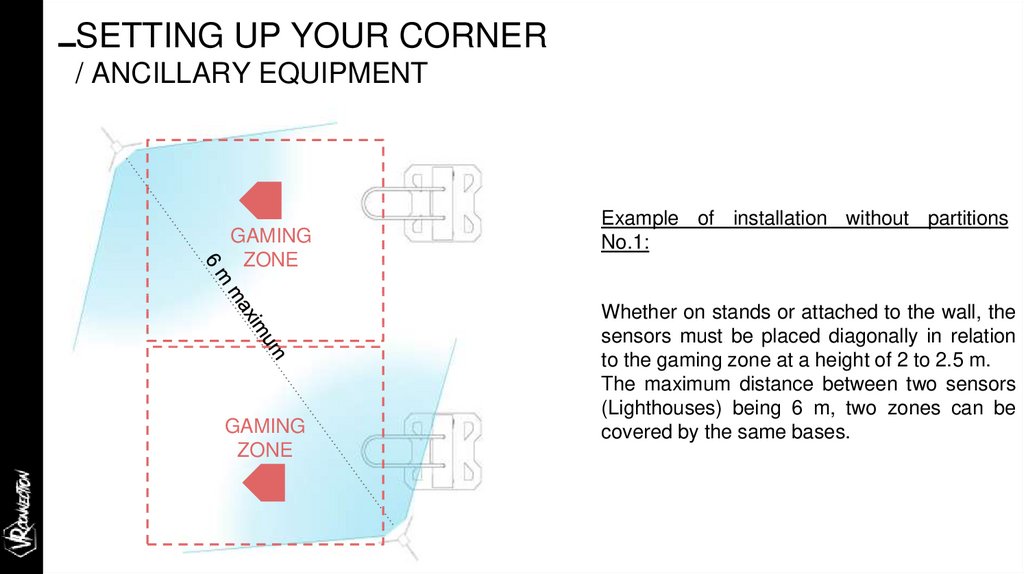
Example of installation without partitions
No.1:
Whether on stands or attached to the wall, the
sensors must be placed diagonally in relation
to the gaming zone at a height of 2 to 2.5 m.
The maximum distance between two sensors
(Lighthouses) being 6 m, two zones can be
covered by the same bases.
22.
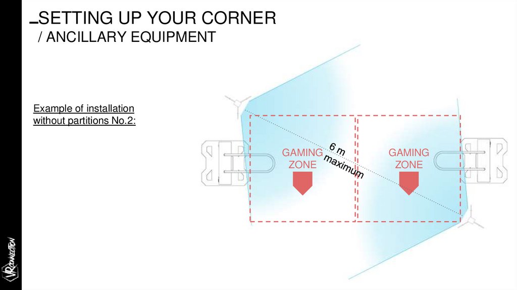
SETTING UP YOUR CORNER/ ANCILLARY EQUIPMENT
Example of installation
without partitions No.2:
GAMING
ZONE
GAMING
ZONE
23.
Startupimmersive technologies
THE
IMMERSIVE SOLUTION HUB
24.
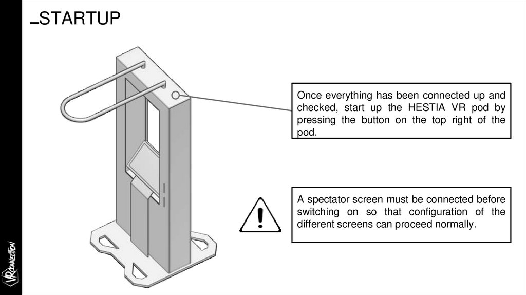
STARTUPOnce everything has been connected up and
checked, start up the HESTIA VR pod by
pressing the button on the top right of the
pod.
A spectator screen must be connected before
switching on so that configuration of the
different screens can proceed normally.
25.
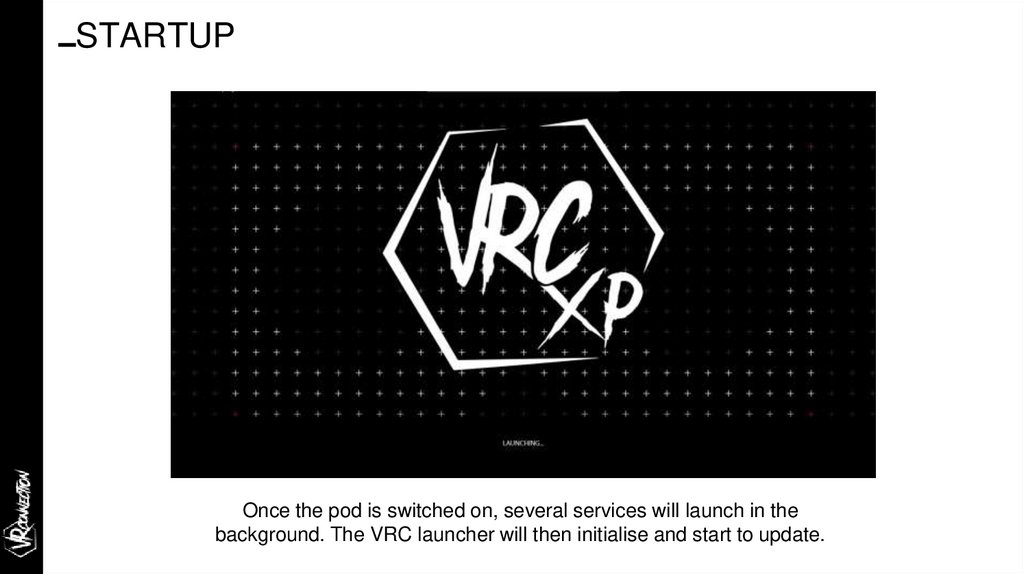
STARTUPOnce the pod is switched on, several services will launch in the
background. The VRC launcher will then initialise and start to update.
26.
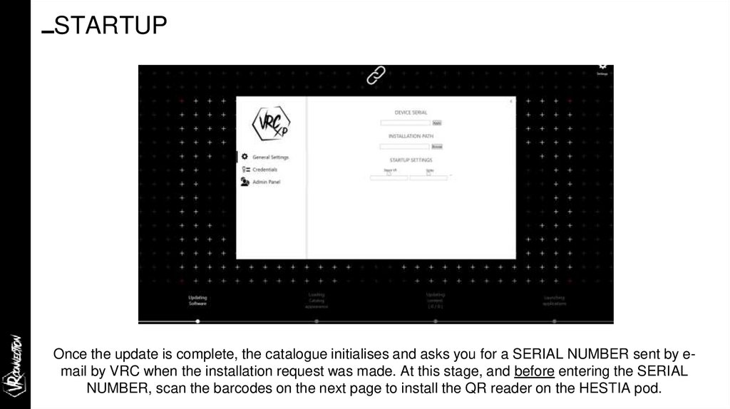
STARTUPOnce the update is complete, the catalogue initialises and asks you for a SERIAL NUMBER sent by email by VRC when the installation request was made. At this stage, and before entering the SERIAL
NUMBER, scan the barcodes on the next page to install the QR reader on the HESTIA pod.
27.
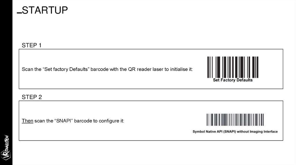
STARTUPSTEP 1
Scan the “Set factory Defaults” barcode with the QR reader laser to initialise it:
STEP 2
Then scan the “SNAPI” barcode to configure it:
28.
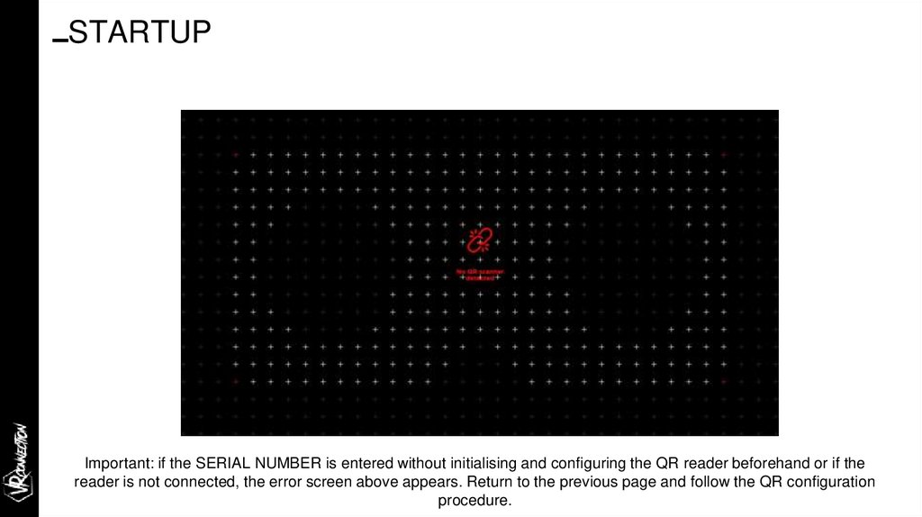
STARTUPImportant: if the SERIAL NUMBER is entered without initialising and configuring the QR reader beforehand or if the
reader is not connected, the error screen above appears. Return to the previous page and follow the QR configuration
procedure.
29.
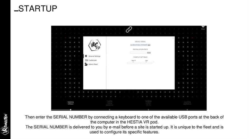
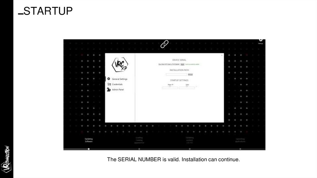
STARTUPThen enter the SERIAL NUMBER by connecting a keyboard to one of the available USB ports at the back of
the computer in the HESTIA VR pod.
The SERIAL NUMBER is delivered to you by e-mail before a site is started up. It is unique to the fleet and is
used to configure its specific features.
30.
STARTUPThe SERIAL NUMBER is valid. Installation can continue.
31.
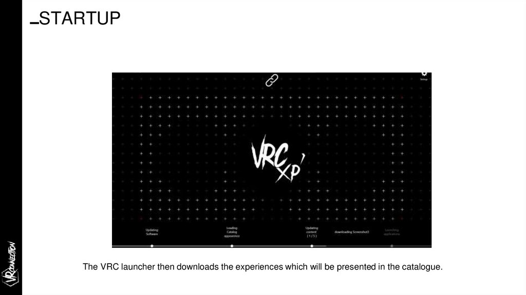
STARTUPThe VRC launcher then downloads the experiences which will be presented in the catalogue.
32.
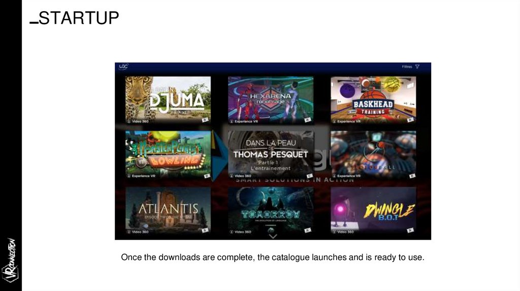
STARTUPOnce the downloads are complete, the catalogue launches and is ready to use.
33.
Configuring the QR printerimmersive technologies
34.
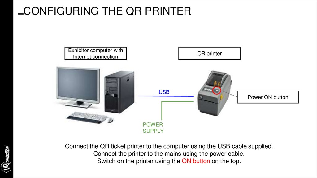
CONFIGURING THE QR PRINTERExhibitor computer with
Internet connection
QR printer
USB
Power ON button
POWER
SUPPLY
Connect the QR ticket printer to the computer using the USB cable supplied.
Connect the printer to the mains using the power cable.
Switch on the printer using the ON button on the top.
35.
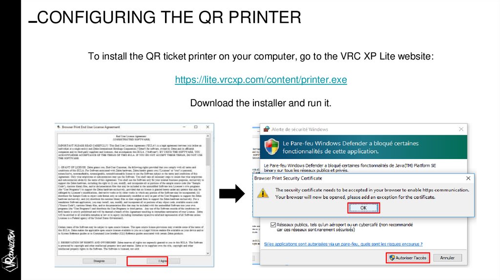
CONFIGURING THE QR PRINTERTo install the QR ticket printer on your computer, go to the VRC XP Lite website:
https://lite.vrcxp.com/content/printer.exe
Download the installer and run it.
36.
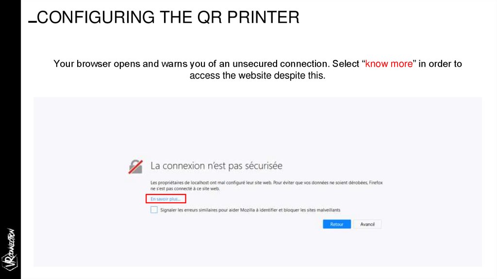
CONFIGURING THE QR PRINTERYour browser opens and warns you of an unsecured connection. Select “know more” in order to
access the website despite this.
37.
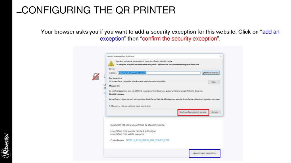
CONFIGURING THE QR PRINTERYour browser asks you if you want to add a security exception for this website. Click on “add an
exception” then “confirm the security exception”.
38.
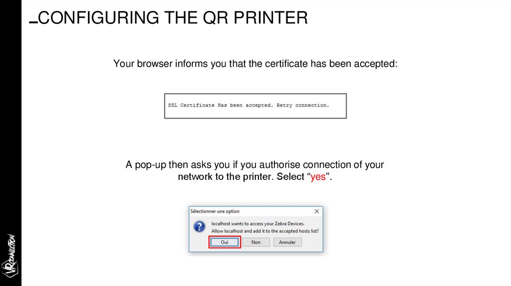
CONFIGURING THE QR PRINTERYour browser informs you that the certificate has been accepted:
A pop-up then asks you if you authorise connection of your
network to the printer. Select “yes”.
39.
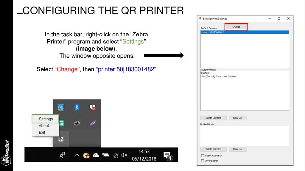
CONFIGURING THE QR PRINTERIn the task bar, right-click on the “Zebra
Printer” program and select “Settings”
(image below).
The window opposite opens.
Select “Change”, then “printer:50j183001482”
40.
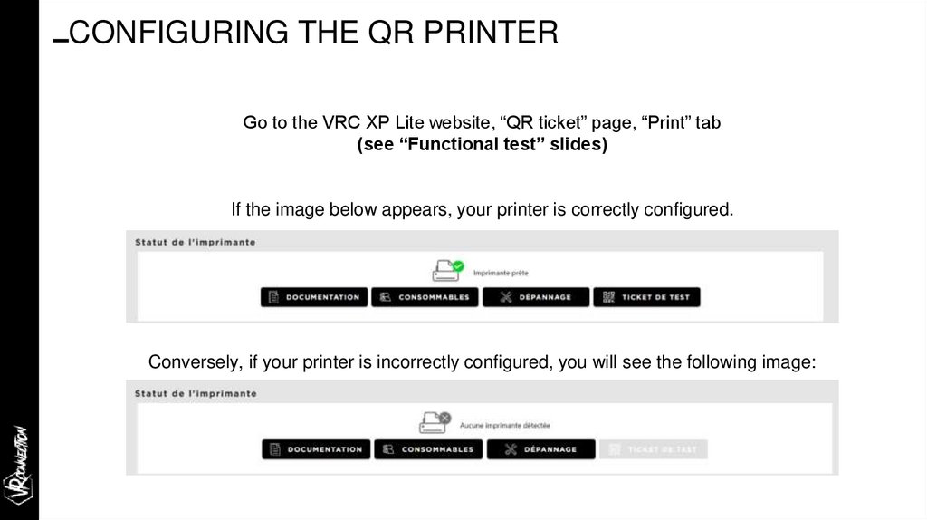
CONFIGURING THE QR PRINTERGo to the VRC XP Lite website, “QR ticket” page, “Print” tab
(see “Functional test” slides)
If the image below appears, your printer is correctly configured.
Conversely, if your printer is incorrectly configured, you will see the following image:
41.
Functional testimmersive technologies
THE
IMMERSIVE SOLUTION HUB
42.
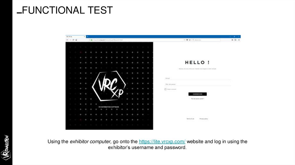
FUNCTIONAL TESTUsing the exhibitor computer, go onto the https://lite.vrcxp.com/ website and log in using the
exhibitor’s username and password.
43.
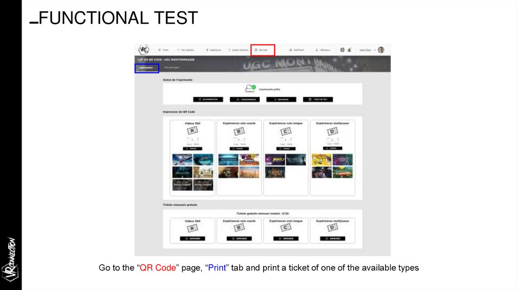
FUNCTIONAL TESTGo to the “QR Code” page, “Print” tab and print a ticket of one of the available types
44.
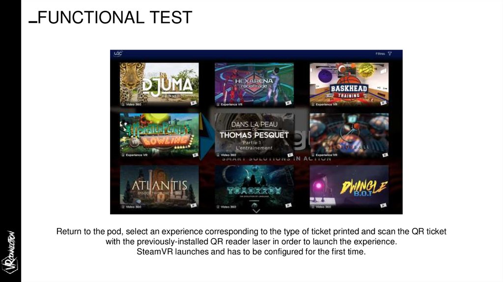
FUNCTIONAL TESTReturn to the pod, select an experience corresponding to the type of ticket printed and scan the QR ticket
with the previously-installed QR reader laser in order to launch the experience.
SteamVR launches and has to be configured for the first time.
45.
FUNCTIONAL TEST/ CONFIGURING THE GAMING AREA
In order to use the HTC VIVE headset properly, the gaming area first needs to be configured.
-
Open the SteamVR window.
(N.B. it opens on its own when
an experience is launched)
-
Click on “SteamVR
” to access the menu then on “Launch the area configuration
wizard”. (NB: This stage opens automatically if an experience is launched but the area
is not configured).
Click on “Room” and follow the instructions on the screen.
-
Once configuration is successfully completed, the experience launches.
-
46.
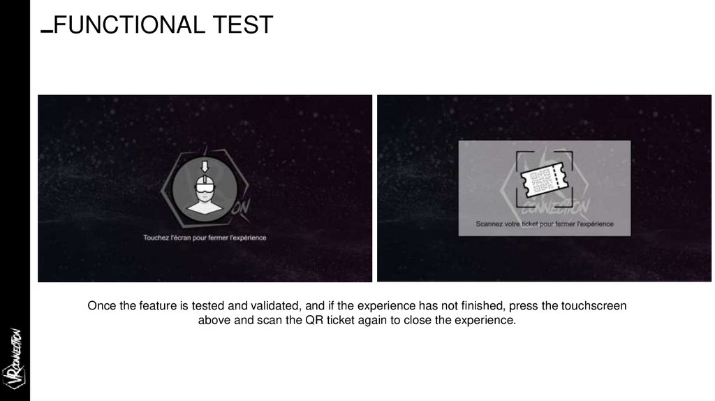
FUNCTIONAL TESTOnce the feature is tested and validated, and if the experience has not finished, press the touchscreen
above and scan the QR ticket again to close the experience.
47.
System troubleshooting guideimmersive technologies
THE
IMMERSIVE SOLUTION HUB
48.
SYSTEM TROUBLESHOOTING GUIDE/ STEAM VR - THE INTERFACE
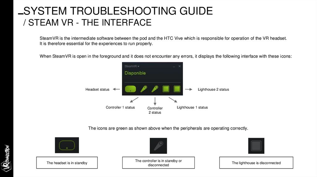
SteamVR is the intermediate software between the pod and the HTC Vive which is responsible for operation of the VR headset.
It is therefore essential for the experiences to run properly.
When SteamVR is open in the foreground and it does not encounter any errors, it displays the following interface with these icons:
Headset status
Controller 1 status
Lighthouse 2 status
Controller
2 status
Lighthouse 1 status
The icons are green as shown above when the peripherals are operating correctly.
The headset is in standby
The controller is in standby or
disconnected
The lighthouse is disconnected
49.
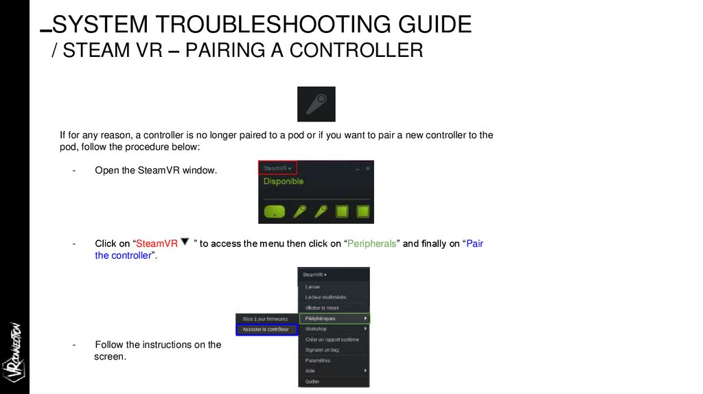
SYSTEM TROUBLESHOOTING GUIDE/ STEAM VR – PAIRING A CONTROLLER
If for any reason, a controller is no longer paired to a pod or if you want to pair a new controller to the
pod, follow the procedure below:
-
Open the SteamVR window.
-
Click on “SteamVR
the controller”.
-
Follow the instructions on the
screen.
” to access the menu then click on “Peripherals” and finally on “Pair
50.
SYSTEM TROUBLESHOOTING GUIDE/ STEAM VR - CONTROLLER DISCONNECTED
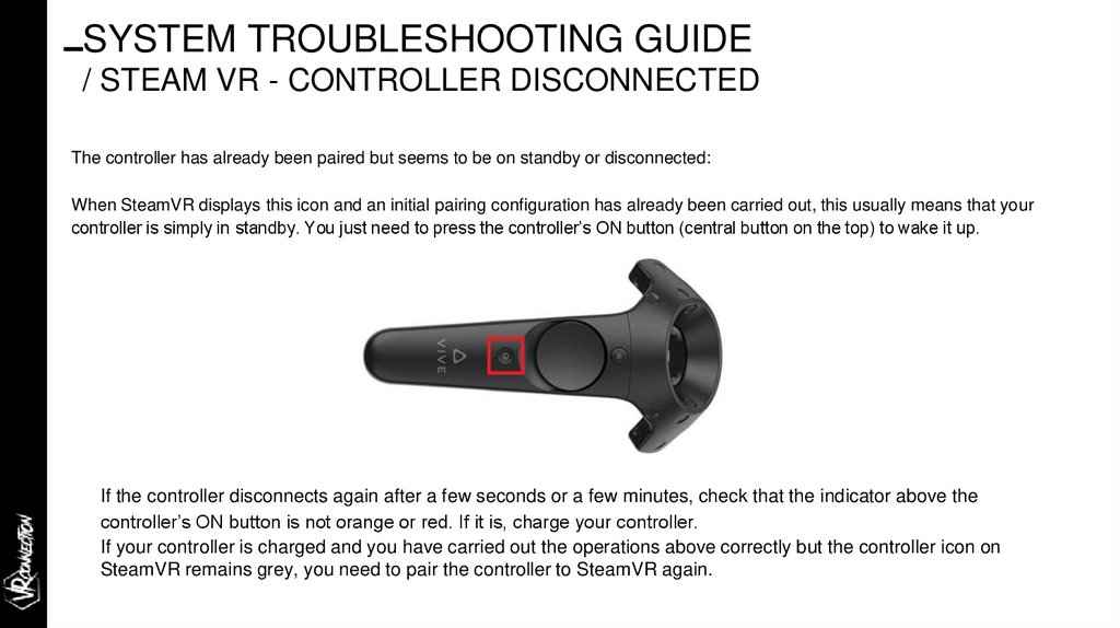
The controller has already been paired but seems to be on standby or disconnected:
When SteamVR displays this icon and an initial pairing configuration has already been carried out, this usually means that your
controller is simply in standby. You just need to press the controller’s ON button (central button on the top) to wake it up.
If the controller disconnects again after a few seconds or a few minutes, check that the indicator above the
controller’s ON button is not orange or red. If it is, charge your controller.
If your controller is charged and you have carried out the operations above correctly but the controller icon on
SteamVR remains grey, you need to pair the controller to SteamVR again.
51.
SYSTEM TROUBLESHOOTING GUIDE/ STEAM VR - AUDIO PROBLEM
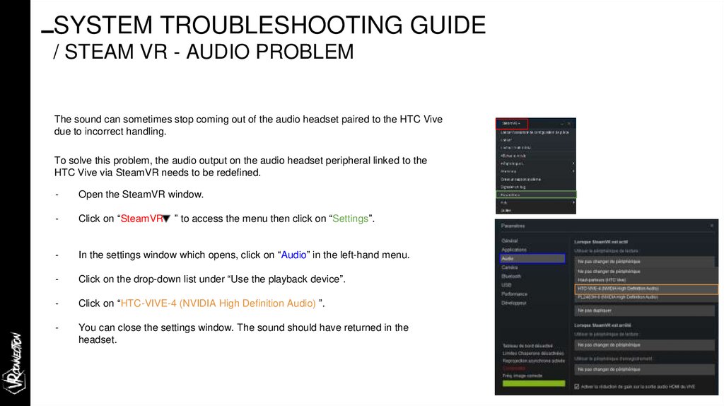
The sound can sometimes stop coming out of the audio headset paired to the HTC Vive
due to incorrect handling.
To solve this problem, the audio output on the audio headset peripheral linked to the
HTC Vive via SteamVR needs to be redefined.
-
Open the SteamVR window.
-
Click on “SteamVR
-
In the settings window which opens, click on “Audio” in the left-hand menu.
-
Click on the drop-down list under “Use the playback device”.
-
Click on “HTC-VIVE-4 (NVIDIA High Definition Audio) ”.
-
You can close the settings window. The sound should have returned in the
headset.
” to access the menu then click on “Settings”.
52.
SYSTEM TROUBLESHOOTING GUIDE/ STEAM VR - 3 BASE STATIONS DISPLAYED
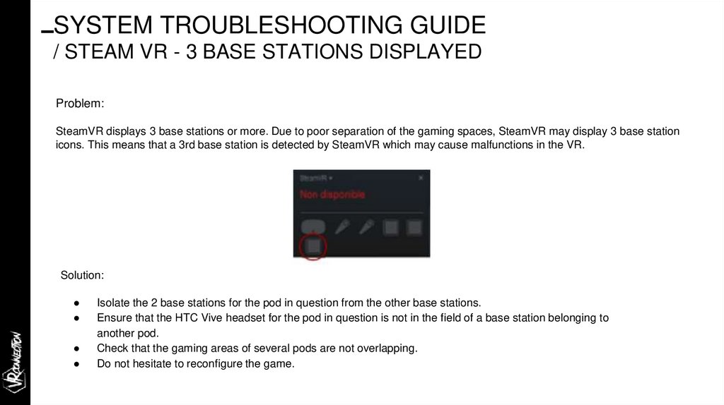
Problem:
SteamVR displays 3 base stations or more. Due to poor separation of the gaming spaces, SteamVR may display 3 base station
icons. This means that a 3rd base station is detected by SteamVR which may cause malfunctions in the VR.
Solution:
Isolate the 2 base stations for the pod in question from the other base stations.
Ensure that the HTC Vive headset for the pod in question is not in the field of a base station belonging to
another pod.
Check that the gaming areas of several pods are not overlapping.
Do not hesitate to reconfigure the game.
53.
SYSTEM TROUBLESHOOTING GUIDE/ STEAM VR - UPDATING THE MICROPROGRAMS (1 / 3)
1.
2.
3.
4.
If you see the
icon, pass the mouse over it to check if the microprogram is no longer up-to-date.
Click on Update the headset microprogram. Updating the microprogram starts automatically.
Warning: Do not disconnect any cables from the headset, connection box or your computer at any time
before the microprogram update has finished. This may lead to a microprogram error.
Once the update has finished, click on OK.
54.
SYSTEM TROUBLESHOOTING GUIDE/ STEAM VR - UPDATING THE MICROPROGRAMS (2 / 3)
1.
2.
3.
4.
5.
6.
7.
Click on “Steam VR
” > Settings > General > Install the Bluetooth pilot.
After installing the Bluetooth pilot, restart the computer.
Restart the SteamVR application.
Click on “Steam VR
” > Settings > Activate Bluetooth communication.
Proceed using one of the following methods:
● Click on “Steam VR
” > Peripherals. Click on Update the microprogram, then select the base
stations.
● If you see the
icon, pass the mouse over it to check if the microprogram is no longer up-to-date. If
this is the case, click on Update the base station microprogram.
Follow the instructions on the screen to complete the process.
Warning: Do not disconnect the power cable at any time before the microprogram update has finished. This may
lead to a microprogram error.
55.
SYSTEM TROUBLESHOOTING GUIDE/ STEAM VR - UPDATING THE MICROPROGRAMS (3 / 3)
1.
2.
3.
4.
5.
If you see the
icon, move the mouse over it to check if the microprogram is no longer up-to-date. If this is
the case, click on Update the controller firmware.
Use a micro-USB cable to connect the controllers to one of the USB ports on your computer one at a time.
Once the controller is detected by the SteamVR application, the microprogram update starts automatically.
Warning: Do not disconnect the micro-USB cable at any time before the microprogram update has finished.
This may lead to a microprogram error.
Once the update has finished, click on End.
56.
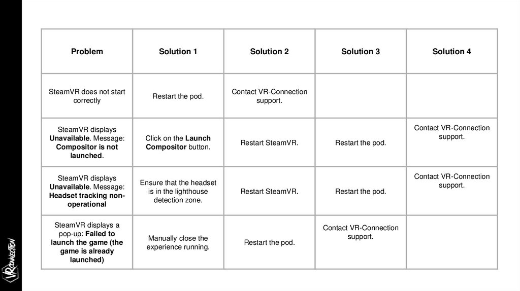
ProblemSolution 1
Solution 2
SteamVR does not start
correctly
Restart the pod.
Contact VR-Connection
support.
SteamVR displays
Unavailable. Message:
Compositor is not
launched.
Click on the Launch
Compositor button.
SteamVR displays
Unavailable. Message:
Headset tracking nonoperational
Ensure that the headset
is in the lighthouse
detection zone.
SteamVR displays a
pop-up: Failed to
launch the game (the
game is already
launched)
Manually close the
experience running.
Restart SteamVR.
Restart SteamVR.
Restart the pod.
Solution 3
Restart the pod.
Restart the pod.
Contact VR-Connection
support.
Solution 4
Contact VR-Connection
support.
Contact VR-Connection
support.
57.
After-Sales processimmersive technologies
THE
IMMERSIVE SOLUTION HUB
58.
Before starting,please refer to the maintenance contract.
The maintenance process is defined on 3 levels:
LEVEL 1: This covers all the problems which can be solved by reading the documentation
on the VRC online guide (vr-connection.zendesk.com).
LEVEL 2: If the problem cannot be solved using the documentation, creating a support
ticket will enable VR-Connection to examine the problem more thoroughly. A ticket must be
sent to our support team, together with photos and descriptions, using the “Create a
request” button in the online guide.
LEVEL 3: according to the seriousness of the problem (minor, major, critical) VRConnection has a contractual commitment with regard to the time to restore to service.
59.
AFTER-SALES PROCESS/ VRC ONLINE GUIDE
The VRC online guide is a website grouping all the documentation necessary for installation,
operation and troubleshooting the VRCXP Lite and HESTIA VR systems.
Available at http://vr-connection.zendesk.com, this website has two parts:
The written guides available in the form of articles.
A support ticketing system to contact an agent in charge of problem-solving.
60.
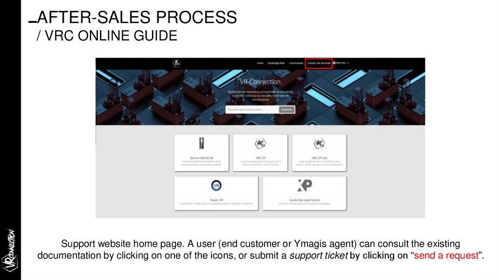
AFTER-SALES PROCESS/ VRC ONLINE GUIDE
Support website home page. A user (end customer or Ymagis agent) can consult the existing
documentation by clicking on one of the icons, or submit a support ticket by clicking on “send a request”.
61.
AFTER-SALES PROCESS/ VRC ONLINE GUIDE
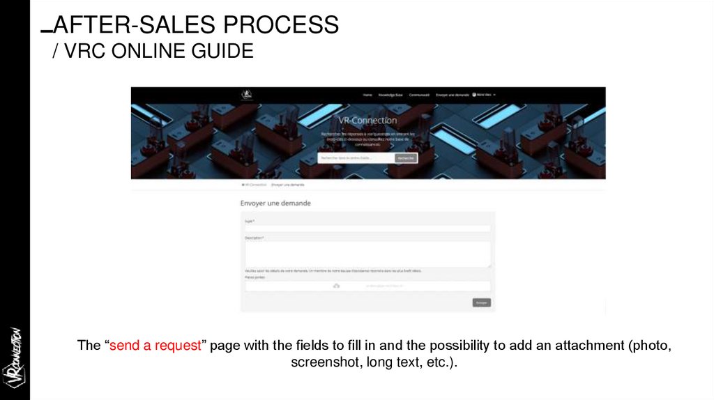
The “send a request” page with the fields to fill in and the possibility to add an attachment (photo,
screenshot, long text, etc.).
62.
AFTER-SALES PROCESS/ VRC ONLINE GUIDE
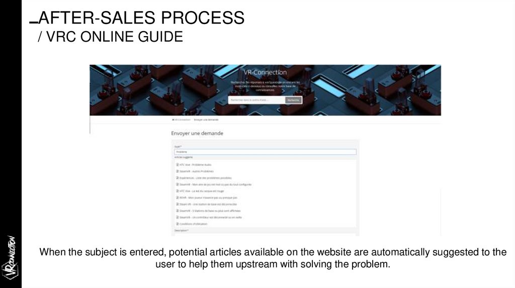
When the subject is entered, potential articles available on the website are automatically suggested to the
user to help them upstream with solving the problem.
63.
AFTER-SALES PROCESS/ VRC ONLINE GUIDE
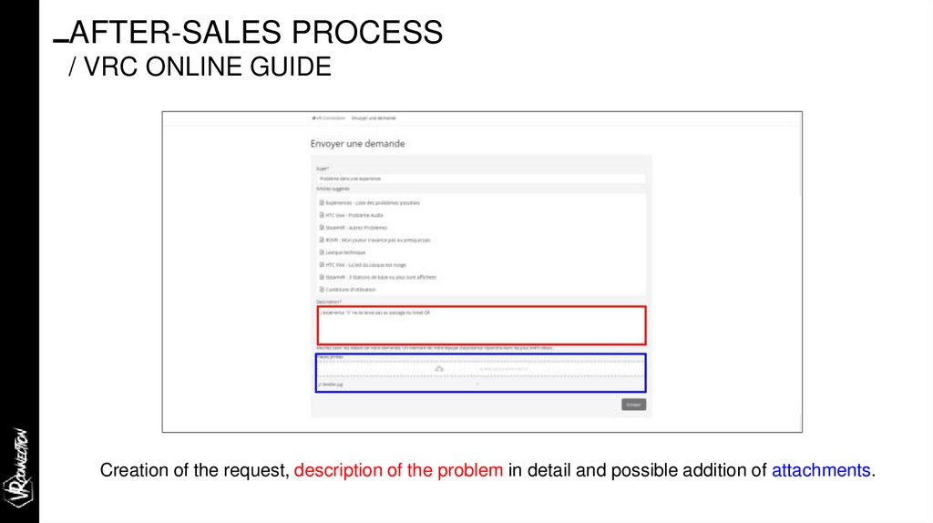
Creation of the request, description of the problem in detail and possible addition of attachments.
64.
AFTER-SALES PROCESS/ VRC ONLINE GUIDE
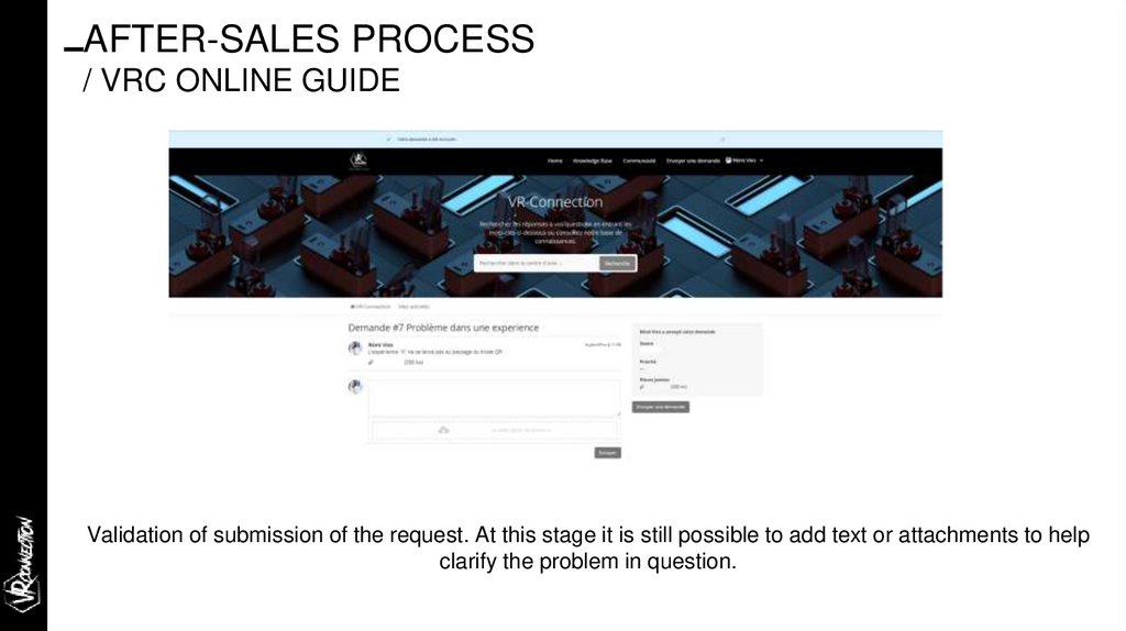
Validation of submission of the request. At this stage it is still possible to add text or attachments to help
clarify the problem in question.
65.
AFTER-SALES PROCESS/ VRC ONLINE GUIDE
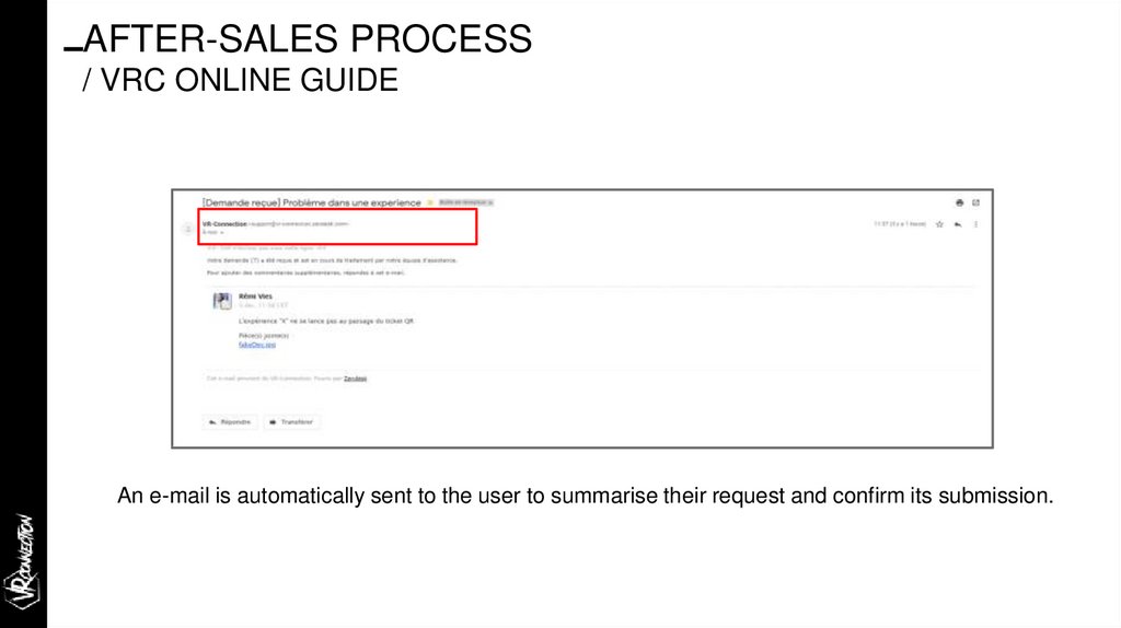
An e-mail is automatically sent to the user to summarise their request and confirm its submission.
66.
AFTER-SALES PROCESS/ VRC ONLINE GUIDE
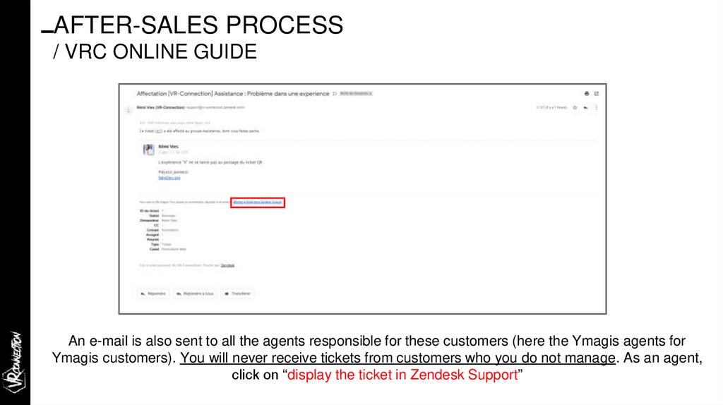
An e-mail is also sent to all the agents responsible for these customers (here the Ymagis agents for
Ymagis customers). You will never receive tickets from customers who you do not manage. As an agent,
click on “display the ticket in Zendesk Support”
67.
AFTER-SALES PROCESS/ VRC ONLINE GUIDE
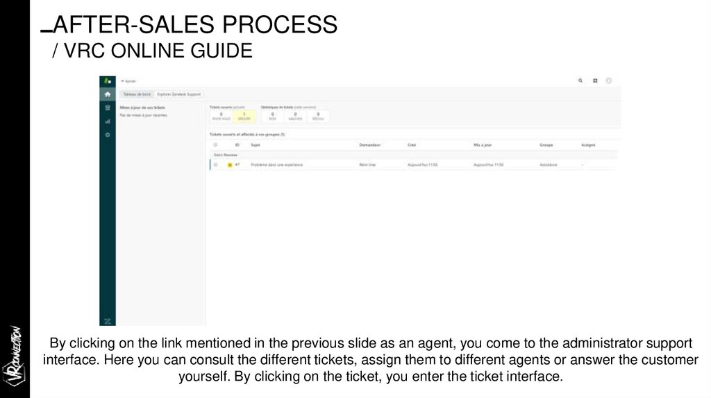
By clicking on the link mentioned in the previous slide as an agent, you come to the administrator support
interface. Here you can consult the different tickets, assign them to different agents or answer the customer
yourself. By clicking on the ticket, you enter the ticket interface.
68.
AFTER-SALES PROCESS/ VRC ONLINE GUIDE
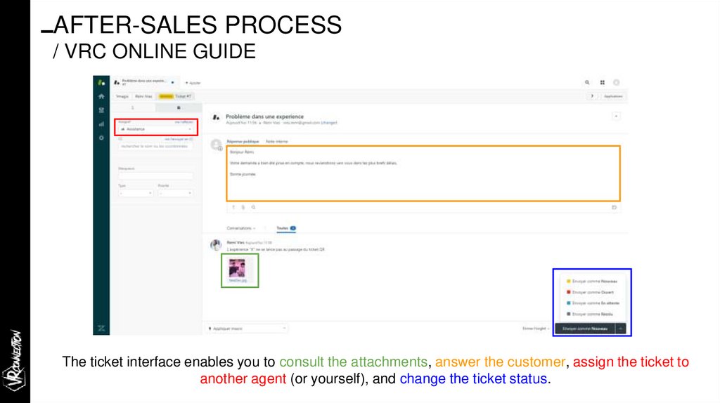
The ticket interface enables you to consult the attachments, answer the customer, assign the ticket to
another agent (or yourself), and change the ticket status.
69.
AFTER-SALES PROCESS/ VRC ONLINE GUIDE
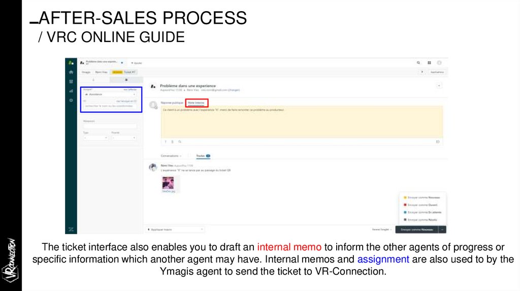
The ticket interface also enables you to draft an internal memo to inform the other agents of progress or
specific information which another agent may have. Internal memos and assignment are also used to by the
Ymagis agent to send the ticket to VR-Connection.
70.
AFTER-SALES PROCESS/ VRC ONLINE GUIDE
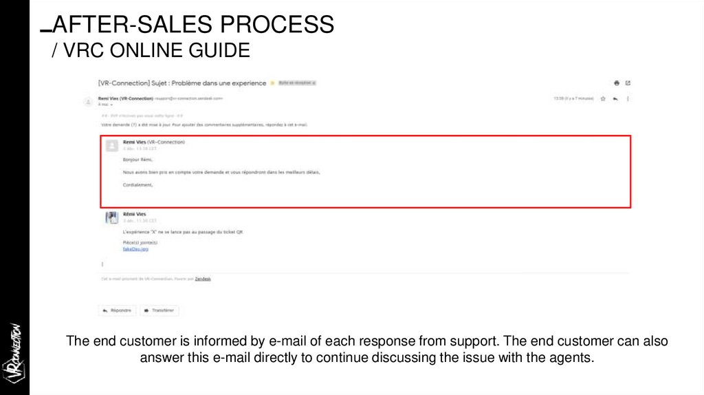
The end customer is informed by e-mail of each response from support. The end customer can also
answer this e-mail directly to continue discussing the issue with the agents.
71.
AFTER-SALES PROCESS/ VRC ONLINE GUIDE
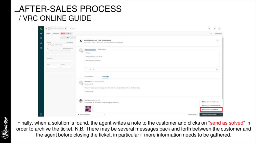
Finally, when a solution is found, the agent writes a note to the customer and clicks on “send as solved” in
order to archive the ticket. N.B. There may be several messages back and forth between the customer and
the agent before closing the ticket, in particular if more information needs to be gathered.
72.
AFTER-SALES PROCESS/ VRC ONLINE GUIDE
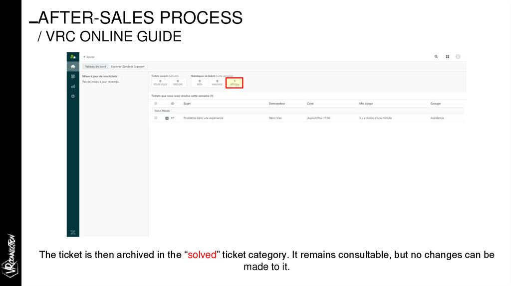
The ticket is then archived in the “solved” ticket category. It remains consultable, but no changes can be
made to it.
73.
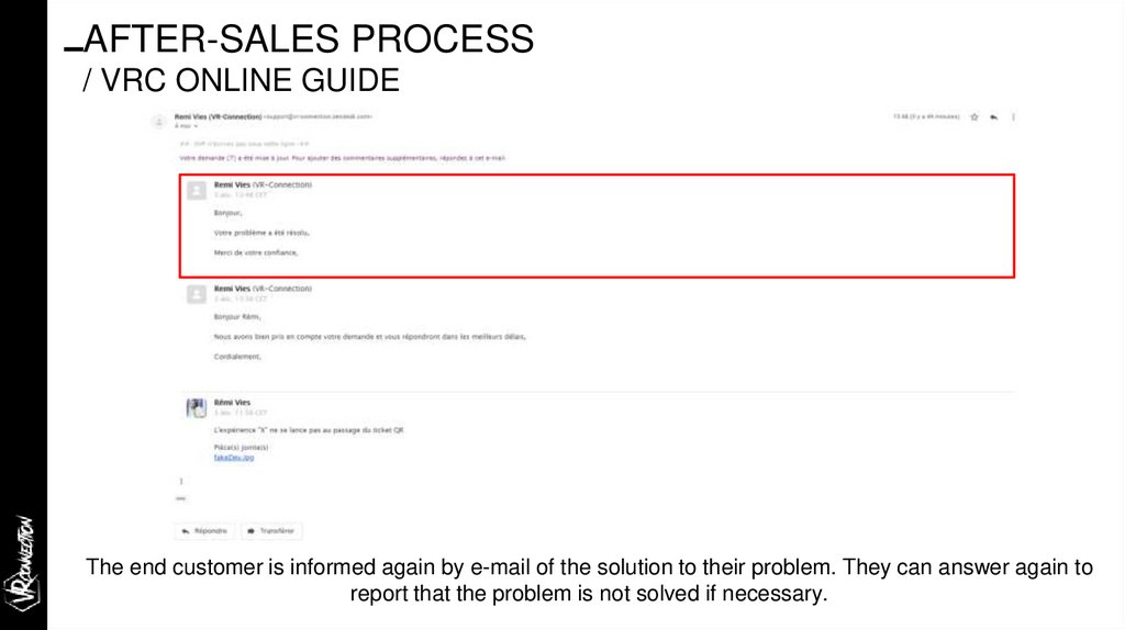
AFTER-SALES PROCESS/ VRC ONLINE GUIDE
The end customer is informed again by e-mail of the solution to their problem. They can answer again to
report that the problem is not solved if necessary.