


 Интернет
Похожие презентации:
")


Network Infrastructure
1.
Lecture 4Network
Infrastructure
1
2.
Objectives1. Describe wired network characteristics and cable
types.
2. Compare and contrast wired network topologies.
3. Compare and contrast common wireless network
configurations.
4. Determine Wireless Distribution Service (WDS).
5. Compare wireless network security options.
6. Describe the purpose and
use of key network
technologies:
• Network Segmentation
• Firewall and Perimeter Network
• Network Address Translation (NAT)
• Proxy Server
• Virtual Private Network (VPN)
2
3.
NetworkInfrastructure
1. Describe wired network
characteristics and cable types
3
4.
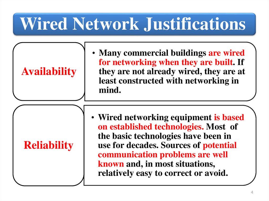
Wired Network JustificationsAvailability
• Many commercial buildings are wired
for networking when they are built. If
they are not already wired, they are at
least constructed with networking in
mind.
Reliability
• Wired networking equipment is based
on established technologies. Most of
the basic technologies have been in
use for decades. Sources of potential
communication problems are well
known and, in most situations,
relatively easy to correct or avoid.
4
5.
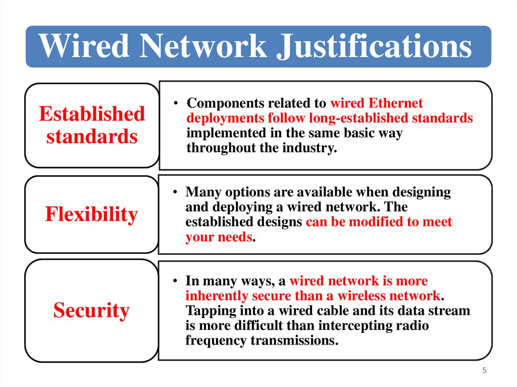
Wired Network JustificationsEstablished
standards
Flexibility
Security
• Components related to wired Ethernet
deployments follow long-established standards
implemented in the same basic way
throughout the industry.
• Many options are available when designing
and deploying a wired network. The
established designs can be modified to meet
your needs.
• In many ways, a wired network is more
inherently secure than a wireless network.
Tapping into a wired cable and its data stream
is more difficult than intercepting radio
frequency transmissions.
5
6.
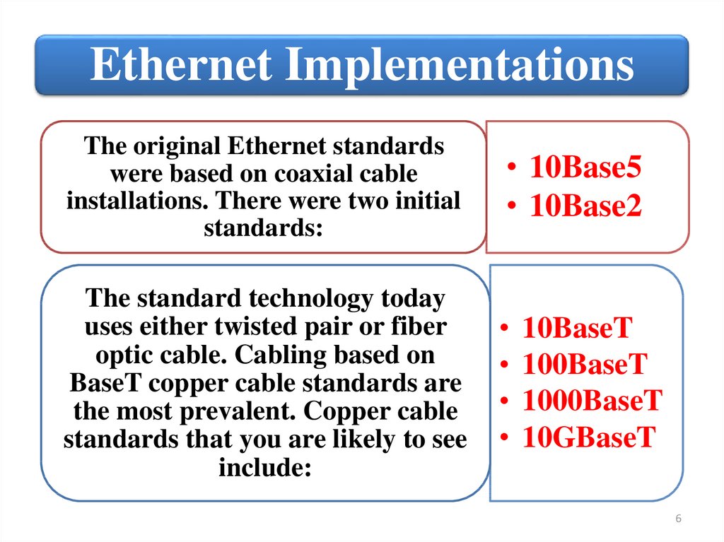
Ethernet ImplementationsThe original Ethernet standards
were based on coaxial cable
installations. There were two initial
standards:
• 10Base5
• 10Base2
The standard technology today
uses either twisted pair or fiber
optic cable. Cabling based on
BaseT copper cable standards are
the most prevalent. Copper cable
standards that you are likely to see
include:
10BaseT
100BaseT
1000BaseT
10GBaseT
6
7.
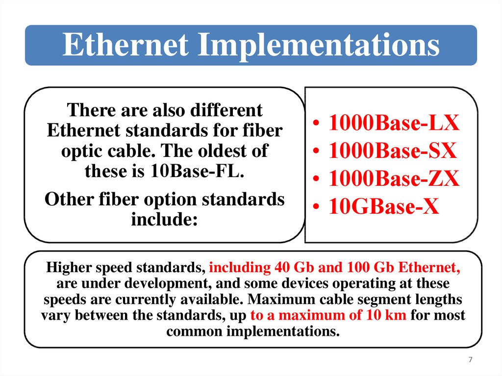
Ethernet ImplementationsThere are also different
Ethernet standards for fiber
optic cable. The oldest of
these is 10Base‐FL.
Other fiber option standards
include:
1000Base‐LX
1000Base‐SX
1000Base‐ZX
10GBase‐X
Higher speed standards, including 40 Gb and 100 Gb Ethernet,
are under development, and some devices operating at these
speeds are currently available. Maximum cable segment lengths
vary between the standards, up to a maximum of 10 km for most
common implementations.
7
8.
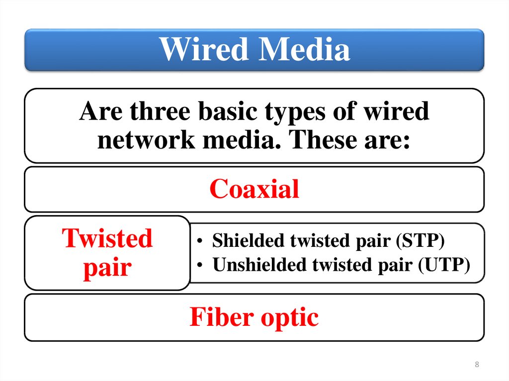
Wired MediaAre three basic types of wired
network media. These are:
Coaxial
Twisted
pair
• Shielded twisted pair (STP)
• Unshielded twisted pair (UTP)
Fiber optic
8
9.
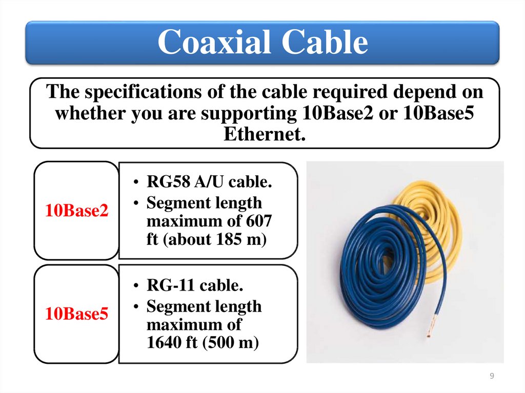
Coaxial CableThe specifications of the cable required depend on
whether you are supporting 10Base2 or 10Base5
Ethernet.
10Base2
• RG58 A/U cable.
• Segment length
maximum of 607
ft (about 185 m)
10Base5
• RG-11 cable.
• Segment length
maximum of
1640 ft (500 m)
9
10.
AttenuationMaximum cable lengths with any type of cable are due to
physical characteristics of the cable and the signal it
carries. A signal loses strength over distance, a process
known as attenuation. After traveling a specific distance,
the signal is no longer reliable. This is true of both wired
and wireless transmissions.
10
11.
ConnectorCoaxial cable has fallen out of
favor for network implement
ations. It is relatively difficult
to work with, and coaxial
cable is not flexible enough to
bend at sharp angles.
Coaxial‐based configurations
are also notoriously difficult
to troubleshoot.
10Base2 had devices
connecting directly to
the cable in a branching
or daisy‐chain
configuration.
Connections were made
using a BNC connector.
11
12.
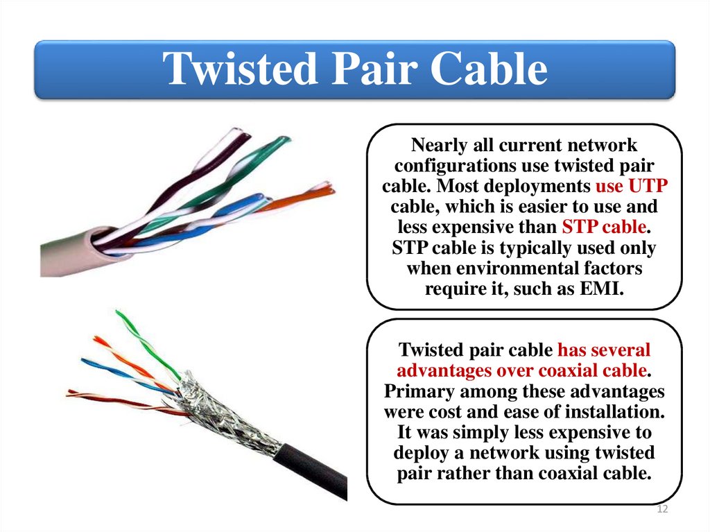
Twisted Pair CableNearly all current network
configurations use twisted pair
cable. Most deployments use UTP
cable, which is easier to use and
less expensive than STP cable.
STP cable is typically used only
when environmental factors
require it, such as EMI.
Twisted pair cable has several
advantages over coaxial cable.
Primary among these advantages
were cost and ease of installation.
It was simply less expensive to
deploy a network using twisted
pair rather than coaxial cable.
12
13.
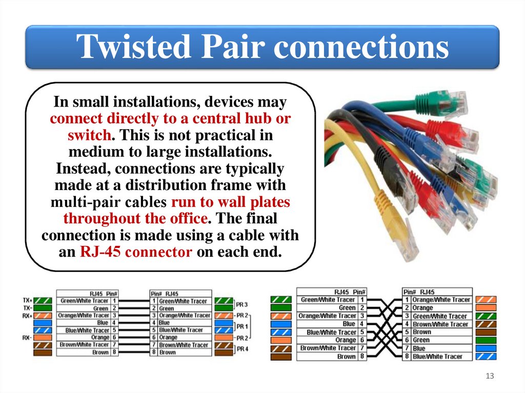
Twisted Pair connectionsIn small installations, devices may
connect directly to a central hub or
switch. This is not practical in
medium to large installations.
Instead, connections are typically
made at a distribution frame with
multi‐pair cables run to wall plates
throughout the office. The final
connection is made using a cable with
an RJ‐45 connector on each end.
13
14.
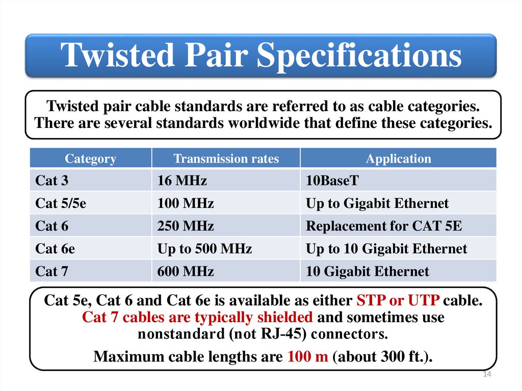
Twisted Pair SpecificationsTwisted pair cable standards are referred to as cable categories.
There are several standards worldwide that define these categories.
Category
Transmission rates
Application
Cat 3
16 MHz
10BaseT
Cat 5/5e
100 MHz
Up to Gigabit Ethernet
Cat 6
250 MHz
Replacement for CAT 5E
Cat 6e
Up to 500 MHz
Up to 10 Gigabit Ethernet
Cat 7
600 MHz
10 Gigabit Ethernet
Cat 5e, Cat 6 and Cat 6e is available as either STP or UTP cable.
Cat 7 cables are typically shielded and sometimes use
nonstandard (not RJ‐45) connectors.
Maximum cable lengths are 100 m (about 300 ft.).
14
15.
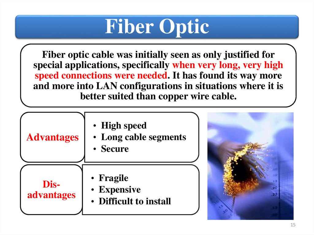
Fiber OpticFiber optic cable was initially seen as only justified for
special applications, specifically when very long, very high
speed connections were needed. It has found its way more
and more into LAN configurations in situations where it is
better suited than copper wire cable.
Advantages
• High speed
• Long cable segments
• Secure
Disadvantages
• Fragile
• Expensive
• Difficult to install
15
16.
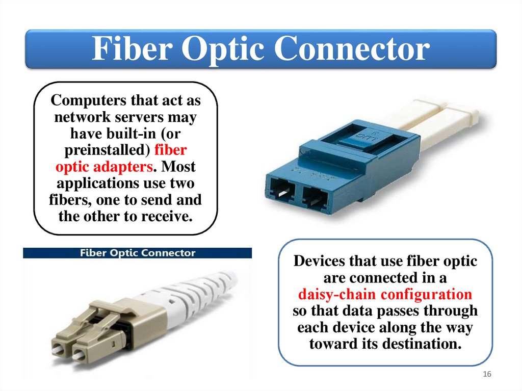
Fiber Optic ConnectorComputers that act as
network servers may
have built‐in (or
preinstalled) fiber
optic adapters. Most
applications use two
fibers, one to send and
the other to receive.
Devices that use fiber optic
are connected in a
daisy‐chain configuration
so that data passes through
each device along the way
toward its destination.
16
17.
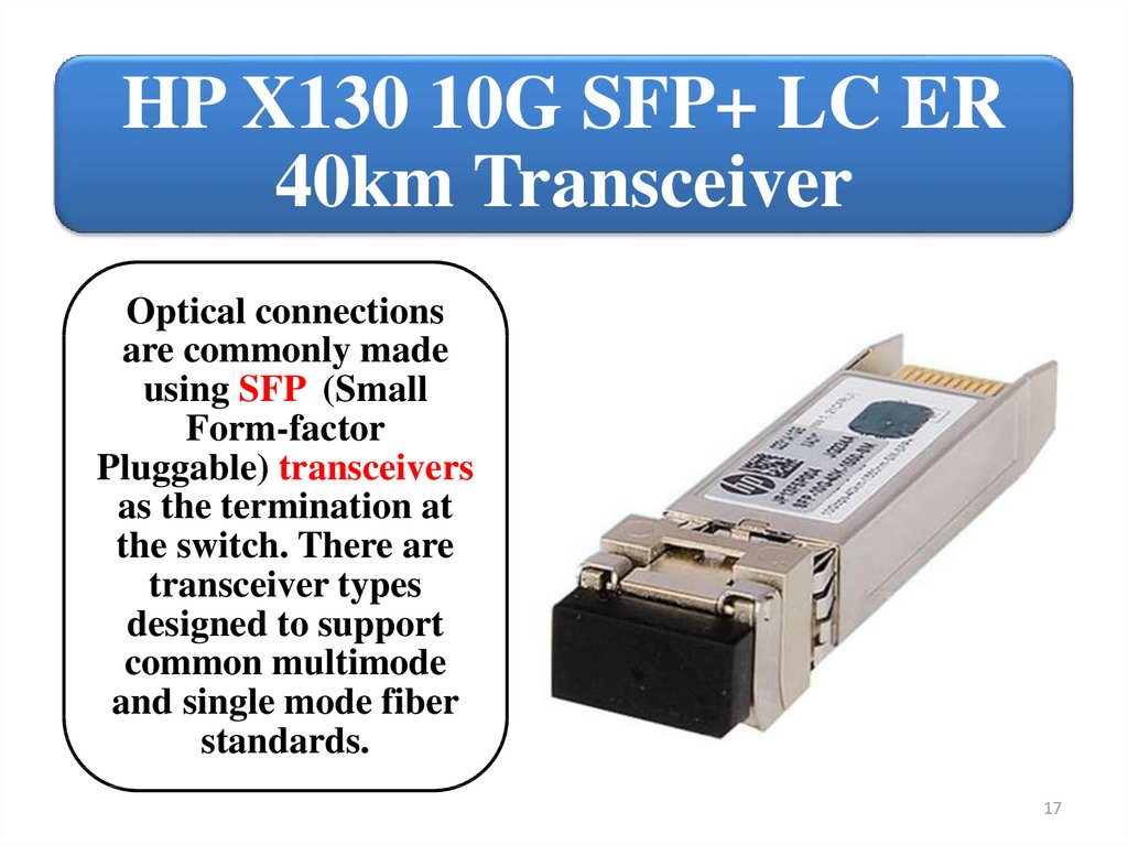
HP X130 10G SFP+ LC ER40km Transceiver
Optical connections
are commonly made
using SFP (Small
Form-factor
Pluggable) transceivers
as the termination at
the switch. There are
transceiver types
designed to support
common multimode
and single mode fiber
standards.
17
18.
SummaryJustifications for wired networks.
Wired network standards.
Wired network cable options and twisted
pair cable categories.
Fiber Optic applications.
18
19.
NetworkInfrastructure
2. Compare and contrast wired
network topologies
19
20.
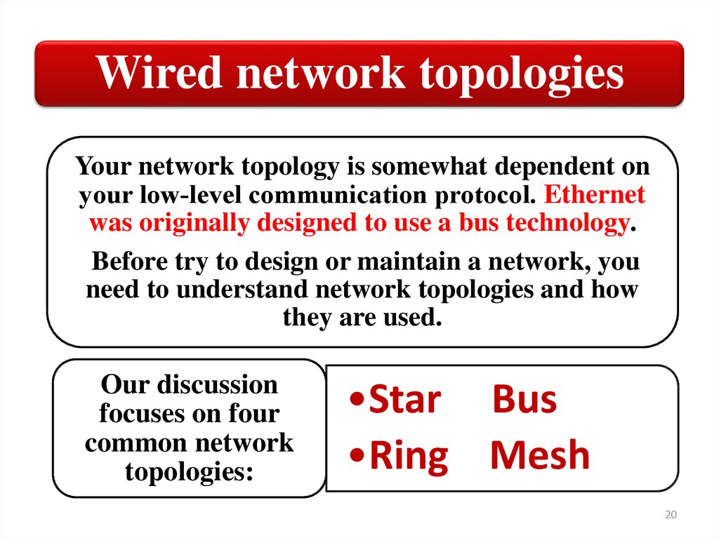
Wired network topologiesYour network topology is somewhat dependent on
your low‐level communication protocol. Ethernet
was originally designed to use a bus technology.
Before try to design or maintain a network, you
need to understand network topologies and how
they are used.
Our discussion
focuses on four
common network
topologies:
•Star Bus
•Ring Mesh
20
21.
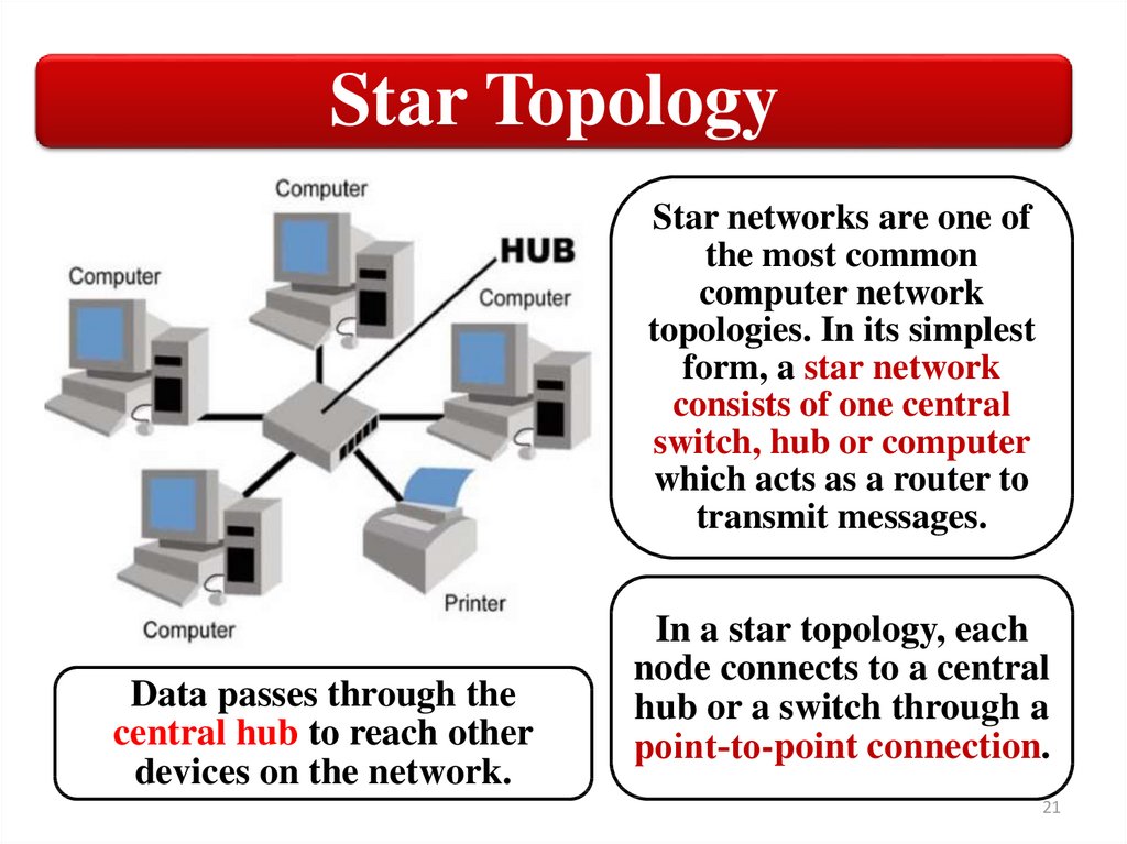
Star TopologyStar networks are one of
the most common
computer network
topologies. In its simplest
form, a star network
consists of one central
switch, hub or computer
which acts as a router to
transmit messages.
Data passes through the
central hub to reach other
devices on the network.
In a star topology, each
node connects to a central
hub or a switch through a
point‐to-point connection.
21
22.
True Star TopologyOnly network that use switch have a true star topology.
If the network uses a hub, the network topology has the physical
appearance of a star, but is actually a bus. That is because when a hub is
used, each computer on the network sees all the packets sent over the
network, just like in a bus topology.
In a true star topology, as when a switch is used, each computer sees
only those packets that were sent specifically to it.
22
23.
Advantages of Star Topology:It is very easy to install and manage star network topology as
it is the simplest of the lot when it comes to functionality.
It is easy to troubleshoot. All computers are dependent on
the central hub which invariably means that any problem
can be traced to the central hub.
As the nodes are not connected to each other, any problem in
one node doesn't hamper the performance of other nodes in
the network.
Adding new machines or replacing the old ones is a lot easy
in this network topology, as disruption of the entire network
is not required to facilitate the same.
23
24.
Disadvantages of Star Topology:The foremost problem with star network topology is the fact
that it is highly dependent on the functioning of central hub.
The size of the network is dependent on how many
connections can be made to the hub.
The performance of the entire network is directly dependent
on the performance of the hub. If the server is slow, it will
cause the entire network to slow down.
If one of the numerous nodes utilizes a significant portion of
the central hub's processing capability, it will reflect on the
performance of other nodes.
24
25.
Bus TopologyEthernet was developed around a logical bus topology. All
network nodes connect directly to the network cable. In theory,
every node has equal, shared access to the cable segment.
Because of the shared access, a bottleneck can develop and slow
transmission when two nodes try to transmit at the same time.
25
26.
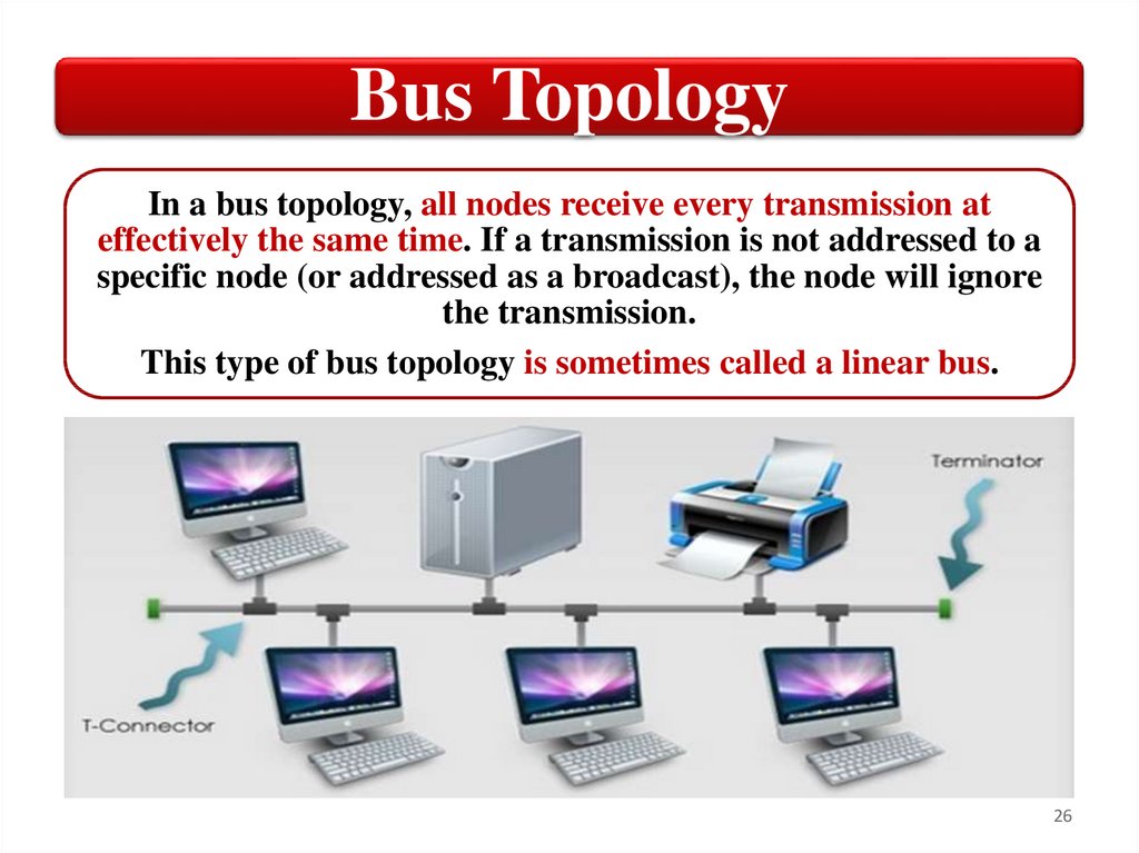
Bus TopologyIn a bus topology, all nodes receive every transmission at
effectively the same time. If a transmission is not addressed to a
specific node (or addressed as a broadcast), the node will ignore
the transmission.
This type of bus topology is sometimes called a linear bus.
26
27.
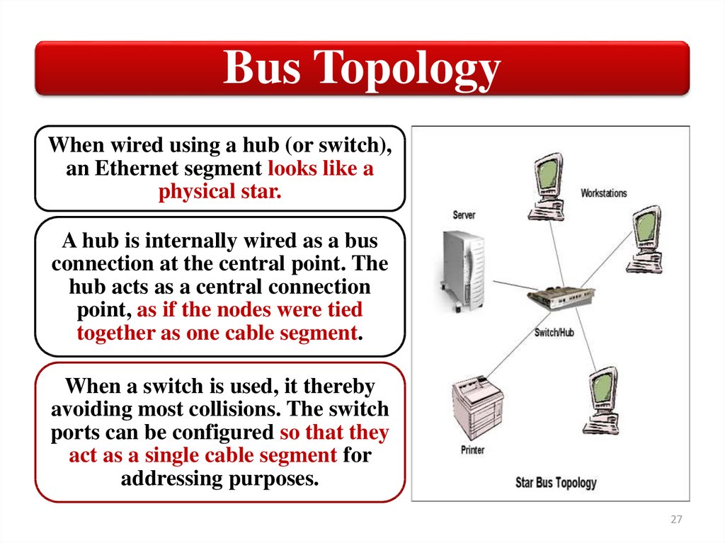
Bus TopologyWhen wired using a hub (or switch),
an Ethernet segment looks like a
physical star.
A hub is internally wired as a bus
connection at the central point. The
hub acts as a central connection
point, as if the nodes were tied
together as one cable segment.
When a switch is used, it thereby
avoiding most collisions. The switch
ports can be configured so that they
act as a single cable segment for
addressing purposes.
27
28.
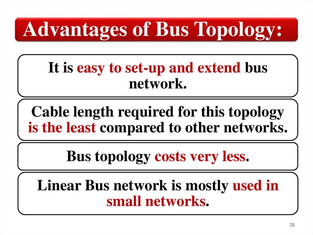
Advantages of Bus Topology:It is easy to set-up and extend bus
network.
Cable length required for this topology
is the least compared to other networks.
Bus topology costs very less.
Linear Bus network is mostly used in
small networks.
28
29.
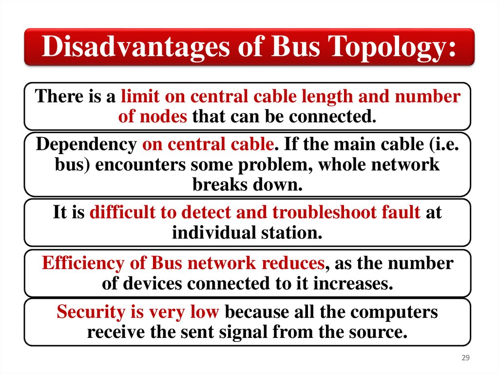
Disadvantages of Bus Topology:There is a limit on central cable length and number
of nodes that can be connected.
Dependency on central cable. If the main cable (i.e.
bus) encounters some problem, whole network
breaks down.
It is difficult to detect and troubleshoot fault at
individual station.
Efficiency of Bus network reduces, as the number
of devices connected to it increases.
Security is very low because all the computers
receive the sent signal from the source.
29
30.
Ring TopologyIn a ring topology, the output of one node is the input of the next node
in a true daisy‐chain configuration. Each node acts as a repeater,
boosting the signal when transmitting to the next node.
A data packet, known as
a token, is passed from
node to node around the
network. A node can
load the token with data,
which is passed around
until it reaches its
destination. At that
point, the data is
unloaded from the token
and the empty token is
passed to the next node.
30
31.
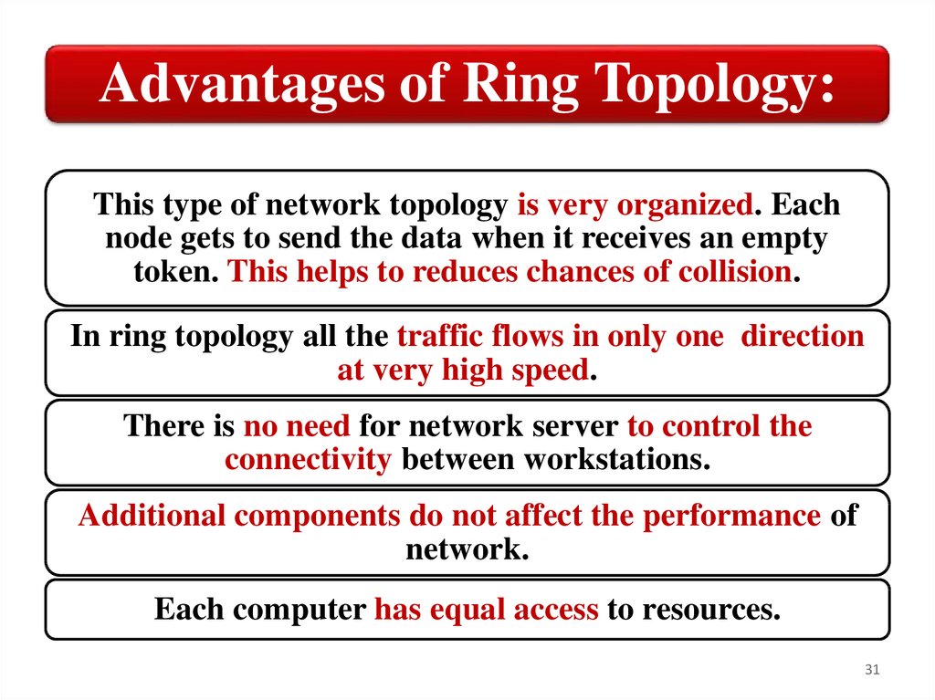
Advantages of Ring Topology:This type of network topology is very organized. Each
node gets to send the data when it receives an empty
token. This helps to reduces chances of collision.
In ring topology all the traffic flows in only one direction
at very high speed.
There is no need for network server to control the
connectivity between workstations.
Additional components do not affect the performance of
network.
Each computer has equal access to resources.
31
32.
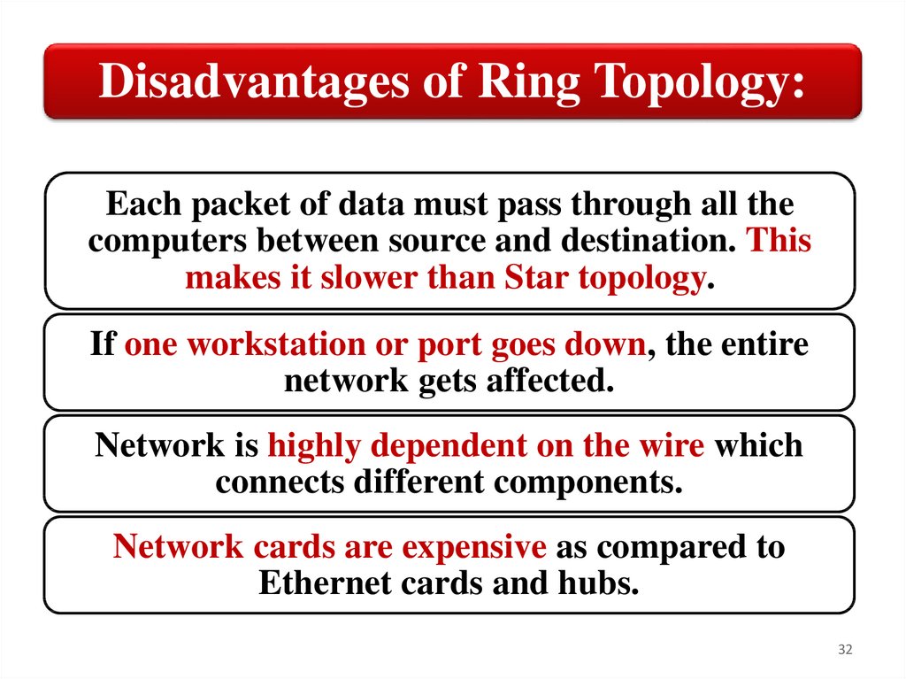
Disadvantages of Ring Topology:Each packet of data must pass through all the
computers between source and destination. This
makes it slower than Star topology.
If one workstation or port goes down, the entire
network gets affected.
Network is highly dependent on the wire which
connects different components.
Network cards are expensive as compared to
Ethernet cards and hubs.
32
33.
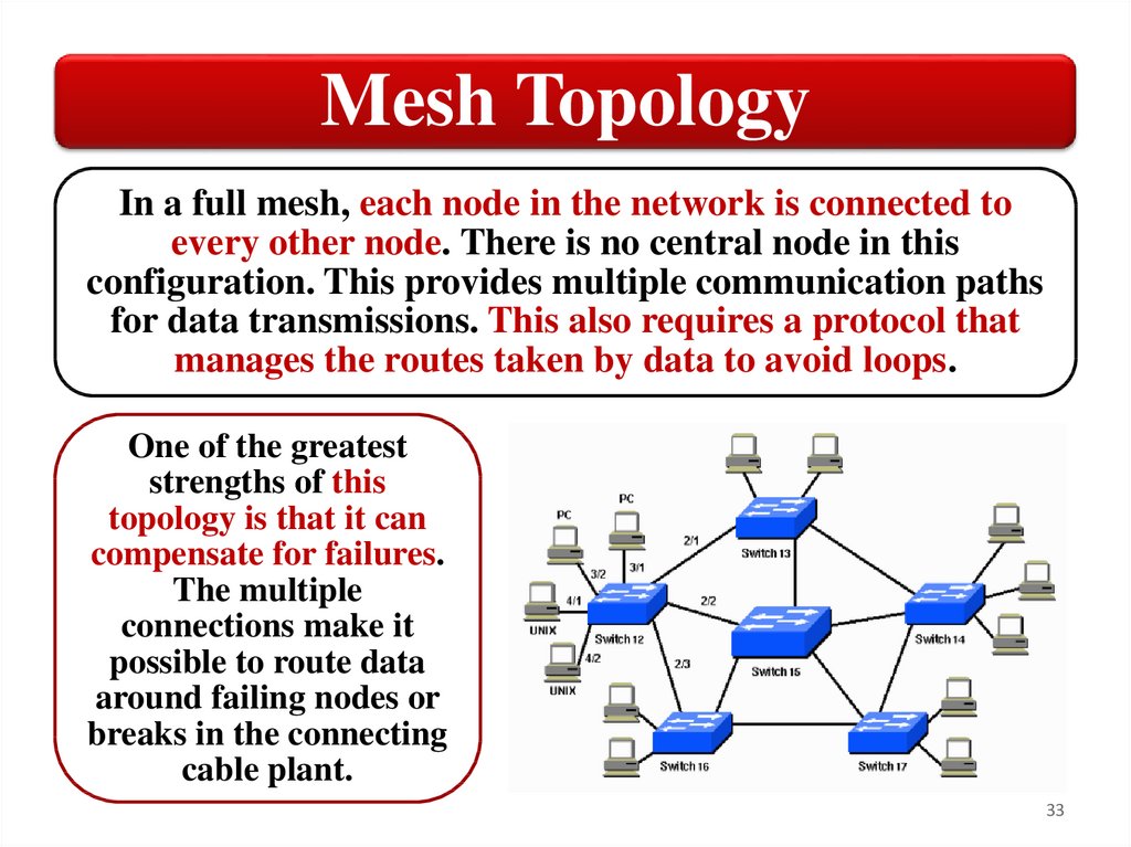
Mesh TopologyIn a full mesh, each node in the network is connected to
every other node. There is no central node in this
configuration. This provides multiple communication paths
for data transmissions. This also requires a protocol that
manages the routes taken by data to avoid loops.
One of the greatest
strengths of this
topology is that it can
compensate for failures.
The multiple
connections make it
possible to route data
around failing nodes or
breaks in the connecting
cable plant.
33
34.
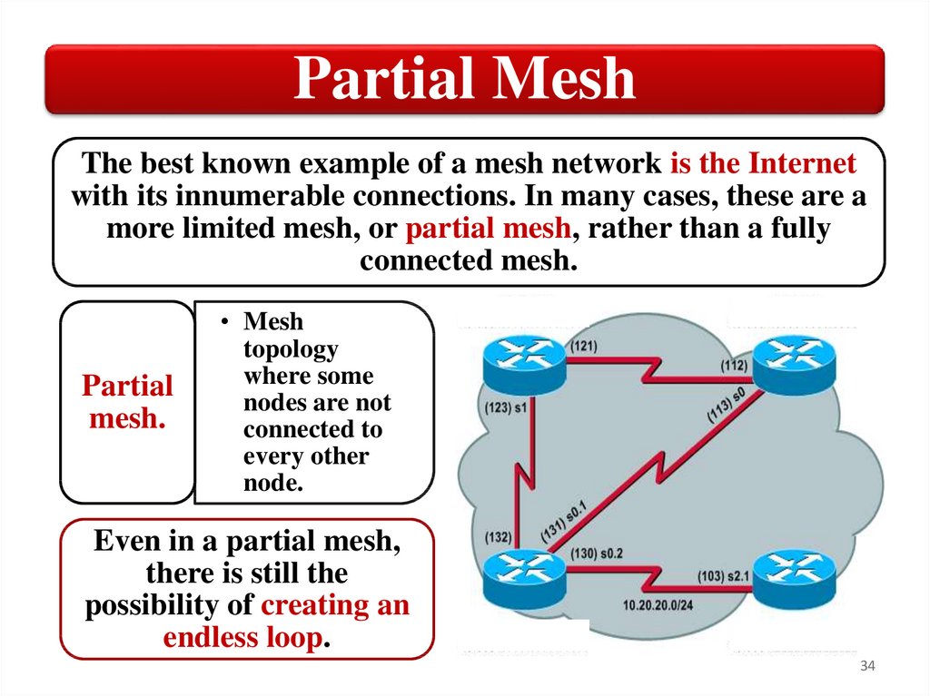
Partial MeshThe best known example of a mesh network is the Internet
with its innumerable connections. In many cases, these are a
more limited mesh, or partial mesh, rather than a fully
connected mesh.
Partial
mesh.
• Mesh
topology
where some
nodes are not
connected to
every other
node.
Even in a partial mesh,
there is still the
possibility of creating an
endless loop.
34
35.
Advantages of Mesh Topology:Data can be transmitted from different devices
simultaneously. This topology can withstand
high traffic.
Even if one of the components fails there is
always an alternative present. So data transfer
doesn’t get affected.
Expansion and modification in topology can
be done without disrupting other nodes.
35
36.
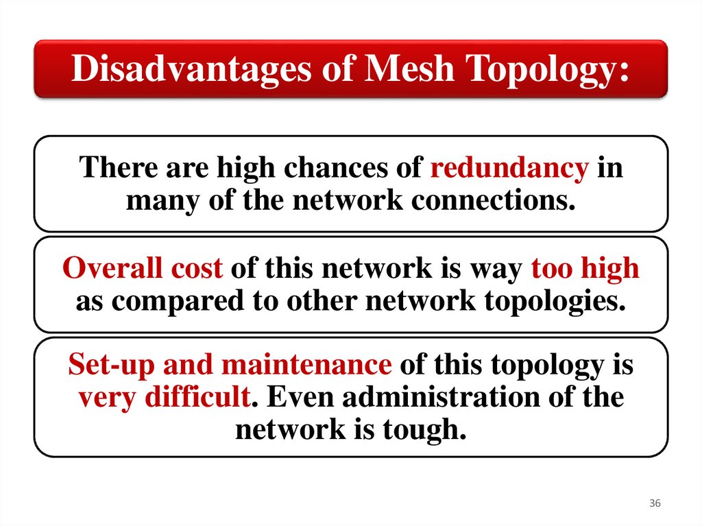
Disadvantages of Mesh Topology:There are high chances of redundancy in
many of the network connections.
Overall cost of this network is way too high
as compared to other network topologies.
Set-up and maintenance of this topology is
very difficult. Even administration of the
network is tough.
36
37.
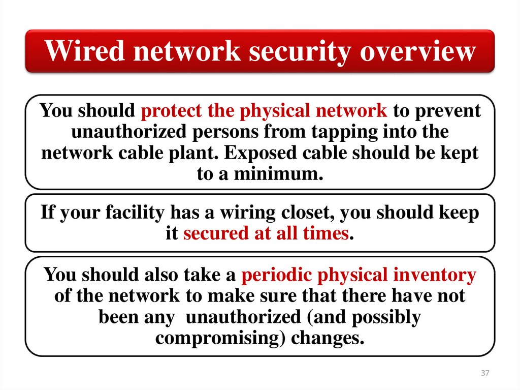
Wired network security overviewYou should protect the physical network to prevent
unauthorized persons from tapping into the
network cable plant. Exposed cable should be kept
to a minimum.
If your facility has a wiring closet, you should keep
it secured at all times.
You should also take a periodic physical inventory
of the network to make sure that there have not
been any unauthorized (and possibly
compromising) changes.
37
38.
SummaryWired network topologies
Star Topology
Bus Topology
Ring Topology
Mesh Topology
Wired network security overview
38
39.
NetworkInfrastructure
3. Compare and contrast common
wireless network configurations
39
40.
Wi-Fi HotspotsWireless computer networks have
now become commonplace. They are
popular in many office
environments, especially because of
their flexibility and relative ease of
management. You even find public
Wi‐Fi networks in places where
people congregate, such as libraries,
colleges, and restaurants.
Some cities are even deploying city‐wide Wi‐Fi to provide
all citizens with free Internet access. New Wi‐Fi
technologies and updated network devices are rolled out on
a regular basis, continually expanding the capabilities of
wireless networks.
40
41.
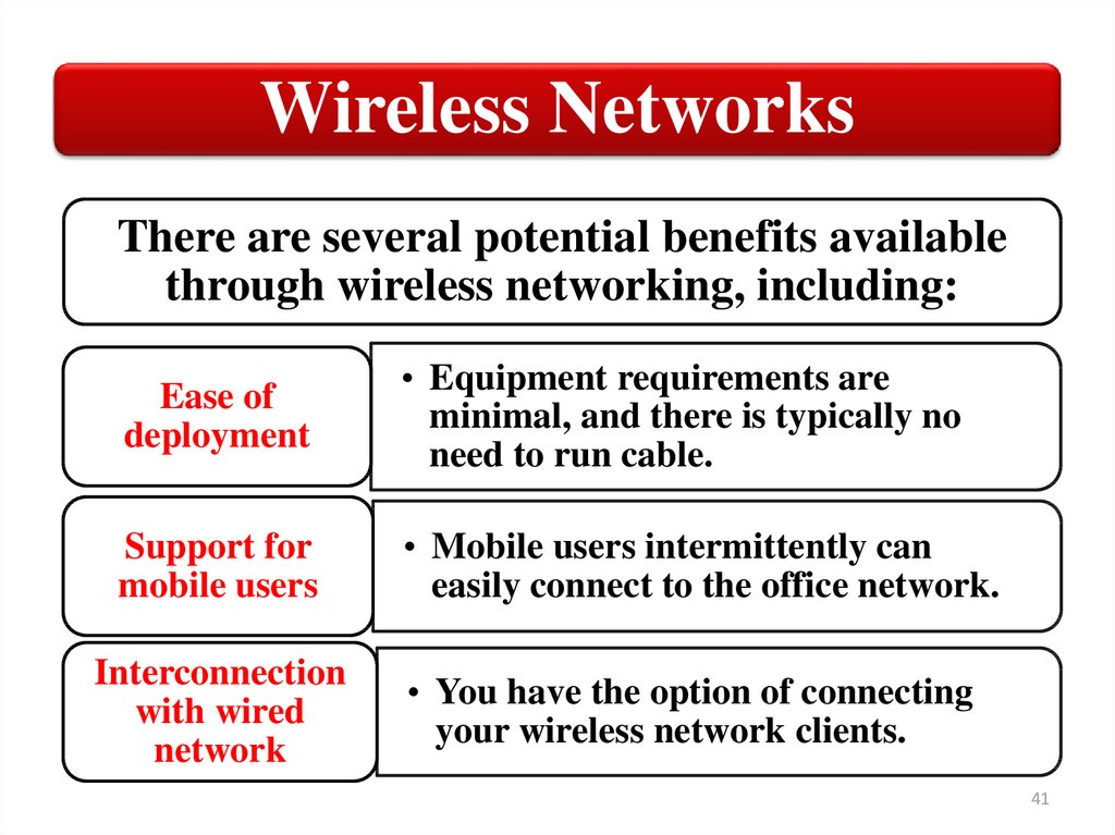
Wireless NetworksThere are several potential benefits available
through wireless networking, including:
Ease of
deployment
• Equipment requirements are
minimal, and there is typically no
need to run cable.
Support for
mobile users
• Mobile users intermittently can
easily connect to the office network.
Interconnection
with wired
network
• You have the option of connecting
your wireless network clients.
41
42.
Wireless network configurationsThere are two basic configuration
options supported for wireless networks:
• Ad‐hoc mode
• Infrastructure mode
The mode you select will depend on your networking
requirements. The operational mode is configured
through the wireless adapter properties.
42
43.
Ad Hoc ModeIn ad‐hoc mode, you configure
wireless devices to
communicate directly with
each other. This enables the
devices to share files and other
resources with each other, but
not with any wired network
devices.
An ad‐hoc network is limited
to no more than nine client
devices. Two devices must be
within range of each other to
share resources. There is no
organized method for
bridging or relaying data
between devices.
43
44.
Ad Hoc ModeTo set up an ad-hoc wireless network, each wireless adapter
must be configured for ad-hoc mode versus the alternative
infrastructure mode.
In addition, all wireless adapters on the ad-hoc network
must use the same SSID (Service Set Identifier) and the
same channel number.
Ad-hoc networks cannot bridge to wired LANs or to the
Internet without installing a special-purpose gateway.
Ad hoc networks make sense when needing to build a
small, all-wireless LAN quickly and spend the minimum
amount of money on equipment.
44
45.
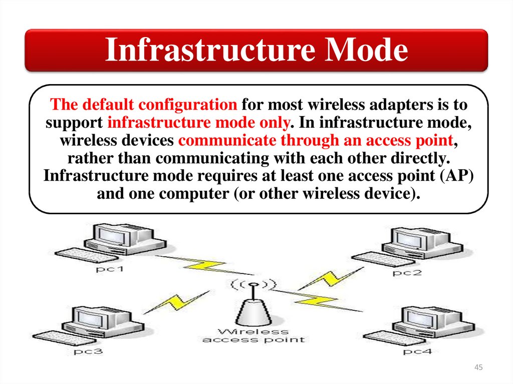
Infrastructure ModeThe default configuration for most wireless adapters is to
support infrastructure mode only. In infrastructure mode,
wireless devices communicate through an access point,
rather than communicating with each other directly.
Infrastructure mode requires at least one access point (AP)
and one computer (or other wireless device).
45
46.
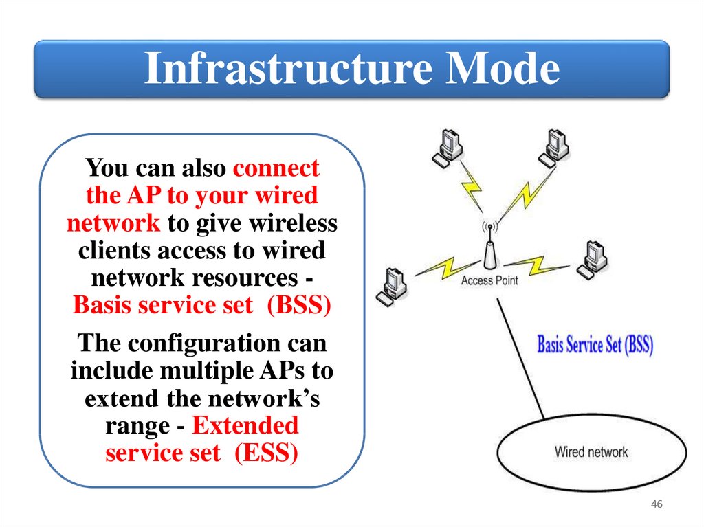
Infrastructure ModeYou can also connect
the AP to your wired
network to give wireless
clients access to wired
network resources Basis service set (BSS)
The configuration can
include multiple APs to
extend the network’s
range - Extended
service set (ESS)
46
47.
Extended service set (ESS)47
48.
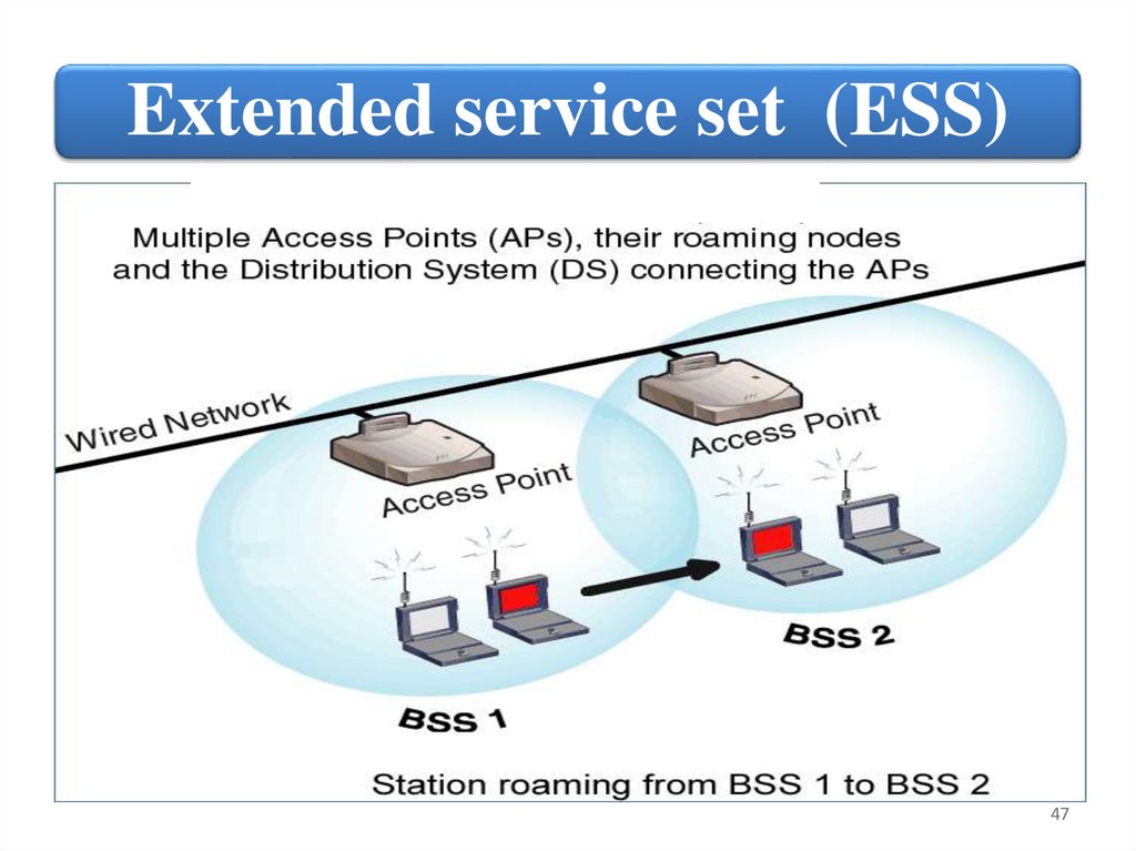
Extended service set definitionAn extended service set (ESS) is a set of
one or more interconnected BSSs and
integrated local area networks (LANs)
that appear as a single BSS to the logical
link control layer at any station associated
with one of those BSSs.
The set of interconnected BSSs must have
a common network name or SSID. They
can work on the same channel, or work on
different channels to boost aggregate
throughput.
48
49.
SSID useEach BSS or ESS is identified by a Service set identifier
(SSID) - a series of 0 to 32 octets. It is used as an identifier
for a wireless LAN, and is intended to be unique for a
particular area.
Since this identifier must often be entered into devices
manually by a human user, it is often a human-readable
string and thus commonly called the "network name".
Wireless devices recognize and select an AP through its
SSID. If the AP broadcasts its SSID, it will appear in the list
of available wireless networks when you attempt to
establish a wireless connection for a device.
Most APs are configured by default to broadcast the SSID.
49
50.
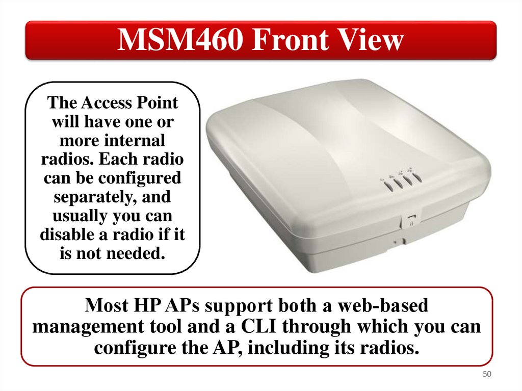
MSM460 Front ViewThe Access Point
will have one or
more internal
radios. Each radio
can be configured
separately, and
usually you can
disable a radio if it
is not needed.
Most HP APs support both a web‐based
management tool and a CLI through which you can
configure the AP, including its radios.
50
51.
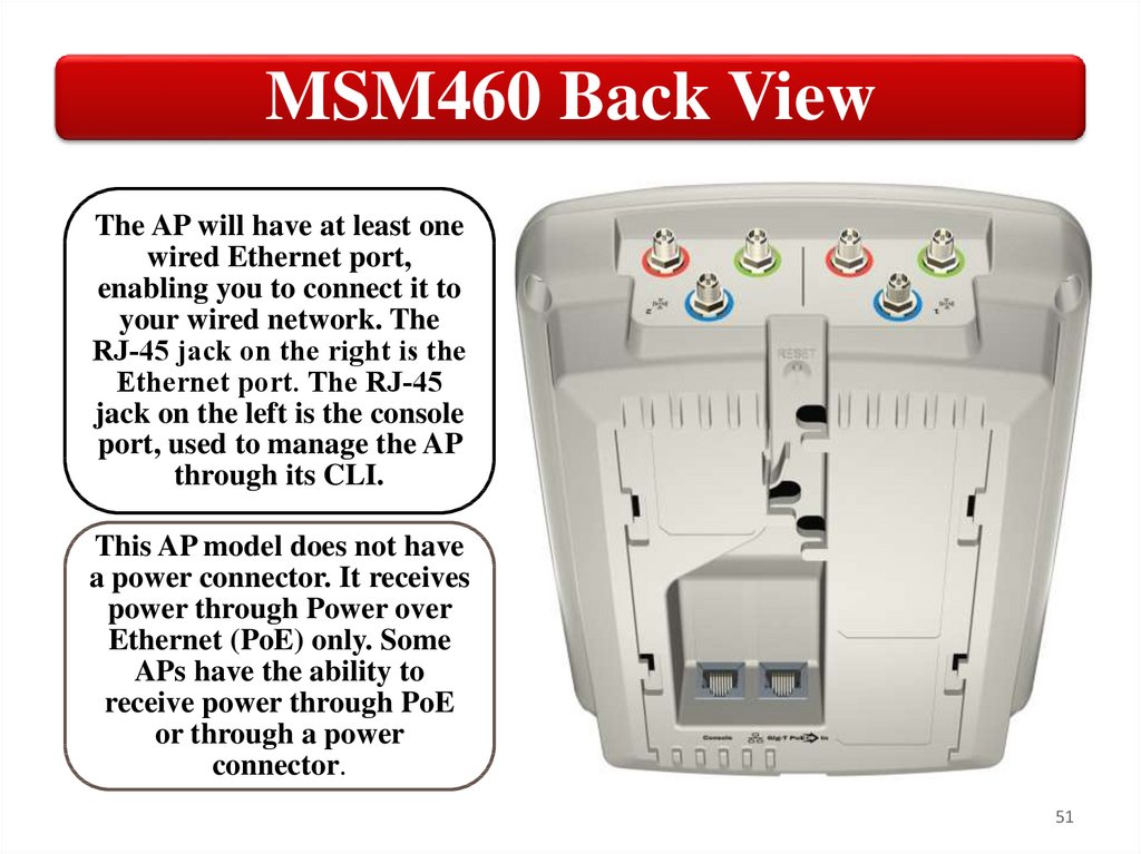
MSM460 Back ViewThe AP will have at least one
wired Ethernet port,
enabling you to connect it to
your wired network. The
RJ‐45 jack on the right is the
Ethernet port. The RJ‐45
jack on the left is the console
port, used to manage the AP
through its CLI.
This AP model does not have
a power connector. It receives
power through Power over
Ethernet (PoE) only. Some
APs have the ability to
receive power through PoE
or through a power
connector.
51
52.
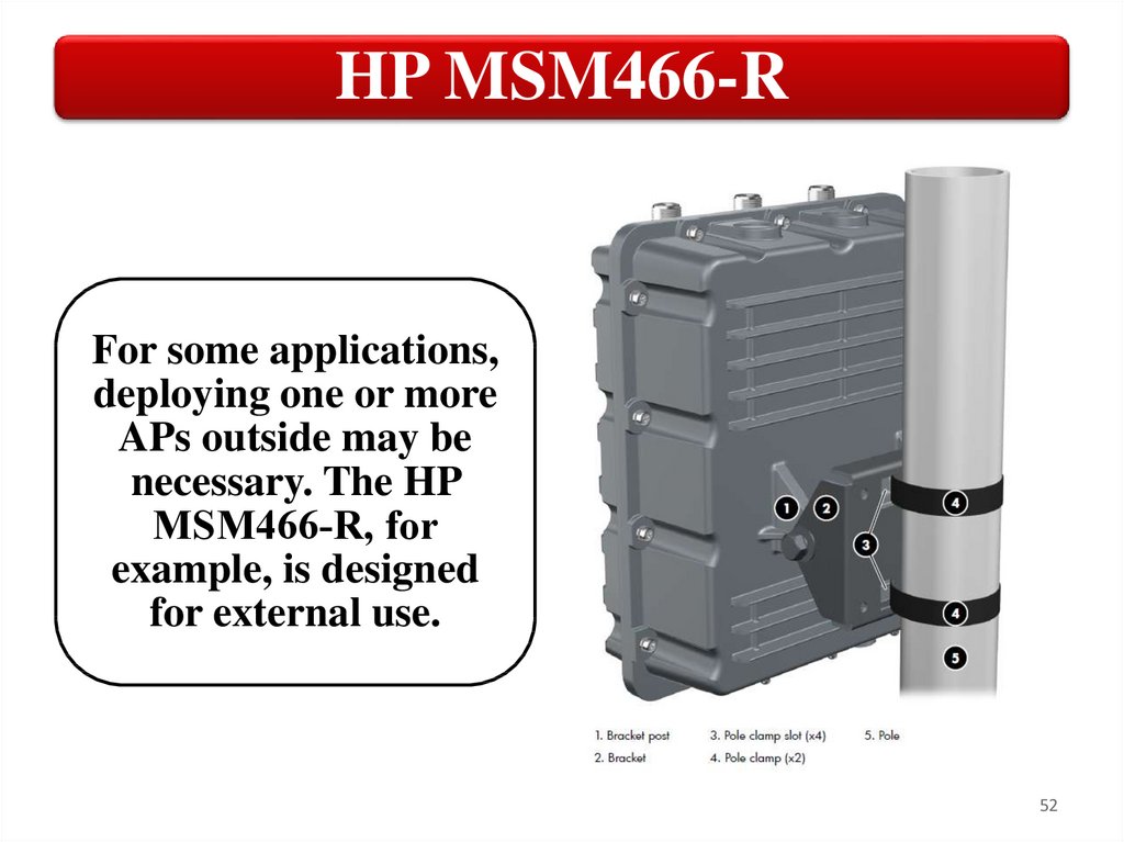
HP MSM466-RFor some applications,
deploying one or more
APs outside may be
necessary. The HP
MSM466‐R, for
example, is designed
for external use.
52
53.
Using APOne important
consideration
is the
placement of
your AP. You
want to place
the AP to avoid
sources of
interference,
including other
APs.
• When using only one AP,
you will typically place it in
as central a location as
possible.
• When using multiple APs,
you should place them in
positions that ensure that
all clients are covered, but
minimize the overlap
between the APs.
53
54.
Using APYou must consider two basic issues when determining how
many Aps you need. One is broadcast range. The other is
the number of simultaneous nodes that the AP can support.
You can configure an AP to limit the maximum number of
nodes. Limiting the number of nodes effectively increases
the potential bandwidth of each node.
A potential concern is the presence of rogue APs. The goal
of a rogue AP is typically to gain access to your network or
collect data from your network. A rogue AP can often be
configured to bypass any security controls you have
implemented. Many APs have the ability to detect and
report rogue APs.
54
55.
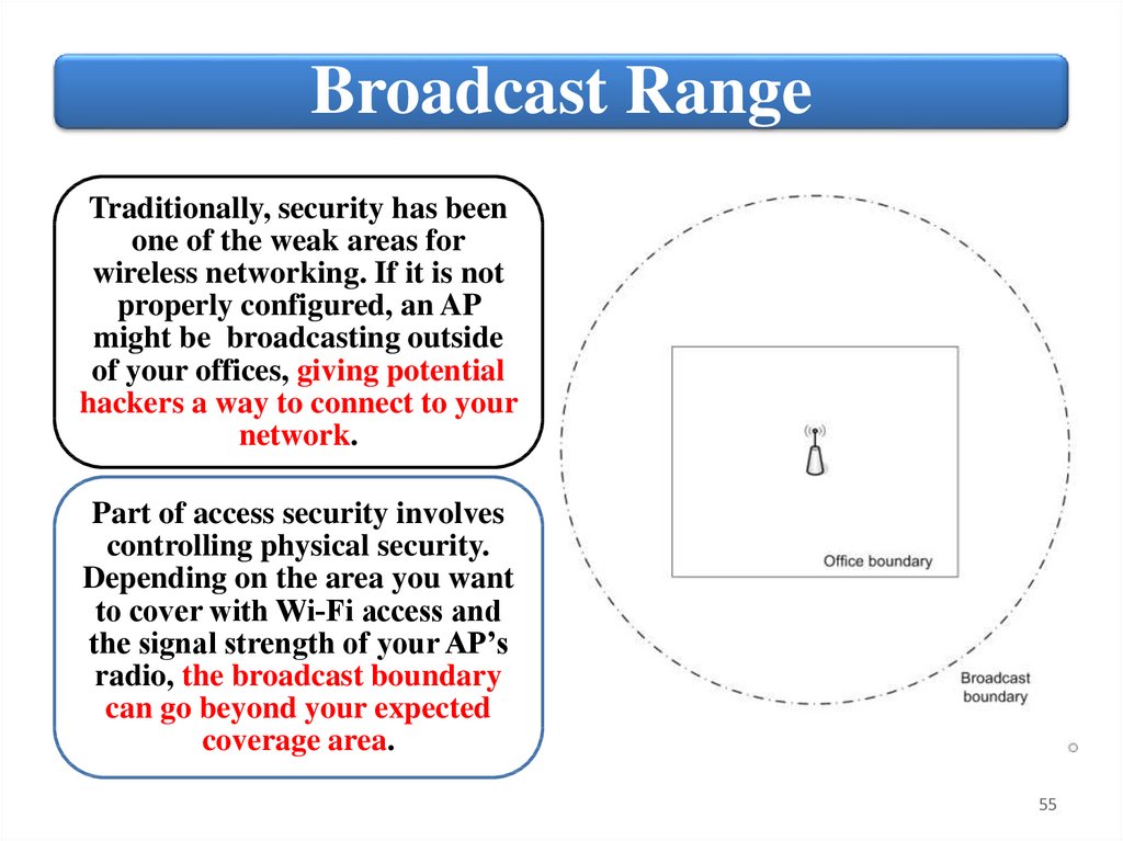
Broadcast RangeTraditionally, security has been
one of the weak areas for
wireless networking. If it is not
properly configured, an AP
might be broadcasting outside
of your offices, giving potential
hackers a way to connect to your
network.
Part of access security involves
controlling physical security.
Depending on the area you want
to cover with Wi‐Fi access and
the signal strength of your AP’s
radio, the broadcast boundary
can go beyond your expected
coverage area.
55
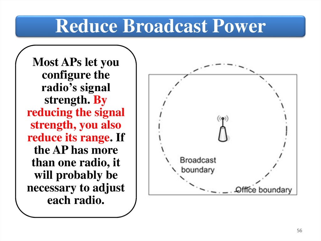
56.
Reduce Broadcast PowerMost APs let you
configure the
radio’s signal
strength. By
reducing the signal
strength, you also
reduce its range. If
the AP has more
than one radio, it
will probably be
necessary to adjust
each radio.
56
57.
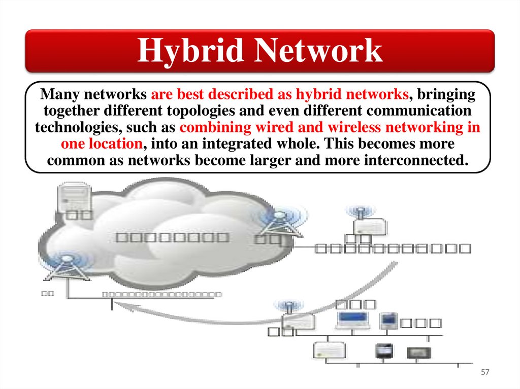
Hybrid NetworkMany networks are best described as hybrid networks, bringing
together different topologies and even different communication
technologies, such as combining wired and wireless networking in
one location, into an integrated whole. This becomes more
common as networks become larger and more interconnected.
57
58.
SummaryWireless network justifications
Wireless network configurations
Ad-hoc and infrastructure modes
The use of hybrid networks
58
59.
NetworkInfrastructure
4. Determine Wireless Distribution
Service (WDS)
59
60.
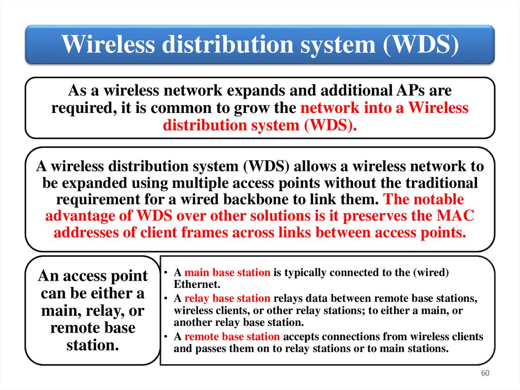
Wireless distribution system (WDS)As a wireless network expands and additional APs are
required, it is common to grow the network into a Wireless
distribution system (WDS).
A wireless distribution system (WDS) allows a wireless network to
be expanded using multiple access points without the traditional
requirement for a wired backbone to link them. The notable
advantage of WDS over other solutions is it preserves the MAC
addresses of client frames across links between access points.
An access point
can be either a
main, relay, or
remote base
station.
• A main base station is typically connected to the (wired)
Ethernet.
• A relay base station relays data between remote base stations,
wireless clients, or other relay stations; to either a main, or
another relay base station.
• A remote base station accepts connections from wireless clients
and passes them on to relay stations or to main stations.
60
61.
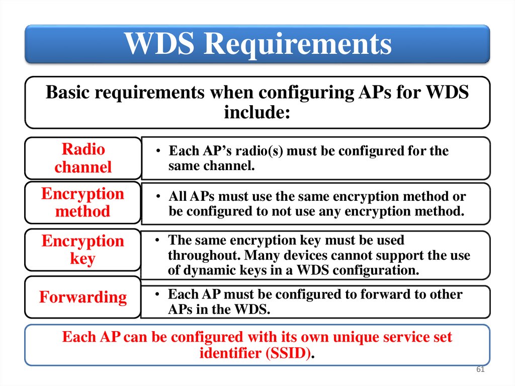
WDS RequirementsBasic requirements when configuring APs for WDS
include:
Radio
channel
• Each AP’s radio(s) must be configured for the
same channel.
Encryption
method
• All APs must use the same encryption method or
be configured to not use any encryption method.
Encryption
key
• The same encryption key must be used
throughout. Many devices cannot support the use
of dynamic keys in a WDS configuration.
Forwarding
• Each AP must be configured to forward to other
APs in the WDS.
Each AP can be configured with its own unique service set
identifier (SSID).
61
62.
WDS ExamplesWhen setting up WDS, you can
configure an AP to operate in a
wireless bridging mode or wireless
repeating mode. In some
configurations, you will be using
different APs set up to do each. The
easiest way to understand these
different configurations is to look at
the following few examples.
62
63.
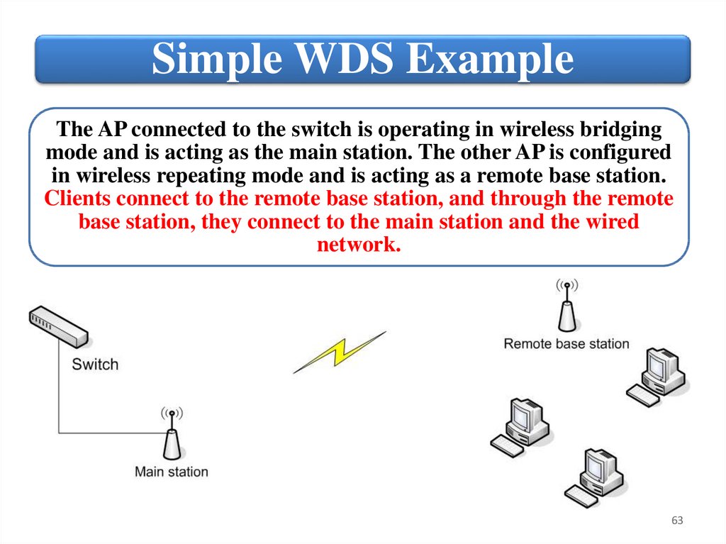
Simple WDS ExampleThe AP connected to the switch is operating in wireless bridging
mode and is acting as the main station. The other AP is configured
in wireless repeating mode and is acting as a remote base station.
Clients connect to the remote base station, and through the remote
base station, they connect to the main station and the wired
network.
63
64.
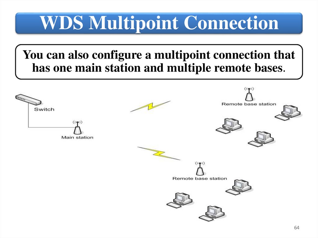
WDS Multipoint ConnectionYou can also configure a multipoint connection that
has one main station and multiple remote bases.
64
65.
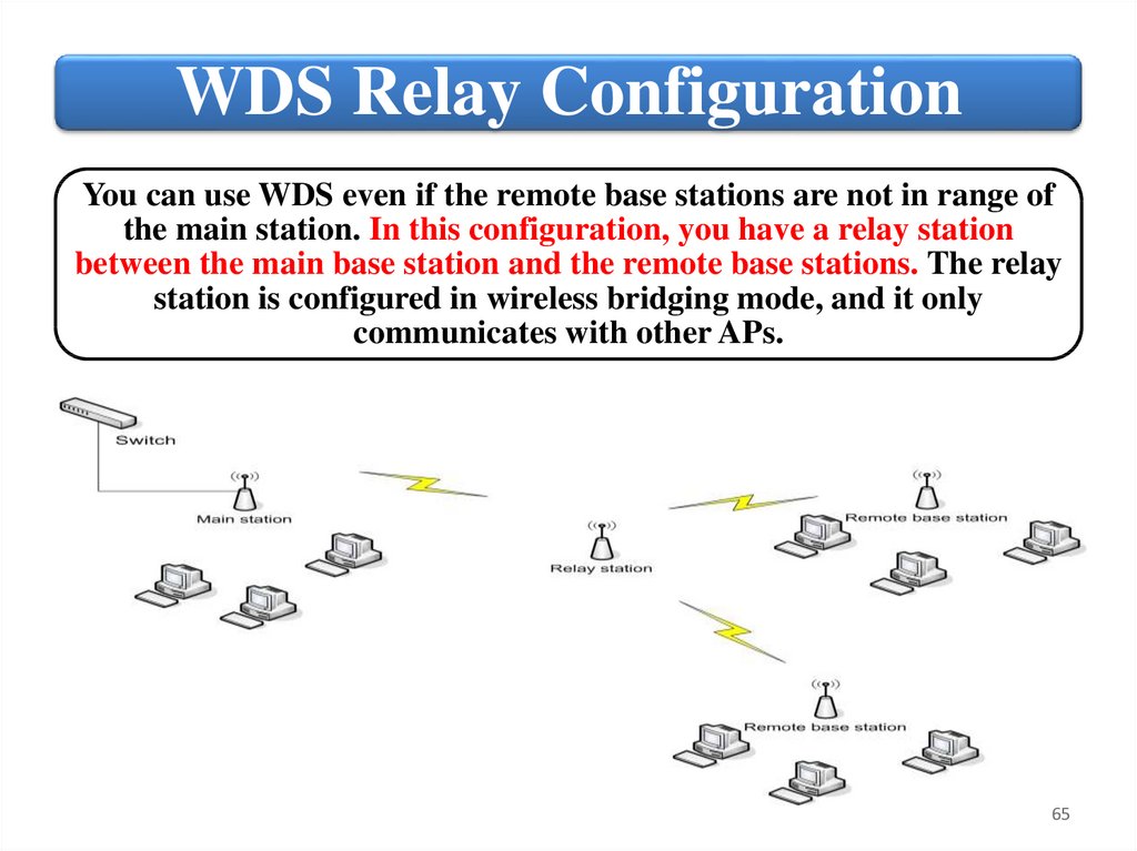
WDS Relay ConfigurationYou can use WDS even if the remote base stations are not in range of
the main station. In this configuration, you have a relay station
between the main base station and the remote base stations. The relay
station is configured in wireless bridging mode, and it only
communicates with other APs.
65
66.
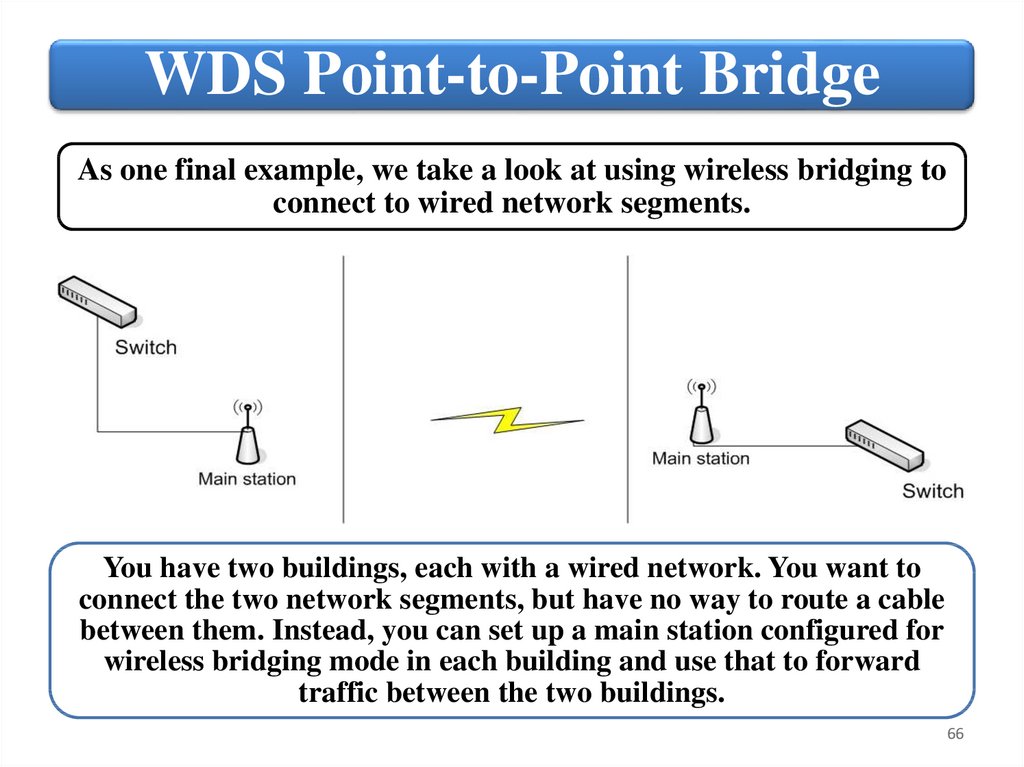
WDS Point-to-Point BridgeAs one final example, we take a look at using wireless bridging to
connect to wired network segments.
You have two buildings, each with a wired network. You want to
connect the two network segments, but have no way to route a cable
between them. Instead, you can set up a main station configured for
wireless bridging mode in each building and use that to forward
traffic between the two buildings.
66
67.
MSM760 ControllerWhen deploying an HP AP, you will need to configure the management
mode. The following two modes are supported:
Controlled Mode
Autonomous Mode
• The AP is controlled and managed through an HP
MSM7xx Controller. All configuration settings are
provided by the controller.
• The AP acts as a stand‐alone AP and must beconfigured
manually.
67
68.
MSM760 ControllerWhen configured for controlled mode, the AP will attempt to locate
a controller by default when it powers up. It will take all of its
configuration settings from the controller. If the AP is unable to
locate and connect with a controller, it will not be operational.
The advantage of controlled mode is that it lets you centrally
manage all of your APs. When you have to support multiple APs,
central management is more efficient and secure, and it also
ensures consistent configurations.
When you set up a WDS, the controller acts as your main station.
The controller connects to the wired network. It also has the
firewall and security capabilities to let you configure both an
internal network and a public Wi‐Fi hot spot through the same
controller. It can act as a NAT device to enable Internet access to
both employees and guests accessing your public Wi‐Fi.
68
69.
NetworkInfrastructure
5. Compare wireless network security
options
69
70.
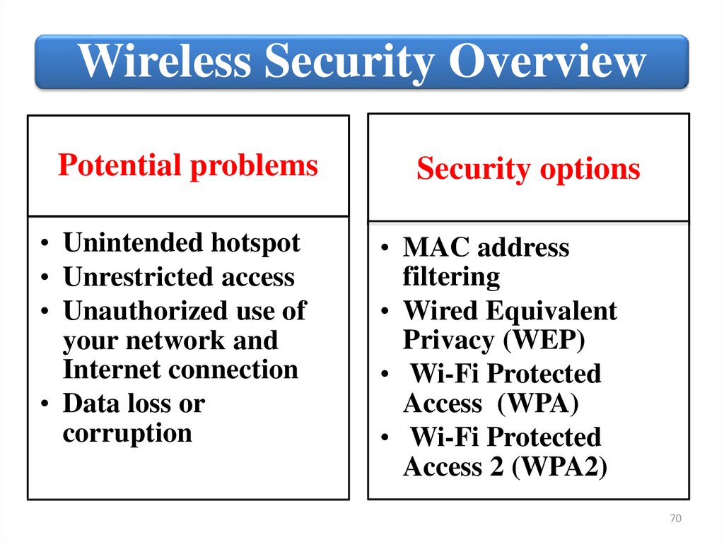
Wireless Security OverviewPotential problems
• Unintended hotspot
• Unrestricted access
• Unauthorized use of
your network and
Internet connection
• Data loss or
corruption
Security options
• MAC address
filtering
• Wired Equivalent
Privacy (WEP)
• Wi-Fi Protected
Access (WPA)
• Wi-Fi Protected
Access 2 (WPA2)
70
71.
Wireless Security MAC address filteringMAC address filters are often used as an added
wireless security measure next to data encryption.
A MAC address (or hardware address or physical
address) is a unique code that is assigned to almost
all-networking hardware such as Ethernet cards,
routers, mobile phones, wireless cards and so on.
You can use the MAC address to either allow or
block a wireless network card that tries to connect
to the wireless network.
71
72.
Wireless Security - WEPWired Equivalent Privacy (WEP) is a security
algorithm for IEEE 802.11 wireless networks.
Two methods of
• Open System authentication
authentication can
be used with WEP: • Shared Key authentication.
In Open System authentication, the WLAN client
need not provide its credentials to the Access Point
during authentication. Any client can authenticate
with the Access Point and then attempt to
associate. In effect, no authentication occurs.
72
73.
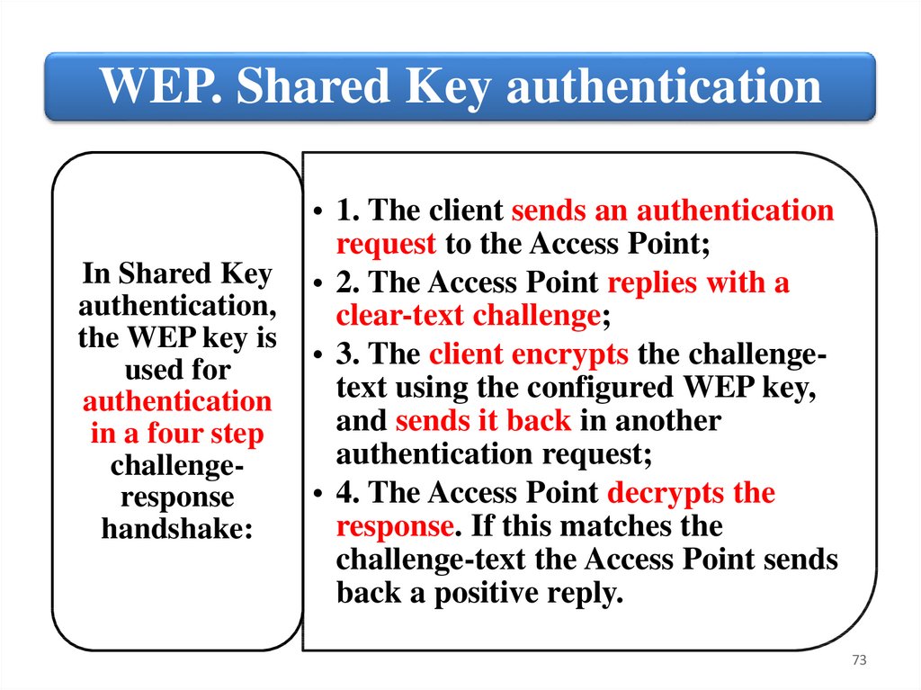
WEP. Shared Key authenticationIn Shared Key
authentication,
the WEP key is
used for
authentication
in a four step
challengeresponse
handshake:
• 1. The client sends an authentication
request to the Access Point;
• 2. The Access Point replies with a
clear-text challenge;
• 3. The client encrypts the challengetext using the configured WEP key,
and sends it back in another
authentication request;
• 4. The Access Point decrypts the
response. If this matches the
challenge-text the Access Point sends
back a positive reply.
73
74.
Wireless Security - WPAWi-Fi Protected Access (WPA) is a security protocols
and security certification programs developed to
secure wireless computer networks. WPA improves
on the authentication and encryption features of WEP
(Wired Equivalent Privacy).
WPA provides
stronger encryption
than WEP through
use of either of two
standard
technologies:
• Temporal Key Integrity
Protocol (TKIP) – WPA;
• Advanced Encryption
Standard (AES) –
WPA2.
74
75.
Temporal Key Integrity Protocol (TKIP)TKIP uses the RC4 stream encryption algorithm as its basis.
The new protocol, however, encrypts each data packet with a
unique encryption key, and the keys are much stronger than
those of its predecessor. To increase key strength, TKIP
includes four additional algorithms:
• A cryptographic message integrity check to protect packets.
• An initialization-vector sequencing mechanism that includes
hashing, as opposed to WEP's plain text transmission.
• A per-packet key-mixing function to increase cryptographic
strength.
• A re-keying mechanism to provide key generation every
10,000 packets.
75
76.
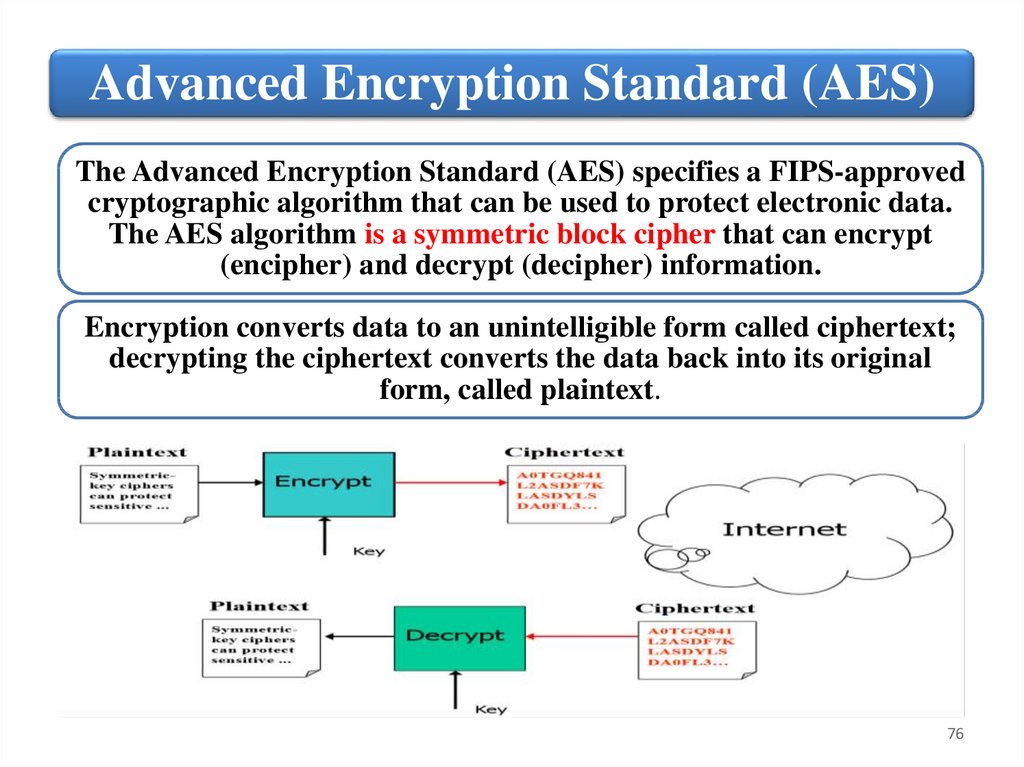
Advanced Encryption Standard (AES)The Advanced Encryption Standard (AES) specifies a FIPS-approved
cryptographic algorithm that can be used to protect electronic data.
The AES algorithm is a symmetric block cipher that can encrypt
(encipher) and decrypt (decipher) information.
Encryption converts data to an unintelligible form called ciphertext;
decrypting the ciphertext converts the data back into its original
form, called plaintext.
76
77.
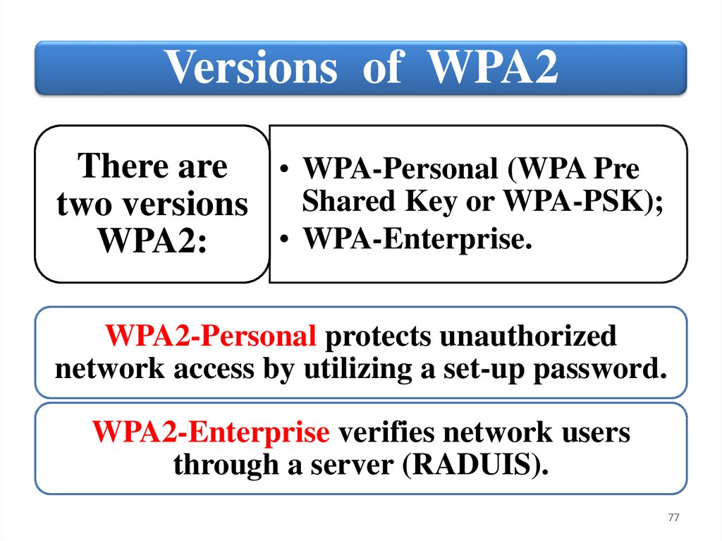
Versions of WPA2There are • WPA-Personal (WPA Pre
two versions Shared Key or WPA-PSK);
• WPA-Enterprise.
WPA2:
WPA2-Personal protects unauthorized
network access by utilizing a set-up password.
WPA2-Enterprise verifies network users
through a server (RADUIS).
77
78.
SummaryPotential problems wireless network security
MAC address filtering
Wired Equivalent Privacy (WEP)
Wi-Fi Protected Access (WPA)
Wi-Fi Protected Access 2 (WPA2)
78
79.
NetworkInfrastructure
6. Describe the purpose and use of
key network technologies
79
80.
Key Network TechnologiesWe end this lecture with a
brief discussion of some
technologies and concepts
that are central to
understanding modern
network infrastructures.
The discussion is designed
to serve only as an
overview of the subject.
These topics will be
covered in much greater
detail at later times
throughout this course:
• Network
Segmentation
• Firewall and
Perimeter Network
• Network Address
Translation (NAT)
• Proxy Server
• Virtual Private
Network (VPN)
80
81.
Network SegmentationNetwork segmentation in computer
networking is the act of splitting a
computer network into subnetworks, each
being a network segment.
There are several
reasons why you
might consider
segmenting a
network,
including:
• Optimizing network
communication
• Improving the management of
network traffic flows
• Enhancing network security
management
81
82.
Network Segmentation exampleIn this example, segmentation accommodates the needs
of two diverse work groups. Both servers have reduced
overhead and traffic because accounting rarely
accesses the engineering side and vice versa. However,
each side can still access the other’s server for e-mail,
budget reports, and other cross-enterprise activities.
82
83.
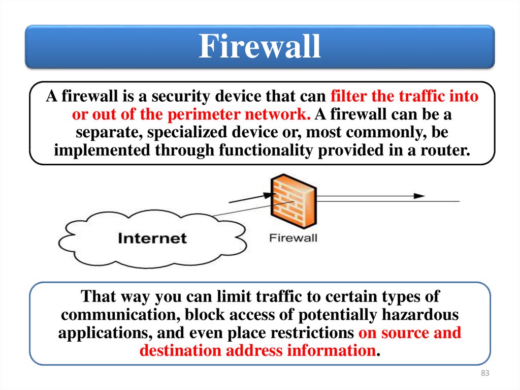
FirewallA firewall is a security device that can filter the traffic into
or out of the perimeter network. A firewall can be a
separate, specialized device or, most commonly, be
implemented through functionality provided in a router.
That way you can limit traffic to certain types of
communication, block access of potentially hazardous
applications, and even place restrictions on source and
destination address information.
83
84.
Perimeter NetworkOne specialized type of segmentation is a perimeter
network (DMZ). A perimeter network is a screened subnet
that sits between the internal LAN and the outside world,
specifically the Internet. The perimeter network acts as a
buffer to protect your network. It is designed to help
prevent unauthorized access into your network, as well as
targeted attacks against it.
The primary purpose of a perimeter network is that it gives
you a place to deploy devices (NAT, Proxy, RADIUS) that you
want to share with the world at large.
84
85.
Address translationAddress translation is another important technology for when
devices on an internal network need to access the outside world.
Therefore, you should always hide the IP addresses of your LAN
computers. You should also often use private IP addresses to
configure internal hosts. When you use private IP addresses, you
must use address translation when accessing the Internet.
Private IP
addresses.
• IP address ranges that can be assigned as internal
LAN addresses, but cannot be used for
communication on the Internet.
You can hide the IP addresses of LAN computers and use private
addresses on your network by using a Network Address
Translation (NAT) server. A NAT server substitutes a valid
Internet address for a host’s actual address.
85
86.
Proxy ServerOne type of specialized server you might find in a perimeter
network is a proxy server, which one manages Internet access .
Clients can access a
proxy server by
going through the
following steps:
• The client makes a request to the proxy server.
• The proxy server queries the Internet resource
and retrieves the result.
• The proxy server passes the result to the
requesting client.
The use of a proxy server helps to improve network security. It
also adds a layer of administrative control, letting you restrict
users’ access to Web sites you do not want them browsing.
Proxy servers also help reduce the amount of traffic between
your network and the Internet. As information is retrieved
from the Internet, it is buffered on the proxy server.
86
87.
Virtual Private Network (VPN)A VPN is designed to provide a secure, reliable communication path
over a less secure communication media. The most common use of a
VPN is to provide secure communication between two remote sites,
using the Internet as your carrier. With a VPN, a communication
session is established between two endpoints. The two most
common scenarios are LAN‐to‐LAN communication and
computer‐to‐LAN communication.
At each end, a device, typically a router, is configured as the VPN endpoint.
Communication is typically encrypted between the two endpoints only.
VPNs rely on the use of tunneling protocols to carry data between the
endpoints. The endpoints must be able to mutually authenticate each other
when a communication session is established to ensure security.
87
88.
SummaryReasons for network segmentation.
Use of perimeter networks.
Justification for proxy and address
translation (NAT) servers.
VPN fundamentals.
88